EP2154048A1 - Vehicle steering column - Google Patents
Vehicle steering column Download PDFInfo
- Publication number
- EP2154048A1 EP2154048A1 EP09167454A EP09167454A EP2154048A1 EP 2154048 A1 EP2154048 A1 EP 2154048A1 EP 09167454 A EP09167454 A EP 09167454A EP 09167454 A EP09167454 A EP 09167454A EP 2154048 A1 EP2154048 A1 EP 2154048A1
- Authority
- EP
- European Patent Office
- Prior art keywords
- tilt lever
- lever shaft
- upper bracket
- link member
- bracket
- Prior art date
- Legal status (The legal status is an assumption and is not a legal conclusion. Google has not performed a legal analysis and makes no representation as to the accuracy of the status listed.)
- Granted
Links
- 230000003993 interaction Effects 0.000 description 3
- 238000010521 absorption reaction Methods 0.000 description 2
- 238000010586 diagram Methods 0.000 description 2
- 230000002146 bilateral effect Effects 0.000 description 1
- 230000008878 coupling Effects 0.000 description 1
- 238000010168 coupling process Methods 0.000 description 1
- 238000005859 coupling reaction Methods 0.000 description 1
- 230000002093 peripheral effect Effects 0.000 description 1
- 238000003466 welding Methods 0.000 description 1
Images
Classifications
-
- B—PERFORMING OPERATIONS; TRANSPORTING
- B62—LAND VEHICLES FOR TRAVELLING OTHERWISE THAN ON RAILS
- B62D—MOTOR VEHICLES; TRAILERS
- B62D1/00—Steering controls, i.e. means for initiating a change of direction of the vehicle
- B62D1/02—Steering controls, i.e. means for initiating a change of direction of the vehicle vehicle-mounted
- B62D1/16—Steering columns
- B62D1/18—Steering columns yieldable or adjustable, e.g. tiltable
- B62D1/184—Mechanisms for locking columns at selected positions
Definitions
- the invention relates to a vehicle steering column provided with a tilt mechanism.
- Vehicle steering columns provided with a tilt mechanism are typically such that, after releasing a locking mechanism that holds the steering column at a tilted position by operating a tilt lever, a column tube inserted with a steering shaft is adjusted to a desired angle position by tilting about a tilting fulcrum shaft, and the locking mechanism is then locked by operating the tilt lever while in that position.
- An example of this type of conventional vehicle steering column is described in Japanese Patent Application Publication No. 2000-344115 ( JP-A-2000-344115 ).
- An object of the invention is to provide a vehicle steering column capable of holding a steering column in position even after a locking mechanism has been released.
- the vehicle steering column in one aspect of the invention includes: a column tube (11) capable of pivoting about a tilting fulcrum shaft (12); an upper bracket (22) that clamps a distance bracket (21) fixed to the column tube (11) so that the distance bracket (21) is movably adjusted with respect to the upper bracket (22) in an up-down direction; a tilt lever shaft (25) that passes through the distance bracket (21); and a tilt lever (31) which is rotatably attached to the tilt lever shaft (25), and the tilt lever (31) locking and releasing the distance bracket (21) to and from the upper bracket (22).
- a plurality of grooves (30a) that removably engage with the tilt lever shaft (25) are provided in the upper bracket (22), a link member (27) is pivotally supported by the column tube (11) or a member integrated with the column tube (11), and the tilt lever shaft (25) is attached to the link member (27) to be removably engaged with the grooves (30a) of the upper bracket (22) by pivoting of the link member (27).
- a plurality of grooves removably engaging with a tilt lever shaft are provided in an upper bracket, a link member is pivotally supported by a column tube or a member integrated with the column tube, and a tilt lever shaft is attached to the link member to be removably engaged with the grooves of the upper bracket by pivoting of the link member.
- the grooves (30a) of the upper bracket (22) may be formed in a serrated shape.
- the tilt lever shaft is able to smoothly engage with the grooves regardless of the position of the steering wheel in the up-down direction.
- an urging member (35) that urges the link member (27) so that the tilt lever shaft (25) engages with the grooves (30a), may also be included.
- the tilt lever shaft can be made to reliably and easily engage with the grooves by the urging force of the urging member.
- a slot (26) in which the tilt lever shaft (25) is disposed may be provided in the distance bracket (21), and a range of pivoting of the link member (27) may be limited by the slot (26).
- a slot in which the tilt lever shaft is disposed is provided in the distance bracket, and a range of pivoting of the link member is limited by the slot, an amount of pivoting of the link member as determined by operation of the tilt lever can be limited within the minimum required range in which the tilt lever shaft disengages from the grooves.
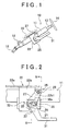
- FIG. 1 shows a schematic diagram of a vehicle steering column 10 in this embodiment.
- a column tube 11 is pivotally supported by a tilting fulcrum shaft 12 and can be adjusted by pivoting about the tilting fulcrum shaft 12.
- a steering shaft 13 is rotatably fit into a shaft center portion of the column tube 11.
- a steering wheel 14 is attached to one end of the steering shaft 13.
- a shaft coupling in the form of an intermediate shaft 15 is coupled to the other end of the steering shaft 13.
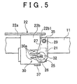
- a distance bracket 21 is fastened to the column tube 11.
- the distance bracket 21 is clamped to an upper bracket 22 fixed to a vehicle body 23 (see FIG. 1 ) while being allowing to move by adjustment in the up-down direction.
- the upper bracket 22 has a pair of members having an L-shaped cross-section, including of a flange portion 22a extending along the column tube 11 and a sidewall portion 22b extending downward vertically from one end of the flange portion 22a, arranged back-to-back in bilateral symmetry, and each flange portion 22a is fixed to the vehicle body 23 with bolts and the like.
- An arcuate portion 21a is formed in a central portion of the distance bracket 21, and the outer peripheral surface of the column tube 11 is contacted by this arcuate portion 21a and is fixed by welding and the like.
- the distance bracket 21 is arranged between both sidewall portions 22b of the upper bracket 22, and is clamped to both sidewall portions 22b while allowed to make sliding contact therewith.
- a slot 26 having a configuration to be described later is formed in the distance bracket 21 and through which is inserted a tilt lever shaft 25 in the horizontal direction at a right angle to the axial line of the steering shaft 13.
- the tilt lever shaft 25 is supported by a link member 27 that is pivotally supported by the column tube 11 while allowing to pivot about an axial line parallel to the tilt lever shaft 25.
- a pair of support brackets 28 are respectively fixed to the circumferential surface of the column tube 11 at a slight distance away from one end 22b1 of the sidewall portion 22b of the upper bracket 22 towards the steering wheel 14, and pivot shafts 29 are respectively provided in these support brackets 28 parallel to the tilt lever bracket 25.
- the link member 27 able to make sliding contact with each outer surface of both sidewall portions 22b of the upper bracket 22 is supported by each pivot shaft 29 while respectively able to pivot about an axial line parallel to the tilt lever shaft 25.
- the tilt lever shaft 25 is inserted through the distal end of the link member 27 parallel to the pivot shafts 29, and the tilt lever shaft 25 protrudes from both sides of each link member 27 after passing through the upper bracket 22 and the distance bracket 21.
- an engaging portion 30, consisting of a plurality of grooves 30a cut out into a serrated shape that open towards the one end 22b1 on the side of the steering wheel 14, is formed in both sidewall portions 22b of the upper bracket 22, and the tilt lever shaft 25 is removably engaged with these grooves 30a by tilting of the link member 27.
- the grooves 30a of the engaging portion 30 formed in both sidewall portions 22b of the upper bracket 22 are formed into a V-shape along an arcuate locus centered about the pivot shafts 29.
- the slot 26 formed in the distance bracket 21 is formed in an arc centering about the pivot shafts 29 or in a straight line approximating this arc.
- the amount of movement of the tilt lever shaft 25, or in other words, the amount of tilting of the link member 27, is restricted by this slot 26, and pivoting of the link member 27 is restricted at the position where the tilt lever shaft 25 has disengaged from the engaging portion 30.
- the tilt lever shaft 25 protrudes from the link member 27 on both sides after passing through the slot 26 formed in the distance bracket 21 and the grooves 30a formed in both sidewall portions 22b of the upper bracket 22.
- a flange-shaped head portion 25a that contacts an end surface of one link member 27 is formed on one of the protruding ends of the tilt lever shaft 25, while a threaded portion 25b is formed on the other protruding end.
- a nut 32 integrally provided on the tilt lever 31 is screwed onto the threaded portion 25b.
- the tilt lever shaft 25 is prevented from turning by engaging with the serrations in the link members 27 on both sides.
- both sidewall portions 22b of the upper bracket 22 are tightened by threading interaction between the threaded portion 25b of the tilt lever shaft 25 and the nut 32 of the tilt lever 31, and the distance bracket 21 clamped between both sidewall portions 22b is locked in position.
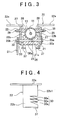
- the tilt lever 31 is operated by tilting in the other direction centering about the tilt lever shaft 25 such as in the counter-clockwise direction of FIG. 2 , tightening of the upper bracket 22 to both sidewall portions 22b is released, the locked state of the distance bracket 21 is released, and the angle of the column tube 11 can be adjusted.
- a locking mechanism 33 that locks and unlocks the distance bracket 21 to and from the upper bracket 22 is composed by the threaded portion 25b of the tilt lever shaft 25 and the nut 32 of the tilt lever 31.
- An urging member in the form of a torque spring 35 is attached to the pivot shaft 29, and one end of this torque spring 35 is fastened to the pivot shaft 29, while the other end is fastened to the link member 27.
- the torque spring 35 constantly imparts an urging force to the link member 27 in the direction in which the tilt lever shaft 25 engages with the engaging portion 30 of the upper bracket 22, or in other words, urging force in the clockwise direction of FIG. 2 .
- a limiting portion 37 respectively provided on both sidewall portions 22b of the upper bracket 22 defines a lower limit of a range of movement of the distance bracket 21 and limits the amount by which the distance bracket 21 moves downward by contacting the lower surface thereof when the distance bracket 21 has been lowered by a prescribed amount together with the column tube 11.
- the tilt lever 31 When the tilt lever 31 is then operated by pulling in the direction in which the tilt lever shaft 25 disengages from the engaging portion 30 of the upper bracket 22 (direction indicated by the arrow in FIG. 2 ) in opposition to the urging force of the torque spring 35 while in this state, the link member 27 is tilted about the center of the pivot shafts 29 in the clockwise direction of FIG. 2 . As a result, the tilt lever shaft 25 moves along the slot 26 of the distance bracket 21, and as shown in FIG. 5 , is disengaged from the grooves 30a of the upper bracket 22. In this case, by moving the tilt lever shaft 25 to the position where it contacts the end portion of the slot 26 of the distance bracket 21 (state shown in FIG. 5 ), the tilt lever shaft 25 can be disengaged from the grooves 30a of the upper bracket 22 without having to operate the tilt lever 31 beyond that which is necessary.
- both sidewall portions 22b of the upper bracket 22 are tightened by the threading interaction between the nut 32 of the tilt lever 31 and the threaded portion 25b of the tilt lever shaft 25.
- the distance bracket 21 is locked to the upper bracket 22 in a state in which the column tube 11 is held at a prescribed tilting angle position.
- the tilt lever 31 and the like while the tilt lever shaft 25 is disengaged from the engaging portion 30 of the upper bracket 22 although there is the possibility of the column tube 11 moving downward due to its own weight, the amount of downward movement of the column tube 11 is limited as a result of the distance bracket 21 contacting the limiting portion 37 provided on the upper bracket 22.
- the engaging portion 30, composed of a plurality of grooves 30a that removably engage with the tilt lever shaft 25, is provided on the upper bracket 22, the link member 27 is rotatably supported by the column tube 11, and the tilt lever shaft 25 is attached to the link member 27 so as to engage with and disengage from the engaging portion 30 of the upper bracket 22 by pivoting of the link member 27.
- the steering wheel 14 and the column tube 11 do not move downward by their own weight due to engagement of the tilt lever shaft 25 and the engaging portion 30 even if the locked state of the distance bracket 21 is released, and the steering wheel 14 and the column tube 11 can be reliably held at a tilting angle position prior to releasing the lock.
- the tilt lever shaft 25 engages with the grooves 30a while in the locked state, the tilt position is held even during secondary collisions, thereby improving the impact absorption performance of an air bag and the like.
- the tilt lever bracket 25 is able to smoothly engage with the grooves 30a regardless of the position of the steering wheel 14 in the up-down direction.
- the shape of the engaging portion 30 may of any shape provided it is able to removably engage the tilt lever shaft 25, and the engaged state with the tilt lever shaft 25 can be maintained even if tightening of the distance bracket 21 to the upper bracket 22 is released.
- tilt lever shaft 25 is restricted from rotating relative to the link member 27 in the embodiment described above, it can also be restricted from rotating relative to the distance bracket 21 or the upper bracket 22, and is not limited to that described in the above-mentioned embodiment.
- the link member 27 can also be supported by a member integrated with the column tube 11 instead of by the column tube 11, and for example, may be supported by the distance bracket 21.
- a plurality of grooves (30a) that removably engage with a tilt lever shaft (25) are provided in an upper bracket (22), a link member (27) is pivotally supported with respect to a column tube (11) or a member integrated with the column tube, and the tilt lever shaft (25) is attached to the link member (27) to be able to removably engage with the grooves (30a) of the upper bracket (22) by pivoting of the link member (27).
Landscapes
- Engineering & Computer Science (AREA)
- Chemical & Material Sciences (AREA)
- Combustion & Propulsion (AREA)
- Transportation (AREA)
- Mechanical Engineering (AREA)
- Steering Controls (AREA)
- Steering Control In Accordance With Driving Conditions (AREA)
Abstract
Description
- The invention relates to a vehicle steering column provided with a tilt mechanism.
- Vehicle steering columns provided with a tilt mechanism are typically such that, after releasing a locking mechanism that holds the steering column at a tilted position by operating a tilt lever, a column tube inserted with a steering shaft is adjusted to a desired angle position by tilting about a tilting fulcrum shaft, and the locking mechanism is then locked by operating the tilt lever while in that position. An example of this type of conventional vehicle steering column is described in Japanese Patent Application Publication No.
2000-344115 JP-A-2000-344115 - In a vehicle steering column like that described in
JP-A-2000-344115 - An object of the invention is to provide a vehicle steering column capable of holding a steering column in position even after a locking mechanism has been released.
- The vehicle steering column in one aspect of the invention includes: a column tube (11) capable of pivoting about a tilting fulcrum shaft (12); an upper bracket (22) that clamps a distance bracket (21) fixed to the column tube (11) so that the distance bracket (21) is movably adjusted with respect to the upper bracket (22) in an up-down direction; a tilt lever shaft (25) that passes through the distance bracket (21); and a tilt lever (31) which is rotatably attached to the tilt lever shaft (25), and the tilt lever (31) locking and releasing the distance bracket (21) to and from the upper bracket (22). A plurality of grooves (30a) that removably engage with the tilt lever shaft (25) are provided in the upper bracket (22), a link member (27) is pivotally supported by the column tube (11) or a member integrated with the column tube (11), and the tilt lever shaft (25) is attached to the link member (27) to be removably engaged with the grooves (30a) of the upper bracket (22) by pivoting of the link member (27).
- According to the vehicle steering column in this aspect, a plurality of grooves removably engaging with a tilt lever shaft are provided in an upper bracket, a link member is pivotally supported by a column tube or a member integrated with the column tube, and a tilt lever shaft is attached to the link member to be removably engaged with the grooves of the upper bracket by pivoting of the link member. As a result, even if a lock of the distance bracket is released, the steering wheel and steering column do not move downward due to the weight thereof because of engagement between the tilt lever shaft and the grooves, thereby making it possible to reliably hold the steering wheel and the steering column at a tilting angle position prior to releasing the lock. In addition, since the tilt lever shaft engages with the grooves while locked, the tilt position is held even during secondary collisions, thereby improving the impact absorption performance of an air bag and the like.
- In addition, in the vehicle steering column in the above aspect, the grooves (30a) of the upper bracket (22) may be formed in a serrated shape.
- According to the vehicle steering column in the above aspect, since the grooves of the upper bracket are formed in a serrated shape, the tilt lever shaft is able to smoothly engage with the grooves regardless of the position of the steering wheel in the up-down direction.
- In addition, in the vehicle steering column in the above aspect, an urging member (35) that urges the link member (27) so that the tilt lever shaft (25) engages with the grooves (30a), may also be included.
- According to the vehicle steering column as claimed in the above aspect, since an urging member is included that urges the link member so that the tilt lever shaft engages with the grooves, the tilt lever shaft can be made to reliably and easily engage with the grooves by the urging force of the urging member.
- In addition, in the vehicle steering column in the above aspect, a slot (26) in which the tilt lever shaft (25) is disposed may be provided in the distance bracket (21), and a range of pivoting of the link member (27) may be limited by the slot (26).
- According to the vehicle steering column in the above aspect, since a slot in which the tilt lever shaft is disposed is provided in the distance bracket, and a range of pivoting of the link member is limited by the slot, an amount of pivoting of the link member as determined by operation of the tilt lever can be limited within the minimum required range in which the tilt lever shaft disengages from the grooves.
- The features, advantages, and technical and industrial significance of this invention will be described in the following detailed description of example embodiments of the invention with reference to the accompanying drawings, in which like numerals denote like elements, and wherein:
-
FIG. 1 is a schematic diagram showing a vehicle steering column in an embodiment of the invention; -
FIG. 2 is a side view showing the principal portion of a vehicle steering column; -
FIG. 3 is a cross-sectional view taken along line III-III ofFIG. 2 ; -
FIG. 4 is a side view of an upper bracket; and -
FIG. 5 is a drawing showing an operating state ofFIG. 2 . - The following provides an explanation of embodiments of the invention based on the drawings.
FIG. 1 shows a schematic diagram of avehicle steering column 10 in this embodiment. Acolumn tube 11 is pivotally supported by a tiltingfulcrum shaft 12 and can be adjusted by pivoting about the tiltingfulcrum shaft 12. Asteering shaft 13 is rotatably fit into a shaft center portion of thecolumn tube 11. Asteering wheel 14 is attached to one end of thesteering shaft 13. A shaft coupling in the form of anintermediate shaft 15 is coupled to the other end of thesteering shaft 13. - As shown in
FIGS. 2 and3 , adistance bracket 21 is fastened to thecolumn tube 11. Thedistance bracket 21 is clamped to anupper bracket 22 fixed to a vehicle body 23 (seeFIG. 1 ) while being allowing to move by adjustment in the up-down direction. Theupper bracket 22 has a pair of members having an L-shaped cross-section, including of aflange portion 22a extending along thecolumn tube 11 and asidewall portion 22b extending downward vertically from one end of theflange portion 22a, arranged back-to-back in bilateral symmetry, and eachflange portion 22a is fixed to thevehicle body 23 with bolts and the like. Anarcuate portion 21a is formed in a central portion of thedistance bracket 21, and the outer peripheral surface of thecolumn tube 11 is contacted by thisarcuate portion 21a and is fixed by welding and the like. Thedistance bracket 21 is arranged between bothsidewall portions 22b of theupper bracket 22, and is clamped to bothsidewall portions 22b while allowed to make sliding contact therewith. - A
slot 26 having a configuration to be described later is formed in thedistance bracket 21 and through which is inserted atilt lever shaft 25 in the horizontal direction at a right angle to the axial line of thesteering shaft 13. Thetilt lever shaft 25 is supported by alink member 27 that is pivotally supported by thecolumn tube 11 while allowing to pivot about an axial line parallel to thetilt lever shaft 25. More specifically, a pair ofsupport brackets 28 are respectively fixed to the circumferential surface of thecolumn tube 11 at a slight distance away from one end 22b1 of thesidewall portion 22b of theupper bracket 22 towards thesteering wheel 14, andpivot shafts 29 are respectively provided in thesesupport brackets 28 parallel to thetilt lever bracket 25. Thelink member 27 able to make sliding contact with each outer surface of bothsidewall portions 22b of theupper bracket 22 is supported by eachpivot shaft 29 while respectively able to pivot about an axial line parallel to thetilt lever shaft 25. Thetilt lever shaft 25 is inserted through the distal end of thelink member 27 parallel to thepivot shafts 29, and thetilt lever shaft 25 protrudes from both sides of eachlink member 27 after passing through theupper bracket 22 and thedistance bracket 21. - As shown in
FIG. 4 , anengaging portion 30, consisting of a plurality ofgrooves 30a cut out into a serrated shape that open towards the one end 22b1 on the side of thesteering wheel 14, is formed in bothsidewall portions 22b of theupper bracket 22, and thetilt lever shaft 25 is removably engaged with thesegrooves 30a by tilting of thelink member 27. In order to removably engage thetilt lever shaft 25 with theengaging portion 30 by tilting thelink member 27, thegrooves 30a of theengaging portion 30 formed in bothsidewall portions 22b of theupper bracket 22 are formed into a V-shape along an arcuate locus centered about thepivot shafts 29. In addition, theslot 26 formed in thedistance bracket 21 is formed in an arc centering about thepivot shafts 29 or in a straight line approximating this arc. The amount of movement of thetilt lever shaft 25, or in other words, the amount of tilting of thelink member 27, is restricted by thisslot 26, and pivoting of thelink member 27 is restricted at the position where thetilt lever shaft 25 has disengaged from theengaging portion 30. - The
tilt lever shaft 25 protrudes from thelink member 27 on both sides after passing through theslot 26 formed in thedistance bracket 21 and thegrooves 30a formed in bothsidewall portions 22b of theupper bracket 22. A flange-shaped head portion 25a that contacts an end surface of onelink member 27 is formed on one of the protruding ends of thetilt lever shaft 25, while a threadedportion 25b is formed on the other protruding end. Anut 32 integrally provided on thetilt lever 31 is screwed onto the threadedportion 25b. Thetilt lever shaft 25 is prevented from turning by engaging with the serrations in thelink members 27 on both sides. - As a result, when the
tilt lever 31 is operated by tilting in one direction centering about thetilt lever shaft 25 such as in the clockwise direction inFIG. 2 , bothsidewall portions 22b of theupper bracket 22 are tightened by threading interaction between the threadedportion 25b of thetilt lever shaft 25 and thenut 32 of thetilt lever 31, and thedistance bracket 21 clamped between bothsidewall portions 22b is locked in position. In addition, when thetilt lever 31 is operated by tilting in the other direction centering about thetilt lever shaft 25 such as in the counter-clockwise direction ofFIG. 2 , tightening of theupper bracket 22 to bothsidewall portions 22b is released, the locked state of thedistance bracket 21 is released, and the angle of thecolumn tube 11 can be adjusted. Alocking mechanism 33 that locks and unlocks thedistance bracket 21 to and from theupper bracket 22 is composed by the threadedportion 25b of thetilt lever shaft 25 and thenut 32 of thetilt lever 31. - An urging member in the form of a
torque spring 35 is attached to thepivot shaft 29, and one end of thistorque spring 35 is fastened to thepivot shaft 29, while the other end is fastened to thelink member 27. Thetorque spring 35 constantly imparts an urging force to thelink member 27 in the direction in which thetilt lever shaft 25 engages with theengaging portion 30 of theupper bracket 22, or in other words, urging force in the clockwise direction ofFIG. 2 . - Furthermore, in
FIGS. 2 ,3 and 4 , a limitingportion 37 respectively provided on bothsidewall portions 22b of theupper bracket 22 defines a lower limit of a range of movement of thedistance bracket 21 and limits the amount by which thedistance bracket 21 moves downward by contacting the lower surface thereof when thedistance bracket 21 has been lowered by a prescribed amount together with thecolumn tube 11. - Next, an explanation is provided of operation of this embodiment configured in the manner described above. Normally, the
tilt lever shaft 25 is engaged with acertain groove 30a of theupper bracket 22 as shown inFIG 2 by urging force of thetorque spring 35 that acts on thelink member 27. In addition, thedistance bracket 21 and theupper bracket 22 are locked by thelocking mechanism 33, and thesteering wheel 14 and thecolumn tube 11 are held at a prescribed tilting angle position. - In the case of adjusting the position of the
steering wheel 14 to a desired position in the up-down direction from this state, when thetilt lever 31 is first operated by tilting about thetilt lever shaft 25 such as in the counter-clockwise direction inFIG. 2 , tightening of bothsidewalls 22b of theupper bracket 22 is released by threading interaction between thenut 32 of thetilt lever 31 and the threadedportion 25b of thetilt lever shaft 25, thereby unlocking thedistance bracket 21. At this time, even if the hand is taken away from thetilt lever 31, since thetilt lever shaft 25 is engaged with thegrooves 30a of theupper bracket 22, thesteering wheel 14 and thecolumn tube 11 do not move downward due to the weight thereof, and thesteering wheel 14 and thecolumn tube 11 can be reliably held at the tilting angle position prior to unlocking thedistance bracket 21. - When the
tilt lever 31 is then operated by pulling in the direction in which thetilt lever shaft 25 disengages from theengaging portion 30 of the upper bracket 22 (direction indicated by the arrow inFIG. 2 ) in opposition to the urging force of thetorque spring 35 while in this state, thelink member 27 is tilted about the center of thepivot shafts 29 in the clockwise direction ofFIG. 2 . As a result, thetilt lever shaft 25 moves along theslot 26 of thedistance bracket 21, and as shown inFIG. 5 , is disengaged from thegrooves 30a of theupper bracket 22. In this case, by moving thetilt lever shaft 25 to the position where it contacts the end portion of theslot 26 of the distance bracket 21 (state shown inFIG. 5 ), thetilt lever shaft 25 can be disengaged from thegrooves 30a of theupper bracket 22 without having to operate thetilt lever 31 beyond that which is necessary. - While in this state, after the
steering wheel 14 is moved by an amount desired to be adjusted either in the upward or downward direction in which tilt is desired to be adjusted, when the pulling operating force applied to thetilt lever 31 is removed, thelink member 27 is pivoted in the clockwise direction ofFIG. 5 centering about thepivot shafts 29 by the urging force of thecoil spring 35, thereby enabling thetilt lever shaft 25 is be reliably and easily engaged with adifferent groove 30a of the engagingportion 30 of theupper bracket 22. As a result, thecolumn tube 11 can be held at a prescribed tilting angle position. At this time, since the engagingportion 30 of theupper bracket 22 is formed in a serrated shape, thetilt lever shaft 25 can be smoothly engaged with the engaging portion 30 (grooves 30a) regardless of the position of thesteering wheel 14 in the up-down direction. - Subsequently, by operating the
tilt lever 31 by tilting in the opposition direction of that indicated above (for example, the clockwise direction ofFIG 2 ) centering about thetilt lever shaft 25, bothsidewall portions 22b of theupper bracket 22 are tightened by the threading interaction between thenut 32 of thetilt lever 31 and the threadedportion 25b of thetilt lever shaft 25. As a result, thedistance bracket 21 is locked to theupper bracket 22 in a state in which thecolumn tube 11 is held at a prescribed tilting angle position. - Furthermore, in the case a hand is mistakenly released from the
steering wheel 14, thetilt lever 31 and the like while thetilt lever shaft 25 is disengaged from the engagingportion 30 of theupper bracket 22, although there is the possibility of thecolumn tube 11 moving downward due to its own weight, the amount of downward movement of thecolumn tube 11 is limited as a result of thedistance bracket 21 contacting the limitingportion 37 provided on theupper bracket 22. - According to this embodiment as described above, the engaging
portion 30, composed of a plurality ofgrooves 30a that removably engage with thetilt lever shaft 25, is provided on theupper bracket 22, thelink member 27 is rotatably supported by thecolumn tube 11, and thetilt lever shaft 25 is attached to thelink member 27 so as to engage with and disengage from the engagingportion 30 of theupper bracket 22 by pivoting of thelink member 27. As a result, thesteering wheel 14 and thecolumn tube 11 do not move downward by their own weight due to engagement of thetilt lever shaft 25 and the engagingportion 30 even if the locked state of thedistance bracket 21 is released, and thesteering wheel 14 and thecolumn tube 11 can be reliably held at a tilting angle position prior to releasing the lock. In addition, since thetilt lever shaft 25 engages with thegrooves 30a while in the locked state, the tilt position is held even during secondary collisions, thereby improving the impact absorption performance of an air bag and the like. - Moreover, since the engaging
portion 30 of theupper bracket 22 is composed by thegrooves 30a formed into a serrated shape, thetilt lever bracket 25 is able to smoothly engage with thegrooves 30a regardless of the position of thesteering wheel 14 in the up-down direction. - Although the embodiment described above describes an example in which the engaging
portion 30 composed of a plurality ofserrated grooves 30a is formed in theupper bracket 22, the shape of the engagingportion 30 may of any shape provided it is able to removably engage thetilt lever shaft 25, and the engaged state with thetilt lever shaft 25 can be maintained even if tightening of thedistance bracket 21 to theupper bracket 22 is released. - In addition, although the
tilt lever shaft 25 is restricted from rotating relative to thelink member 27 in the embodiment described above, it can also be restricted from rotating relative to thedistance bracket 21 or theupper bracket 22, and is not limited to that described in the above-mentioned embodiment. - In addition, although the embodiment described above describes an example in which locking and unlocking of the
distance bracket 21 to and from theupper bracket 22 is carried out by a screw mechanism composed of the threadedportion 25b and thenut 32, this can also be carried out with a cam mechanism instead of the screw mechanism. - Moreover, although the embodiment described above describes an example in which the
link member 27, which supports thetilt lever shaft 25 that engages with and disengages from the engagingportion 30 provided on theupper bracket 22, is tiltably supported by thecolumn tube 11, thelink member 27 can also be supported by a member integrated with thecolumn tube 11 instead of by thecolumn tube 11, and for example, may be supported by thedistance bracket 21. - Although the above has provided an explanation of embodiments of the invention, the invention is not limited to the above-mentioned embodiments, but rather can naturally be modified in various ways within a range that does not deviate from the gist thereof.
A plurality of grooves (30a) that removably engage with a tilt lever shaft (25) are provided in an upper bracket (22), a link member (27) is pivotally supported with respect to a column tube (11) or a member integrated with the column tube, and the tilt lever shaft (25) is attached to the link member (27) to be able to removably engage with the grooves (30a) of the upper bracket (22) by pivoting of the link member (27).
Claims (5)
- A vehicle steering column, characterized by comprising:a column tube (11) capable of pivoting about a tilting fulcrum shaft (12);an upper bracket (22) that clamps a distance bracket (21) fixed to the column tube (11) so that the distance bracket (21) is movably adjusted with respect to the upper bracket (22) in an up-down direction;a tilt lever shaft (25) that passes through the distance bracket (21); anda tilt lever (31) which is rotatably attached to the tilt lever shaft (25), and the tilt lever (31) locking and releasing the distance bracket (21) to and from the upper bracket (22), whereina plurality of grooves (30a) that removably engage with the tilt lever shaft (25) are provided in the upper bracket (22),a link member (27) is pivotally supported by the column tube (11) or a member integrated with the column tube (11), andthe tilt lever shaft (25) is attached to the link member (27) to be removably engaged with the grooves (30a) of the upper bracket (22) by pivoting of the link member (27).
- The vehicle steering column according to claim 1, wherein
the grooves (30a) of the upper bracket (22) are formed in a serrated shape. - The vehicle steering column according to claim 1 or 2, further comprising
an urging member (35) that urges the link member (27) so that the tilt lever shaft (25) engages with the grooves (30a). - The vehicle steering column according to any one of claims 1 to 3, wherein
a slot (26), in which the tilt lever shaft (25) is disposed, is provided in the distance bracket (21), and a range of pivoting of the link member (27) is limited by the slot (26). - The vehicle steering column according to any one of claims 1 to 4, further comprising
a limiting portion (37) that defines a lower limit of a range of movement of the distance bracket (21).
Applications Claiming Priority (1)
| Application Number | Priority Date | Filing Date | Title |
|---|---|---|---|
| JP2008205460A JP2010036849A (en) | 2008-08-08 | 2008-08-08 | Steering column for vehicle |
Publications (2)
| Publication Number | Publication Date |
|---|---|
| EP2154048A1 true EP2154048A1 (en) | 2010-02-17 |
| EP2154048B1 EP2154048B1 (en) | 2011-02-23 |
Family
ID=41228711
Family Applications (1)
| Application Number | Title | Priority Date | Filing Date |
|---|---|---|---|
| EP09167454A Not-in-force EP2154048B1 (en) | 2008-08-08 | 2009-08-07 | Vehicle steering column |
Country Status (4)
| Country | Link |
|---|---|
| EP (1) | EP2154048B1 (en) |
| JP (1) | JP2010036849A (en) |
| AT (1) | ATE499267T1 (en) |
| DE (1) | DE602009000779D1 (en) |
Citations (2)
| Publication number | Priority date | Publication date | Assignee | Title |
|---|---|---|---|---|
| US5409261A (en) * | 1992-08-06 | 1995-04-25 | Nsk Ltd. | Tilt steering system |
| JP2000344115A (en) | 1999-06-04 | 2000-12-12 | Fuji Kiko Co Ltd | Vehicle steering column |
-
2008
- 2008-08-08 JP JP2008205460A patent/JP2010036849A/en active Pending
-
2009
- 2009-08-07 EP EP09167454A patent/EP2154048B1/en not_active Not-in-force
- 2009-08-07 AT AT09167454T patent/ATE499267T1/en not_active IP Right Cessation
- 2009-08-07 DE DE602009000779T patent/DE602009000779D1/en active Active
Patent Citations (2)
| Publication number | Priority date | Publication date | Assignee | Title |
|---|---|---|---|---|
| US5409261A (en) * | 1992-08-06 | 1995-04-25 | Nsk Ltd. | Tilt steering system |
| JP2000344115A (en) | 1999-06-04 | 2000-12-12 | Fuji Kiko Co Ltd | Vehicle steering column |
Also Published As
| Publication number | Publication date |
|---|---|
| JP2010036849A (en) | 2010-02-18 |
| EP2154048B1 (en) | 2011-02-23 |
| DE602009000779D1 (en) | 2011-04-07 |
| ATE499267T1 (en) | 2011-03-15 |
Similar Documents
| Publication | Publication Date | Title |
|---|---|---|
| JP5750949B2 (en) | Vehicle steering device | |
| EP2431257B1 (en) | Steering device | |
| EP2607207B1 (en) | Steering device | |
| JP4932388B2 (en) | Movable steering device | |
| JP5595807B2 (en) | Steering column device | |
| JP2017144968A (en) | Steering device | |
| JP2017140988A (en) | Steering device | |
| EP1975036A2 (en) | Lock mechanism for an adjustable steering column assembly | |
| US6591709B1 (en) | Linear tilt mechanism | |
| JP6428487B2 (en) | Vehicle seat locking device | |
| JP6403333B2 (en) | Steering device | |
| EP2154048B1 (en) | Vehicle steering column | |
| JP4390566B2 (en) | Steering device | |
| JP5181584B2 (en) | Steering device | |
| JP2004136870A (en) | Tilt steering device | |
| JP3716628B2 (en) | Tilt and telescopic steering device | |
| JP2010083227A (en) | Steering column device | |
| JP5176888B2 (en) | Electric tilt steering device | |
| JP2022189047A (en) | steering device | |
| EP2937264B1 (en) | Steering device | |
| JP6480136B2 (en) | Steering column device for forklift | |
| JPH0367779A (en) | Tilt steering device | |
| JP7836860B2 (en) | Bicycle carrier | |
| JP7836861B2 (en) | Bicycle carrier | |
| JP2009006740A (en) | Steering device |
Legal Events
| Date | Code | Title | Description |
|---|---|---|---|
| PUAI | Public reference made under article 153(3) epc to a published international application that has entered the european phase |
Free format text: ORIGINAL CODE: 0009012 |
|
| AK | Designated contracting states |
Kind code of ref document: A1 Designated state(s): AT BE BG CH CY CZ DE DK EE ES FI FR GB GR HR HU IE IS IT LI LT LU LV MC MK MT NL NO PL PT RO SE SI SK SM TR |
|
| GRAP | Despatch of communication of intention to grant a patent |
Free format text: ORIGINAL CODE: EPIDOSNIGR1 |
|
| 17P | Request for examination filed |
Effective date: 20100720 |
|
| GRAS | Grant fee paid |
Free format text: ORIGINAL CODE: EPIDOSNIGR3 |
|
| GRAA | (expected) grant |
Free format text: ORIGINAL CODE: 0009210 |
|
| AK | Designated contracting states |
Kind code of ref document: B1 Designated state(s): AT BE BG CH CY CZ DE DK EE ES FI FR GB GR HR HU IE IS IT LI LT LU LV MC MK MT NL NO PL PT RO SE SI SK SM TR |
|
| REG | Reference to a national code |
Ref country code: GB Ref legal event code: FG4D |
|
| REG | Reference to a national code |
Ref country code: CH Ref legal event code: EP |
|
| REG | Reference to a national code |
Ref country code: IE Ref legal event code: FG4D |
|
| REF | Corresponds to: |
Ref document number: 602009000779 Country of ref document: DE Date of ref document: 20110407 Kind code of ref document: P |
|
| REG | Reference to a national code |
Ref country code: DE Ref legal event code: R096 Ref document number: 602009000779 Country of ref document: DE Effective date: 20110407 |
|
| REG | Reference to a national code |
Ref country code: NL Ref legal event code: VDEP Effective date: 20110223 |
|
| LTIE | Lt: invalidation of european patent or patent extension |
Effective date: 20110223 |
|
| PG25 | Lapsed in a contracting state [announced via postgrant information from national office to epo] |
Ref country code: LT Free format text: LAPSE BECAUSE OF FAILURE TO SUBMIT A TRANSLATION OF THE DESCRIPTION OR TO PAY THE FEE WITHIN THE PRESCRIBED TIME-LIMIT Effective date: 20110223 Ref country code: ES Free format text: LAPSE BECAUSE OF FAILURE TO SUBMIT A TRANSLATION OF THE DESCRIPTION OR TO PAY THE FEE WITHIN THE PRESCRIBED TIME-LIMIT Effective date: 20110603 Ref country code: NO Free format text: LAPSE BECAUSE OF FAILURE TO SUBMIT A TRANSLATION OF THE DESCRIPTION OR TO PAY THE FEE WITHIN THE PRESCRIBED TIME-LIMIT Effective date: 20110523 Ref country code: SE Free format text: LAPSE BECAUSE OF FAILURE TO SUBMIT A TRANSLATION OF THE DESCRIPTION OR TO PAY THE FEE WITHIN THE PRESCRIBED TIME-LIMIT Effective date: 20110223 Ref country code: LV Free format text: LAPSE BECAUSE OF FAILURE TO SUBMIT A TRANSLATION OF THE DESCRIPTION OR TO PAY THE FEE WITHIN THE PRESCRIBED TIME-LIMIT Effective date: 20110223 Ref country code: GR Free format text: LAPSE BECAUSE OF FAILURE TO SUBMIT A TRANSLATION OF THE DESCRIPTION OR TO PAY THE FEE WITHIN THE PRESCRIBED TIME-LIMIT Effective date: 20110524 Ref country code: HR Free format text: LAPSE BECAUSE OF FAILURE TO SUBMIT A TRANSLATION OF THE DESCRIPTION OR TO PAY THE FEE WITHIN THE PRESCRIBED TIME-LIMIT Effective date: 20110223 Ref country code: PT Free format text: LAPSE BECAUSE OF FAILURE TO SUBMIT A TRANSLATION OF THE DESCRIPTION OR TO PAY THE FEE WITHIN THE PRESCRIBED TIME-LIMIT Effective date: 20110623 |
|
| PG25 | Lapsed in a contracting state [announced via postgrant information from national office to epo] |
Ref country code: FI Free format text: LAPSE BECAUSE OF FAILURE TO SUBMIT A TRANSLATION OF THE DESCRIPTION OR TO PAY THE FEE WITHIN THE PRESCRIBED TIME-LIMIT Effective date: 20110223 Ref country code: NL Free format text: LAPSE BECAUSE OF FAILURE TO SUBMIT A TRANSLATION OF THE DESCRIPTION OR TO PAY THE FEE WITHIN THE PRESCRIBED TIME-LIMIT Effective date: 20110223 Ref country code: BE Free format text: LAPSE BECAUSE OF FAILURE TO SUBMIT A TRANSLATION OF THE DESCRIPTION OR TO PAY THE FEE WITHIN THE PRESCRIBED TIME-LIMIT Effective date: 20110223 Ref country code: AT Free format text: LAPSE BECAUSE OF FAILURE TO SUBMIT A TRANSLATION OF THE DESCRIPTION OR TO PAY THE FEE WITHIN THE PRESCRIBED TIME-LIMIT Effective date: 20110223 Ref country code: CY Free format text: LAPSE BECAUSE OF FAILURE TO SUBMIT A TRANSLATION OF THE DESCRIPTION OR TO PAY THE FEE WITHIN THE PRESCRIBED TIME-LIMIT Effective date: 20110223 Ref country code: SI Free format text: LAPSE BECAUSE OF FAILURE TO SUBMIT A TRANSLATION OF THE DESCRIPTION OR TO PAY THE FEE WITHIN THE PRESCRIBED TIME-LIMIT Effective date: 20110223 Ref country code: BG Free format text: LAPSE BECAUSE OF FAILURE TO SUBMIT A TRANSLATION OF THE DESCRIPTION OR TO PAY THE FEE WITHIN THE PRESCRIBED TIME-LIMIT Effective date: 20110523 |
|
| PG25 | Lapsed in a contracting state [announced via postgrant information from national office to epo] |
Ref country code: EE Free format text: LAPSE BECAUSE OF FAILURE TO SUBMIT A TRANSLATION OF THE DESCRIPTION OR TO PAY THE FEE WITHIN THE PRESCRIBED TIME-LIMIT Effective date: 20110223 Ref country code: DK Free format text: LAPSE BECAUSE OF FAILURE TO SUBMIT A TRANSLATION OF THE DESCRIPTION OR TO PAY THE FEE WITHIN THE PRESCRIBED TIME-LIMIT Effective date: 20110223 |
|
| PG25 | Lapsed in a contracting state [announced via postgrant information from national office to epo] |
Ref country code: SK Free format text: LAPSE BECAUSE OF FAILURE TO SUBMIT A TRANSLATION OF THE DESCRIPTION OR TO PAY THE FEE WITHIN THE PRESCRIBED TIME-LIMIT Effective date: 20110223 Ref country code: CZ Free format text: LAPSE BECAUSE OF FAILURE TO SUBMIT A TRANSLATION OF THE DESCRIPTION OR TO PAY THE FEE WITHIN THE PRESCRIBED TIME-LIMIT Effective date: 20110223 Ref country code: RO Free format text: LAPSE BECAUSE OF FAILURE TO SUBMIT A TRANSLATION OF THE DESCRIPTION OR TO PAY THE FEE WITHIN THE PRESCRIBED TIME-LIMIT Effective date: 20110223 |
|
| PGFP | Annual fee paid to national office [announced via postgrant information from national office to epo] |
Ref country code: DE Payment date: 20110830 Year of fee payment: 3 Ref country code: FR Payment date: 20110829 Year of fee payment: 3 |
|
| PG25 | Lapsed in a contracting state [announced via postgrant information from national office to epo] |
Ref country code: MT Free format text: LAPSE BECAUSE OF FAILURE TO SUBMIT A TRANSLATION OF THE DESCRIPTION OR TO PAY THE FEE WITHIN THE PRESCRIBED TIME-LIMIT Effective date: 20110223 |
|
| PLBE | No opposition filed within time limit |
Free format text: ORIGINAL CODE: 0009261 |
|
| STAA | Information on the status of an ep patent application or granted ep patent |
Free format text: STATUS: NO OPPOSITION FILED WITHIN TIME LIMIT |
|
| 26N | No opposition filed |
Effective date: 20111124 |
|
| PG25 | Lapsed in a contracting state [announced via postgrant information from national office to epo] |
Ref country code: PL Free format text: LAPSE BECAUSE OF FAILURE TO SUBMIT A TRANSLATION OF THE DESCRIPTION OR TO PAY THE FEE WITHIN THE PRESCRIBED TIME-LIMIT Effective date: 20110223 |
|
| REG | Reference to a national code |
Ref country code: DE Ref legal event code: R097 Ref document number: 602009000779 Country of ref document: DE Effective date: 20111124 |
|
| PG25 | Lapsed in a contracting state [announced via postgrant information from national office to epo] |
Ref country code: MC Free format text: LAPSE BECAUSE OF NON-PAYMENT OF DUE FEES Effective date: 20110831 |
|
| REG | Reference to a national code |
Ref country code: IE Ref legal event code: MM4A |
|
| PG25 | Lapsed in a contracting state [announced via postgrant information from national office to epo] |
Ref country code: IT Free format text: LAPSE BECAUSE OF FAILURE TO SUBMIT A TRANSLATION OF THE DESCRIPTION OR TO PAY THE FEE WITHIN THE PRESCRIBED TIME-LIMIT Effective date: 20110223 |
|
| PG25 | Lapsed in a contracting state [announced via postgrant information from national office to epo] |
Ref country code: IE Free format text: LAPSE BECAUSE OF NON-PAYMENT OF DUE FEES Effective date: 20110807 |
|
| PG25 | Lapsed in a contracting state [announced via postgrant information from national office to epo] |
Ref country code: MK Free format text: LAPSE BECAUSE OF FAILURE TO SUBMIT A TRANSLATION OF THE DESCRIPTION OR TO PAY THE FEE WITHIN THE PRESCRIBED TIME-LIMIT Effective date: 20110223 |
|
| PG25 | Lapsed in a contracting state [announced via postgrant information from national office to epo] |
Ref country code: SM Free format text: LAPSE BECAUSE OF FAILURE TO SUBMIT A TRANSLATION OF THE DESCRIPTION OR TO PAY THE FEE WITHIN THE PRESCRIBED TIME-LIMIT Effective date: 20110223 |
|
| REG | Reference to a national code |
Ref country code: FR Ref legal event code: ST Effective date: 20130430 |
|
| PG25 | Lapsed in a contracting state [announced via postgrant information from national office to epo] |
Ref country code: LU Free format text: LAPSE BECAUSE OF NON-PAYMENT OF DUE FEES Effective date: 20110807 |
|
| PG25 | Lapsed in a contracting state [announced via postgrant information from national office to epo] |
Ref country code: IS Free format text: LAPSE BECAUSE OF FAILURE TO SUBMIT A TRANSLATION OF THE DESCRIPTION OR TO PAY THE FEE WITHIN THE PRESCRIBED TIME-LIMIT Effective date: 20110223 Ref country code: DE Free format text: LAPSE BECAUSE OF NON-PAYMENT OF DUE FEES Effective date: 20130301 |
|
| PG25 | Lapsed in a contracting state [announced via postgrant information from national office to epo] |
Ref country code: FR Free format text: LAPSE BECAUSE OF NON-PAYMENT OF DUE FEES Effective date: 20120831 |
|
| REG | Reference to a national code |
Ref country code: DE Ref legal event code: R119 Ref document number: 602009000779 Country of ref document: DE Effective date: 20130301 |
|
| PG25 | Lapsed in a contracting state [announced via postgrant information from national office to epo] |
Ref country code: TR Free format text: LAPSE BECAUSE OF FAILURE TO SUBMIT A TRANSLATION OF THE DESCRIPTION OR TO PAY THE FEE WITHIN THE PRESCRIBED TIME-LIMIT Effective date: 20110223 |
|
| PG25 | Lapsed in a contracting state [announced via postgrant information from national office to epo] |
Ref country code: HU Free format text: LAPSE BECAUSE OF FAILURE TO SUBMIT A TRANSLATION OF THE DESCRIPTION OR TO PAY THE FEE WITHIN THE PRESCRIBED TIME-LIMIT Effective date: 20110223 |
|
| REG | Reference to a national code |
Ref country code: CH Ref legal event code: PL |
|
| GBPC | Gb: european patent ceased through non-payment of renewal fee |
Effective date: 20130807 |
|
| PG25 | Lapsed in a contracting state [announced via postgrant information from national office to epo] |
Ref country code: CH Free format text: LAPSE BECAUSE OF NON-PAYMENT OF DUE FEES Effective date: 20130831 Ref country code: LI Free format text: LAPSE BECAUSE OF NON-PAYMENT OF DUE FEES Effective date: 20130831 |
|
| PG25 | Lapsed in a contracting state [announced via postgrant information from national office to epo] |
Ref country code: GB Free format text: LAPSE BECAUSE OF NON-PAYMENT OF DUE FEES Effective date: 20130807 |