EP2153872A1 - Method to mitigate the consequences of an unconfined or partially confined vapor cloud explosion - Google Patents
Method to mitigate the consequences of an unconfined or partially confined vapor cloud explosion Download PDFInfo
- Publication number
- EP2153872A1 EP2153872A1 EP08160954A EP08160954A EP2153872A1 EP 2153872 A1 EP2153872 A1 EP 2153872A1 EP 08160954 A EP08160954 A EP 08160954A EP 08160954 A EP08160954 A EP 08160954A EP 2153872 A1 EP2153872 A1 EP 2153872A1
- Authority
- EP
- European Patent Office
- Prior art keywords
- flame
- explosion
- release
- flammable
- acceleration suppression
- Prior art date
- Legal status (The legal status is an assumption and is not a legal conclusion. Google has not performed a legal analysis and makes no representation as to the accuracy of the status listed.)
- Withdrawn
Links
- 238000004880 explosion Methods 0.000 title claims abstract description 60
- 238000000034 method Methods 0.000 title claims abstract description 15
- 230000001629 suppression Effects 0.000 claims abstract description 50
- 230000001133 acceleration Effects 0.000 claims abstract description 46
- 239000000203 mixture Substances 0.000 claims abstract description 15
- 230000009172 bursting Effects 0.000 claims description 4
- 238000012360 testing method Methods 0.000 description 51
- 239000007789 gas Substances 0.000 description 46
- 239000000047 product Substances 0.000 description 36
- 239000003112 inhibitor Substances 0.000 description 27
- ATUOYWHBWRKTHZ-UHFFFAOYSA-N Propane Chemical compound CCC ATUOYWHBWRKTHZ-UHFFFAOYSA-N 0.000 description 20
- 238000004200 deflagration Methods 0.000 description 20
- XLYOFNOQVPJJNP-UHFFFAOYSA-N water Substances O XLYOFNOQVPJJNP-UHFFFAOYSA-N 0.000 description 13
- IJGRMHOSHXDMSA-UHFFFAOYSA-N Atomic nitrogen Chemical compound N#N IJGRMHOSHXDMSA-UHFFFAOYSA-N 0.000 description 12
- 239000003795 chemical substances by application Substances 0.000 description 12
- 239000000463 material Substances 0.000 description 12
- 150000003254 radicals Chemical class 0.000 description 12
- 230000000116 mitigating effect Effects 0.000 description 11
- 239000000126 substance Substances 0.000 description 11
- VNWKTOKETHGBQD-UHFFFAOYSA-N methane Chemical compound C VNWKTOKETHGBQD-UHFFFAOYSA-N 0.000 description 10
- 239000001294 propane Substances 0.000 description 10
- 239000006185 dispersion Substances 0.000 description 9
- 239000002360 explosive Substances 0.000 description 8
- UIIMBOGNXHQVGW-UHFFFAOYSA-M sodium bicarbonate Substances [Na+].OC([O-])=O UIIMBOGNXHQVGW-UHFFFAOYSA-M 0.000 description 8
- 239000000356 contaminant Substances 0.000 description 7
- -1 formaldehyde Natural products 0.000 description 7
- FAPWRFPIFSIZLT-UHFFFAOYSA-M Sodium chloride Chemical compound [Na+].[Cl-] FAPWRFPIFSIZLT-UHFFFAOYSA-M 0.000 description 6
- 230000004913 activation Effects 0.000 description 6
- 238000002485 combustion reaction Methods 0.000 description 6
- 238000002474 experimental method Methods 0.000 description 6
- 229910052757 nitrogen Inorganic materials 0.000 description 6
- 229910000028 potassium bicarbonate Inorganic materials 0.000 description 6
- 150000003839 salts Chemical class 0.000 description 6
- OFBQJSOFQDEBGM-UHFFFAOYSA-N Pentane Chemical compound CCCCC OFBQJSOFQDEBGM-UHFFFAOYSA-N 0.000 description 5
- 150000001875 compounds Chemical class 0.000 description 5
- 230000000694 effects Effects 0.000 description 5
- 239000011888 foil Substances 0.000 description 5
- 239000011736 potassium bicarbonate Substances 0.000 description 5
- TYJJADVDDVDEDZ-UHFFFAOYSA-M potassium hydrogencarbonate Chemical compound [K+].OC([O-])=O TYJJADVDDVDEDZ-UHFFFAOYSA-M 0.000 description 5
- QVGXLLKOCUKJST-UHFFFAOYSA-N atomic oxygen Chemical compound [O] QVGXLLKOCUKJST-UHFFFAOYSA-N 0.000 description 4
- 238000006243 chemical reaction Methods 0.000 description 4
- 239000007788 liquid Substances 0.000 description 4
- 238000004519 manufacturing process Methods 0.000 description 4
- 239000003595 mist Substances 0.000 description 4
- 239000001301 oxygen Substances 0.000 description 4
- 229910052760 oxygen Inorganic materials 0.000 description 4
- 235000015497 potassium bicarbonate Nutrition 0.000 description 4
- 239000000843 powder Substances 0.000 description 4
- 229910000030 sodium bicarbonate Inorganic materials 0.000 description 4
- CDBYLPFSWZWCQE-UHFFFAOYSA-L sodium carbonate Substances [Na+].[Na+].[O-]C([O-])=O CDBYLPFSWZWCQE-UHFFFAOYSA-L 0.000 description 4
- ZWEHNKRNPOVVGH-UHFFFAOYSA-N 2-Butanone Chemical compound CCC(C)=O ZWEHNKRNPOVVGH-UHFFFAOYSA-N 0.000 description 3
- CSCPPACGZOOCGX-UHFFFAOYSA-N Acetone Chemical compound CC(C)=O CSCPPACGZOOCGX-UHFFFAOYSA-N 0.000 description 3
- UHOVQNZJYSORNB-UHFFFAOYSA-N Benzene Chemical compound C1=CC=CC=C1 UHOVQNZJYSORNB-UHFFFAOYSA-N 0.000 description 3
- XEKOWRVHYACXOJ-UHFFFAOYSA-N Ethyl acetate Chemical compound CCOC(C)=O XEKOWRVHYACXOJ-UHFFFAOYSA-N 0.000 description 3
- OKKJLVBELUTLKV-UHFFFAOYSA-N Methanol Chemical compound OC OKKJLVBELUTLKV-UHFFFAOYSA-N 0.000 description 3
- YXFVVABEGXRONW-UHFFFAOYSA-N Toluene Chemical compound CC1=CC=CC=C1 YXFVVABEGXRONW-UHFFFAOYSA-N 0.000 description 3
- 238000009826 distribution Methods 0.000 description 3
- VLKZOEOYAKHREP-UHFFFAOYSA-N n-Hexane Chemical compound CCCCCC VLKZOEOYAKHREP-UHFFFAOYSA-N 0.000 description 3
- 230000001681 protective effect Effects 0.000 description 3
- 235000017557 sodium bicarbonate Nutrition 0.000 description 3
- 239000011780 sodium chloride Substances 0.000 description 3
- 239000004094 surface-active agent Substances 0.000 description 3
- VTYYLEPIZMXCLO-UHFFFAOYSA-L Calcium carbonate Chemical compound [Ca+2].[O-]C([O-])=O VTYYLEPIZMXCLO-UHFFFAOYSA-L 0.000 description 2
- RTZKZFJDLAIYFH-UHFFFAOYSA-N Diethyl ether Chemical compound CCOCC RTZKZFJDLAIYFH-UHFFFAOYSA-N 0.000 description 2
- KRHYYFGTRYWZRS-UHFFFAOYSA-N Fluorane Chemical compound F KRHYYFGTRYWZRS-UHFFFAOYSA-N 0.000 description 2
- OAKJQQAXSVQMHS-UHFFFAOYSA-N Hydrazine Chemical compound NN OAKJQQAXSVQMHS-UHFFFAOYSA-N 0.000 description 2
- IMNFDUFMRHMDMM-UHFFFAOYSA-N N-Heptane Chemical compound CCCCCCC IMNFDUFMRHMDMM-UHFFFAOYSA-N 0.000 description 2
- 229910052782 aluminium Inorganic materials 0.000 description 2
- XAGFODPZIPBFFR-UHFFFAOYSA-N aluminium Chemical compound [Al] XAGFODPZIPBFFR-UHFFFAOYSA-N 0.000 description 2
- 239000003963 antioxidant agent Substances 0.000 description 2
- 235000006708 antioxidants Nutrition 0.000 description 2
- 230000015572 biosynthetic process Effects 0.000 description 2
- 239000012159 carrier gas Substances 0.000 description 2
- 238000001514 detection method Methods 0.000 description 2
- 239000012895 dilution Substances 0.000 description 2
- 238000010790 dilution Methods 0.000 description 2
- 230000007613 environmental effect Effects 0.000 description 2
- 238000011049 filling Methods 0.000 description 2
- 239000001257 hydrogen Substances 0.000 description 2
- 229910052739 hydrogen Inorganic materials 0.000 description 2
- 229910000040 hydrogen fluoride Inorganic materials 0.000 description 2
- 239000011261 inert gas Substances 0.000 description 2
- 238000009434 installation Methods 0.000 description 2
- 238000005259 measurement Methods 0.000 description 2
- 229960004624 perflexane Drugs 0.000 description 2
- ZJIJAJXFLBMLCK-UHFFFAOYSA-N perfluorohexane Chemical compound FC(F)(F)C(F)(F)C(F)(F)C(F)(F)C(F)(F)C(F)(F)F ZJIJAJXFLBMLCK-UHFFFAOYSA-N 0.000 description 2
- 229920003023 plastic Polymers 0.000 description 2
- 239000004033 plastic Substances 0.000 description 2
- 229910000029 sodium carbonate Inorganic materials 0.000 description 2
- 235000017550 sodium carbonate Nutrition 0.000 description 2
- 239000007787 solid Substances 0.000 description 2
- 239000000243 solution Substances 0.000 description 2
- 238000013022 venting Methods 0.000 description 2
- UGFAIRIUMAVXCW-UHFFFAOYSA-N Carbon monoxide Chemical compound [O+]#[C-] UGFAIRIUMAVXCW-UHFFFAOYSA-N 0.000 description 1
- OTMSDBZUPAUEDD-UHFFFAOYSA-N Ethane Chemical compound CC OTMSDBZUPAUEDD-UHFFFAOYSA-N 0.000 description 1
- VGGSQFUCUMXWEO-UHFFFAOYSA-N Ethene Chemical compound C=C VGGSQFUCUMXWEO-UHFFFAOYSA-N 0.000 description 1
- 239000005977 Ethylene Substances 0.000 description 1
- VVQNEPGJFQJSBK-UHFFFAOYSA-N Methyl methacrylate Chemical compound COC(=O)C(C)=C VVQNEPGJFQJSBK-UHFFFAOYSA-N 0.000 description 1
- CTQNGGLPUBDAKN-UHFFFAOYSA-N O-Xylene Chemical compound CC1=CC=CC=C1C CTQNGGLPUBDAKN-UHFFFAOYSA-N 0.000 description 1
- 229920005372 Plexiglas® Polymers 0.000 description 1
- 229910000831 Steel Inorganic materials 0.000 description 1
- 239000000443 aerosol Substances 0.000 description 1
- 229910052783 alkali metal Inorganic materials 0.000 description 1
- 150000001340 alkali metals Chemical class 0.000 description 1
- HSFWRNGVRCDJHI-UHFFFAOYSA-N alpha-acetylene Natural products C#C HSFWRNGVRCDJHI-UHFFFAOYSA-N 0.000 description 1
- LFVGISIMTYGQHF-UHFFFAOYSA-N ammonium dihydrogen phosphate Chemical compound [NH4+].OP(O)([O-])=O LFVGISIMTYGQHF-UHFFFAOYSA-N 0.000 description 1
- 229910000387 ammonium dihydrogen phosphate Inorganic materials 0.000 description 1
- 239000007864 aqueous solution Substances 0.000 description 1
- 125000004429 atom Chemical group 0.000 description 1
- 238000000889 atomisation Methods 0.000 description 1
- 230000008901 benefit Effects 0.000 description 1
- 239000001273 butane Substances 0.000 description 1
- 239000006227 byproduct Substances 0.000 description 1
- 229910000019 calcium carbonate Inorganic materials 0.000 description 1
- WUKWITHWXAAZEY-UHFFFAOYSA-L calcium difluoride Chemical compound [F-].[F-].[Ca+2] WUKWITHWXAAZEY-UHFFFAOYSA-L 0.000 description 1
- 229910001634 calcium fluoride Inorganic materials 0.000 description 1
- 239000002775 capsule Substances 0.000 description 1
- QGJOPFRUJISHPQ-NJFSPNSNSA-N carbon disulfide-14c Chemical compound S=[14C]=S QGJOPFRUJISHPQ-NJFSPNSNSA-N 0.000 description 1
- 229910002091 carbon monoxide Inorganic materials 0.000 description 1
- 230000015556 catabolic process Effects 0.000 description 1
- 230000006378 damage Effects 0.000 description 1
- 230000007423 decrease Effects 0.000 description 1
- 238000005474 detonation Methods 0.000 description 1
- 238000007865 diluting Methods 0.000 description 1
- 238000006073 displacement reaction Methods 0.000 description 1
- 238000010892 electric spark Methods 0.000 description 1
- 238000010304 firing Methods 0.000 description 1
- 239000012530 fluid Substances 0.000 description 1
- 231100001261 hazardous Toxicity 0.000 description 1
- 125000004435 hydrogen atom Chemical class [H]* 0.000 description 1
- 230000000977 initiatory effect Effects 0.000 description 1
- 229910052500 inorganic mineral Inorganic materials 0.000 description 1
- 238000011068 loading method Methods 0.000 description 1
- 230000007246 mechanism Effects 0.000 description 1
- 229910052751 metal Inorganic materials 0.000 description 1
- 239000002184 metal Substances 0.000 description 1
- 150000002736 metal compounds Chemical class 0.000 description 1
- 235000010755 mineral Nutrition 0.000 description 1
- 239000011707 mineral Substances 0.000 description 1
- 238000002156 mixing Methods 0.000 description 1
- 239000006012 monoammonium phosphate Substances 0.000 description 1
- 235000019837 monoammonium phosphate Nutrition 0.000 description 1
- IJDNQMDRQITEOD-UHFFFAOYSA-N n-butane Chemical compound CCCC IJDNQMDRQITEOD-UHFFFAOYSA-N 0.000 description 1
- 231100000252 nontoxic Toxicity 0.000 description 1
- 230000003000 nontoxic effect Effects 0.000 description 1
- TVMXDCGIABBOFY-UHFFFAOYSA-N octane Chemical compound CCCCCCCC TVMXDCGIABBOFY-UHFFFAOYSA-N 0.000 description 1
- 239000003973 paint Substances 0.000 description 1
- 239000002245 particle Substances 0.000 description 1
- 230000002688 persistence Effects 0.000 description 1
- 239000003208 petroleum Substances 0.000 description 1
- 230000000704 physical effect Effects 0.000 description 1
- 230000003334 potential effect Effects 0.000 description 1
- 239000002244 precipitate Substances 0.000 description 1
- 238000002360 preparation method Methods 0.000 description 1
- 239000002994 raw material Substances 0.000 description 1
- 230000009467 reduction Effects 0.000 description 1
- 238000009877 rendering Methods 0.000 description 1
- 230000004044 response Effects 0.000 description 1
- 239000012266 salt solution Substances 0.000 description 1
- 239000004065 semiconductor Substances 0.000 description 1
- 239000010959 steel Substances 0.000 description 1
- 239000000725 suspension Substances 0.000 description 1
- 231100000331 toxic Toxicity 0.000 description 1
- 230000002588 toxic effect Effects 0.000 description 1
- 238000012546 transfer Methods 0.000 description 1
- 230000007704 transition Effects 0.000 description 1
- 230000001960 triggered effect Effects 0.000 description 1
- 239000002966 varnish Substances 0.000 description 1
- 239000008096 xylene Substances 0.000 description 1
Images

Classifications
-
- A—HUMAN NECESSITIES
- A62—LIFE-SAVING; FIRE-FIGHTING
- A62C—FIRE-FIGHTING
- A62C3/00—Fire prevention, containment or extinguishing specially adapted for particular objects or places
- A62C3/06—Fire prevention, containment or extinguishing specially adapted for particular objects or places of highly inflammable material, e.g. light metals, petroleum products
-
- A—HUMAN NECESSITIES
- A62—LIFE-SAVING; FIRE-FIGHTING
- A62C—FIRE-FIGHTING
- A62C3/00—Fire prevention, containment or extinguishing specially adapted for particular objects or places
-
- A—HUMAN NECESSITIES
- A62—LIFE-SAVING; FIRE-FIGHTING
- A62C—FIRE-FIGHTING
- A62C35/00—Permanently-installed equipment
- A62C35/02—Permanently-installed equipment with containers for delivering the extinguishing substance
- A62C35/11—Permanently-installed equipment with containers for delivering the extinguishing substance controlled by a signal from the danger zone
- A62C35/13—Permanently-installed equipment with containers for delivering the extinguishing substance controlled by a signal from the danger zone with a finite supply of extinguishing material
-
- A—HUMAN NECESSITIES
- A62—LIFE-SAVING; FIRE-FIGHTING
- A62C—FIRE-FIGHTING
- A62C37/00—Control of fire-fighting equipment
- A62C37/04—Control of fire-fighting equipment with electrically-controlled release
-
- A—HUMAN NECESSITIES
- A62—LIFE-SAVING; FIRE-FIGHTING
- A62C—FIRE-FIGHTING
- A62C99/00—Subject matter not provided for in other groups of this subclass
-
- A—HUMAN NECESSITIES
- A62—LIFE-SAVING; FIRE-FIGHTING
- A62C—FIRE-FIGHTING
- A62C99/00—Subject matter not provided for in other groups of this subclass
- A62C99/0009—Methods of extinguishing or preventing the spread of fire by cooling down or suffocating the flames
- A62C99/0045—Methods of extinguishing or preventing the spread of fire by cooling down or suffocating the flames using solid substances, e.g. sand, ashes; using substances forming a crust
-
- A—HUMAN NECESSITIES
- A62—LIFE-SAVING; FIRE-FIGHTING
- A62C—FIRE-FIGHTING
- A62C99/00—Subject matter not provided for in other groups of this subclass
- A62C99/009—Methods or equipment not provided for in groups A62C99/0009 - A62C99/0081
Definitions
- the present invention is a method to mitigate the consequences of an unconfined or partially confined vapor cloud explosion.
- a particular hazard for petrochemical plants and refineries is an accidental release of a large quantity of flammable material resulting in the formation of a flammable cloud within the installation.
- Historical evidence has shown that the ignition of such a cloud can lead to a devastating explosion and a total destruction of the installation.
- Such accidents are commonly named “Vapor Cloud Explosions” (VCE) or "unconfined vapor cloud explosion” and referred as "VCE”.
- US 7153446 provides a fire or explosion suppression agent, having two suppressant parts, one comprising an explosion suppressing chemical substance which is substantially liquid at normal temperatures and pressures and the other comprising a fire or explosion suppressing inert gas; the chemical substance being dispersed as a suspension in the inert gas, the chemical substance when so disposed having low environmental impact, with a short atmospheric lifetime of less than 30 days; the chemical substance comprising one or more specific halogenated chemicals. It is not clear wether the fire or explosion suppression agent is released before or after the fire is initiated. The description mentions only the protection of a specified space or volume such as the interior of a vehicle or a volume within an aircraft.
- EP 562756 discloses a fire extinguishing and explosion suppression agent comprising perfluorohexane discharged in atomised form, such as, for example, by means of a pressurising gas which may, for instance, be nitrogen at least partially dissolved in the perfluorohexane. It is clear from page 4 lines 23+ that the discharge of the suppressant is triggered by detection of a rise in pressure due to incipient explosion.
- US 7090028 discloses a method and apparatus for producing an extremely fine micron and sub-micron size water mist using an electronic ultrasonic device that produces the mist at ambient-pressure and delivering the mist for application in suppressing fire. From column 6 lines 50+ it is understood that the mist delivery is made after the beginning of the fire.
- WO 99-24120 describes a fire or explosion suppressant comprising water or an aqueous alkali metal salt solution together with a surfactant.
- the surfactant is selected so as to be fast-acting that is, so that upon dispersion of the water or water-based solution towards the fire or explosion (e.g. in a jet or under atomisation), the surfactant acts to produce a surface tension value which becomes low (preferably at least as low as about 25 mN/m) within the time taken for the dispersed water to reach the fire or explosion (less than 50 and preferably less than 20 milliseconds). It is not clear wether the fire or explosion suppression agent is released before or after the fire is initiated.
- WO 98-47572 describes an explosion suppression arrangement for suppressing explosions within a protected area, comprising containing means for containing explosion suppressant material and having an outlet normally closed by frangible means, a source of pressure, pressure distribution means positioned within the containing means so as to be located within explosion suppressant material therein, the distribution means being pressurised by the source upon activation thereof so as to pressurise the suppressant material and break the frangible means to cause discharge of the suppressant material through the outlet.
- the explosion suppressant material is a powder such as mono-ammonium phosphate or sodium hydrogen carbonate.
- US 2003-0000951 provides a method for reducing the severity of vapor cloud explosions in partially confined operating areas, comprising placing porous, high surface-area-to-volume ratio protective material in the area in sufficient amount to reduce the pressure effects caused by ignition of the flammable vapor clouds.
- the protective material is a metal mesh or foil material. Examples relate to prevent explosion of a drum containing pentane.
- the protective material is an expanded aluminum foil, 20 to 80 ⁇ m in thickness, of density 30 to 50 kg/m3 and low volumetric displacement (1 to 2%). Said expanded aluminum foil arranged in rolls is inserted in the drum.
- US 5495893 discloses a deflagration suppression system, which is particularly applicable to deflagrations involving combustible gases.
- the deflagration suppressant in the system is typically water which is dispersed in the combustible gas as a stream of droplets having a Sauter mean Diameter of no more than about 80 microns.
- the system can include a combustible substance detector to detect potentially explosive concentrations of a combustible substance, such as the combustible gas, before the onset of a deflagration.
- the sensing means By detecting the concentration of a combustible substance in a defined region, the sensing means are able to detect a condition in the defined region that is conducive to the occurrence of a deflagration before a deflagration actually occurs.
- the dispersing means are thus able to disperse a stream of liquid droplets in the defined region before the occurrence of a deflagration and thereby reduce the likelihood of a deflagration occurring in the defined region.
- US 5096679 relates to a system to mitigate the effect of an environmental release of a contaminant gas. More particularly, it relates to a system to control the spread of a contaminant gas cloud released into the environment. Specifically, it relates to a system to diffuse and/or neutralize the contaminant gas cloud rendering it less hazardous to the surrounding environment.
- said prior art relates to a system having a plurality of fluid effect devices capable of diffusing, diluting and diverting a cloud of contaminant gas; and further capable of chemically altering the contaminant gas to render it environmentally safe. A method for mitigating the effect of the contaminant gas release also is provided.
- This prior art is mainly concerned with release of chemicals such as hydrogen fluoride. It mentions introduction of calcium carbonate into a cloud of hydrogen fluoride that in this manner will cause a chemical reaction, thus forming calcium fluoride, a non-toxic mineral precipitate easily absorbable by the ground environment.
- This prior art relates to the release of a non flammable contaminant in the environment but is silent on the method to mitigate the consequences of an unconfined or partially confined vapor cloud explosion.
- the current invention consists of introducing a product (or mixture) in the cloud that will avoid acceleration of the flame. This is not a flame extinguisher nor a flame suppression. The result is that the flammable cloud is transformed into a mixture of flammable product, air and flame acceleration suppression product. In case of ignition the maximum potential effect is reduced from a VCE into a "bad" burning flash fire. It means that in case of ignition the flammable gas burns without explosion. An advantage is that the flammable gas has disappeared.
- the present invention concerns the release of flammable material in open air.
- the present invention concerns a method to mitigate the consequences of an unconfined or partially confined vapor cloud explosion due to the accidental release of a flammable gas in an open area, wherein :
- the present invention concerns a method to mitigate the consequences of an (unconfined or partially confined) vapor cloud explosion, due to the accidental release of a flammable gas in an area wherein:
- the release of the flame acceleration suppression product is made by a signal generated by a detector of said flammable gas release or by an operator and before ignition or beginning of an explosion.
- Flammable gases are handled in many industrial applications, including utilities, chemical and petrochemical manufacturing plants, petroleum refineries, metallurgical industries, distilleries, paint and varnish manufacturing, marine operations, printing, semiconductor manufacturing, pharmaceutical manufacturing, and aerosol can filling operations, as a raw material, product or byproduct.
- combustible gases are released by leakage from above-or below-ground piping systems or spillage of flammable liquids.
- the invention is of high interest for the refineries and petrochemical plants.
- a flammable gas is any gas or vapor that can deflagrate in response to an ignition source when the flammable gas is present in sufficient concentrations by volume with oxygen. Deflagration is typically caused by the negative heat of formation of the flammable gas. Flammable gases generally deflagrate at concentrations above the lower explosive limit and below the upper explosive limit of the flammable gas. In a deflagration, the combustion of a flammable gas, or other flammable substance, initiates a chemical reaction that propagates outwards by transferring heat and/or free radicals to adjacent molecules of the flammable gas.
- a free radical is any reactive group of atoms containing unpaired electrons, such as OH, H, CH 3 , R•, ROO• et al.
- the transfer of heat and/or free radicals ignites the adjacent molecules.
- the deflagration propagates or expands outward through the flammable gas generally at subsonic velocities in the unburnt gas.
- the heat generated by the deflagration generally causes a rapid pressure increase in confined areas.
- the combustion is a chain reaction that consist in four steps: initiation, propagation, branching and termination. During these 4 steps various radicals are formed such as R•, ROO•, H•, OH•, ...
- the branching step is very important as it determines the explosive character of the combustion.
- the flame acceleration suppression product After release, the flame acceleration suppression product not only dilutes the oxygen available for the combustion of the flammable gas but also impairs the ability of free radicals to propagate the deflagration.
- the dilution of the oxygen decreases the concentration of the oxygen available to react with the flammable gas and thereby slows the propagation rate of the deflagration.
- the flame acceleration suppression product impairs the ability of free radicals to propagate the deflagration by reacting with the free radicals released in the combustion reaction before the free radicals can react with combustible gas molecules adjacent to the deflagration.
- the method of the invention can be employed to suppress deflagrations associated with flammable gases, the method is particularly applicable to suppressing deflagrations of flammable gases having combustion temperatures ranging from about 500°C to about 2500°C.
- flammable gases include benzene, ether, methane, ethane, hydrogen, butane, propane, carbon monoxide, heptane, formaldehyde, acetylene, ethylene, hydrazine, acetone, carbon disulfide, ethyl acetate, hexane, methyl alcohol, methyl ethyl ketone, octane, pentane, toluene, xylene, and mixtures thereof.
- the flame acceleration suppression product is any product which captures the free radicals and as such limits the branching reactions. The result is that the flame acceleration is altered and that a devastating explosion is mitigated.
- the flammable gas will burn more slowely and not develop in a devastating explosion in case of an ignition.
- the flame acceleration suppression product should not create an important risk (e.g. toxic) for humans or the environment.
- the acceleration suppression product can be a gas, a liquid or a solid (advantageously in a powder form and preferably in a dry powder form).
- the acceleration suppression product is dispersed in the area by a carrier gas originally contained in the vessel.
- the flame acceleration suppression product is advantageously a metal compound such as, by way of example, a salt. Several products (salts) and mixtures have been tested.
- the aim of the flame acceleration suppression mixture is to allow capture of different type of radicals.
- Some compounds in the mixture capture H• (hydrogen radicals) or OH• (hydroxyl radicals) radicals while other capture for instance R• (alkyl radicals), RO• (alkoxy radicals) or ROO• (peroxy radicals).
- Some of the compounds release CO 2 while bounding with radical and this gives an additional dilution effect.
- SOTRA Simple Chemical Reduction
- pressure reduction up to 50% have been obtained so far. Additional tests are ongoing to improve the effectiveness but it was demonstrated that the mechanism works.
- the man skilled in the art can easily, by routine experiments, select convenient flame acceleration suppression products. It would not depart from the scope of the invention to use a mixture of two or more flame acceleration suppression products.
- the quantities to be used can vary in a wide range and can be from 50 gr/m 3 to 500 gr/m 3 advantageously from 200 to 400 gr/m 3 .
- flame acceleration suppression products By way of example of flame acceleration suppression products, one can cite sodium bicarbonate (NaHCO 3 ), potassium bicarbonate (KHCO 3 ), sodium chloride and sodium carbonate.
- the flame acceleration suppression product can be mixed with primary anti-oxidants (ROO• and RO• capture) and/or secondary antioxidants (R• capture).
- ROO• and RO• capture primary anti-oxidants
- R• capture secondary antioxidants
- the vessels containing the flame acceleration suppression product are dispersed in the area to be protected. Number of vessels, location of each vessel, amount of the flame acceleration suppression product in each vessel are linked to speed of dispersion of the flame acceleration suppression product in the flammable gas vapor cloud and the amount of flame acceleration suppression product to be dispersed in the flammable gas vapor cloud.
- the means to rise sharply the pressure inside said vessels it can be a CO 2 cartridge or an explosive like the airbag system in the cars.
- Said CO 2 or the gases generated by the explosives can be the carrier gas.
- Said means are known per se.
- the activation has to be done at the most optimum instant that is: After a certain time in order to give people the possibility to evacuate the unit; A certain time after the occurrence of the leak to enable the flammable cloud to be formed; Long enough before the moment of ignition to ensure that mixing can take place.
- the flame acceleration suppression product has to remain airborne in the cloud as long as the risk of a VCE is possible.
- flame acceleration suppression product is designated as inhibitor or mitigating agent.
- the experiments were performed in an explosion test module.
- the module is 8.0 m long, 2.5 m high and 2.5 m wide, thus having a volume of 50.0 m 3 .
- the module has a coarse steel grating forming a mezzanine deck 1.25 m above the floor of the vessel. Some of the standard objects (obstructions) inside the module were removed in order to produce the desired explosion loading scenario for the tests.
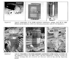
- Figure 2.1 shows the module prior to an explosion test.
- the locations and measurement positions within the module are described using an x-y-z coordinate system with the origin defined as the south-east (front left) corner at lower deck floor level.
- the compass directions are also used to denote positions and boundary locations for the module.
- the front wall plexiglass®
- the inhibitor dispersion system was mounted in the roof of the module, between the centre and south end.
- the floor, roof and back wall of the module were all closed. Explosion venting occurred through the ends of the module for most tests (high confinement). A second venting scenario was also used for a limited number of (reference) tests in which the central section of the front wall was also open (low confinement). These vent areas were covered with thin plastic foil to keep the explosive gas inside the module during gas cloud preparation. The plastic foil was clamped in place using a pneumatic retaining system and was released just prior to ignition to allow it to be easily brushed aside by the ensuing explosion.
- the ignition source was located near the south (left) end of the module in order to maximise flame propagation distance.
- the inhibitor or mitigating agent was added to the container, which was then closed with a "high-pressure bursting disk".
- the container was then charged with nitrogen to 60 bar.
- the location of the dispersion nozzle was the same during all tests.
- the nozzle was mounted in the roof of the module, with the suppressor container outside, on top of the test volume.
- the majority of the inhibitor tests were thus performed by force-triggering the suppression system with a pre-defined delay relative to the moment of ignition. This proved to be the only way of introducing the mitigation/inhibitor agents appropriately into the module given the restraints of the current test set-up.
- the gas-air mixtures were ignited by a powerful oscillating high voltage electric spark.
- the overpressure generated within the test module during the explosion tests was measured using 10 piezo-electric pressure transducers from Kistler (type 7261) connected to Kistler charge amplifiers (type 5007 and 5011).
- the signals from the pressure transducers were measured using the data acquisition system described below.
- the pressure transducers were mounted using five in the roof (P1, P3, P5, P7 & P9) and five in the back wall close to the lower deck (P2, P4, P6, P8 & P10).
- the coordinates of the pressure transducers are given in Table 2.2.
Landscapes
- Health & Medical Sciences (AREA)
- Public Health (AREA)
- Business, Economics & Management (AREA)
- Emergency Management (AREA)
- Chemical Kinetics & Catalysis (AREA)
- Engineering & Computer Science (AREA)
- Chemical & Material Sciences (AREA)
- General Chemical & Material Sciences (AREA)
- Oil, Petroleum & Natural Gas (AREA)
- Feeding, Discharge, Calcimining, Fusing, And Gas-Generation Devices (AREA)
- Emergency Lowering Means (AREA)
- Investigating Or Analyzing Materials Using Thermal Means (AREA)
- Fire-Extinguishing Compositions (AREA)
- Organic Low-Molecular-Weight Compounds And Preparation Thereof (AREA)
- Filling Or Discharging Of Gas Storage Vessels (AREA)
Abstract
The present invention concerns a method to mitigate the consequences of an unconfined or partially confined vapor cloud explosion due to the accidental release of a flammable gas in an open area, wherein :
• means capable to release a flame acceleration suppression product are dispersed in said area,
• a signal is generated by a detector of said flammable gas release, by an operator, by an approaching flame or by the explosion itself,
• said signal activates the release of the flame acceleration suppression product in said area and in a sufficient amount to transform the flammable cloud into a mixture of flammable product, air and said flame acceleration suppression product to prevent important flame accelerations in an unconfined vapor cloud explosion but to let the flammable product burn in case of ignition.
• means capable to release a flame acceleration suppression product are dispersed in said area,
• a signal is generated by a detector of said flammable gas release, by an operator, by an approaching flame or by the explosion itself,
• said signal activates the release of the flame acceleration suppression product in said area and in a sufficient amount to transform the flammable cloud into a mixture of flammable product, air and said flame acceleration suppression product to prevent important flame accelerations in an unconfined vapor cloud explosion but to let the flammable product burn in case of ignition.
In a specific embodiment the release of the flame acceleration suppression product is made by a signal generated by a detector of said flammable gas release or by an operator and before ignition or beginning of an explosion.
Description
- The present invention is a method to mitigate the consequences of an unconfined or partially confined vapor cloud explosion. A particular hazard for petrochemical plants and refineries is an accidental release of a large quantity of flammable material resulting in the formation of a flammable cloud within the installation. Historical evidence has shown that the ignition of such a cloud can lead to a devastating explosion and a total destruction of the installation. Such accidents are commonly named "Vapor Cloud Explosions" (VCE) or "unconfined vapor cloud explosion" and referred as "VCE".
-
US 7153446 provides a fire or explosion suppression agent, having two suppressant parts, one comprising an explosion suppressing chemical substance which is substantially liquid at normal temperatures and pressures and the other comprising a fire or explosion suppressing inert gas; the chemical substance being dispersed as a suspension in the inert gas, the chemical substance when so disposed having low environmental impact, with a short atmospheric lifetime of less than 30 days; the chemical substance comprising one or more specific halogenated chemicals. It is not clear wether the fire or explosion suppression agent is released before or after the fire is initiated. The description mentions only the protection of a specified space or volume such as the interior of a vehicle or a volume within an aircraft. -
EP 562756 -
US 7090028 discloses a method and apparatus for producing an extremely fine micron and sub-micron size water mist using an electronic ultrasonic device that produces the mist at ambient-pressure and delivering the mist for application in suppressing fire. From column 6 lines 50+ it is understood that the mist delivery is made after the beginning of the fire. -
WO 99-24120 -
WO 98-47572 -
US 2003-0000951 provides a method for reducing the severity of vapor cloud explosions in partially confined operating areas, comprising placing porous, high surface-area-to-volume ratio protective material in the area in sufficient amount to reduce the pressure effects caused by ignition of the flammable vapor clouds. According to a preferred embodiment the protective material is a metal mesh or foil material. Examples relate to prevent explosion of a drum containing pentane. The protective material is an expanded aluminum foil, 20 to 80 µm in thickness, of density 30 to 50 kg/m3 and low volumetric displacement (1 to 2%). Said expanded aluminum foil arranged in rolls is inserted in the drum. -
US 5495893 discloses a deflagration suppression system, which is particularly applicable to deflagrations involving combustible gases. The deflagration suppressant in the system is typically water which is dispersed in the combustible gas as a stream of droplets having a Sauter mean Diameter of no more than about 80 microns. The system can include a combustible substance detector to detect potentially explosive concentrations of a combustible substance, such as the combustible gas, before the onset of a deflagration. By detecting the concentration of a combustible substance in a defined region, the sensing means are able to detect a condition in the defined region that is conducive to the occurrence of a deflagration before a deflagration actually occurs. The dispersing means are thus able to disperse a stream of liquid droplets in the defined region before the occurrence of a deflagration and thereby reduce the likelihood of a deflagration occurring in the defined region. - All these above prior arts don't relate to unconfined vapor cloud explosions.
-
US 5096679 relates to a system to mitigate the effect of an environmental release of a contaminant gas. More particularly, it relates to a system to control the spread of a contaminant gas cloud released into the environment. Specifically, it relates to a system to diffuse and/or neutralize the contaminant gas cloud rendering it less hazardous to the surrounding environment. To elaborate on this aspect, said prior art relates to a system having a plurality of fluid effect devices capable of diffusing, diluting and diverting a cloud of contaminant gas; and further capable of chemically altering the contaminant gas to render it environmentally safe. A method for mitigating the effect of the contaminant gas release also is provided. This prior art is mainly concerned with release of chemicals such as hydrogen fluoride. It mentions introduction of calcium carbonate into a cloud of hydrogen fluoride that in this manner will cause a chemical reaction, thus forming calcium fluoride, a non-toxic mineral precipitate easily absorbable by the ground environment. - This prior art relates to the release of a non flammable contaminant in the environment but is silent on the method to mitigate the consequences of an unconfined or partially confined vapor cloud explosion.
- All the prior art is dealing with flame extinguisher or suppression to prevent explosions. The devastating potential of a VCE comes from the acceleration of the flame through the unburnt cloud. The higher the flame speed the higher the overpressure. Under certain circumstances the deflagration can undergo a DDT (Deflagration to Detonation Transition). The current invention consists of introducing a product (or mixture) in the cloud that will avoid acceleration of the flame. This is not a flame extinguisher nor a flame suppression. The result is that the flammable cloud is transformed into a mixture of flammable product, air and flame acceleration suppression product. In case of ignition the maximum potential effect is reduced from a VCE into a "bad" burning flash fire. It means that in case of ignition the flammable gas burns without explosion. An advantage is that the flammable gas has disappeared. The present invention concerns the release of flammable material in open air.
- The present invention concerns a method to mitigate the consequences of an unconfined or partially confined vapor cloud explosion due to the accidental release of a flammable gas in an open area, wherein :
- means capable to release a flame acceleration suppression product are dispersed in said area,
- a signal is generated by a detector of said flammable gas release, by an operator, by an approaching flame or by the explosion itself,
- said signal activates the release of the flame acceleration suppression product in said area and in a sufficient amount to transform the flammable cloud into a mixture of flammable product, air and said flame acceleration suppression product to prevent important flame accelerations in an unconfined vapor cloud explosion but to let the flammable product burn in case of ignition.
- In a specific embodiment the present invention concerns a method to mitigate the consequences of an (unconfined or partially confined) vapor cloud explosion, due to the accidental release of a flammable gas in an area wherein:
- one or more vessels containing a flame acceleration suppression product are dispersed in said area,
- said vessels comprise one or more openings closed with rupture disks and means to rise sharply the pressure inside said vessels,
- a signal is generated by a detector of said flammable gas release, by an operator, by an approaching flame or by the explosion itself,
- said signal activates the means to rise sharply the pressure inside the vessels so as to have the bursting of the rupture disks and the flame acceleration suppression product dispersed in said area and in a sufficient amount to transform the flammable cloud into a mixture of flammable product, air and said flame acceleration suppression product to prevent important flame accelerations in an unconfined vapor cloud explosion but to let the flammable product burn in case of ignition.
- In a specific embodiment the release of the flame acceleration suppression product is made by a signal generated by a detector of said flammable gas release or by an operator and before ignition or beginning of an explosion.
- Flammable gases are handled in many industrial applications, including utilities, chemical and petrochemical manufacturing plants, petroleum refineries, metallurgical industries, distilleries, paint and varnish manufacturing, marine operations, printing, semiconductor manufacturing, pharmaceutical manufacturing, and aerosol can filling operations, as a raw material, product or byproduct. In addition, combustible gases are released by leakage from above-or below-ground piping systems or spillage of flammable liquids. The invention is of high interest for the refineries and petrochemical plants.
- A flammable gas is any gas or vapor that can deflagrate in response to an ignition source when the flammable gas is present in sufficient concentrations by volume with oxygen. Deflagration is typically caused by the negative heat of formation of the flammable gas. Flammable gases generally deflagrate at concentrations above the lower explosive limit and below the upper explosive limit of the flammable gas. In a deflagration, the combustion of a flammable gas, or other flammable substance, initiates a chemical reaction that propagates outwards by transferring heat and/or free radicals to adjacent molecules of the flammable gas. A free radical is any reactive group of atoms containing unpaired electrons, such as OH, H, CH3, R•, ROO• et al. The transfer of heat and/or free radicals ignites the adjacent molecules. In this manner, the deflagration propagates or expands outward through the flammable gas generally at subsonic velocities in the unburnt gas. The heat generated by the deflagration generally causes a rapid pressure increase in confined areas. The combustion is a chain reaction that consist in four steps: initiation, propagation, branching and termination. During these 4 steps various radicals are formed such as R•, ROO•, H•, OH•, ... The branching step is very important as it determines the explosive character of the combustion.
- After release, the flame acceleration suppression product not only dilutes the oxygen available for the combustion of the flammable gas but also impairs the ability of free radicals to propagate the deflagration. The dilution of the oxygen decreases the concentration of the oxygen available to react with the flammable gas and thereby slows the propagation rate of the deflagration. The flame acceleration suppression product impairs the ability of free radicals to propagate the deflagration by reacting with the free radicals released in the combustion reaction before the free radicals can react with combustible gas molecules adjacent to the deflagration.
- While the method of the invention can be employed to suppress deflagrations associated with flammable gases, the method is particularly applicable to suppressing deflagrations of flammable gases having combustion temperatures ranging from about 500°C to about 2500°C. Such flammable gases include benzene, ether, methane, ethane, hydrogen, butane, propane, carbon monoxide, heptane, formaldehyde, acetylene, ethylene, hydrazine, acetone, carbon disulfide, ethyl acetate, hexane, methyl alcohol, methyl ethyl ketone, octane, pentane, toluene, xylene, and mixtures thereof.
- The flame acceleration suppression product is any product which captures the free radicals and as such limits the branching reactions. The result is that the flame acceleration is altered and that a devastating explosion is mitigated. The flammable gas will burn more slowely and not develop in a devastating explosion in case of an ignition. The flame acceleration suppression product should not create an important risk (e.g. toxic) for humans or the environment. The acceleration suppression product can be a gas, a liquid or a solid (advantageously in a powder form and preferably in a dry powder form). Advantageously the acceleration suppression product is dispersed in the area by a carrier gas originally contained in the vessel. The flame acceleration suppression product is advantageously a metal compound such as, by way of example, a salt. Several products (salts) and mixtures have been tested. The aim of the flame acceleration suppression mixture is to allow capture of different type of radicals. Some compounds in the mixture capture H• (hydrogen radicals) or OH• (hydroxyl radicals) radicals while other capture for instance R• (alkyl radicals), RO• (alkoxy radicals) or ROO• (peroxy radicals). Some of the compounds release CO2 while bounding with radical and this gives an additional dilution effect. Experiments have been performed at SOTRA (Norway) by an independent organisation in a 50 m3 module (8 m x 2,5 m x 2,5 m). Pressure reduction up to 50% have been obtained so far. Additional tests are ongoing to improve the effectiveness but it was demonstrated that the mechanism works. The man skilled in the art can easily, by routine experiments, select convenient flame acceleration suppression products. It would not depart from the scope of the invention to use a mixture of two or more flame acceleration suppression products. The quantities to be used can vary in a wide range and can be from 50 gr/m3 to 500 gr/m3 advantageously from 200 to 400 gr/m3.
- By way of example of flame acceleration suppression products, one can cite sodium bicarbonate (NaHCO3), potassium bicarbonate (KHCO3), sodium chloride and sodium carbonate. The flame acceleration suppression product can be mixed with primary anti-oxidants (ROO• and RO• capture) and/or secondary antioxidants (R• capture).
- The vessels containing the flame acceleration suppression product are dispersed in the area to be protected. Number of vessels, location of each vessel, amount of the flame acceleration suppression product in each vessel are linked to speed of dispersion of the flame acceleration suppression product in the flammable gas vapor cloud and the amount of flame acceleration suppression product to be dispersed in the flammable gas vapor cloud.
- About the means to rise sharply the pressure inside said vessels it can be a CO2 cartridge or an explosive like the airbag system in the cars. Said CO2 or the gases generated by the explosives can be the carrier gas. Said means are known per se.
- About the signal to activate the means to rise sharply the pressure inside the vessels this signal and said means are known per se.
- Important factors for success for the method are:
- Right time for activation;
- Reliability of the system;
- Coverage;
- Persistence;
- Safety for the people
- Explosion mitigation capability flame acceleration suppression product (FASP).
- Ideally the activation has to be done at the most optimum instant that is: After a certain time in order to give people the possibility to evacuate the unit; A certain time after the occurrence of the leak to enable the flammable cloud to be formed;
Long enough before the moment of ignition to ensure that mixing can take place. - The flame acceleration suppression product has to remain airborne in the cloud as long as the risk of a VCE is possible.
- In the following examples the flame acceleration suppression product is designated as inhibitor or mitigating agent.
- The experiments were performed in an explosion test module. The module is 8.0 m long, 2.5 m high and 2.5 m wide, thus having a volume of 50.0 m3. The module has a coarse steel grating forming a mezzanine deck 1.25 m above the floor of the vessel. Some of the standard objects (obstructions) inside the module were removed in order to produce the desired explosion loading scenario for the tests.
Figure 2.1 shows the module prior to an explosion test. - The locations and measurement positions within the module are described using an x-y-z coordinate system with the origin defined as the south-east (front left) corner at lower deck floor level. The compass directions are also used to denote positions and boundary locations for the module. The front wall (plexiglass®) is facing east and the inhibitor dispersion system was mounted in the roof of the module, between the centre and south end.
- The floor, roof and back wall of the module were all closed. Explosion venting occurred through the ends of the module for most tests (high confinement). A second venting scenario was also used for a limited number of (reference) tests in which the central section of the front wall was also open (low confinement). These vent areas were covered with thin plastic foil to keep the explosive gas inside the module during gas cloud preparation. The plastic foil was clamped in place using a pneumatic retaining system and was released just prior to ignition to allow it to be easily brushed aside by the ensuing explosion.
- The ignition source was located near the south (left) end of the module in order to maximise flame propagation distance.
- In order to introduce the flame inhibitors and/or other explosion mitigation agents into the module, an explosion suppression system was used. This system was provided by Kidde Brand- und Explosionsshutz GmbH, Germany, and the typical parts of this system are shown in
Figure 2.2. Figure 2.3 shows the suppressor container and the telescopic dispersion nozzle used during the tests as it was installed and used in the experiments. - The inhibitor or mitigating agent was added to the container, which was then closed with a "high-pressure bursting disk". The container was then charged with nitrogen to 60 bar. Finally a "powder pack capsule" and gasket, with integral detonating cord and detonator, was fitted over the bursting disk and the entire system mounted onto the 5" flange on the roof of the module as indicated in
Figure 2.3 . - The location of the dispersion nozzle was the same during all tests. The nozzle was mounted in the roof of the module, with the suppressor container outside, on top of the test volume. The location coordinates of the centre of the nozzle inlet was x = 3.25 m, y = 1.25 m.
- The pressure sensor was mounted in the back wall of the upper deck, at x = 2.25 m, y=2.50 m, z=2.10 m) The majority of the inhibitor tests were thus performed by force-triggering the suppression system with a pre-defined delay relative to the moment of ignition. This proved to be the only way of introducing the mitigation/inhibitor agents appropriately into the module given the restraints of the current test set-up.
- Despite the satisfactory reproducibility and timing accuracy of the test control and switching system, small variations were observed between the time of activation of the ignition unit and the actual time of occurrence of the ignition spark. This was found to vary within the order of ±10 ms. The actual time of activation and firing of the inhibitor dispersion system thus had to be obtained from the measured data and quoted as an activation delay with respect to the time of the spark.
- Although the main aim of the current work was to test the mitigation properties of flame inhibitors, a number of tests were performed with pure water (without inhibitor salts) to provide a reference with waterspray. Two tests were performed using pressurised water only in the suppressor container. Also since the mitigating agent dispersion was from a pressured container, driven by nitrogen at a starting pressure of 60 barg, another reference condition was tested using nitrogen only, without water or inhibitor salts. Two tests were performed using nitrogen only.
- In total, three different flame inhibitor compounds were tested during the current work. These were all tested as solids and one of them (potassium bicarbonate) was also tested in solution with water at several different concentrations. The main physical properties, in terms of moisture content and particle size distribution, for these inhibitor compounds are given in Table 2.1.

- The experiments were performed with explosive gas mixtures of methane in air and propane in air. The majority of the tests were performed using propane. Near stoichiometric mixtures were used in the tests (methane concentration = approx 9.5 %vol, propane = approx 4.0 %vol). The gas concentration of the mixtures was monitored using an infrared gas analyser (type Uras 10E).
- The gas-air mixtures were ignited by a powerful oscillating high voltage electric spark. The ignition source was located just above the mezzanine deck near the south end of the module (position x = 1.00 m, y = 1.35 m and z = 1.35 m).
- The overpressure generated within the test module during the explosion tests was measured using 10 piezo-electric pressure transducers from Kistler (type 7261) connected to Kistler charge amplifiers (type 5007 and 5011). The signals from the pressure transducers were measured using the data acquisition system described below. The pressure transducers were mounted using five in the roof (P1, P3, P5, P7 & P9) and five in the back wall close to the lower deck (P2, P4, P6, P8 & P10). The coordinates of the pressure transducers are given in Table 2.2.
- Purpose-built test control and data acquisition application programmes, based on multipurpose data acquisition card (PCI-6071) and relay switching cards from National Instruments together with the LabView programming platform were used to perform the experiments.
- All tests were recorded using standard SVHS and digital video cameras (Panasonic SVHS and Sony DV camera). A majority of the tests were also recorded using a high-speed digital SLR camera (Casio).

- The time at which the suppression/dispersion system was activated was varied since this proved to be a factor governing the mitigation behaviour of the inhibitor agents.
A total of 29 tests were performed in the current work. A breakdown of the tests is as follows: - 3 tests in the low congestion, low confinement module configuration (all reference tests, no tests with inhibitors).
- 26 tests in the low congestion, high confinement module configuration (8 reference tests, 18 tests with inhibitors/mitigating agents).
- 2 tests with methane, 27 tests with propane.
- Of the 18 inhibitor tests, 2 were performed using nitrogen only, 2 with water only, 2 with potassium bicarbonate in aqueous solution and 12 tests were performed with dry inhibitor salts only (without water).
- Of the 12 tests with dry inhibitor salts, 1 test was performed with sodium chloride, 2 tests were performed using sodium bicarbonate and 9 tests were performed with potassium bicarbonate.
- The following tables give a summary of the measured test results. Peak explosion pressures are given in Table 4.1 while the time of occurrence of the peak pressure relative to the moment of the ignition spark is given in Table 4.2. In said tables tests are referred as shot number.


- The above tables 4.1 and 4.2 show clearly that the peak explosion pressure and the arrival of peak explosion pressure are highly reduced when the flame acceleration suppression product is introduced in the flammable gas.
tests 8, 12 are made with propane and water as inhibitor,
tests 9, 24, 10, 13, 20, 14, 17, 18, 22-23, 25 are made with propane and KHC03 as inhibitor,
test 26 is made propane and NaCl as ihhibitor,
tests 28-29 are made with propane and Na2CO3 as inhibitor,
tests 11, 19, 1-2 are made and no inhibitor,
tests 3-4 are made with methane and no inhibitor.
Claims (3)
- Method to mitigate the consequences of an unconfined or partially confined vapor cloud explosion due to the accidental release of a flammable gas in an open area, wherein :• means capable to release a flame acceleration suppression product are dispersed in said area,• a signal is generated by a detector of said flammable gas release, by an operator, by an approaching flame or by the explosion itself,• said signal activates the release of the flame acceleration suppression product in said area and in a sufficient amount to transform the flammable cloud into a mixture of flammable product, air and said flame acceleration suppression product to prevent important flame accelerations in an unconfined vapor cloud explosion but to let the flammable product burn in case of ignition.
- Method according to claim 1 wherein the means capable to release a flame acceleration suppression product are one or more vessels containing a flame acceleration suppression product dispersed in said area, said vessels comprising one or more openings closed with rupture disks and means to rise sharply the pressure inside said vessels,
the signal generated by a detector of said flammable gas release, by an operator, by an approaching flame or by the explosion itself, activates the means to rise sharply the pressure inside said vessels so as to have the bursting of the rupture disks and the flame acceleration suppression product dispersed in said area. - Method according to claim 1 or 2 wherein the release of the flame acceleration suppression product is made by a signal generated by a detector of said flammable gas release or by an operator and is made before ignition or beginning of an explosion.
Priority Applications (14)
| Application Number | Priority Date | Filing Date | Title |
|---|---|---|---|
| EP08160954A EP2153872A1 (en) | 2008-07-23 | 2008-07-23 | Method to mitigate the consequences of an unconfined or partially confined vapor cloud explosion |
| PT98000367T PT2303412T (en) | 2008-07-23 | 2009-07-16 | Method to mitigate the consequences of an unconfined vapor cloud explosion |
| HRP20170425TT HRP20170425T1 (en) | 2008-07-23 | 2009-07-16 | Method to mitigate the consequences of an unconfined vapor cloud explosion |
| EP09800036.7A EP2303412B1 (en) | 2008-07-23 | 2009-07-16 | Method to mitigate the consequences of an unconfined vapor cloud explosion |
| ES09800036.7T ES2620005T3 (en) | 2008-07-23 | 2009-07-16 | Procedure to mitigate the consequences of a steam cloud explosion without confining |
| LTEP09800036.7T LT2303412T (en) | 2008-07-23 | 2009-07-16 | Method to mitigate the consequences of an unconfined vapor cloud explosion |
| CN200980128767XA CN102105196B (en) | 2008-07-23 | 2009-07-16 | Method to mitigate consequences of unconfined or partially confined vapor cloud explosion |
| US13/054,982 US10300316B2 (en) | 2008-07-23 | 2009-07-16 | Method to mitigate the consequences of an unconfined or partially confined vapor cloud explosion |
| DK09800036.7T DK2303412T3 (en) | 2008-07-23 | 2009-07-16 | PROCEDURE FOR REDUCING THE CONSEQUENCES OF AN UNLIMITED VAPOR VIEW POSITION |
| PCT/EP2009/059190 WO2010010044A1 (en) | 2008-07-23 | 2009-07-16 | Method to mitigate the consequences of an unconfined or partially confined vapor cloud explosion |
| HUE09800036A HUE032414T2 (en) | 2008-07-23 | 2009-07-16 | Method to mitigate the consequences of an unconfined vapor cloud explosion |
| SI200931633A SI2303412T1 (en) | 2008-07-23 | 2009-07-16 | Method to mitigate the consequences of an unconfined vapor cloud explosion |
| KR1020117001642A KR101353300B1 (en) | 2008-07-23 | 2009-07-16 | Method to mitigate the consequences of an unconfined or partially confined vapor cloud explosion |
| PL09800036T PL2303412T3 (en) | 2008-07-23 | 2009-07-16 | Method to mitigate the consequences of an unconfined vapor cloud explosion |
Applications Claiming Priority (1)
| Application Number | Priority Date | Filing Date | Title |
|---|---|---|---|
| EP08160954A EP2153872A1 (en) | 2008-07-23 | 2008-07-23 | Method to mitigate the consequences of an unconfined or partially confined vapor cloud explosion |
Publications (1)
| Publication Number | Publication Date |
|---|---|
| EP2153872A1 true EP2153872A1 (en) | 2010-02-17 |
Family
ID=40276082
Family Applications (2)
| Application Number | Title | Priority Date | Filing Date |
|---|---|---|---|
| EP08160954A Withdrawn EP2153872A1 (en) | 2008-07-23 | 2008-07-23 | Method to mitigate the consequences of an unconfined or partially confined vapor cloud explosion |
| EP09800036.7A Not-in-force EP2303412B1 (en) | 2008-07-23 | 2009-07-16 | Method to mitigate the consequences of an unconfined vapor cloud explosion |
Family Applications After (1)
| Application Number | Title | Priority Date | Filing Date |
|---|---|---|---|
| EP09800036.7A Not-in-force EP2303412B1 (en) | 2008-07-23 | 2009-07-16 | Method to mitigate the consequences of an unconfined vapor cloud explosion |
Country Status (13)
| Country | Link |
|---|---|
| US (1) | US10300316B2 (en) |
| EP (2) | EP2153872A1 (en) |
| KR (1) | KR101353300B1 (en) |
| CN (1) | CN102105196B (en) |
| DK (1) | DK2303412T3 (en) |
| ES (1) | ES2620005T3 (en) |
| HR (1) | HRP20170425T1 (en) |
| HU (1) | HUE032414T2 (en) |
| LT (1) | LT2303412T (en) |
| PL (1) | PL2303412T3 (en) |
| PT (1) | PT2303412T (en) |
| SI (1) | SI2303412T1 (en) |
| WO (1) | WO2010010044A1 (en) |
Cited By (1)
| Publication number | Priority date | Publication date | Assignee | Title |
|---|---|---|---|---|
| EP2732852A1 (en) * | 2012-11-14 | 2014-05-21 | Total Raffinage Marketing | Mitigation of vapor cloud explosion by chemical inhibition |
Families Citing this family (6)
| Publication number | Priority date | Publication date | Assignee | Title |
|---|---|---|---|---|
| EP2866903B1 (en) * | 2012-07-02 | 2016-08-24 | Basf Se | Method for diluting and/or flushing out clouds of combustible gases |
| CN103558863B (en) * | 2013-10-23 | 2015-12-30 | 中盐安徽红四方股份有限公司 | A kind of sodium hydrosulfite four-in-one kettle blow-out disc secure side is to localization method |
| CN105457209B (en) * | 2015-12-21 | 2018-06-05 | 徐州中矿消防安全技术装备有限公司 | A kind of fire-fighting pin device for handling dangerous material |
| CN108499506B (en) * | 2018-04-14 | 2020-09-25 | 同济大学 | A kind of explosion-proof atmospheric pressure reactor and its realization method |
| CN113673109B (en) * | 2021-08-24 | 2025-03-11 | 中国石油大学(华东) | A gas cloud explosion assessment method and system for coupling multiple potential gas explosion sources |
| CN114738039B (en) * | 2022-04-19 | 2023-06-23 | 常州大学 | A preparation method of polydopamine-coated mixed powder modified explosion suppression material |
Citations (10)
| Publication number | Priority date | Publication date | Assignee | Title |
|---|---|---|---|---|
| DE1127812B (en) * | 1955-12-27 | 1962-04-12 | Graviner Manufacturing Co | Method for suppressing an explosion of a flammable fuel-vapor-air mixture |
| GB2029215A (en) * | 1978-08-30 | 1980-03-19 | Field Hazaard Co Ltd | Prevention of explosions |
| US5096679A (en) | 1988-04-01 | 1992-03-17 | The Standard Oil Company | System to mitigate the effect of an environmental release of a contaminant gas |
| EP0562756A1 (en) | 1992-03-21 | 1993-09-29 | Kidde-Graviner Limited | Fire extinguishing and explosion suppression substances |
| US5495893A (en) | 1994-05-10 | 1996-03-05 | Ada Technologies, Inc. | Apparatus and method to control deflagration of gases |
| WO1998047572A1 (en) | 1997-04-24 | 1998-10-29 | Kidde Fire Protection Limited | Explosion suppression arrangements and methods |
| WO1999024120A1 (en) | 1997-11-12 | 1999-05-20 | Kidde-Graviner Limited | Fire or explosion suppressants and methods |
| US20030000951A1 (en) | 2001-05-21 | 2003-01-02 | Clark David G. | Method for reducing the severity of vapor cloud explosions |
| US7090028B2 (en) | 2001-09-19 | 2006-08-15 | Nanomist Systems, Llc | Fire suppression using water mist with ultrafine size droplets |
| US7153446B2 (en) | 2001-03-29 | 2006-12-26 | Kidde Ip Holdings Limited | Fire and explosion suppression |
Family Cites Families (8)
| Publication number | Priority date | Publication date | Assignee | Title |
|---|---|---|---|---|
| US2029215A (en) * | 1934-09-14 | 1936-01-28 | Harry N Atwood | Cellular construction for aircraft pontoons |
| US2869647A (en) * | 1953-04-09 | 1959-01-20 | Graviner Manufacturing Co | Means for detecting and suppressing explosions |
| US3482637A (en) * | 1967-10-20 | 1969-12-09 | Us Interior | Process and method for quenching incipient gas-air explosions |
| GB2042866B (en) * | 1979-02-02 | 1983-04-13 | Pennwalt Corp | Process for reducing grain dust explosibility |
| US5119877A (en) * | 1990-07-19 | 1992-06-09 | The United States Of America As Represented By The Secretary Of The Interior | Explosion suppression system |
| WO1994019060A1 (en) | 1993-02-16 | 1994-09-01 | Spectronix Ltd. | Fire extinguishing methods and systems |
| CN1049052C (en) * | 1995-07-07 | 2000-02-02 | 中国石化洛阳石油化工总厂 | Intelligent oil refining chemical hazard source accident plan and emergency treatment method |
| RU2158150C1 (en) * | 1999-11-22 | 2000-10-27 | ГУП Научно-исследовательский институт полимерных материалов | Fire localizing and extinguishing method |
-
2008
- 2008-07-23 EP EP08160954A patent/EP2153872A1/en not_active Withdrawn
-
2009
- 2009-07-16 HR HRP20170425TT patent/HRP20170425T1/en unknown
- 2009-07-16 EP EP09800036.7A patent/EP2303412B1/en not_active Not-in-force
- 2009-07-16 SI SI200931633A patent/SI2303412T1/en unknown
- 2009-07-16 LT LTEP09800036.7T patent/LT2303412T/en unknown
- 2009-07-16 PL PL09800036T patent/PL2303412T3/en unknown
- 2009-07-16 WO PCT/EP2009/059190 patent/WO2010010044A1/en not_active Ceased
- 2009-07-16 ES ES09800036.7T patent/ES2620005T3/en active Active
- 2009-07-16 PT PT98000367T patent/PT2303412T/en unknown
- 2009-07-16 KR KR1020117001642A patent/KR101353300B1/en active Active
- 2009-07-16 CN CN200980128767XA patent/CN102105196B/en not_active Expired - Fee Related
- 2009-07-16 HU HUE09800036A patent/HUE032414T2/en unknown
- 2009-07-16 DK DK09800036.7T patent/DK2303412T3/en active
- 2009-07-16 US US13/054,982 patent/US10300316B2/en active Active
Patent Citations (10)
| Publication number | Priority date | Publication date | Assignee | Title |
|---|---|---|---|---|
| DE1127812B (en) * | 1955-12-27 | 1962-04-12 | Graviner Manufacturing Co | Method for suppressing an explosion of a flammable fuel-vapor-air mixture |
| GB2029215A (en) * | 1978-08-30 | 1980-03-19 | Field Hazaard Co Ltd | Prevention of explosions |
| US5096679A (en) | 1988-04-01 | 1992-03-17 | The Standard Oil Company | System to mitigate the effect of an environmental release of a contaminant gas |
| EP0562756A1 (en) | 1992-03-21 | 1993-09-29 | Kidde-Graviner Limited | Fire extinguishing and explosion suppression substances |
| US5495893A (en) | 1994-05-10 | 1996-03-05 | Ada Technologies, Inc. | Apparatus and method to control deflagration of gases |
| WO1998047572A1 (en) | 1997-04-24 | 1998-10-29 | Kidde Fire Protection Limited | Explosion suppression arrangements and methods |
| WO1999024120A1 (en) | 1997-11-12 | 1999-05-20 | Kidde-Graviner Limited | Fire or explosion suppressants and methods |
| US7153446B2 (en) | 2001-03-29 | 2006-12-26 | Kidde Ip Holdings Limited | Fire and explosion suppression |
| US20030000951A1 (en) | 2001-05-21 | 2003-01-02 | Clark David G. | Method for reducing the severity of vapor cloud explosions |
| US7090028B2 (en) | 2001-09-19 | 2006-08-15 | Nanomist Systems, Llc | Fire suppression using water mist with ultrafine size droplets |
Cited By (3)
| Publication number | Priority date | Publication date | Assignee | Title |
|---|---|---|---|---|
| EP2732852A1 (en) * | 2012-11-14 | 2014-05-21 | Total Raffinage Marketing | Mitigation of vapor cloud explosion by chemical inhibition |
| WO2014076097A3 (en) * | 2012-11-14 | 2014-07-03 | Total Raffinage Chimie | Mitigation of vapor cloud explosion by chemical inhibition |
| US10220230B2 (en) | 2012-11-14 | 2019-03-05 | Total Raffinage Chimie | Mitigation of vapor cloud explosion by chemical inhibition |
Also Published As
| Publication number | Publication date |
|---|---|
| ES2620005T3 (en) | 2017-06-27 |
| US20170225020A1 (en) | 2017-08-10 |
| SI2303412T1 (en) | 2017-04-26 |
| HRP20170425T1 (en) | 2017-06-16 |
| WO2010010044A1 (en) | 2010-01-28 |
| CN102105196B (en) | 2013-10-23 |
| PT2303412T (en) | 2017-03-15 |
| KR20110028630A (en) | 2011-03-21 |
| CN102105196A (en) | 2011-06-22 |
| HUE032414T2 (en) | 2017-09-28 |
| US10300316B2 (en) | 2019-05-28 |
| PL2303412T3 (en) | 2017-07-31 |
| EP2303412A1 (en) | 2011-04-06 |
| EP2303412B1 (en) | 2017-01-04 |
| KR101353300B1 (en) | 2014-01-20 |
| DK2303412T3 (en) | 2017-04-24 |
| LT2303412T (en) | 2017-04-25 |
Similar Documents
| Publication | Publication Date | Title |
|---|---|---|
| EP2303412B1 (en) | Method to mitigate the consequences of an unconfined vapor cloud explosion | |
| RU2595990C2 (en) | Methods and device for multistage fire extinguishing system | |
| US5425426A (en) | Fire extinguishing methods and systems | |
| US12427352B2 (en) | Aerosol fire suppression materials, systems and methods of implementation | |
| KR102728339B1 (en) | Gas hydrate fire bomb and flame suppression method using same | |
| JPH10500041A (en) | Apparatus and method for suppressing gas deflagration | |
| CA2643525A1 (en) | Vehicle fire extinguisher | |
| US2693240A (en) | Method and apparatus for preventing explosions and extinguishing fires | |
| EP2919865B1 (en) | Mitigation of vapor cloud explosion by chemical inhibition | |
| CN101940825B (en) | A Method for Suppressing Oil and Gas Explosions in Confined Spaces | |
| JP5694347B2 (en) | Method and apparatus for a two-stage risk control system | |
| US20220126147A1 (en) | Device and method of anti-inflammation capsule | |
| RU2633955C1 (en) | Device of automatic local fire protection and method of destruction of shell of capsule with nanopowder | |
| Moore | Suppression of maize dust explosions | |
| Zbigniew et al. | Active protection of work area against explosion of dust–gas mixture | |
| EP2155408B1 (en) | Method for restraining a chemical discharge | |
| Kim et al. | Explosion suppression of an armoured vehicle crew compartment | |
| Bennett | Review of technologies for active suppression for fuel tank explosions | |
| Senecal et al. | Explosion Suppression in Occupied Spaces | |
| Kim et al. | Water Mist System for Explosion Protection of an Armored Vehicle Crew Compartment | |
| Strehlow | Accidental Explosions: Recent research has significantly increased our understanding of the causes and behavior of accidental explosions and has produced new and more effective safety measures | |
| Zeeuwen | Technical Manager-Process Safety Consultancy Chilworth Technology Limited | |
| Cross et al. | Dust Explosion Protection | |
| GB2535694A (en) | Safety device |
Legal Events
| Date | Code | Title | Description |
|---|---|---|---|
| PUAI | Public reference made under article 153(3) epc to a published international application that has entered the european phase |
Free format text: ORIGINAL CODE: 0009012 |
|
| AK | Designated contracting states |
Kind code of ref document: A1 Designated state(s): AT BE BG CH CY CZ DE DK EE ES FI FR GB GR HR HU IE IS IT LI LT LU LV MC MT NL NO PL PT RO SE SI SK TR |
|
| AX | Request for extension of the european patent |
Extension state: AL BA MK RS |
|
| AKY | No designation fees paid | ||
| REG | Reference to a national code |
Ref country code: DE Ref legal event code: 8566 |
|
| STAA | Information on the status of an ep patent application or granted ep patent |
Free format text: STATUS: THE APPLICATION IS DEEMED TO BE WITHDRAWN |
|
| 18D | Application deemed to be withdrawn |
Effective date: 20100818 |