EP2153619B1 - Method for pairing and authenticating one or more medical devices and one or more remote electronic devices - Google Patents
Method for pairing and authenticating one or more medical devices and one or more remote electronic devices Download PDFInfo
- Publication number
- EP2153619B1 EP2153619B1 EP08770444.1A EP08770444A EP2153619B1 EP 2153619 B1 EP2153619 B1 EP 2153619B1 EP 08770444 A EP08770444 A EP 08770444A EP 2153619 B1 EP2153619 B1 EP 2153619B1
- Authority
- EP
- European Patent Office
- Prior art keywords
- remote electronic
- electronic device
- medical device
- pin code
- medical
- Prior art date
- Legal status (The legal status is an assumption and is not a legal conclusion. Google has not performed a legal analysis and makes no representation as to the accuracy of the status listed.)
- Active
Links
Images


Classifications
-
- H—ELECTRICITY
- H04—ELECTRIC COMMUNICATION TECHNIQUE
- H04L—TRANSMISSION OF DIGITAL INFORMATION, e.g. TELEGRAPHIC COMMUNICATION
- H04L63/00—Network architectures or network communication protocols for network security
- H04L63/06—Network architectures or network communication protocols for network security for supporting key management in a packet data network
- H04L63/061—Network architectures or network communication protocols for network security for supporting key management in a packet data network for key exchange, e.g. in peer-to-peer networks
-
- G—PHYSICS
- G16—INFORMATION AND COMMUNICATION TECHNOLOGY [ICT] SPECIALLY ADAPTED FOR SPECIFIC APPLICATION FIELDS
- G16H—HEALTHCARE INFORMATICS, i.e. INFORMATION AND COMMUNICATION TECHNOLOGY [ICT] SPECIALLY ADAPTED FOR THE HANDLING OR PROCESSING OF MEDICAL OR HEALTHCARE DATA
- G16H40/00—ICT specially adapted for the management or administration of healthcare resources or facilities; ICT specially adapted for the management or operation of medical equipment or devices
- G16H40/60—ICT specially adapted for the management or administration of healthcare resources or facilities; ICT specially adapted for the management or operation of medical equipment or devices for the operation of medical equipment or devices
- G16H40/63—ICT specially adapted for the management or administration of healthcare resources or facilities; ICT specially adapted for the management or operation of medical equipment or devices for the operation of medical equipment or devices for local operation
-
- G—PHYSICS
- G16—INFORMATION AND COMMUNICATION TECHNOLOGY [ICT] SPECIALLY ADAPTED FOR SPECIFIC APPLICATION FIELDS
- G16H—HEALTHCARE INFORMATICS, i.e. INFORMATION AND COMMUNICATION TECHNOLOGY [ICT] SPECIALLY ADAPTED FOR THE HANDLING OR PROCESSING OF MEDICAL OR HEALTHCARE DATA
- G16H40/00—ICT specially adapted for the management or administration of healthcare resources or facilities; ICT specially adapted for the management or operation of medical equipment or devices
- G16H40/60—ICT specially adapted for the management or administration of healthcare resources or facilities; ICT specially adapted for the management or operation of medical equipment or devices for the operation of medical equipment or devices
- G16H40/67—ICT specially adapted for the management or administration of healthcare resources or facilities; ICT specially adapted for the management or operation of medical equipment or devices for the operation of medical equipment or devices for remote operation
-
- H—ELECTRICITY
- H04—ELECTRIC COMMUNICATION TECHNIQUE
- H04L—TRANSMISSION OF DIGITAL INFORMATION, e.g. TELEGRAPHIC COMMUNICATION
- H04L63/00—Network architectures or network communication protocols for network security
- H04L63/08—Network architectures or network communication protocols for network security for authentication of entities
- H04L63/0869—Network architectures or network communication protocols for network security for authentication of entities for achieving mutual authentication
-
- H—ELECTRICITY
- H04—ELECTRIC COMMUNICATION TECHNIQUE
- H04W—WIRELESS COMMUNICATION NETWORKS
- H04W12/00—Security arrangements; Authentication; Protecting privacy or anonymity
- H04W12/50—Secure pairing of devices
-
- H—ELECTRICITY
- H04—ELECTRIC COMMUNICATION TECHNIQUE
- H04W—WIRELESS COMMUNICATION NETWORKS
- H04W12/00—Security arrangements; Authentication; Protecting privacy or anonymity
- H04W12/06—Authentication
-
- H—ELECTRICITY
- H04—ELECTRIC COMMUNICATION TECHNIQUE
- H04W—WIRELESS COMMUNICATION NETWORKS
- H04W84/00—Network topologies
- H04W84/18—Self-organising networks, e.g. ad-hoc networks or sensor networks
Definitions
- the present invention relates generally to medical devices configured to wirelessly communicate with remote electronic devices, and more specifically to pairing and authenticating one or more medical devices and one or more remote devices for subsequent secure wireless communications.
- a medical device such as an ambulatory medical device
- a remote electronic device It is desirable with such arrangements to configure the medical device and the remote electronic device in a manner that provides for secure wireless communications between the two devices. It is further desirable in systems that may include a plurality of medical devices and/or a plurality of remote electronic devices to configure one or more of the medical devices and one or more of the remote electronic devices in a manner that provides for secure wireless communications between various combinations of the devices.
- a method for authenticating a medical device and a remote electronic device that are placed in communication range relative to each other may comprise generating at least a portion of a PIN code by one of the medical device and the remote electronic device, capturing the at least a portion of the generated PIN code with the other of the medical device and the remote electronic device, checking authentication of the PIN code, which is based at least in part on the captured at least a portion of the generated PIN code, by the one of the medical device and the remote electronic device, generating at least one strong key by one of the medical device and the remote electronic device, sending the at least one strong key encrypted to the other of the medical device and the remote electronic device, checking authentication of the sent at least one strong key by the one of the medical device and the remote electronic device, and upon successful authentication of the PIN code and the at least one strong key, storing the at least one strong key in a memory of the medical device and in
- generating at least a portion of a PIN code may comprise generating a complete PIN code by the one of the medical device and the remote electronic device. Capturing the at least a portion of the generated PIN code comprises capturing the complete PIN code with the other of the medical device and the remote electronic device. Checking authentication of the PIN code comprises checking authentication of the captured complete PIN code by the one of the medical device and the remote electronic device.
- the method may further comprise generating at least another portion of the PIN code by the other of the medical device and the remote electronic device, and forming by the other of the medical device and the remote electronic device a complete PIN code based on the at least a portion of the PIN code and the at least another portion of the PIN code.
- checking authentication of the PIN code may comprise checking authentication of the complete PIN code by the one of the medical device and the remote electronic device.
- capturing the at least a portion of the generated PIN code may comprise displaying the at least a portion of the generated PIN code by the one of the medical device and the remote electronic device, and instructing via a display of the other of the medical device and the remote electronic device manual input of the at least a portion of the generated PIN code into the other of the medical device and the remote electronic device.
- capturing the at least a portion of the generated PIN code may comprise one of sending the at least a portion of the generated PIN code by the one of the medical device and the remote electronic device to the other of the medical device and the remote electronic device and retrieving the at least a portion of the generated PIN code by the other of the medical device and the remote electronic device from the one of the medical device and the remote electronic device.
- the method may further comprise exchanging respective device identification codes between the medical device and the remote electronic device.
- the respective device identification codes may, for example, be exchanged between the medical device and the remote electronic device following authentication of the at least one strong key.
- the method may return to the step of generating at least a portion of a PIN code by one of the medical device and the remote electronic device.
- a message may be displayed on at least one of the medical device and the remote electronic device indicating that the authentication was not successful and the method may return to the step of displaying the at least a portion of the generated PIN code by the one of the medical device and the remote electronic device, upon non-successful authentication of either of the PIN code and the at least one strong key.
- the method may further comprise restarting the other of the medical device and the remote electronic device upon successful authentication of the PIN code and the at least one strong key.
- the method may further comprise performing a pairing phase prior to executing any of the steps of the method for authenticating.
- the pairing phase may comprise setting the other of the medical device and the remote electronic device in a pairable mode in order to be discoverable by the one of the medical device and the remote electronic device, setting the one of the medical device and the remote electronic device in a pairing mode, performing a device discovery inquiry by the one of the medical device and the remote electronic device, displaying discovered devices resulting from the device discovery inquiry, upon user selection from the displayed discovered devices of the other of the medical device and the remote electronic device, pairing the one of the medical device and the remote electronic device with the other of the medical device and the remote electronic device, upon successful pairing generating a link key on the medical device and on the remote electronic device, storing the link key and a virtual address of the other of the medical device and the remote electronic device in a memory of the one of the medical device and the remote electronic device, and storing the link key and a virtual address of the one of the medical device and the remote electronic device in a pairable mode in order
- BlueTooth® may be used as a communication protocol for communication between the medical device and the remote electronic device during the pairing phase.
- the method may further comprise filtering discovered devices resulting from the device discovery inquiry prior to displaying the discovered devices such that only discovered devices that are in the pairable mode are displayed for user selection.
- the method may further comprise filtering discovered devices resulting from the device discovery inquiry prior to displaying the discovered devices by comparing the discovered devices to entries of a predefined device list and displaying only the discovered devices that match entries on the predefined device list.
- the method may further comprise requesting authentication of the other of the medical device and the remote electronic device selected from the displayed discoverable devices.
- the one of the medical device and the remote electronic device and the other of the medical device and the remote electronic device may each provide a fixed PIN code.
- the method may further comprise performing a binding phase after executing all of the steps of the method for authenticating.
- the binding phase may comprise sending service versions of all operating modes of the remote electronic device by one of the medical device and the remote electronic device to the other of the medical device and the remote electronic device, upon a determination by the other of the medical device and the remote electronic device that the sent service versions are compatible with corresponding service versions stored in the memory of the other of the medical device and the remote electronic device, storing a pass flag in a memory of the medical device and in a memory of the remote electronic device, and upon a determination by the other of the medical device and the remote electronic device that at least one of the sent service versions is not compatible with a corresponding one of the service versions stored in the memory of the other of the medical device and the remote electronic device, removing the at least one strong key from the memory of the medical device and from the memory of the remote electronic device.
- a method may be provided for pairing a medical device and a remote electronic device that are placed in communication range relative to each other.
- the method may comprise setting one of the medical device and the remote electronic device in a pairing mode, performing a device discovery inquiry by the other of the medical device and the remote electronic device, displaying discovered devices resulting from the device discovery inquiry, upon user selection from the displayed discovered devices of the one of the medical device and the remote electronic device, pairing the other of the medical device and the remote electronic device with the one of the medical device and the remote electronic device, upon successful pairing generating a link key on the medical device and on the remote electronic device, storing the link key and a virtual address of the one of the medical device and the remote electronic device in a memory of the other of the medical device and the remote electronic device, and storing the link key and a virtual address of the other of the medical device and the remote electronic device in a memory of the one of the medical device and the remote electronic device, and connecting the medical device and the remote electronic device together.
- BlueTooth® may be used as a communication protocol for communication between the medical device and the remote electronic device.
- the method may further comprise filtering discovered devices resulting from the device discovery inquiry prior to displaying the discovered devices such that only discovered devices that are in the pairable mode are displayed for user selection.
- the method may further comprise filtering discovered devices resulting from the device discovery inquiry prior to displaying the discovered devices by comparing the discovered devices to entries of a predefined device list and displaying only the discovered devices that match entries on the predefined device list.
- the method may further comprise requesting authentication of the one of the medical device and the remote electronic device selected from the displayed discoverable devices.
- the one of the medical device and the remote electronic device and the other of the medical device and the remote electronic device may each provide a fixed PIN code.
- a method may be provided for binding a medical device and a remote electronic device that are placed in communication range relative to each other.
- the method may comprise sending service versions of all operating modes of the remote electronic device by one of the medical device and the remote electronic device to the other of the medical device and the remote electronic device, upon a determination by the other of the medical device and the remote electronic device that the sent service versions are compatible with corresponding service versions stored in the memory of the other of the medical device and the remote electronic device, storing a pass flag in a memory of the medical device and in a memory of the remote electronic device, and upon a determination by the other of the medical device and the remote electronic device that at least one of the sent service versions is not compatible with a corresponding one of the service versions stored in the memory of the other of the medical device and the remote electronic device, removing the at least one strong key from the memory of the medical device and from the memory of the remote electronic device.
- the medical device 1 may be, for example, an ambulatory medical device, although the medical device 1 may alternatively be or include a non-ambulatory medical device.
- Examples of such an ambulatory medical device 1 may include, but should not be limited to, one or any combination of a medication delivery device such as an infusion pump, a glucose meter, a body fluid analyte sensor system including one or more subcutaneous and/or implanted body fluid analyte sensors, a remote terminal representing a remote infusion pump display on which data from the infusion pump is displayed to a user, or the like.
- the remote electronic device 2 may be or include, but should not be limited to, a conventional personal data assistant (PDA) device, an application specific remote electronic device that may be hand-held, attachable or mountable to clothing, configured to be worn by a person such as on or about a limb or portion thereof, on or about a head or portion thereof, or on or about a body or portion thereof, attachable to a key ring, or the like, a portable wireless communication device with an on-board glucose meter, a smart phone, a personal computer (PC), a laptop, notebook or similar computer, or the like.
- the medical device 1 is an insulin infusion pump and the remote electronic device is a hand-held, diabetes management unit.
- the functionality of the medical device 1 and the remote electronic device 2 may also be reversed, i.e., the medical device 1 may be one of the above devices mentioned as examples for a remote electronic device 2 and the remote electronic device 2 may be one of the above devices mentioned as examples for a medical device 1.
- the medical device 1 includes a wireless communication module 3 and the remote electronic device 2 also includes a wireless communication module 4.
- the wireless communication modules 3 and 4 communicate with each other wirelessly via a communications layer 5.
- the wireless communication modules 3 and 4 each include a dedicated conventional processor connected to a conventional wireless transmitter and a conventional wireless receiver, or to a conventional wireless transceiver.
- the wireless communication modules 3 and 4 are illustratively configured to communicate with each other using any conventional wireless medium including, for example, but not limited to radio frequency (RF), infrared (IR), microwave, inductive coupling, or the like.
- the communications layer 5 may likewise be any conventional communications layer that supports the chosen wireless medium.
- the communication modules 3 and 4 are each configured to communicate via RF according to conventional a BlueTooth® radio frequency communications protocol, and the communications layer 5 is accordingly a conventional BlueTooth® communications layer through which the communication modules 3 and 4 may communicate.
- the medical device 1 and the remote electronic device 2 each further include a conventional control unit 6 and 7 respectively.
- the control units 6 and 7 may be or include a conventional microprocessor, although either or both of the control units 6 and 7 may alternatively include other conventional control circuits.
- the medical device 1 and the remote electronic device 2 each further include a user interface 8 and 9 respectively.
- the user interfaces 8 and 9 are conventional visual display units, each of which may be or include a conventional liquid crystal display (LCD), one or more light emitting diodes (LEDs), a vacuum fluorescent display or the like, although this disclosure contemplates embodiments in which either or both of the user interfaces are or include a conventional audible device configured to be responsive to one or more control signals to produce one or more audible sounds, a conventional tactile device configured to be responsive to one or more control signals to produce a tactile signal that may be perceived, i.e., felt, by a person near or in contact with the device carrying the tactile device, and the like.
- LCD liquid crystal display
- LEDs light emitting diodes
- vacuum fluorescent display or the like although this disclosure contemplates embodiments in which either or both of the user interfaces are or include a conventional audible device configured to be responsive to one or more control signals to produce one or more audible sounds, a conventional tactile device configured to be responsive to one or more control signals to produce a tactile signal that may be perceived, i
- the medical device 1 and the remote electronic device 2 are mutually authenticated according to a process that will be referred to herein as pairing and authentication.
- the pairing and authentication process illustratively includes three phases: (1) pairing, (2) authentication and (3) binding.
- the pairing and authentication process will be considered successful only after all three of the phases are consecutively and successfully executed.
- the binding process may be omitted, and the pairing and authentication process may include only the first two phases.
- the pairing process may be omitted and/or the binding phase may be omitted, in which case the pairing and authentication process may include only the second and third phases, the first and second phases or in some cases just the second phase.
- the number and combination of the three phases of the pairing and authentication process that may be used will typically be dictated by the particular application and will depend, at least to some extent, on the desired level of security with which successfully paired and authenticated devices will thereafter communicate.
- the pairing phase of the pairing and authentication process takes place between the medical device 1 and the remote electronic device 2 via the communication layer 3 as described above.
- a trusted relationship between the medical device 1 and the remote electronic device 2 is established as will be described in detail hereinafter.
- the medical device 1 and the remote electronic device 2 are wirelessly connected by a security and transport layer 10.
- the security and transport layer 10 may form a single layer as illustrated in FIG. 1 , or may instead be partitioned into a security layer and a separate transport layer.
- the authentication phase of the pairing and authentication process takes place between the medical device 1 and the remote electronic device 2 via the security portion of the security and transport layer 10.
- the transport portion of the security and transport layer 10 is illustratively used for error recognition and retransmission of data.
- a secure link is established between the medical device 1 and the remote electronic device 2, and data can be transmitted between the two devices 1 and 2 via an application layer 11.
- the binding phase of the pairing and authentication process takes place between the medical device 1 and the remote electronic device 2 via the application layer 11. Following successful completion of the binding phase, the pairing and authentication process is complete, and the medical device 1 and the remote electronic device 2 may thereafter communicate wirelessly in a secure manner. Secure transmission of data between the medical device 1 and the remote electronic device 2 does not occur until a secure data transmission link is established according to the pairing and authentication process just described.
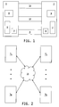
- the pairing and authentication process is carried out between only one medical device and one remote electronic device 2 to provide for secure wireless communication between only the two devices 1 and 2.
- the medical device communication system may include any number, N, of medical devices, 1 1 - 1 N , where N may be any positive integer, and any number, M, of remote electronic devices, 2 1 - 2 M , where M may be any positive integer.
- a medical device communication system may be established in which one or more medical devices, 1 1 - 1 N , may be configured for secure communications with one ore more remote electronic devices, 2 1 - 2 M and/or with any one or more of the remaining medical devices, 1 1 - 1 N .
- FIG. 3 a flowchart is shown of one illustrative embodiment of a pairing process for pairing a medical device 1 with a remote electronic device 2.
- the pairing process is illustrated and will be described in the context of a single medical device 1 and a single remote electronic device 2, it will be understood that the pairing process of FIG. 3 may be carried out between one or more medical devices and one or more remote electronic devices, between one or more medical devices and one or more other medical devices, and/or between one or more remote electronic devices and one or more other remote electronic devices.
- the flowchart of FIG. 3 is partitioned into the various entities and device/electrical components that carry out the various acts of the pairing process.
- a person 12 conducting the pairing process will carry out some of the acts
- the control unit 6 of the medical device 1 will carry out some of the acts with the aid of the user interface 8
- the communications module 3 of the medical device 1 will carry out some of the acts
- the communications module 4 of the remote electronic device 2 will carry out some of the acts
- the control unit 7 of the remote electronic device 2 will carry out some of the acts with the aid of the user interface 9.
- a precondition for the pairing process of FIG. 3 in embodiments in which the pairing and authentication process may be carried out only between a single medical device 1 and a single remote electronic device 2, is that on the side of the medical device 1 no remote electronic device 2 is currently paired.
- Step 20 denotes the start of the pairing process, and thereafter at step 21 the medical device 1 and the remote device 2 are placed in range relative to each other by a user 12 for wireless communication and connection, although this disclosure contemplates embodiments in which the pairing process and/or the subsequent authentication process and/or the subsequent binding process may be carried out, at least in part, via a wired connection and/or via an alternate wireless connection, i.e., other than via the communication modules 3 and 4.
- step 22 the remote electronic device 2 is set into pairable mode, which begins the pairing phase.
- the pairing phase is illustratively optional, and this disclosure accordingly contemplates embodiments in which the pairing phase is omitted from the overall pairing and authenticating process.
- the user 12 illustratively sets the remote electronic device 2 into pairable mode by pressing a specific key, a combination of keys or a specified sequence of keys on the remote device 2 on power up, or by entering a specific key, a combination of keys or sequence of keys or entering a specific pairing menu, after power up. Pressing the specific key or keys activates a specific pairing firmware on the communication module 4 as well as on the control unit 7 of the remote electronic device 2.
- the communication module 4 sets the remote electronic device 2 in step 23 in pairable mode, i.e., in the mode of being device inquirable and connectable, in order to be discoverable by the medical device 1.
- the control unit 7 illustratively (and optionally) controls the user interface 9 of the remote device 2 to display a message indicating that the pairing process, or that the pairing and authentication process, has begun, e.g., a message such as "Starting Pairing and Authentication Process" or a similar message.
- the control unit 7 of the remote electronic device 2 attempts to communicate with the medical device 1 via the transport portion of the security and transport layer 10. Communication via the transport portion of the security and transport layer 10 will, however, not be possible until successful completion of the pairing phase, i.e., upon successful pairing of the communication modules 3, 4 of the medical device 1 and the remote electronic device 2.
- step 26 the medical device 1 is set into pairing mode.
- the user 12 sets the medical device 1 into the pairing mode by selecting a corresponding pairing menu which is displayed on the user interface 8 of the medical device 1 under the control of the control unit 6, or by pressing a specific key, a combination of keys or a specified sequence of keys on the medical device 1.
- the control unit 6 of the medical device 1 then starts the actual pairing process in step 27 and instructs the communication module 3 of the medical device 1 in step 28 to initiate and perform a remote device discovery inquiry.
- the communication module 3 searches during the remote device discovery inquiry for potential pairable remote electronic devices 2 in range, and obtaining in the process the virtual addresses of the communication modules 4 of any remote electronic devices 2 in range.
- the discovered remote electronic devices 2 are illustratively filtered in one embodiment so that only pairable remote electronic devices 2, i.e., remote electronic devices 2 that are set in the pairable mode, are found.
- the discovered remote electronic devices may be filtered such that only devices with a special configuration, e.g., a special address, a friendly or service name, that offers a special service(s), etc., are found.
- other electronic devices which are not aimed at being connected with the medical device 1, can be filtered out.
- the communication module 3 sends the found remote electronic devices 2, i.e., the virtual or special address, friendly name, service name, special service(s), etc., of the found remote electronic devices 2, to the control unit 6 of the medical device 1.
- the control unit 6 of the medical device 1 checks in step 31 if any remote electronic devices 2 have been found during the remote device discovery inquiry of steps 28-30. If no remote electronic devices 2 have been found, the control unit 6 illustratively controls the user interface 8 of the medical device 1 to display in step 32 a message indicating that no remote electronic devices were found during the remote device discovery inquiry, e.g., a message such as "No remote devices found" or a similar message. With no remote devices to pair with, the pairing process then ends. If, on the other hand, one or more remote electronic devices 2 have been found during the remote device discovery inquiry, the control unit 6 then controls the user interface 8 of the medical device 1 at step 33 to display the one or more discovered, pairable remote electronic devices 2 as a list on the user interface 8. Illustratively, although not necessarily, friendly names of the found remote electronic devices 2 are displayed on the user interface 8 at step 33, wherein the such friendly names may contain, in whole or in part, the serial numbers or other identification codes of the discovered remote electronic devices 2.
- step 34 the user 12 selects a remote electronic device 2 from the list of discovered remote devices 2 that is displayed on the user interface 8 of the medical device 1.
- the control unit 6 of the medical device 1 then sends identifying information of the selected remote electronic device 2, e.g., the address of the communication module of the remote electronic device 2 that has been selected, to the communication module 3 in step 35, and thereafter at step 36 the control unit 6 instructs the communication module 3 of the medical device 1 to begin pairing with the communication module 4 of the remote electronic device 2 by requesting authentication.
- the medical device 1 may not be operable at steps 27-36 to scan for, and select from, potential pairable remote electronic devices 2 in range, and instead the control unit 6 may be operable to control the user interface 8 to request the user to manually provide an identifying information, e.g., a virtual address, to the control unit 6, e.g., via a keypad or other conventional data entry mechanism, of a particular remote electronic device 2 that is to be paired with the medical device 1.
- an identifying information e.g., a virtual address
- Pairing between the communication module 3 and the communication module 4 begins at steps 36 and 37 respectively, and is conducted on the communications layer 5.
- the communication modules 3, 4 of the medical device 1 and the remote electronic device 2 are both prompted at steps 38 and 39 respectively to provide a PIN code.
- the PIN code is a fixed code that is hard-coded on each of the communication modules 3, 4.
- the PIN code for each module 3, 4 may be stored in a memory of the respective control units 6, 7, or otherwise provided to the communication modules 3, 4 from an external source.
- the PIN codes may generally comprise any number of alphanumeric characters, purely numeric characters, purely alphabetic characters, purely symbolic characters or any combination thereof.
- the communication module 3 initiates pairing with the communication module 4 by requesting authentication with the PIN code.
- step 40 the communication module 3 sends the pairing result to the control unit 6 of the medical device 1, the pairing result comprising the identity, e.g., the communication address, of the remote electronic device 2 based on the PIN code provided by the control module 4 of the remote electronic device 2.
- steps 41, 42, 43 the control unit 6 and the communication module 3 of the medical device 1, and the communication module 4 of the remote electronic device 2, each check if the pairing has been successful, i.e. if the identity, e.g., the communication address, of the other device 2, 1, has been authenticated successfully. On successful authentication, i.e.
- the communication modules 3, 4 of the medical device 1 and of the remote electronic device 2 respectively each generate a unique link key or a plurality of link keys and store the link key or keys and the communication address of the other device 2, 1 locally in a memory of the medical device 1 and of the remote device 2, respectively (steps 44 and 45).
- the local memory in each device 1, 2 in which the link key or keys and the communication address of the other device 2, 1 are stored is a non-volatile memory such that the stored information will be retained in the respective memories until overwritten.
- the local memory in each device 1, 2 in which the link key or keys and the communication address of the other device 2, 1 are stored may be a volatile memory, in which case the pairing process, including the exchange and storage of the link keys and communication addresses, will be required after device power up.
- the control unit of the medical device 1 is operable in step 46 to control the user interface 8 to display a message indicating that the pairing process was not successfully completed, e.g., a message such as "Process not successful" or other message.
- the communication module 3 of the medical device 1 transitions to an idle state, and in step 47 the control unit 6 exits the pairing menu displayed on the user interface 8 of the medical device 1 and powers off the communication module 3.
- the pairing process within the medical device 1 ends.
- the communication module 4 reacts to the unsuccessful pairing determination by setting the remote electronic device 2 back into pairable mode, i.e. by returning to step 23, in order to be again discoverable by the medical device 1.
- the communication module 3 of the medical device 1 makes itself wirelessly connectable via the communication layer 5 in step 49.
- the communication module 4 of the remote electronic device 2 attempts to establish a wireless connection with the communication module 3 of the medical device 1.
- a wireless connection via the communications layer 5, using a conventional communication protocol, e.g., BlueTooth® communication protocol or other desired communication protocol, is then actually established in step 51.
- the medical device 1 and the remote device are then wirelessly connected (item 52), and with the pairing of the medical device 1 and the remote electronic device 2 completed wireless communication between the two devices 1, 2 is then possible via the communication layer 5.
- the communication module 4 of the remote electronic device 2 was first put into a pairable mode by the user 12, and the control unit 6 and communication module 3 of the medical device 1 thereafter controlled the pairing process.
- the communication module 3 of the medical device 1 may instead be put into a pairable mode by the user 12, and the control unit 7 and communication module 4 of the remote electronic device 2 may thereafter control the pairing process.
- the pairing process has been described as occurring between a device that has been put in the pairing mode, e.g., a menu-driven pairing mode, and another device that has been put in a pairable mode, e.g., a discoverable device, by a user 12, this disclosure contemplates embodiments in which a license or certificate is required to put a device in the pairable mode.
- the license or certificate would carry a serial number, communication address, a combination thereof or the like which would be required to identify the device for pairing.
- such a license or certificate may carry all or part of the PIN code, or information relating to the PIN code, and in this embodiment a device could be put in a pairing mode or be put in a pairable mode, but the pairing process could not be completed without the PIN code or PIN code information.
- the pairing and authentication process is continued in step 53 with the authentication phase, the authentication phase being depicted in FIG. 4 as a schematic representation in the form of a flowchart.
- the various steps/items of the flowchart of FIG. 4 are illustratively carried out by a combination of the user 12, the control unit 6 and user interface 8 of the medical device 1, the communication modules 3 and 4 of the medical device 1 and the remote electronic device 2 respectively and the control unit 7 and user interface 9 of the remote electronic device 2.
- Item 53 represents the completed pairing phase, and after completion of the pairing phase the control unit 7 of the remote electronic device 2 is able to establish wireless communication with the control unit 6 of the medical device 1 via the transport portion of the security and transport layer 10 in steps 54 and 55.
- the medical device 1 and the remote electronic device 2 are then connected via the transport portion of the security and transport layer 10 (item 56).
- the control unit 6 of the medical device 1 illustratively generates a PIN code and in step 59 the control unit 6 controls the user interface 8 on the medical device 1 to display the generated PIN code.
- the PIN code may be purely numeric, purely alphabetic, purely symbolic or any combination thereof, and may have any desired character length.
- the control unit 6 of the medical device 1 then waits for subsequent authentication of the remote electronic device 2.
- step 60 the control unit 7 of the remote device 2 controls the user interface 9 to display a suitable message prompting the user 12 to provide the PIN code that is currently displayed on the user interface 8 of the medical device 1 to the control unit 7 of the remote electronic device 2, e.g., by manually entering the currently displayed PIN code into the remote electronic device 2 via a keypad or other conventional information input mechanism.
- step 61 the user 12 reads the PIN code displayed on the user interface 8 of the medical device 1 and provides in step 62 the PIN code to the control unit 7 of the remote electronic device 2.
- the PIN code generated by the control unit 6 of the medical device 1 may instead be provided to the control unit 7 of the remote electronic device 2 by a mechanism other than manual entry by the user 12.
- the PIN code may be exchanged between the two devices 1, 2 via a suitable wireless data exchange mechanism, e.g., RFID or the like, or via a wired connected between input and output data ports of the control unit 7 and the control unit 6 respectively.
- the complete PIN code may not be generated solely by the control unit 6 of the medical device 1, and may instead be generated in part by the control unit 6 and in part by the control unit 7 of the remote electronic device 2.
- the control unit 7 may be operable to assemble or otherwise determine the complete PIN code based on the portion of the PIN code generated by the control unit 6 and provided to the control unit 7 via any of the mechanisms described above and also based on the portion of the PIN code generated by the control unit 7.
- the complete PIN code will not be known by the control unit 6 of the medical device 1 until it is wirelessly transmitted, via the communication modules 4 and 3 respectively, by the control unit 7 of the remote electronic device 2 back to the control unit 6 of the medical device 1.
- the control unit 6 of the medical device 1 and the control unit 7 of the remote electronic device 2 check the authentication of the PIN code that was provided to the control unit 7 as described above.
- the control unit 6 of the medical device 1 For authentication of the PIN code the control unit 6 of the medical device 1 generates a signature from the generated PIN code, for example by applying a symmetric encryption method such as AES, DES, IDEA, Blowfish or other symmetric or non-symmetric encryption method.
- the control unit 7 of the remote electronic device 2 also generates a signature based on the entered PIN code, for example by applying the same encryption as the medical device 1.
- the control unit 6 of the medical device 1 attaches the signature to a data packet and sends it to the control unit 7 of the remote electronic device 2 via the communication modules 3, 4 using the transport portion of the security and transport layer 10.
- the control unit 7 of the remote electronic device 2 checks if the signature which is attached to the sent data packet is the same as the signature it has generated itself. If the signatures are the same, then authentication of the PIN code has been successful.
- the control unit 6 of the medical device 1 then generates one or more strong keys.
- the control unit 7 of the remote electronic device 2 may request delivery of such one or more strong keys from the medical device 1.
- both devices 1 and 2 may each generate one or more strong keys.
- the control unit 6 of the medical device 1 encrypts the one or more strong keys it has generated, for example by applying a symmetric encryption method such as AES, DES, IDEA, Blowfish or other symmetric or non-symmetric encryption method, and sends the one or more encrypted strong keys to the control unit 7 of the remote electronic device 2 via the communication modules 3, 4 using the transport portion of the security and transport layer 10.
- a symmetric encryption method such as AES, DES, IDEA, Blowfish or other symmetric or non-symmetric encryption method
- the control unit 7 of the remote electronic device 2 then decrypts the one or more encrypted strong keys received from the control unit 6 of the medical device 1. Upon successful authentication of the one or more strong keys, the strong key exchange phase is completed. The control units 6 and 7 thereafter use the strong keys to generate and check the signatures for each data packet sent between the devices 1 and 2.
- the control units 6 and 7 exchange device identification information, e.g., device serial numbers or other device identification codes. Alternatively, the control units 6 and 7 may exchange device identification information at other times during the pairing and authentication process. In any case, other authentication methods can be applied alternatively or additionally to either of the authentication of the PIN code and the authentication of the one or more strong keys.
- Each control unit 6, 7 of the medical device 1 and the remote electronic device 2 respectively checks in steps 65 and 66 if the authentication process performed in steps 63 and 64 has been successful.
- the control unit 6 and the control unit 7 each store in steps 67 and 68 the one or more strong keys in a memory of the respective device 1, 2.
- the memories in which the one or more strong keys are stored are non-volatile.
- the memories in which the one or more strong keys are stored are volatile, in which case the authentication phase illustrated in FIG. 4 must be executed at each power up of the devices 1, 2.
- the one or more strong keys may be stored in the memory of either device 1, 2 in encrypted form.
- control unit 6 of the medical device 1 and the control unit 7 of the remote electronic device 2 may each also control their respective user interfaces 8, 9 to display a message in steps 67 and 68 indicating that the authentication process has been successful.
- control unit 7 of the remote electronic device 2 may also control the user interface 9 at step 68 to prompt the user 12 to restart the remote electronic device 2, and/or the control unit 6 of the medical device 1 may control the user interface 8 to prompt the user 12 to restart the medical device 1, although a restart of the medical device 1 and/or remote electronic device 2 may be omitted in other embodiments.
- step 70 does not advance to step 71 but instead loops back to step 58 where the control unit 6 of the medical device 1 is operable to generate a new PIN code after which the authentication process proceeds as described above.
- control unit 7 of the remote electronic device 2 determines that a power off of the remote electronic device has been requested or a timeout has occurred without user intervention following an unsuccessful authentication attempt
- the control unit 7 is operable at step 72 to power off the remote electronic device 2.
- the control unit 6 of the medical device 1 determines that the user 12 has exited the process or a timeout has occurred after an unsuccessful authentication attempt
- the control unit 6 instructs the communication module 3 at step 74 to disconnect from the communication module 4. Thereafter in steps 75 and 76, the communication modules 3 and 4 disconnect from each other, thereby resulting in disconnection of the communications layer 5 (item 77).
- control unit 6 instructs the communication module 3 at step 78 to unpair from the communication module 4 of the remote electronic device 2, after which the communication module 3 unpairs from the communication module 4 at step 79.
- control unit 6 also illustratively controls the user interface 8 of the medical device 1 at step 80 to display a message indicating that the authentication process was not successful. Thereafter at step 81 the control unit 6 controls the user interface 8 to exit the pairing and authentication menu and to then power off the communication module 3.
- control unit 6 of the medical device 1 generated the PIN code and thereafter the control unit 7 of the remote electronic device 2 controlled authentication of the PIN code entered into the remote electronic device 2 and controlled authentication of one or more strong keys that were generated by the control unit 6.
- control unit 7 of the remote electronic device 2 may instead generate the PIN code and the control unit 6 of the medical device 1 may control authentication of the PIN code and thereafter control authentication of the one or more strong keys.
- the pairing and authentication process is continued in step 69 with an optional binding phase, the binding phase being depicted in FIG. 5 as a schematic representation in the form of a flowchart.
- the various steps/items of the flowchart of FIG. 5 are illustratively carried out by a combination of the control unit 6 and user interface 8 of the medical device 1, the communication modules 3 and 4 of the medical device 1 and the remote electronic device 2 respectively and the control unit 7 and user interface 9 of the remote electronic device 2.
- Item 69 represents the completed authentication phase, and after completion of the authentication phase the control unit 7 of the remote electronic device 2 is able to establish wireless communication with the control unit 6 of the medical device 1 via the application layer 11 in steps 85 and 86.
- the medical device 1 and the remote electronic device 2 are then connected via the application layer 11 (item 87). Thereafter in steps 88 and 89, the control unit 7 of the remote electronic device 2 illustratively requests the service version of one operating mode of the remote electronic device 2 from the control unit 6 of the medical device 1.
- a version number or code of instructions that are stored in a memory of the remote electronic device 2 and executable by the control unit 7 to operate the remote electronic device 2 in accordance with the one operating mode is stored in the memories of the medical device 1 and the remote electronic device 2.
- the control unit 6 of the medical device 1 is operable at step 88 to provide the version number or code of the one operating mode of the remote electronic device 2 to the control unit 7 of the remote electronic device 2, which is then operable at step 90 to compare the sent version number or code with the corresponding version number or code stored in the memory of the remote electronic device 2. If the two version numbers or codes match, the binding process advances to steps 91 and 92.
- the control unit 7 of the remote electronic device 2 illustratively requests the service version of another operating mode of the remote electronic device 2 from the control unit 6 of the medical device 1.
- a version number or code of instructions that are stored in a memory of the remote electronic device 2 and executable by the control unit 7 to operate the remote electronic device 2 in accordance with the another operating mode is stored in the memories of the medical device 1 and the remote electronic device 2.
- the control unit 6 of the medical device 1 is operable at step 92 to provide the version number or code of the another operating mode of the remote electronic device 2 to the control unit 7 of the remote electronic device 2, which is then operable at step 93 to compare this sent version number or code with the corresponding version number or code stored in the memory of the remote electronic device 2. If these two version numbers or codes match, the binding process advances to step 94 where the control unit 7 of the remote electronic device 2 generates a pass code, and thereafter at step 95 the control unit 7 sets a binding flag in a memory of the remote electronic device 2. In one embodiment, the control unit 7 is operable to set the binding flag in a non-volatile memory of the remote electronic device 2.
- control unit 7 may be operable at step 95 to set the binding flag in a volatile memory of the remote electronic device 2, in which case the binding phase of FIG. 5 must be repeated with each power up of the remote electronic device 2.
- steps 90 or 93 result in a mismatch of the version numbers or codes, the control unit 7 of the remote electronic device 2 generates a fail code at step 96.
- the pass/fail information is sent by the control unit 7 of the remote electronic device 2 in steps 94 and 96 to the control unit 6 of the medical device 1 via the application layer 11, which is received by the control unit 6 in step 97. Thereafter in step 98, the control unit 6 of the medical device 1 processes the pass/fail information and if the pass code was generated in step 94 the control unit 6 sets a binding flag in a memory of the medical device 1 in step 99 and thereafter controls the user interface 8 in step 100 to display a message indicating that the binding phase was successful. In one embodiment, the control unit 6 is operable to set the binding flag in a non-volatile memory of the medical device 1.
- control unit 7 may be operable in step 99 to set the binding flag in a volatile memory of the medical device 1, in which case the binding phase of FIG. 5 must be repeated with each power up of the medical device 1. If, on the other hand, the control unit 6 of the medical device 1 determines in step 98 that the fail code was generated in step 96 the control unit 6 controls the user interface 8 in step 101 to display a message indicating that the binding phase was not successful.
- the control unit 7 of the remote electronic device 2 is operable in step 102 to instruct the control unit 6 of the medical device 1 to disconnect the application layer 11, and in steps 102 and 103 the control units 6 and 7 together disconnect the application layer 11 (item 104).
- the control unit 6 of the medical device 1 is operable in step 105 to instruct the communication module 3 to disconnect from the communication module 4 of the remote electronic device 2.
- the communication modules 3 and 4 disconnect from each other, thereby resulting in disconnection of the communications layer 5 (item 109).
- the control unit 6 is operable in step 108 to remove the authentication data, e.g., the one or more strong keys, from the memory of the medical device 1.
- the control unit 6 of the medical device 1 instructs the communication module 3 to unpair from the communication module 4 of the remote electronic device 2, after which the communication module 3 unpairs from the communication module 4 at step 111.
- the control unit 7 of the remote electronic device 2 is operable following step 102 to control the user interface 9 to display in step 112 a message indicating that the binding process was successful. If, on the other hand, the fail code was set in step 96, the control unit 7 of the remote electronic device 2 is operable following step 102 to remove in step 113 the authentication data, e.g., the one or more strong keys, from the memory of the remote electronic device 2. Thereafter in step 114, the control unit 7 is operable to control the user interface 9 of the remote electronic device 2 to display a message indicating that the binding process was not successful.
- the authentication data e.g., the one or more strong keys
- step 115 indicates that the medical device 1 and the remote electronic device 2 are authenticated for future use and communication and connection via the application layer 11 after power up.
- the one or more strong keys are used, which is stored in the memories of the medical device 1 and the remote electronic device 2.
- the control unit 7 of the remote electronic device 2 was operable to compare service version numbers or codes for two different operating modes of the remote electronic device 2.
- the two different operating modes may be a command mode in which the remote electronic device 2 computes a recommended therapy to be administered by the medical device, e.g., an amount of a drug to be infused or otherwise delivered, and a remote terminal mode in which the remote electronic device 2 is operable to control the operation of the medical device 1 in real time. It will be understood that the binding phase illustrated in FIG.
- the remote electronic device 5 may alternatively be configured to compare service version numbers or codes for more, fewer and/or other operating modes of the remote electronic device, and modifications to the illustrated process to accomplish this would be a mechanical step for a person of ordinary skill in the art. It will be further understood that information exchanged between the medical device 1 and the remote electronic device 2 via the application layer 11 during the binding phase may alternatively or additionally be encrypted using any conventional encrypting techniques.
- control unit 7 of the remote electronic device 2 controlled comparisons of the service version numbers or codes and setting of the corresponding pass and fail codes.
- control unit 6 of the medical device 1 may instead control the comparisons of the service version numbers or codes and setting of the corresponding pass and fail codes.
- the pairing and authentication process described herein will typically be initiated before the first connection between a medical device 1 and a remote electronic device 2 in order to enable secure communication between the medical device 1 and the remote electronic device 2. The process will also typically be performed upon replacement of either the medical device 1 or the remote electronic device 2.
- control unit 6 of the medical device 1 controls portions of the process and is therefore the master in such portions of the process while the control unit 7 of the remote electronic device 2 is the slave in such portions of the process, and the control unit 7 of the remote electronic device 2 controls other portions of the process and is therefore the master in such other portions of the process while the control unit 6 is the slave in such other portions of the process.
- this disclosure contemplates alternate embodiments in which the master/slave relationships of the control units 6 and 7 are reversed in whole or in part during one or more phases of the pairing and authentication process.
Landscapes
- Engineering & Computer Science (AREA)
- Health & Medical Sciences (AREA)
- Biomedical Technology (AREA)
- Computer Security & Cryptography (AREA)
- Computer Networks & Wireless Communication (AREA)
- Signal Processing (AREA)
- Epidemiology (AREA)
- General Business, Economics & Management (AREA)
- Business, Economics & Management (AREA)
- General Health & Medical Sciences (AREA)
- Medical Informatics (AREA)
- Primary Health Care (AREA)
- Public Health (AREA)
- Computer Hardware Design (AREA)
- Computing Systems (AREA)
- General Engineering & Computer Science (AREA)
- Selective Calling Equipment (AREA)
- Infusion, Injection, And Reservoir Apparatuses (AREA)
Description
- The present invention relates generally to medical devices configured to wirelessly communicate with remote electronic devices, and more specifically to pairing and authenticating one or more medical devices and one or more remote devices for subsequent secure wireless communications.
- It is generally known to provide for wireless communications between a medical device, such as an ambulatory medical device, and a remote electronic device. It is desirable with such arrangements to configure the medical device and the remote electronic device in a manner that provides for secure wireless communications between the two devices. It is further desirable in systems that may include a plurality of medical devices and/or a plurality of remote electronic devices to configure one or more of the medical devices and one or more of the remote electronic devices in a manner that provides for secure wireless communications between various combinations of the devices.
- The present invention may comprise one or more of the features recited in the attached claims, and/or one or more of the following features and combinations thereof. A method for authenticating a medical device and a remote electronic device that are placed in communication range relative to each other may comprise generating at least a portion of a PIN code by one of the medical device and the remote electronic device, capturing the at least a portion of the generated PIN code with the other of the medical device and the remote electronic device, checking authentication of the PIN code, which is based at least in part on the captured at least a portion of the generated PIN code, by the one of the medical device and the remote electronic device, generating at least one strong key by one of the medical device and the remote electronic device, sending the at least one strong key encrypted to the other of the medical device and the remote electronic device, checking authentication of the sent at least one strong key by the one of the medical device and the remote electronic device, and upon successful authentication of the PIN code and the at least one strong key, storing the at least one strong key in a memory of the medical device and in a memory of the remote electronic device.
- In one illustrative embodiment, generating at least a portion of a PIN code may comprise generating a complete PIN code by the one of the medical device and the remote electronic device. Capturing the at least a portion of the generated PIN code comprises capturing the complete PIN code with the other of the medical device and the remote electronic device. Checking authentication of the PIN code comprises checking authentication of the captured complete PIN code by the one of the medical device and the remote electronic device. In an alternate embodiment, the method may further comprise generating at least another portion of the PIN code by the other of the medical device and the remote electronic device, and forming by the other of the medical device and the remote electronic device a complete PIN code based on the at least a portion of the PIN code and the at least another portion of the PIN code. In this embodiment, checking authentication of the PIN code may comprise checking authentication of the complete PIN code by the one of the medical device and the remote electronic device.
- In one illustrative embodiment, capturing the at least a portion of the generated PIN code may comprise displaying the at least a portion of the generated PIN code by the one of the medical device and the remote electronic device, and instructing via a display of the other of the medical device and the remote electronic device manual input of the at least a portion of the generated PIN code into the other of the medical device and the remote electronic device. In an alternative embodiment, capturing the at least a portion of the generated PIN code may comprise one of sending the at least a portion of the generated PIN code by the one of the medical device and the remote electronic device to the other of the medical device and the remote electronic device and retrieving the at least a portion of the generated PIN code by the other of the medical device and the remote electronic device from the one of the medical device and the remote electronic device.
- The method may further comprise exchanging respective device identification codes between the medical device and the remote electronic device. The respective device identification codes may, for example, be exchanged between the medical device and the remote electronic device following authentication of the at least one strong key.
- Upon non-successful authentication of either of the PIN code and the at least one strong key, in one illustrative embodiment, the method may return to the step of generating at least a portion of a PIN code by one of the medical device and the remote electronic device. In an alternative embodiment, a message may be displayed on at least one of the medical device and the remote electronic device indicating that the authentication was not successful and the method may return to the step of displaying the at least a portion of the generated PIN code by the one of the medical device and the remote electronic device, upon non-successful authentication of either of the PIN code and the at least one strong key.
- The method may further comprise restarting the other of the medical device and the remote electronic device upon successful authentication of the PIN code and the at least one strong key.
- The method may further comprise performing a pairing phase prior to executing any of the steps of the method for authenticating. In one illustrative embodiment, the pairing phase may comprise setting the other of the medical device and the remote electronic device in a pairable mode in order to be discoverable by the one of the medical device and the remote electronic device, setting the one of the medical device and the remote electronic device in a pairing mode, performing a device discovery inquiry by the one of the medical device and the remote electronic device, displaying discovered devices resulting from the device discovery inquiry, upon user selection from the displayed discovered devices of the other of the medical device and the remote electronic device, pairing the one of the medical device and the remote electronic device with the other of the medical device and the remote electronic device, upon successful pairing generating a link key on the medical device and on the remote electronic device, storing the link key and a virtual address of the other of the medical device and the remote electronic device in a memory of the one of the medical device and the remote electronic device, and storing the link key and a virtual address of the one of the medical device and the remote electronic device in a memory of the other of the medical device and the remote electronic device, and connecting the medical device and the remote electronic device together.
- In one illustrative embodiment, BlueTooth® may be used as a communication protocol for communication between the medical device and the remote electronic device during the pairing phase.
- The method may further comprise filtering discovered devices resulting from the device discovery inquiry prior to displaying the discovered devices such that only discovered devices that are in the pairable mode are displayed for user selection. Alternatively or additionally, the method may further comprise filtering discovered devices resulting from the device discovery inquiry prior to displaying the discovered devices by comparing the discovered devices to entries of a predefined device list and displaying only the discovered devices that match entries on the predefined device list.
- The method may further comprise requesting authentication of the other of the medical device and the remote electronic device selected from the displayed discoverable devices. For such authentication, the one of the medical device and the remote electronic device and the other of the medical device and the remote electronic device may each provide a fixed PIN code.
- The method may further comprise performing a binding phase after executing all of the steps of the method for authenticating. The binding phase may comprise sending service versions of all operating modes of the remote electronic device by one of the medical device and the remote electronic device to the other of the medical device and the remote electronic device, upon a determination by the other of the medical device and the remote electronic device that the sent service versions are compatible with corresponding service versions stored in the memory of the other of the medical device and the remote electronic device, storing a pass flag in a memory of the medical device and in a memory of the remote electronic device, and upon a determination by the other of the medical device and the remote electronic device that at least one of the sent service versions is not compatible with a corresponding one of the service versions stored in the memory of the other of the medical device and the remote electronic device, removing the at least one strong key from the memory of the medical device and from the memory of the remote electronic device.
- A method may be provided for pairing a medical device and a remote electronic device that are placed in communication range relative to each other. The method may comprise setting one of the medical device and the remote electronic device in a pairing mode, performing a device discovery inquiry by the other of the medical device and the remote electronic device, displaying discovered devices resulting from the device discovery inquiry, upon user selection from the displayed discovered devices of the one of the medical device and the remote electronic device, pairing the other of the medical device and the remote electronic device with the one of the medical device and the remote electronic device, upon successful pairing generating a link key on the medical device and on the remote electronic device, storing the link key and a virtual address of the one of the medical device and the remote electronic device in a memory of the other of the medical device and the remote electronic device, and storing the link key and a virtual address of the other of the medical device and the remote electronic device in a memory of the one of the medical device and the remote electronic device, and connecting the medical device and the remote electronic device together.
- Illustratively, BlueTooth® may be used as a communication protocol for communication between the medical device and the remote electronic device.
- The method may further comprise filtering discovered devices resulting from the device discovery inquiry prior to displaying the discovered devices such that only discovered devices that are in the pairable mode are displayed for user selection. Alternatively or additionally, the method may further comprise filtering discovered devices resulting from the device discovery inquiry prior to displaying the discovered devices by comparing the discovered devices to entries of a predefined device list and displaying only the discovered devices that match entries on the predefined device list.
- The method may further comprise requesting authentication of the one of the medical device and the remote electronic device selected from the displayed discoverable devices. For such authentication, the one of the medical device and the remote electronic device and the other of the medical device and the remote electronic device may each provide a fixed PIN code.
- A method may be provided for binding a medical device and a remote electronic device that are placed in communication range relative to each other. The method may comprise sending service versions of all operating modes of the remote electronic device by one of the medical device and the remote electronic device to the other of the medical device and the remote electronic device, upon a determination by the other of the medical device and the remote electronic device that the sent service versions are compatible with corresponding service versions stored in the memory of the other of the medical device and the remote electronic device, storing a pass flag in a memory of the medical device and in a memory of the remote electronic device, and upon a determination by the other of the medical device and the remote electronic device that at least one of the sent service versions is not compatible with a corresponding one of the service versions stored in the memory of the other of the medical device and the remote electronic device, removing the at least one strong key from the memory of the medical device and from the memory of the remote electronic device.
-
-
FIG. 1 is a diagram of one illustrative embodiment of an abstract interconnection layer model for wireless communications between a medical device and a remote electronic device. -
FIG. 2 is a diagram illustrating pairing and authentication carried out between one or more medical devices and one or more other medical devices and/or one or more remote electronic devices. -
FIG. 3 is a flowchart of one illustrative embodiment of a pairing process for pairing a medical device with a remote electronic device. -
FIG. 4 is a flowchart of one illustrative embodiment of an authentication process for authenticating the medical device and the remote electronic device following a pairing process such as that illustrated inFIG. 3 -
FIG. 5 is a flowchart of one illustrative embodiment of a binding process that may follow the authentication process ofFIG. 4 . - For the purposes of promoting an understanding of the principles of the invention, reference will now be made to a number of illustrative embodiments shown in the attached drawings and specific language will be used to describe the same.
- Referring now to
FIG. 1 , amedical device 1 and a remoteelectronic device 2 are shown along with one illustrative embodiment of an abstract interconnection layer model for wireless communications between the twodevices medical device 1 may be, for example, an ambulatory medical device, although themedical device 1 may alternatively be or include a non-ambulatory medical device. Examples of such an ambulatorymedical device 1 may include, but should not be limited to, one or any combination of a medication delivery device such as an infusion pump, a glucose meter, a body fluid analyte sensor system including one or more subcutaneous and/or implanted body fluid analyte sensors, a remote terminal representing a remote infusion pump display on which data from the infusion pump is displayed to a user, or the like. The remoteelectronic device 2 may be or include, but should not be limited to, a conventional personal data assistant (PDA) device, an application specific remote electronic device that may be hand-held, attachable or mountable to clothing, configured to be worn by a person such as on or about a limb or portion thereof, on or about a head or portion thereof, or on or about a body or portion thereof, attachable to a key ring, or the like, a portable wireless communication device with an on-board glucose meter, a smart phone, a personal computer (PC), a laptop, notebook or similar computer, or the like. In one specific embodiment, which should not be considered to be limiting in any way, themedical device 1 is an insulin infusion pump and the remote electronic device is a hand-held, diabetes management unit. The functionality of themedical device 1 and the remoteelectronic device 2 may also be reversed, i.e., themedical device 1 may be one of the above devices mentioned as examples for a remoteelectronic device 2 and the remoteelectronic device 2 may be one of the above devices mentioned as examples for amedical device 1. - In the illustrated embodiment, the
medical device 1 includes awireless communication module 3 and the remoteelectronic device 2 also includes awireless communication module 4. Thewireless communication modules wireless communication modules wireless communication modules communication modules communication modules - The
medical device 1 and the remoteelectronic device 2 each further include aconventional control unit control units control units medical device 1 and the remoteelectronic device 2 each further include auser interface user interfaces - To provide for secure communications between the
medical device 1 and the remoteelectronic device 2, themedical device 1 and the remoteelectronic device 2 are mutually authenticated according to a process that will be referred to herein as pairing and authentication. In embodiments in which thewireless communication modules wireless communication modules - The pairing phase of the pairing and authentication process takes place between the
medical device 1 and the remoteelectronic device 2 via thecommunication layer 3 as described above. In the pairing phase, a trusted relationship between themedical device 1 and the remoteelectronic device 2 is established as will be described in detail hereinafter. Following successful pairing according to the pairing phase, themedical device 1 and the remoteelectronic device 2 are wirelessly connected by a security andtransport layer 10. Physically, the security andtransport layer 10 may form a single layer as illustrated inFIG. 1 , or may instead be partitioned into a security layer and a separate transport layer. - In either case, the authentication phase of the pairing and authentication process takes place between the
medical device 1 and the remoteelectronic device 2 via the security portion of the security andtransport layer 10. When the pairing and authentication process is successfully completed and themedical device 1 and the remoteelectronic device 2 thereafter communicate wirelessly in a secure manner, the transport portion of the security andtransport layer 10 is illustratively used for error recognition and retransmission of data. Following successful authentication according to the authentication phase, a secure link is established between themedical device 1 and the remoteelectronic device 2, and data can be transmitted between the twodevices application layer 11. - The binding phase of the pairing and authentication process takes place between the
medical device 1 and the remoteelectronic device 2 via theapplication layer 11. Following successful completion of the binding phase, the pairing and authentication process is complete, and themedical device 1 and the remoteelectronic device 2 may thereafter communicate wirelessly in a secure manner. Secure transmission of data between themedical device 1 and the remoteelectronic device 2 does not occur until a secure data transmission link is established according to the pairing and authentication process just described. - In the embodiment illustrated and described with respect to
FIG. 1 , the pairing and authentication process is carried out between only one medical device and one remoteelectronic device 2 to provide for secure wireless communication between only the twodevices FIG. 2 , the medical device communication system may include any number, N, of medical devices, 11 - 1N, where N may be any positive integer, and any number, M, of remote electronic devices, 21- 2M, where M may be any positive integer. In this embodiment, amultiple pairing process 15 is supported in which a single one of the medical devices 1J (J = 1 to N) may be paired and authenticated with any one or more of the M remote electronic devices, 21 - 2M, and/or with one or more of the remaining N-1 medical devices, 11 - 1N, a single one of the remote devices 1K (K = 1 to M) may be paired and authenticated with any one or more of the N medical devices and/or with one or more of the remaining M-1 remote electronic devices, 21 - 2M, any subset of the plurality of medical devices, 11- 1N, may be paired and authenticated with any subset of the plurality of remote electronic devices, 21- 2M and/or with one or more of the remaining medical devices, 11 - 1N, or any subset of the plurality of remote electronic devices, 21 - 2M, may be paired and authenticated with any subset of the plurality of medical devices, 11 - 1N and/or with one or more of the remaining remote electronic devices, 21 - 2M. Using this extended approach, a medical device communication system may be established in which one or more medical devices, 11 - 1N, may be configured for secure communications with one ore more remote electronic devices, 21 - 2M and/or with any one or more of the remaining medical devices, 11 - 1N. - Referring now to
FIG. 3 , a flowchart is shown of one illustrative embodiment of a pairing process for pairing amedical device 1 with a remoteelectronic device 2. Although the pairing process is illustrated and will be described in the context of a singlemedical device 1 and a single remoteelectronic device 2, it will be understood that the pairing process ofFIG. 3 may be carried out between one or more medical devices and one or more remote electronic devices, between one or more medical devices and one or more other medical devices, and/or between one or more remote electronic devices and one or more other remote electronic devices. In any case, the flowchart ofFIG. 3 is partitioned into the various entities and device/electrical components that carry out the various acts of the pairing process. Thus, for example, aperson 12 conducting the pairing process will carry out some of the acts, thecontrol unit 6 of themedical device 1 will carry out some of the acts with the aid of theuser interface 8, thecommunications module 3 of themedical device 1 will carry out some of the acts, thecommunications module 4 of the remoteelectronic device 2 will carry out some of the acts and thecontrol unit 7 of the remoteelectronic device 2 will carry out some of the acts with the aid of theuser interface 9. - Illustratively, a precondition for the pairing process of
FIG. 3 , in embodiments in which the pairing and authentication process may be carried out only between a singlemedical device 1 and a single remoteelectronic device 2, is that on the side of themedical device 1 no remoteelectronic device 2 is currently paired.Step 20 denotes the start of the pairing process, and thereafter atstep 21 themedical device 1 and theremote device 2 are placed in range relative to each other by auser 12 for wireless communication and connection, although this disclosure contemplates embodiments in which the pairing process and/or the subsequent authentication process and/or the subsequent binding process may be carried out, at least in part, via a wired connection and/or via an alternate wireless connection, i.e., other than via thecommunication modules - In
step 22 the remoteelectronic device 2 is set into pairable mode, which begins the pairing phase. The pairing phase is illustratively optional, and this disclosure accordingly contemplates embodiments in which the pairing phase is omitted from the overall pairing and authenticating process. In any case, theuser 12 illustratively sets the remoteelectronic device 2 into pairable mode by pressing a specific key, a combination of keys or a specified sequence of keys on theremote device 2 on power up, or by entering a specific key, a combination of keys or sequence of keys or entering a specific pairing menu, after power up. Pressing the specific key or keys activates a specific pairing firmware on thecommunication module 4 as well as on thecontrol unit 7 of the remoteelectronic device 2. Thecommunication module 4 then sets the remoteelectronic device 2 instep 23 in pairable mode, i.e., in the mode of being device inquirable and connectable, in order to be discoverable by themedical device 1. Atstep 24, thecontrol unit 7 illustratively (and optionally) controls theuser interface 9 of theremote device 2 to display a message indicating that the pairing process, or that the pairing and authentication process, has begun, e.g., a message such as "Starting Pairing and Authentication Process" or a similar message. Thereafter atstep 25, thecontrol unit 7 of the remoteelectronic device 2 attempts to communicate with themedical device 1 via the transport portion of the security andtransport layer 10. Communication via the transport portion of the security andtransport layer 10 will, however, not be possible until successful completion of the pairing phase, i.e., upon successful pairing of thecommunication modules medical device 1 and the remoteelectronic device 2. - In
step 26 themedical device 1 is set into pairing mode. Illustratively, theuser 12 sets themedical device 1 into the pairing mode by selecting a corresponding pairing menu which is displayed on theuser interface 8 of themedical device 1 under the control of thecontrol unit 6, or by pressing a specific key, a combination of keys or a specified sequence of keys on themedical device 1. Thecontrol unit 6 of themedical device 1 then starts the actual pairing process instep 27 and instructs thecommunication module 3 of themedical device 1 instep 28 to initiate and perform a remote device discovery inquiry. In one illustrative embodiment, thecommunication module 3 searches during the remote device discovery inquiry for potential pairable remoteelectronic devices 2 in range, and obtaining in the process the virtual addresses of thecommunication modules 4 of any remoteelectronic devices 2 in range. Instep 29 the discovered remoteelectronic devices 2 are illustratively filtered in one embodiment so that only pairable remoteelectronic devices 2, i.e., remoteelectronic devices 2 that are set in the pairable mode, are found. Alternatively or additionally, the discovered remote electronic devices may be filtered such that only devices with a special configuration, e.g., a special address, a friendly or service name, that offers a special service(s), etc., are found. In any case, other electronic devices, which are not aimed at being connected with themedical device 1, can be filtered out. Instep 30 thecommunication module 3 sends the found remoteelectronic devices 2, i.e., the virtual or special address, friendly name, service name, special service(s), etc., of the found remoteelectronic devices 2, to thecontrol unit 6 of themedical device 1. - The
control unit 6 of themedical device 1 checks instep 31 if any remoteelectronic devices 2 have been found during the remote device discovery inquiry of steps 28-30. If no remoteelectronic devices 2 have been found, thecontrol unit 6 illustratively controls theuser interface 8 of themedical device 1 to display in step 32 a message indicating that no remote electronic devices were found during the remote device discovery inquiry, e.g., a message such as "No remote devices found" or a similar message. With no remote devices to pair with, the pairing process then ends. If, on the other hand, one or more remoteelectronic devices 2 have been found during the remote device discovery inquiry, thecontrol unit 6 then controls theuser interface 8 of themedical device 1 atstep 33 to display the one or more discovered, pairable remoteelectronic devices 2 as a list on theuser interface 8. Illustratively, although not necessarily, friendly names of the found remoteelectronic devices 2 are displayed on theuser interface 8 atstep 33, wherein the such friendly names may contain, in whole or in part, the serial numbers or other identification codes of the discovered remoteelectronic devices 2. - Thereafter in
step 34, theuser 12 selects a remoteelectronic device 2 from the list of discoveredremote devices 2 that is displayed on theuser interface 8 of themedical device 1. Thecontrol unit 6 of themedical device 1 then sends identifying information of the selected remoteelectronic device 2, e.g., the address of the communication module of the remoteelectronic device 2 that has been selected, to thecommunication module 3 instep 35, and thereafter atstep 36 thecontrol unit 6 instructs thecommunication module 3 of themedical device 1 to begin pairing with thecommunication module 4 of the remoteelectronic device 2 by requesting authentication. - Alternatively, the
medical device 1 may not be operable at steps 27-36 to scan for, and select from, potential pairable remoteelectronic devices 2 in range, and instead thecontrol unit 6 may be operable to control theuser interface 8 to request the user to manually provide an identifying information, e.g., a virtual address, to thecontrol unit 6, e.g., via a keypad or other conventional data entry mechanism, of a particular remoteelectronic device 2 that is to be paired with themedical device 1. - Pairing between the
communication module 3 and thecommunication module 4 begins atsteps communication modules medical device 1 and the remoteelectronic device 2 are both prompted atsteps communication modules module respective control units communication modules communication module 3 initiates pairing with thecommunication module 4 by requesting authentication with the PIN code. Instep 40, thecommunication module 3 sends the pairing result to thecontrol unit 6 of themedical device 1, the pairing result comprising the identity, e.g., the communication address, of the remoteelectronic device 2 based on the PIN code provided by thecontrol module 4 of the remoteelectronic device 2. In steps 41, 42, 43 thecontrol unit 6 and thecommunication module 3 of themedical device 1, and thecommunication module 4 of the remoteelectronic device 2, each check if the pairing has been successful, i.e. if the identity, e.g., the communication address, of theother device communication modules medical device 1 and of the remoteelectronic device 2 respectively each generate a unique link key or a plurality of link keys and store the link key or keys and the communication address of theother device medical device 1 and of theremote device 2, respectively (steps 44 and 45). Illustratively, the local memory in eachdevice other device device other device - If the pairing has not been successful in
steps medical device 1 is operable instep 46 to control theuser interface 8 to display a message indicating that the pairing process was not successfully completed, e.g., a message such as "Process not successful" or other message. Atstep 48, thecommunication module 3 of themedical device 1 transitions to an idle state, and instep 47 thecontrol unit 6 exits the pairing menu displayed on theuser interface 8 of themedical device 1 and powers off thecommunication module 3. Aftersteps medical device 1 ends. In the remoteelectronic device 2, thecommunication module 4 reacts to the unsuccessful pairing determination by setting the remoteelectronic device 2 back into pairable mode, i.e. by returning to step 23, in order to be again discoverable by themedical device 1. - Upon successful pairing and link key storage the
communication module 3 of themedical device 1 makes itself wirelessly connectable via the communication layer 5 instep 49. Then instep 50 thecommunication module 4 of the remoteelectronic device 2 attempts to establish a wireless connection with thecommunication module 3 of themedical device 1. A wireless connection via the communications layer 5, using a conventional communication protocol, e.g., BlueTooth® communication protocol or other desired communication protocol, is then actually established instep 51. Themedical device 1 and the remote device are then wirelessly connected (item 52), and with the pairing of themedical device 1 and the remoteelectronic device 2 completed wireless communication between the twodevices - In the pairing process described with reference to
FIG. 3 , thecommunication module 4 of the remoteelectronic device 2 was first put into a pairable mode by theuser 12, and thecontrol unit 6 andcommunication module 3 of themedical device 1 thereafter controlled the pairing process. In alternative embodiments, thecommunication module 3 of themedical device 1 may instead be put into a pairable mode by theuser 12, and thecontrol unit 7 andcommunication module 4 of the remoteelectronic device 2 may thereafter control the pairing process. In either case, while the pairing process has been described as occurring between a device that has been put in the pairing mode, e.g., a menu-driven pairing mode, and another device that has been put in a pairable mode, e.g., a discoverable device, by auser 12, this disclosure contemplates embodiments in which a license or certificate is required to put a device in the pairable mode. In such embodiments, the license or certificate would carry a serial number, communication address, a combination thereof or the like which would be required to identify the device for pairing. Alternatively still, such a license or certificate may carry all or part of the PIN code, or information relating to the PIN code, and in this embodiment a device could be put in a pairing mode or be put in a pairable mode, but the pairing process could not be completed without the PIN code or PIN code information. - In any case, the pairing and authentication process is continued in
step 53 with the authentication phase, the authentication phase being depicted inFIG. 4 as a schematic representation in the form of a flowchart. As withFIG. 3 , the various steps/items of the flowchart ofFIG. 4 are illustratively carried out by a combination of theuser 12, thecontrol unit 6 anduser interface 8 of themedical device 1, thecommunication modules medical device 1 and the remoteelectronic device 2 respectively and thecontrol unit 7 anduser interface 9 of the remoteelectronic device 2.Item 53 represents the completed pairing phase, and after completion of the pairing phase thecontrol unit 7 of the remoteelectronic device 2 is able to establish wireless communication with thecontrol unit 6 of themedical device 1 via the transport portion of the security andtransport layer 10 insteps medical device 1 and the remoteelectronic device 2 are then connected via the transport portion of the security and transport layer 10 (item 56). Thereafter instep 58, thecontrol unit 6 of themedical device 1 illustratively generates a PIN code and instep 59 thecontrol unit 6 controls theuser interface 8 on themedical device 1 to display the generated PIN code. Illustratively, the PIN code may be purely numeric, purely alphabetic, purely symbolic or any combination thereof, and may have any desired character length. In any case, thecontrol unit 6 of themedical device 1 then waits for subsequent authentication of the remoteelectronic device 2. - In
step 60, thecontrol unit 7 of theremote device 2 controls theuser interface 9 to display a suitable message prompting theuser 12 to provide the PIN code that is currently displayed on theuser interface 8 of themedical device 1 to thecontrol unit 7 of the remoteelectronic device 2, e.g., by manually entering the currently displayed PIN code into the remoteelectronic device 2 via a keypad or other conventional information input mechanism. Instep 61 theuser 12 reads the PIN code displayed on theuser interface 8 of themedical device 1 and provides instep 62 the PIN code to thecontrol unit 7 of the remoteelectronic device 2. In alternative embodiments, the PIN code generated by thecontrol unit 6 of themedical device 1 may instead be provided to thecontrol unit 7 of the remoteelectronic device 2 by a mechanism other than manual entry by theuser 12. For example, the PIN code may be exchanged between the twodevices control unit 7 and thecontrol unit 6 respectively. In other alternate embodiments, the complete PIN code may not be generated solely by thecontrol unit 6 of themedical device 1, and may instead be generated in part by thecontrol unit 6 and in part by thecontrol unit 7 of the remoteelectronic device 2. In such cases, thecontrol unit 7 may be operable to assemble or otherwise determine the complete PIN code based on the portion of the PIN code generated by thecontrol unit 6 and provided to thecontrol unit 7 via any of the mechanisms described above and also based on the portion of the PIN code generated by thecontrol unit 7. In such cases, the complete PIN code will not be known by thecontrol unit 6 of themedical device 1 until it is wirelessly transmitted, via thecommunication modules control unit 7 of the remoteelectronic device 2 back to thecontrol unit 6 of themedical device 1. - In
steps control unit 6 of themedical device 1 and thecontrol unit 7 of the remoteelectronic device 2 check the authentication of the PIN code that was provided to thecontrol unit 7 as described above. For authentication of the PIN code thecontrol unit 6 of themedical device 1 generates a signature from the generated PIN code, for example by applying a symmetric encryption method such as AES, DES, IDEA, Blowfish or other symmetric or non-symmetric encryption method. Thecontrol unit 7 of the remoteelectronic device 2 also generates a signature based on the entered PIN code, for example by applying the same encryption as themedical device 1. Thecontrol unit 6 of themedical device 1 attaches the signature to a data packet and sends it to thecontrol unit 7 of the remoteelectronic device 2 via thecommunication modules transport layer 10. Thecontrol unit 7 of the remoteelectronic device 2 then checks if the signature which is attached to the sent data packet is the same as the signature it has generated itself. If the signatures are the same, then authentication of the PIN code has been successful. - The
control unit 6 of themedical device 1 then generates one or more strong keys. Thecontrol unit 7 of the remoteelectronic device 2 may request delivery of such one or more strong keys from themedical device 1. In alternative embodiments bothdevices control unit 6 of themedical device 1 encrypts the one or more strong keys it has generated, for example by applying a symmetric encryption method such as AES, DES, IDEA, Blowfish or other symmetric or non-symmetric encryption method, and sends the one or more encrypted strong keys to thecontrol unit 7 of the remoteelectronic device 2 via thecommunication modules transport layer 10. Thecontrol unit 7 of the remoteelectronic device 2 then decrypts the one or more encrypted strong keys received from thecontrol unit 6 of themedical device 1. Upon successful authentication of the one or more strong keys, the strong key exchange phase is completed. Thecontrol units devices control units control units - Each
control unit medical device 1 and the remoteelectronic device 2 respectively checks insteps steps medical device 1 and the remoteelectronic device 2, thecontrol unit 6 and thecontrol unit 7 each store insteps respective device FIG. 4 must be executed at each power up of thedevices device control unit 6 of themedical device 1 and thecontrol unit 7 of the remoteelectronic device 2 may each also control theirrespective user interfaces steps FIG. 5 is omitted, thecontrol unit 7 of the remoteelectronic device 2 may also control theuser interface 9 atstep 68 to prompt theuser 12 to restart the remoteelectronic device 2, and/or thecontrol unit 6 of themedical device 1 may control theuser interface 8 to prompt theuser 12 to restart themedical device 1, although a restart of themedical device 1 and/or remoteelectronic device 2 may be omitted in other embodiments. - If at steps 65 and 66 the
control units devices control unit 6 of themedical device 1 illustratively loops back to step 63 and thecontrol unit 7 of the remoteelectronic device 2 illustratively controls theuser interface 9 to display at step 70 a message indicating that the wrong PIN code was entered and then controls theuser interface 9 to display atstep 71 the previously entered PIN code before looping back to step 60. Theuser 12 then has an opportunity to correct an incorrectly entered PIN code, and the process then proceeds as described above. In an alternate embodiment,step 70 does not advance to step 71 but instead loops back to step 58 where thecontrol unit 6 of themedical device 1 is operable to generate a new PIN code after which the authentication process proceeds as described above. - If at
step 66 thecontrol unit 7 of the remoteelectronic device 2 determines that a power off of the remote electronic device has been requested or a timeout has occurred without user intervention following an unsuccessful authentication attempt, thecontrol unit 7 is operable atstep 72 to power off the remoteelectronic device 2. If atstep 65 thecontrol unit 6 of themedical device 1 determines that theuser 12 has exited the process or a timeout has occurred after an unsuccessful authentication attempt, thecontrol unit 6 instructs thecommunication module 3 atstep 74 to disconnect from thecommunication module 4. Thereafter insteps communication modules step 74, thecontrol unit 6 instructs thecommunication module 3 atstep 78 to unpair from thecommunication module 4 of the remoteelectronic device 2, after which thecommunication module 3 unpairs from thecommunication module 4 atstep 79. Followingstep 78, thecontrol unit 6 also illustratively controls theuser interface 8 of themedical device 1 at step 80 to display a message indicating that the authentication process was not successful. Thereafter at step 81 thecontrol unit 6 controls theuser interface 8 to exit the pairing and authentication menu and to then power off thecommunication module 3. - In the authentication process described with reference to
FIG. 4 , thecontrol unit 6 of themedical device 1 generated the PIN code and thereafter thecontrol unit 7 of the remoteelectronic device 2 controlled authentication of the PIN code entered into the remoteelectronic device 2 and controlled authentication of one or more strong keys that were generated by thecontrol unit 6. In alternative embodiments, thecontrol unit 7 of the remoteelectronic device 2 may instead generate the PIN code and thecontrol unit 6 of themedical device 1 may control authentication of the PIN code and thereafter control authentication of the one or more strong keys. - In any case, the pairing and authentication process is continued in
step 69 with an optional binding phase, the binding phase being depicted inFIG. 5 as a schematic representation in the form of a flowchart. The various steps/items of the flowchart ofFIG. 5 are illustratively carried out by a combination of thecontrol unit 6 anduser interface 8 of themedical device 1, thecommunication modules medical device 1 and the remoteelectronic device 2 respectively and thecontrol unit 7 anduser interface 9 of the remoteelectronic device 2.Item 69 represents the completed authentication phase, and after completion of the authentication phase thecontrol unit 7 of the remoteelectronic device 2 is able to establish wireless communication with thecontrol unit 6 of themedical device 1 via theapplication layer 11 insteps medical device 1 and the remoteelectronic device 2 are then connected via the application layer 11 (item 87). Thereafter insteps control unit 7 of the remoteelectronic device 2 illustratively requests the service version of one operating mode of the remoteelectronic device 2 from thecontrol unit 6 of themedical device 1. In this embodiment, a version number or code of instructions that are stored in a memory of the remoteelectronic device 2 and executable by thecontrol unit 7 to operate the remoteelectronic device 2 in accordance with the one operating mode is stored in the memories of themedical device 1 and the remoteelectronic device 2. Thecontrol unit 6 of themedical device 1 is operable atstep 88 to provide the version number or code of the one operating mode of the remoteelectronic device 2 to thecontrol unit 7 of the remoteelectronic device 2, which is then operable atstep 90 to compare the sent version number or code with the corresponding version number or code stored in the memory of the remoteelectronic device 2. If the two version numbers or codes match, the binding process advances tosteps - In
steps control unit 7 of the remoteelectronic device 2 illustratively requests the service version of another operating mode of the remoteelectronic device 2 from thecontrol unit 6 of themedical device 1. As with the previous operating mode, a version number or code of instructions that are stored in a memory of the remoteelectronic device 2 and executable by thecontrol unit 7 to operate the remoteelectronic device 2 in accordance with the another operating mode is stored in the memories of themedical device 1 and the remoteelectronic device 2. Thecontrol unit 6 of themedical device 1 is operable atstep 92 to provide the version number or code of the another operating mode of the remoteelectronic device 2 to thecontrol unit 7 of the remoteelectronic device 2, which is then operable atstep 93 to compare this sent version number or code with the corresponding version number or code stored in the memory of the remoteelectronic device 2. If these two version numbers or codes match, the binding process advances to step 94 where thecontrol unit 7 of the remoteelectronic device 2 generates a pass code, and thereafter atstep 95 thecontrol unit 7 sets a binding flag in a memory of the remoteelectronic device 2. In one embodiment, thecontrol unit 7 is operable to set the binding flag in a non-volatile memory of the remoteelectronic device 2. Alternatively, thecontrol unit 7 may be operable atstep 95 to set the binding flag in a volatile memory of the remoteelectronic device 2, in which case the binding phase ofFIG. 5 must be repeated with each power up of the remoteelectronic device 2. On the other hand, if either ofsteps control unit 7 of the remoteelectronic device 2 generates a fail code atstep 96. - The pass/fail information is sent by the
control unit 7 of the remoteelectronic device 2 insteps control unit 6 of themedical device 1 via theapplication layer 11, which is received by thecontrol unit 6 instep 97. Thereafter instep 98, thecontrol unit 6 of themedical device 1 processes the pass/fail information and if the pass code was generated instep 94 thecontrol unit 6 sets a binding flag in a memory of themedical device 1 instep 99 and thereafter controls theuser interface 8 instep 100 to display a message indicating that the binding phase was successful. In one embodiment, thecontrol unit 6 is operable to set the binding flag in a non-volatile memory of themedical device 1. Alternatively, thecontrol unit 7 may be operable instep 99 to set the binding flag in a volatile memory of themedical device 1, in which case the binding phase ofFIG. 5 must be repeated with each power up of themedical device 1. If, on the other hand, thecontrol unit 6 of themedical device 1 determines instep 98 that the fail code was generated instep 96 thecontrol unit 6 controls theuser interface 8 instep 101 to display a message indicating that the binding phase was not successful. - Following either of
steps control unit 7 of the remoteelectronic device 2 is operable instep 102 to instruct thecontrol unit 6 of themedical device 1 to disconnect theapplication layer 11, and insteps control units step 103, thecontrol unit 6 of themedical device 1 is operable instep 105 to instruct thecommunication module 3 to disconnect from thecommunication module 4 of the remoteelectronic device 2. Thereafter insteps communication modules step 105, thecontrol unit 6 is operable instep 108 to remove the authentication data, e.g., the one or more strong keys, from the memory of themedical device 1. Thereafter instep 110 thecontrol unit 6 of themedical device 1 instructs thecommunication module 3 to unpair from thecommunication module 4 of the remoteelectronic device 2, after which thecommunication module 3 unpairs from thecommunication module 4 atstep 111. - If the pass code was set at
step 94, thecontrol unit 7 of the remoteelectronic device 2 is operable followingstep 102 to control theuser interface 9 to display in step 112 a message indicating that the binding process was successful. If, on the other hand, the fail code was set instep 96, thecontrol unit 7 of the remoteelectronic device 2 is operable followingstep 102 to remove instep 113 the authentication data, e.g., the one or more strong keys, from the memory of the remoteelectronic device 2. Thereafter instep 114, thecontrol unit 7 is operable to control theuser interface 9 of the remoteelectronic device 2 to display a message indicating that the binding process was not successful. - If the binding process of
FIG. 5 is successfully completed, the process advances to step 115 which indicates that themedical device 1 and the remoteelectronic device 2 are authenticated for future use and communication and connection via theapplication layer 11 after power up. For future communication the one or more strong keys are used, which is stored in the memories of themedical device 1 and the remoteelectronic device 2. - In the binding phase of
FIG. 5 as just described, thecontrol unit 7 of the remoteelectronic device 2 was operable to compare service version numbers or codes for two different operating modes of the remoteelectronic device 2. In one example embodiment, which should not be considered limiting in any way, the two different operating modes may be a command mode in which the remoteelectronic device 2 computes a recommended therapy to be administered by the medical device, e.g., an amount of a drug to be infused or otherwise delivered, and a remote terminal mode in which the remoteelectronic device 2 is operable to control the operation of themedical device 1 in real time. It will be understood that the binding phase illustrated inFIG. 5 may alternatively be configured to compare service version numbers or codes for more, fewer and/or other operating modes of the remote electronic device, and modifications to the illustrated process to accomplish this would be a mechanical step for a person of ordinary skill in the art. It will be further understood that information exchanged between themedical device 1 and the remoteelectronic device 2 via theapplication layer 11 during the binding phase may alternatively or additionally be encrypted using any conventional encrypting techniques. - In the binding phase described with reference to
FIG. 5 , thecontrol unit 7 of the remoteelectronic device 2 controlled comparisons of the service version numbers or codes and setting of the corresponding pass and fail codes. In alternative embodiments, thecontrol unit 6 of themedical device 1 may instead control the comparisons of the service version numbers or codes and setting of the corresponding pass and fail codes. - It will be understood that the pairing and authentication process described herein will typically be initiated before the first connection between a
medical device 1 and a remoteelectronic device 2 in order to enable secure communication between themedical device 1 and the remoteelectronic device 2. The process will also typically be performed upon replacement of either themedical device 1 or the remoteelectronic device 2. - While the invention has been illustrated and described in detail in the foregoing drawings and description, the same is to be considered as illustrative and not restrictive in character, it being understood that only illustrative embodiments thereof have been shown and described and that all changes and modifications that come within the invention are desired to be protected. For example, throughout the pairing and authentication process described herein, the
control unit 6 of themedical device 1 controls portions of the process and is therefore the master in such portions of the process while thecontrol unit 7 of the remoteelectronic device 2 is the slave in such portions of the process, and thecontrol unit 7 of the remoteelectronic device 2 controls other portions of the process and is therefore the master in such other portions of the process while thecontrol unit 6 is the slave in such other portions of the process. As discussed hereinabove, this disclosure contemplates alternate embodiments in which the master/slave relationships of thecontrol units
Claims (10)
- A method for authenticating a medical device (1) and a remote electronic device (2) that are placed in communication range relative to each other, the method comprising:generating at least a portion of a PIN code by one of the medical device (1) and the remote electronic device (2),capturing the at least a portion of the generated PIN code with the other of the medical device (1) and the remote electronic device (2),checking authentication of the PIN code, which is based at least in part on the captured at least a portion of the generated PIN code, by the one of the medical device (1) and the remote electronic device (2),generating at least one strong key by one of the medical device (1) and the remote electronic device (2),sending the at least one strong key encrypted to the other of the medical device (1) and the remote electronic device (2),checking authentication of the sent at least one strong key by the one of the medical device (1) and the remote electronic device (2), andupon successful authentication of the PIN code and the at least one strong key, storing the at least one strong key in a memory of the medical device (1) and in a memory of the remote electronic device (2).
- The method of claim 1 wherein generating at least a portion of a PIN code comprises generating a complete PIN code by the one of the medical device (1) and the remote electronic device (2),
and wherein capturing the at least a portion of the generated PIN code comprises capturing the complete PIN code with the other of the medical device (1) and the remote electronic device (2)
and wherein checking authentication of the PIN code comprises checking authentication of the captured complete PIN code by the one of the medical device (1) and the remote electronic device (2). - The method of claim 1 further comprising:generating at least another portion of the PIN code by the other of the medical device (1) and the remote electronic device (2), andforming by the other of the medical device (1) and the remote electronic device (2) a complete PIN code based on the at least a portion of the PIN code and the at least another portion of the PIN code,wherein checking authentication of the PIN code comprises checking authentication of the complete PIN code by the one of the medical device (1) and the remote electronic device (2).
- The method of claim 1 wherein capturing the at least a portion of the generated PIN code comprises:displaying the at least a portion of the generated PIN code by the one of the medical device (1) and the remote electronic device (2), andinstructing via a display of the other of the medical device (1) and the remote electronic device (2) manual input of the at least a portion of the generated PIN code into the other of the medical device (1) and the remote electronic device (2).
- The method of claim 1 wherein capturing the at least a portion of the generated PIN code comprises one of sending the at least a portion of the generated PIN code by the one of the medical device (1) and the remote electronic device (2) to the other of the medical device (1) and the remote electronic device (2) and retrieving the at least a portion of the generated PIN code by the other of the medical device (1) and the remote electronic device (2) from the one of the medical device (1) and the remote electronic device (2).
- The method of claim 1 further comprising exchanging respective device identification codes between the medical device (1) and the remote electronic device (2).
- The method of claim 1 wherein upon non-successful authentication of either of the PIN code and the at least one strong key the method returns to the step of generating at least a portion of a PIN code by one of the medical device (1) and the remote electronic device (2).
- The method of claim 4 wherein upon non-successful authentication of either of the PIN code and the at least one strong key a message is displayed on at least one of the medical device (1) and the remote electronic device (2) indicating that the authentication was not successful, and wherein the method returns to the step of displaying the at least a portion of the generated PIN code by the one of the medical device (1) and the remote electronic device (2).
- The method of claim 1 further comprising performing a pairing phase prior to executing any of the steps of the method for authenticating, the pairing phase comprising:setting the other of the medical device (1) and the remote electronic device (2) in a pairable mode in order to be discoverable by the one of the medical device (1) and the remote electronic device (2),setting the one of the medical device (1) and the remote electronic device (2) in a pairing mode,performing a device discovery inquiry by the one of the medical device (1) and the remote electronic device (2),displaying discovered devices resulting from the device discovery inquiry,upon user selection from the displayed discovered devices of the other of the medical device (1) and the remote electronic device (2), pairing the one of the medical device (1) and the remote electronic device (2) with the other of the medical device (1) and the remote electronic device (2),upon successful pairing generating a link key on the medical device (1) and on the remote electronic device (2),storing the link key and a virtual address of the other of the medical device (1) and the remote electronic device (2) in a memory of the one of the medical device (1) and the remote electronic device (2), and storing the link key and a virtual address of the one of the medical device (1) and the remote electronic device (2) in a memory of the other of the medical device (1) and the remote electronic device (2), andconnecting the medical device (1) and the remote electronic device (2) together.
- The method of claim 1 further comprising performing a binding phase after executing all of the steps of the method for authenticating, the binding phase comprising:sending service versions of all operating modes of the remote electronic device by one of the medical device (1) and the remote electronic device (2) to the other of the medical device (1) and the remote electronic device (2),upon a determination by the other of the medical device (1) and the remote electronic device (2) that the sent service versions are compatible with corresponding service versions stored in the memory of the other of the medical device (1) and the remote electronic device (2), storing a pass flag in a memory of the medical device (1) and in a memory of the remote electronic device (2), andupon a determination by the other of the medical device (1) and the remote electronic device (2) that at least one of the sent service versions is not compatible with a corresponding one of the service versions stored in the memory of the other of the medical device (1) and the remote electronic device (2), removing the at least one strong key from the memory of the medical device (1) and from the memory of the remote electronic device (2).
Priority Applications (1)
| Application Number | Priority Date | Filing Date | Title |
|---|---|---|---|
| EP08770444.1A EP2153619B1 (en) | 2007-06-08 | 2008-06-09 | Method for pairing and authenticating one or more medical devices and one or more remote electronic devices |
Applications Claiming Priority (5)
| Application Number | Priority Date | Filing Date | Title |
|---|---|---|---|
| EP07011313A EP2001188A1 (en) | 2007-06-08 | 2007-06-08 | Method for authenticating a medical device and a remote device |
| US93793307P | 2007-06-29 | 2007-06-29 | |
| US93777907P | 2007-06-29 | 2007-06-29 | |
| PCT/US2008/066247 WO2008154467A1 (en) | 2007-06-08 | 2008-06-09 | Method for pairing and authenticating one or more medical devices and one or more remote electronic devices |
| EP08770444.1A EP2153619B1 (en) | 2007-06-08 | 2008-06-09 | Method for pairing and authenticating one or more medical devices and one or more remote electronic devices |
Publications (2)
| Publication Number | Publication Date |
|---|---|
| EP2153619A1 EP2153619A1 (en) | 2010-02-17 |
| EP2153619B1 true EP2153619B1 (en) | 2014-04-16 |
Family
ID=38664773
Family Applications (2)
| Application Number | Title | Priority Date | Filing Date |
|---|---|---|---|
| EP07011313A Withdrawn EP2001188A1 (en) | 2007-06-08 | 2007-06-08 | Method for authenticating a medical device and a remote device |
| EP08770444.1A Active EP2153619B1 (en) | 2007-06-08 | 2008-06-09 | Method for pairing and authenticating one or more medical devices and one or more remote electronic devices |
Family Applications Before (1)
| Application Number | Title | Priority Date | Filing Date |
|---|---|---|---|
| EP07011313A Withdrawn EP2001188A1 (en) | 2007-06-08 | 2007-06-08 | Method for authenticating a medical device and a remote device |
Country Status (3)
| Country | Link |
|---|---|
| US (1) | US8533475B2 (en) |
| EP (2) | EP2001188A1 (en) |
| WO (1) | WO2008154467A1 (en) |
Families Citing this family (141)
| Publication number | Priority date | Publication date | Assignee | Title |
|---|---|---|---|---|
| US6852104B2 (en) | 2002-02-28 | 2005-02-08 | Smiths Medical Md, Inc. | Programmable insulin pump |
| US20130059541A1 (en) * | 2003-06-10 | 2013-03-07 | Abbott Diabetes Care Inc. | Wireless Communication Authentication for Medical Monitoring Device |
| US8449523B2 (en) | 2007-06-15 | 2013-05-28 | Animas Corporation | Method of operating a medical device and at least a remote controller for such medical device |
| US9391670B2 (en) | 2007-06-15 | 2016-07-12 | Animas Corporation | Methods for secure communication and pairing of a medical infusion device and a remote controller for such medical device |
| US8444595B2 (en) | 2007-06-15 | 2013-05-21 | Animas Corporation | Methods to pair a medical device and at least a remote controller for such medical device |
| US8932250B2 (en) | 2007-06-15 | 2015-01-13 | Animas Corporation | Systems and methods to pair a medical device and a remote controller for such medical device |
| AU2008270835A1 (en) | 2007-06-29 | 2009-01-08 | F. Hoffmann-La Roche Ag | Device and methods for optimizing communications between a medical device and a remote electronic device |
| EP2139274B1 (en) * | 2008-06-27 | 2016-06-01 | BlackBerry Limited | System and method for associating an electronic device with a remote device having a voice interface |
| US8698597B2 (en) | 2008-06-27 | 2014-04-15 | Blackberry Limited | System and method for associating an electronic device with a remote device having a voice interface |
| US8190651B2 (en) * | 2009-06-15 | 2012-05-29 | Nxstage Medical, Inc. | System and method for identifying and pairing devices |
| EP2319477B1 (en) | 2009-11-06 | 2011-12-28 | F. Hoffmann-La Roche AG | Device for filing a flexible reservoir container in a negative pressure chamber |
| DK2320621T3 (en) | 2009-11-06 | 2016-12-19 | Hoffmann La Roche | A method of establishing a cryptographic communication between a remote device and a medical device and system for carrying out this method |
| DE102009052891A1 (en) * | 2009-11-13 | 2011-05-19 | Otto Bock Healthcare Products Gmbh | System with at least one orthopedic device and a remote control |
| US8539573B2 (en) | 2010-02-19 | 2013-09-17 | Fenwal, Inc. | Authorization scheme to minimize the use of unauthorized medical device disposables on a medical device instrument |
| US8861731B2 (en) | 2010-10-15 | 2014-10-14 | Roche Diagnostics Operations, Inc. | Efficient procedure for pairing medical devices for wireless communication with limited user interaction |
| US8454554B2 (en) | 2010-10-15 | 2013-06-04 | Roche Diagnostics Operations, Inc. | Use of a handheld medical device as a communications mediator between a personal computer-based configurator and another networked medical device |
| US8401194B2 (en) | 2010-10-15 | 2013-03-19 | Roche Diagnostics Operations, Inc. | Diabetes care kit that is preconfigured to establish a secure bidirectional communication link between a blood glucose meter and insulin pump |
| US8672874B2 (en) | 2010-12-22 | 2014-03-18 | Roche Diagnoistics Operations, Inc. | Communication protocol that supports pass-thru communication |
| US20120182939A1 (en) * | 2011-01-14 | 2012-07-19 | Qualcomm Incorporated | Telehealth wireless communication hub and service platform system |
| JP5878424B2 (en) | 2011-04-28 | 2016-03-08 | アークレイ株式会社 | Sample measuring apparatus and sample measuring system |
| CA2853598A1 (en) * | 2011-10-28 | 2013-05-02 | Debiotech S.A. | Mobile virtualization platform for the remote control of a medical device |
| US8857704B2 (en) | 2012-01-13 | 2014-10-14 | Logic PD, Inc. | Methods for embedding device-specific data to enable remote access to real time device data |
| US8857705B2 (en) | 2012-01-13 | 2014-10-14 | Logic PD, Inc. | Methods for embedding device-specific data to enable remote identification and provisioning of specific devices |
| US9313099B2 (en) | 2012-01-13 | 2016-04-12 | Logic PD, Inc. | Systems, devices and methods for provisioning, pairing and activating a newly manufactured device for automatic joining of customer's network |
| US11871901B2 (en) | 2012-05-20 | 2024-01-16 | Cilag Gmbh International | Method for situational awareness for surgical network or surgical network connected device capable of adjusting function based on a sensed situation or usage |
| US9238100B2 (en) | 2012-06-07 | 2016-01-19 | Tandem Diabetes Care, Inc. | Device and method for training users of ambulatory medical devices |
| WO2014070471A1 (en) | 2012-10-31 | 2014-05-08 | Abbott Diabetes Care Inc. | Wireless communication authentication for medical monitoring device |
| US9054743B2 (en) * | 2012-12-20 | 2015-06-09 | Asa Electronics, Inc. | Auto-pairing wireless audio/visual system |
| US9478126B2 (en) | 2013-01-24 | 2016-10-25 | L&P Property Management Company | Remote and controller synchronization for automated furniture controls |
| US9070280B2 (en) * | 2013-01-24 | 2015-06-30 | L&P Property Mangement Company | Remote and controller synchronization for automated furniture controls |
| CN103989456B (en) * | 2013-02-18 | 2016-08-24 | 爱科来株式会社 | Therapeutic medical determinator and the system of mensuration |
| JP5849111B2 (en) | 2013-02-18 | 2016-01-27 | アークレイ株式会社 | Medical measuring device and measuring system |
| US9215075B1 (en) | 2013-03-15 | 2015-12-15 | Poltorak Technologies Llc | System and method for secure relayed communications from an implantable medical device |
| US20140322815A1 (en) | 2013-04-26 | 2014-10-30 | Roche Diagnostics Operations, Inc. | Pairing and synchronizing a mobile phone application with a handheld glucose meter |
| DE102013223027A1 (en) * | 2013-11-12 | 2015-05-13 | Siemens Aktiengesellschaft | Transmission of measurement and / or control data between a medical device system and an external control device |
| CN103699472B (en) * | 2013-11-29 | 2016-08-31 | 深圳市理邦精密仪器股份有限公司 | The method of a kind of software crash monitoring and the medical external equipment of use the method |
| WO2015100439A1 (en) | 2013-12-26 | 2015-07-02 | Tandem Diabetes Care, Inc. | Integration of infusion pump with remote electronic device |
| EP3087548A4 (en) | 2013-12-26 | 2017-09-13 | Tandem Diabetes Care, Inc. | Safety processor for wireless control of a drug delivery device |
| US9532225B2 (en) | 2014-06-12 | 2016-12-27 | General Electric Company | Secure pairing of end user devices with instruments |
| CN106456006A (en) * | 2014-06-18 | 2017-02-22 | 柯尼卡美能达株式会社 | Communication system and receiving device |
| US9642556B2 (en) | 2014-06-27 | 2017-05-09 | Intel Corporation | Subcutaneously implantable sensor devices and associated systems and methods |
| JP2016051240A (en) * | 2014-08-29 | 2016-04-11 | 日本光電工業株式会社 | Medical device system and medical device |
| FR3026254B1 (en) | 2014-09-19 | 2016-11-25 | Dominique Bolignano | PAIRING PROCESS |
| EP3032443A1 (en) * | 2014-12-08 | 2016-06-15 | Roche Diagnostics GmbH | Pairing of a medical apparatus with a control unit |
| SI3101571T1 (en) * | 2015-06-03 | 2018-06-29 | F. Hoffmann-La Roche Ag | Measurement system for measuring the concentration of an analyte with a subcutaneous analyte sensor |
| US9860243B2 (en) | 2015-07-29 | 2018-01-02 | International Business Machines Corporation | Authenticating applications using a temporary password |
| US9930034B2 (en) | 2015-07-29 | 2018-03-27 | International Business Machines Corporation | Authenticating applications using a temporary password |
| US9980140B1 (en) | 2016-02-11 | 2018-05-22 | Bigfoot Biomedical, Inc. | Secure communication architecture for medical devices |
| US10541987B2 (en) | 2016-02-26 | 2020-01-21 | Tandem Diabetes Care, Inc. | Web browser-based device communication workflow |
| US10873637B2 (en) * | 2016-05-02 | 2020-12-22 | Microsoft Technology Licensing, Llc | Controlling service discovery and activation among peers |
| GB201607973D0 (en) * | 2016-05-06 | 2016-06-22 | Vicentra B V | Communication protocol for an electronic system |
| US11265391B1 (en) * | 2016-06-21 | 2022-03-01 | Medtext Communications, LLC | Medical service provider rapid response system |
| DE102016111971A1 (en) * | 2016-06-30 | 2018-01-04 | Fresenius Medical Care Deutschland Gmbh | Dedicated remote control of several dialysis machines |
| US10896245B2 (en) | 2016-08-29 | 2021-01-19 | Bigfoot Biomedical, Inc. | Network topology for insulin pump systems |
| EP3291502B1 (en) * | 2016-09-01 | 2021-07-28 | Roche Diagnostics GmbH | Method for authenticating an instrument for processing a biological sample or reagent, and system comprising an instrument for processing a biological sample or reagent |
| WO2018058287A1 (en) | 2016-09-27 | 2018-04-05 | Medtrum Technologies Inc. | Delivery safety ensuring method and wearable medical system using the method |
| USD853583S1 (en) | 2017-03-29 | 2019-07-09 | Becton, Dickinson And Company | Hand-held device housing |
| US11516673B2 (en) | 2017-05-22 | 2022-11-29 | Becton, Dickinson And Company | Systems, apparatuses and methods for secure wireless pairing between two devices using embedded out-of-band (OOB) key generation |
| US10970385B2 (en) | 2017-06-04 | 2021-04-06 | Apple Inc. | Multiple device credential sharing |
| US10824709B2 (en) * | 2017-06-04 | 2020-11-03 | Apple Inc. | Autofill for application login credentials |
| US11819231B2 (en) | 2017-10-30 | 2023-11-21 | Cilag Gmbh International | Adaptive control programs for a surgical system comprising more than one type of cartridge |
| US11564756B2 (en) | 2017-10-30 | 2023-01-31 | Cilag Gmbh International | Method of hub communication with surgical instrument systems |
| US11801098B2 (en) | 2017-10-30 | 2023-10-31 | Cilag Gmbh International | Method of hub communication with surgical instrument systems |
| US11291510B2 (en) | 2017-10-30 | 2022-04-05 | Cilag Gmbh International | Method of hub communication with surgical instrument systems |
| US11911045B2 (en) | 2017-10-30 | 2024-02-27 | Cllag GmbH International | Method for operating a powered articulating multi-clip applier |
| US11510741B2 (en) | 2017-10-30 | 2022-11-29 | Cilag Gmbh International | Method for producing a surgical instrument comprising a smart electrical system |
| US10869194B2 (en) | 2017-12-22 | 2020-12-15 | Dish Network L.L.C. | Devices, systems, and processes for authenticating devices |
| US11786251B2 (en) | 2017-12-28 | 2023-10-17 | Cilag Gmbh International | Method for adaptive control schemes for surgical network control and interaction |
| US11696760B2 (en) | 2017-12-28 | 2023-07-11 | Cilag Gmbh International | Safety systems for smart powered surgical stapling |
| US11969216B2 (en) | 2017-12-28 | 2024-04-30 | Cilag Gmbh International | Surgical network recommendations from real time analysis of procedure variables against a baseline highlighting differences from the optimal solution |
| US11026751B2 (en) | 2017-12-28 | 2021-06-08 | Cilag Gmbh International | Display of alignment of staple cartridge to prior linear staple line |
| US11076921B2 (en) | 2017-12-28 | 2021-08-03 | Cilag Gmbh International | Adaptive control program updates for surgical hubs |
| US11678881B2 (en) | 2017-12-28 | 2023-06-20 | Cilag Gmbh International | Spatial awareness of surgical hubs in operating rooms |
| US11666331B2 (en) | 2017-12-28 | 2023-06-06 | Cilag Gmbh International | Systems for detecting proximity of surgical end effector to cancerous tissue |
| US11659023B2 (en) | 2017-12-28 | 2023-05-23 | Cilag Gmbh International | Method of hub communication |
| US11464559B2 (en) | 2017-12-28 | 2022-10-11 | Cilag Gmbh International | Estimating state of ultrasonic end effector and control system therefor |
| US11818052B2 (en) | 2017-12-28 | 2023-11-14 | Cilag Gmbh International | Surgical network determination of prioritization of communication, interaction, or processing based on system or device needs |
| US11419630B2 (en) | 2017-12-28 | 2022-08-23 | Cilag Gmbh International | Surgical system distributed processing |
| US12096916B2 (en) | 2017-12-28 | 2024-09-24 | Cilag Gmbh International | Method of sensing particulate from smoke evacuated from a patient, adjusting the pump speed based on the sensed information, and communicating the functional parameters of the system to the hub |
| US20190206569A1 (en) | 2017-12-28 | 2019-07-04 | Ethicon Llc | Method of cloud based data analytics for use with the hub |
| US11857152B2 (en) | 2017-12-28 | 2024-01-02 | Cilag Gmbh International | Surgical hub spatial awareness to determine devices in operating theater |
| US10918310B2 (en) | 2018-01-03 | 2021-02-16 | Biosense Webster (Israel) Ltd. | Fast anatomical mapping (FAM) using volume filling |
| US11166772B2 (en) | 2017-12-28 | 2021-11-09 | Cilag Gmbh International | Surgical hub coordination of control and communication of operating room devices |
| US11376002B2 (en) | 2017-12-28 | 2022-07-05 | Cilag Gmbh International | Surgical instrument cartridge sensor assemblies |
| US11832899B2 (en) | 2017-12-28 | 2023-12-05 | Cilag Gmbh International | Surgical systems with autonomously adjustable control programs |
| US11844579B2 (en) | 2017-12-28 | 2023-12-19 | Cilag Gmbh International | Adjustments based on airborne particle properties |
| US11132462B2 (en) | 2017-12-28 | 2021-09-28 | Cilag Gmbh International | Data stripping method to interrogate patient records and create anonymized record |
| US11903601B2 (en) | 2017-12-28 | 2024-02-20 | Cilag Gmbh International | Surgical instrument comprising a plurality of drive systems |
| US12062442B2 (en) | 2017-12-28 | 2024-08-13 | Cilag Gmbh International | Method for operating surgical instrument systems |
| US11744604B2 (en) | 2017-12-28 | 2023-09-05 | Cilag Gmbh International | Surgical instrument with a hardware-only control circuit |
| US11109866B2 (en) | 2017-12-28 | 2021-09-07 | Cilag Gmbh International | Method for circular stapler control algorithm adjustment based on situational awareness |
| US11633237B2 (en) | 2017-12-28 | 2023-04-25 | Cilag Gmbh International | Usage and technique analysis of surgeon / staff performance against a baseline to optimize device utilization and performance for both current and future procedures |
| US20190201090A1 (en) | 2017-12-28 | 2019-07-04 | Ethicon Llc | Capacitive coupled return path pad with separable array elements |
| US11864728B2 (en) | 2017-12-28 | 2024-01-09 | Cilag Gmbh International | Characterization of tissue irregularities through the use of mono-chromatic light refractivity |
| US10892899B2 (en) * | 2017-12-28 | 2021-01-12 | Ethicon Llc | Self describing data packets generated at an issuing instrument |
| WO2019133143A1 (en) | 2017-12-28 | 2019-07-04 | Ethicon Llc | Surgical hub and modular device response adjustment based on situational awareness |
| US11389164B2 (en) | 2017-12-28 | 2022-07-19 | Cilag Gmbh International | Method of using reinforced flexible circuits with multiple sensors to optimize performance of radio frequency devices |
| US11896322B2 (en) | 2017-12-28 | 2024-02-13 | Cilag Gmbh International | Sensing the patient position and contact utilizing the mono-polar return pad electrode to provide situational awareness to the hub |
| US11896443B2 (en) | 2017-12-28 | 2024-02-13 | Cilag Gmbh International | Control of a surgical system through a surgical barrier |
| US20190201112A1 (en) | 2017-12-28 | 2019-07-04 | Ethicon Llc | Computer implemented interactive surgical systems |
| US11771487B2 (en) | 2017-12-28 | 2023-10-03 | Cilag Gmbh International | Mechanisms for controlling different electromechanical systems of an electrosurgical instrument |
| US11324557B2 (en) | 2017-12-28 | 2022-05-10 | Cilag Gmbh International | Surgical instrument with a sensing array |
| US11311306B2 (en) | 2017-12-28 | 2022-04-26 | Cilag Gmbh International | Surgical systems for detecting end effector tissue distribution irregularities |
| US12376855B2 (en) | 2017-12-28 | 2025-08-05 | Cilag Gmbh International | Safety systems for smart powered surgical stapling |
| US11559308B2 (en) | 2017-12-28 | 2023-01-24 | Cilag Gmbh International | Method for smart energy device infrastructure |
| US10758310B2 (en) | 2017-12-28 | 2020-09-01 | Ethicon Llc | Wireless pairing of a surgical device with another device within a sterile surgical field based on the usage and situational awareness of devices |
| US12396806B2 (en) | 2017-12-28 | 2025-08-26 | Cilag Gmbh International | Adjustment of a surgical device function based on situational awareness |
| US11257589B2 (en) | 2017-12-28 | 2022-02-22 | Cilag Gmbh International | Real-time analysis of comprehensive cost of all instrumentation used in surgery utilizing data fluidity to track instruments through stocking and in-house processes |
| US11969142B2 (en) | 2017-12-28 | 2024-04-30 | Cilag Gmbh International | Method of compressing tissue within a stapling device and simultaneously displaying the location of the tissue within the jaws |
| CN111757710A (en) | 2017-12-28 | 2020-10-09 | 爱惜康有限责任公司 | Surgical device function adjustment based on situational situational awareness |
| US20190201139A1 (en) | 2017-12-28 | 2019-07-04 | Ethicon Llc | Communication arrangements for robot-assisted surgical platforms |
| US11937769B2 (en) | 2017-12-28 | 2024-03-26 | Cilag Gmbh International | Method of hub communication, processing, storage and display |
| US11147607B2 (en) | 2017-12-28 | 2021-10-19 | Cilag Gmbh International | Bipolar combination device that automatically adjusts pressure based on energy modality |
| US11612408B2 (en) | 2017-12-28 | 2023-03-28 | Cilag Gmbh International | Determining tissue composition via an ultrasonic system |
| US11998193B2 (en) | 2017-12-28 | 2024-06-04 | Cilag Gmbh International | Method for usage of the shroud as an aspect of sensing or controlling a powered surgical device, and a control algorithm to adjust its default operation |
| US11304699B2 (en) | 2017-12-28 | 2022-04-19 | Cilag Gmbh International | Method for adaptive control schemes for surgical network control and interaction |
| US12127729B2 (en) | 2017-12-28 | 2024-10-29 | Cilag Gmbh International | Method for smoke evacuation for surgical hub |
| US11576677B2 (en) | 2017-12-28 | 2023-02-14 | Cilag Gmbh International | Method of hub communication, processing, display, and cloud analytics |
| US11202570B2 (en) | 2017-12-28 | 2021-12-21 | Cilag Gmbh International | Communication hub and storage device for storing parameters and status of a surgical device to be shared with cloud based analytics systems |
| US11213359B2 (en) | 2017-12-28 | 2022-01-04 | Cilag Gmbh International | Controllers for robot-assisted surgical platforms |
| US11259830B2 (en) | 2018-03-08 | 2022-03-01 | Cilag Gmbh International | Methods for controlling temperature in ultrasonic device |
| US11844545B2 (en) | 2018-03-08 | 2023-12-19 | Cilag Gmbh International | Calcified vessel identification |
| US11986233B2 (en) | 2018-03-08 | 2024-05-21 | Cilag Gmbh International | Adjustment of complex impedance to compensate for lost power in an articulating ultrasonic device |
| US11090047B2 (en) | 2018-03-28 | 2021-08-17 | Cilag Gmbh International | Surgical instrument comprising an adaptive control system |
| US11589865B2 (en) | 2018-03-28 | 2023-02-28 | Cilag Gmbh International | Methods for controlling a powered surgical stapler that has separate rotary closure and firing systems |
| CN108959873B (en) * | 2018-07-27 | 2020-05-15 | 石家庄铁道大学 | Authentication method for remote medical system |
| US10736037B2 (en) | 2018-12-26 | 2020-08-04 | Tandem Diabetes Care, Inc. | Methods of wireless communication in an infusion pump system |
| US10888655B2 (en) | 2019-02-19 | 2021-01-12 | Tandem Diabetes Care, Inc. | System and method of pairing an infusion pump with a remote control device |
| US11517309B2 (en) | 2019-02-19 | 2022-12-06 | Cilag Gmbh International | Staple cartridge retainer with retractable authentication key |
| WO2020198422A1 (en) | 2019-03-26 | 2020-10-01 | Tandem Diabetes Care, Inc. | Method of pairing an infusion pump with a remote control device |
| US11540137B2 (en) * | 2019-04-17 | 2022-12-27 | Apple Inc. | Pairing devices based on distance |
| US12400757B2 (en) | 2019-04-24 | 2025-08-26 | Gambro Lundia Ab | Medical device and method for remote-control of a medical device |
| US11957876B2 (en) | 2019-07-16 | 2024-04-16 | Beta Bionics, Inc. | Glucose control system with automated backup therapy protocol generation |
| CA3146872A1 (en) | 2019-07-16 | 2021-01-21 | Beta Bionics, Inc. | Blood glucose control system |
| KR102260779B1 (en) * | 2019-07-18 | 2021-06-07 | 주식회사 아이센스 | Near communication connecting method of continuous glucose monitoring system |
| CN111540458B (en) * | 2020-04-02 | 2023-07-25 | 出门问问信息科技有限公司 | Information processing method and device, electronic equipment and computer storage medium |
| US20220199218A1 (en) * | 2020-12-07 | 2022-06-23 | Beta Bionics, Inc. | Ambulatory medicament pump with integrated medicament ordering interface |
| CN114650519A (en) | 2020-12-18 | 2022-06-21 | 希尔-罗姆服务公司 | Pairable devices and systems and methods for providing device-assisted pairing for specific locations |
| CN112765585B (en) * | 2021-01-06 | 2024-03-08 | 凯联医疗科技(上海)有限公司 | Bluetooth binding and two-dimension code verification combined device mutual identification and verification method |
| CN114765765B (en) * | 2021-01-10 | 2025-07-08 | 瑞昱半导体股份有限公司 | Bluetooth communication system and related Bluetooth equipment group |
| US12465686B2 (en) | 2021-03-25 | 2025-11-11 | Beta Bionics, Inc. | Emergency medicament dose control |
Family Cites Families (31)
| Publication number | Priority date | Publication date | Assignee | Title |
|---|---|---|---|---|
| US4146029A (en) * | 1974-04-23 | 1979-03-27 | Ellinwood Jr Everett H | Self-powered implanted programmable medication system and method |
| AU546785B2 (en) | 1980-07-23 | 1985-09-19 | Commonwealth Of Australia, The | Open-loop controlled infusion of diabetics |
| US5364346A (en) * | 1985-12-20 | 1994-11-15 | Schrezenmeir Juergen | Process for the continuous and discontinuous administration of insulin to the human body |
| EP0290683A3 (en) | 1987-05-01 | 1988-12-14 | Diva Medical Systems B.V. | Diabetes management system and apparatus |
| US5291609A (en) * | 1991-06-13 | 1994-03-01 | Sony Electronics Inc. | Computer interface circuit |
| US5767791A (en) * | 1995-11-13 | 1998-06-16 | Vitalcom | Low-power circuit and method for providing rapid frequency lock in a wireless communications device |
| US5997475A (en) * | 1997-08-18 | 1999-12-07 | Solefound, Inc. | Device for diabetes management |
| US20040158193A1 (en) | 1999-02-10 | 2004-08-12 | Baxter International Inc. | Medical apparatus using selective graphical interface |
| US6289421B1 (en) * | 1999-05-21 | 2001-09-11 | Lucent Technologies, Inc. | Intelligent memory devices for transferring data between electronic devices |
| US6772331B1 (en) * | 1999-05-21 | 2004-08-03 | International Business Machines Corporation | Method and apparatus for exclusively pairing wireless devices |
| US6909439B1 (en) * | 1999-08-26 | 2005-06-21 | International Business Machines Corporation | Method and apparatus for maximizing efficiency of small display in a data processing system |
| US6813519B2 (en) * | 2000-01-21 | 2004-11-02 | Medtronic Minimed, Inc. | Ambulatory medical apparatus and method using a robust communication protocol |
| PL365179A1 (en) * | 2000-05-18 | 2004-12-27 | Alaris Medical Systems | Distributed remote asset and medication management drug delivery system |
| EP1271875A1 (en) * | 2001-06-21 | 2003-01-02 | Koninklijke Philips Electronics N.V. | Device arranged for exchanging data, and method of manufacturing |
| US7204823B2 (en) | 2001-12-19 | 2007-04-17 | Medtronic Minimed, Inc. | Medication delivery system and monitor |
| MXPA04008910A (en) * | 2002-03-22 | 2004-11-26 | Sony Ericsson Mobile Comm Ab | Entering text into an electronic communications device. |
| EP1573487B1 (en) | 2002-07-08 | 2017-10-18 | Innovative Solutions & Support, Incorporated | Method and apparatus for facilitating entry of manually-adjustable data setting in an aircraft cockpit |
| JP4125089B2 (en) * | 2002-10-22 | 2008-07-23 | キヤノン株式会社 | Data input device and data input method |
| EP1592795A2 (en) * | 2003-02-10 | 2005-11-09 | Santaris Pharma A/S | Oligomeric compounds for the modulation of ras expression |
| US20050091577A1 (en) * | 2003-10-23 | 2005-04-28 | International Business Machines Corporation | Information integration system |
| US7291107B2 (en) * | 2004-08-26 | 2007-11-06 | Roche Diagnostics Operations, Inc. | Insulin bolus recommendation system |
| US20060068760A1 (en) * | 2004-08-31 | 2006-03-30 | Hameed Muhammad F | System and method for pairing dual mode wired/wireless devices |
| CN101027674A (en) | 2004-09-23 | 2007-08-29 | 诺和诺德公司 | Device for self-care support |
| GB0423696D0 (en) | 2004-10-26 | 2004-11-24 | M I E Medical Res Ltd | Apparatus and method for transmitting data by radio |
| KR100745999B1 (en) * | 2004-12-17 | 2007-08-06 | 삼성전자주식회사 | Bluetooth device and method for providing a service determined according to the Bluetooth pin |
| US7547281B2 (en) * | 2005-02-01 | 2009-06-16 | Medtronic Minimed, Inc. | Algorithm sensor augmented bolus estimator for semi-closed loop infusion system |
| US7672637B2 (en) * | 2005-03-01 | 2010-03-02 | Audiological Engineering Corp. | Method and system for delivering from a loudspeaker into a venue |
| EP1880328A1 (en) * | 2005-04-11 | 2008-01-23 | Disetronic Licensing AG | Web-enabled portable medical device |
| US9201507B2 (en) * | 2005-11-15 | 2015-12-01 | Carefusion 303, Inc. | System and method for rapid input of data |
| US7843328B2 (en) | 2005-11-22 | 2010-11-30 | Covidien Ag | Medical device with selectable status monitoring modes |
| EP1795116A1 (en) | 2005-12-12 | 2007-06-13 | F. Hoffmann-La Roche AG | System with portable patient device and external operating unit |
-
2007
- 2007-06-08 EP EP07011313A patent/EP2001188A1/en not_active Withdrawn
-
2008
- 2008-06-09 WO PCT/US2008/066247 patent/WO2008154467A1/en not_active Ceased
- 2008-06-09 EP EP08770444.1A patent/EP2153619B1/en active Active
-
2009
- 2009-12-07 US US12/632,601 patent/US8533475B2/en active Active
Also Published As
| Publication number | Publication date |
|---|---|
| WO2008154467A1 (en) | 2008-12-18 |
| US8533475B2 (en) | 2013-09-10 |
| US20100115279A1 (en) | 2010-05-06 |
| EP2153619A1 (en) | 2010-02-17 |
| EP2001188A1 (en) | 2008-12-10 |
Similar Documents
| Publication | Publication Date | Title |
|---|---|---|
| US8533475B2 (en) | Method for pairing and authenticating one or more medical devices and one or more remote electronic devices | |
| JP7026083B2 (en) | Personal health device and pairing method between personal health device and arithmetic unit | |
| US12047417B2 (en) | Secure communication link between medical apparatuses of a data-management device | |
| EP2102775B1 (en) | Intelligent discovery of medical devices by a programming system | |
| US8464061B2 (en) | Secure wireless link between two devices using probes | |
| JP2023123688A (en) | System for communication of display devices and sensor electronics units | |
| US20190381971A1 (en) | Internet of vehicles system performing connection authentication through a public network and connection method | |
| CN109391732B (en) | Method and apparatus for remote vehicle function control | |
| JP2011065590A (en) | Electronic device and communication control method | |
| JP5635381B2 (en) | Authentication method, management apparatus, and authentication system | |
| CA3060873A1 (en) | Systems, apparatuses and methods for secure wireless pairing between two devices using embedded out-of-band (oob) key generation | |
| EP2425340A1 (en) | Method and system for activating computer applications with sms messaging | |
| CN109416942A (en) | Dedicated remote control of multiple dialyzers | |
| CN111656353B (en) | Protecting headless devices from malicious (re)configuration | |
| CN115273278A (en) | Approaching automatic unlocking method based on BLE HID PROFILE | |
| CN114730509B (en) | Smart locks and keys | |
| US12133985B2 (en) | Far field telemetry communication with a medical device during a recharge session where a prior pairing with the medical device may not exist | |
| JP2012530959A (en) | Mutual authentication | |
| JP2011204246A (en) | Electronic device and communication control method | |
| US20200321090A1 (en) | Portable Electronic Medical Record Card and Associated Systems and Methods | |
| CN116028954A (en) | Device allowing access to secure data | |
| KR20150060109A (en) | Method and apparatus for connecting terminals by using near field communication | |
| US20240416030A1 (en) | Automatic configuration for infusion system | |
| CN119073908A (en) | A health monitoring system, method and device | |
| US10848966B1 (en) | Wireless access system for controlling access to a device |
Legal Events
| Date | Code | Title | Description |
|---|---|---|---|
| PUAI | Public reference made under article 153(3) epc to a published international application that has entered the european phase |
Free format text: ORIGINAL CODE: 0009012 |
|
| 17P | Request for examination filed |
Effective date: 20091114 |
|
| AK | Designated contracting states |
Kind code of ref document: A1 Designated state(s): AT BE BG CH CY CZ DE DK EE ES FI FR GB GR HR HU IE IS IT LI LT LU LV MC MT NL NO PL PT RO SE SI SK TR |
|
| AX | Request for extension of the european patent |
Extension state: AL BA MK RS |
|
| 17Q | First examination report despatched |
Effective date: 20100426 |
|
| DAX | Request for extension of the european patent (deleted) | ||
| RIN1 | Information on inventor provided before grant (corrected) |
Inventor name: STRICKLAND, RAYMOND, A. Inventor name: FRIKART, MARCEL Inventor name: EHRSAM, MATTHIAS Inventor name: JUNGEN, MARKUS Inventor name: OBERLI, MARKUS Inventor name: LINDNER, FELIX Inventor name: FREY, CHRISTIAN Inventor name: FRIKART, PHILIPPE |
|
| REG | Reference to a national code |
Ref country code: DE Ref legal event code: R079 Ref document number: 602008031558 Country of ref document: DE Free format text: PREVIOUS MAIN CLASS: H04L0029060000 Ipc: H04W0012060000 |
|
| GRAP | Despatch of communication of intention to grant a patent |
Free format text: ORIGINAL CODE: EPIDOSNIGR1 |
|
| RIC1 | Information provided on ipc code assigned before grant |
Ipc: H04L 29/06 20060101ALI20131127BHEP Ipc: G06F 19/00 20110101ALI20131127BHEP Ipc: H04W 12/06 20090101AFI20131127BHEP |
|
| INTG | Intention to grant announced |
Effective date: 20131210 |
|
| GRAS | Grant fee paid |
Free format text: ORIGINAL CODE: EPIDOSNIGR3 |
|
| GRAA | (expected) grant |
Free format text: ORIGINAL CODE: 0009210 |
|
| AK | Designated contracting states |
Kind code of ref document: B1 Designated state(s): AT BE BG CH CY CZ DE DK EE ES FI FR GB GR HR HU IE IS IT LI LT LU LV MC MT NL NO PL PT RO SE SI SK TR |
|
| REG | Reference to a national code |
Ref country code: GB Ref legal event code: FG4D |
|
| REG | Reference to a national code |
Ref country code: CH Ref legal event code: EP |
|
| REG | Reference to a national code |
Ref country code: AT Ref legal event code: REF Ref document number: 663158 Country of ref document: AT Kind code of ref document: T Effective date: 20140515 |
|
| REG | Reference to a national code |
Ref country code: IE Ref legal event code: FG4D |
|
| REG | Reference to a national code |
Ref country code: DE Ref legal event code: R096 Ref document number: 602008031558 Country of ref document: DE Effective date: 20140528 |
|
| REG | Reference to a national code |
Ref country code: NL Ref legal event code: T3 |
|
| REG | Reference to a national code |
Ref country code: AT Ref legal event code: MK05 Ref document number: 663158 Country of ref document: AT Kind code of ref document: T Effective date: 20140416 |
|
| REG | Reference to a national code |
Ref country code: LT Ref legal event code: MG4D |
|
| PG25 | Lapsed in a contracting state [announced via postgrant information from national office to epo] |
Ref country code: GR Free format text: LAPSE BECAUSE OF FAILURE TO SUBMIT A TRANSLATION OF THE DESCRIPTION OR TO PAY THE FEE WITHIN THE PRESCRIBED TIME-LIMIT Effective date: 20140717 Ref country code: LT Free format text: LAPSE BECAUSE OF FAILURE TO SUBMIT A TRANSLATION OF THE DESCRIPTION OR TO PAY THE FEE WITHIN THE PRESCRIBED TIME-LIMIT Effective date: 20140416 Ref country code: IS Free format text: LAPSE BECAUSE OF FAILURE TO SUBMIT A TRANSLATION OF THE DESCRIPTION OR TO PAY THE FEE WITHIN THE PRESCRIBED TIME-LIMIT Effective date: 20140816 Ref country code: FI Free format text: LAPSE BECAUSE OF FAILURE TO SUBMIT A TRANSLATION OF THE DESCRIPTION OR TO PAY THE FEE WITHIN THE PRESCRIBED TIME-LIMIT Effective date: 20140416 Ref country code: NO Free format text: LAPSE BECAUSE OF FAILURE TO SUBMIT A TRANSLATION OF THE DESCRIPTION OR TO PAY THE FEE WITHIN THE PRESCRIBED TIME-LIMIT Effective date: 20140716 Ref country code: CY Free format text: LAPSE BECAUSE OF FAILURE TO SUBMIT A TRANSLATION OF THE DESCRIPTION OR TO PAY THE FEE WITHIN THE PRESCRIBED TIME-LIMIT Effective date: 20140416 Ref country code: BG Free format text: LAPSE BECAUSE OF FAILURE TO SUBMIT A TRANSLATION OF THE DESCRIPTION OR TO PAY THE FEE WITHIN THE PRESCRIBED TIME-LIMIT Effective date: 20140716 |
|
| PG25 | Lapsed in a contracting state [announced via postgrant information from national office to epo] |
Ref country code: PL Free format text: LAPSE BECAUSE OF FAILURE TO SUBMIT A TRANSLATION OF THE DESCRIPTION OR TO PAY THE FEE WITHIN THE PRESCRIBED TIME-LIMIT Effective date: 20140416 Ref country code: SE Free format text: LAPSE BECAUSE OF FAILURE TO SUBMIT A TRANSLATION OF THE DESCRIPTION OR TO PAY THE FEE WITHIN THE PRESCRIBED TIME-LIMIT Effective date: 20140416 Ref country code: AT Free format text: LAPSE BECAUSE OF FAILURE TO SUBMIT A TRANSLATION OF THE DESCRIPTION OR TO PAY THE FEE WITHIN THE PRESCRIBED TIME-LIMIT Effective date: 20140416 Ref country code: LV Free format text: LAPSE BECAUSE OF FAILURE TO SUBMIT A TRANSLATION OF THE DESCRIPTION OR TO PAY THE FEE WITHIN THE PRESCRIBED TIME-LIMIT Effective date: 20140416 Ref country code: HR Free format text: LAPSE BECAUSE OF FAILURE TO SUBMIT A TRANSLATION OF THE DESCRIPTION OR TO PAY THE FEE WITHIN THE PRESCRIBED TIME-LIMIT Effective date: 20140416 Ref country code: ES Free format text: LAPSE BECAUSE OF FAILURE TO SUBMIT A TRANSLATION OF THE DESCRIPTION OR TO PAY THE FEE WITHIN THE PRESCRIBED TIME-LIMIT Effective date: 20140416 |
|
| PG25 | Lapsed in a contracting state [announced via postgrant information from national office to epo] |
Ref country code: PT Free format text: LAPSE BECAUSE OF FAILURE TO SUBMIT A TRANSLATION OF THE DESCRIPTION OR TO PAY THE FEE WITHIN THE PRESCRIBED TIME-LIMIT Effective date: 20140818 |
|
| REG | Reference to a national code |
Ref country code: DE Ref legal event code: R097 Ref document number: 602008031558 Country of ref document: DE |
|
| PG25 | Lapsed in a contracting state [announced via postgrant information from national office to epo] |
Ref country code: SK Free format text: LAPSE BECAUSE OF FAILURE TO SUBMIT A TRANSLATION OF THE DESCRIPTION OR TO PAY THE FEE WITHIN THE PRESCRIBED TIME-LIMIT Effective date: 20140416 Ref country code: EE Free format text: LAPSE BECAUSE OF FAILURE TO SUBMIT A TRANSLATION OF THE DESCRIPTION OR TO PAY THE FEE WITHIN THE PRESCRIBED TIME-LIMIT Effective date: 20140416 Ref country code: RO Free format text: LAPSE BECAUSE OF FAILURE TO SUBMIT A TRANSLATION OF THE DESCRIPTION OR TO PAY THE FEE WITHIN THE PRESCRIBED TIME-LIMIT Effective date: 20140416 Ref country code: CZ Free format text: LAPSE BECAUSE OF FAILURE TO SUBMIT A TRANSLATION OF THE DESCRIPTION OR TO PAY THE FEE WITHIN THE PRESCRIBED TIME-LIMIT Effective date: 20140416 Ref country code: BE Free format text: LAPSE BECAUSE OF FAILURE TO SUBMIT A TRANSLATION OF THE DESCRIPTION OR TO PAY THE FEE WITHIN THE PRESCRIBED TIME-LIMIT Effective date: 20140416 Ref country code: DK Free format text: LAPSE BECAUSE OF FAILURE TO SUBMIT A TRANSLATION OF THE DESCRIPTION OR TO PAY THE FEE WITHIN THE PRESCRIBED TIME-LIMIT Effective date: 20140416 Ref country code: LU Free format text: LAPSE BECAUSE OF FAILURE TO SUBMIT A TRANSLATION OF THE DESCRIPTION OR TO PAY THE FEE WITHIN THE PRESCRIBED TIME-LIMIT Effective date: 20140609 Ref country code: MC Free format text: LAPSE BECAUSE OF FAILURE TO SUBMIT A TRANSLATION OF THE DESCRIPTION OR TO PAY THE FEE WITHIN THE PRESCRIBED TIME-LIMIT Effective date: 20140416 |
|
| PLBE | No opposition filed within time limit |
Free format text: ORIGINAL CODE: 0009261 |
|
| STAA | Information on the status of an ep patent application or granted ep patent |
Free format text: STATUS: NO OPPOSITION FILED WITHIN TIME LIMIT |
|
| 26N | No opposition filed |
Effective date: 20150119 |
|
| REG | Reference to a national code |
Ref country code: IE Ref legal event code: MM4A |
|
| PG25 | Lapsed in a contracting state [announced via postgrant information from national office to epo] |
Ref country code: IT Free format text: LAPSE BECAUSE OF FAILURE TO SUBMIT A TRANSLATION OF THE DESCRIPTION OR TO PAY THE FEE WITHIN THE PRESCRIBED TIME-LIMIT Effective date: 20140416 |
|
| PG25 | Lapsed in a contracting state [announced via postgrant information from national office to epo] |
Ref country code: IE Free format text: LAPSE BECAUSE OF NON-PAYMENT OF DUE FEES Effective date: 20140609 |
|
| REG | Reference to a national code |
Ref country code: DE Ref legal event code: R097 Ref document number: 602008031558 Country of ref document: DE Effective date: 20150119 |
|
| PG25 | Lapsed in a contracting state [announced via postgrant information from national office to epo] |
Ref country code: SI Free format text: LAPSE BECAUSE OF FAILURE TO SUBMIT A TRANSLATION OF THE DESCRIPTION OR TO PAY THE FEE WITHIN THE PRESCRIBED TIME-LIMIT Effective date: 20140416 |
|
| PG25 | Lapsed in a contracting state [announced via postgrant information from national office to epo] |
Ref country code: MT Free format text: LAPSE BECAUSE OF FAILURE TO SUBMIT A TRANSLATION OF THE DESCRIPTION OR TO PAY THE FEE WITHIN THE PRESCRIBED TIME-LIMIT Effective date: 20140416 |
|
| REG | Reference to a national code |
Ref country code: FR Ref legal event code: PLFP Year of fee payment: 9 |
|
| PG25 | Lapsed in a contracting state [announced via postgrant information from national office to epo] |
Ref country code: HU Free format text: LAPSE BECAUSE OF FAILURE TO SUBMIT A TRANSLATION OF THE DESCRIPTION OR TO PAY THE FEE WITHIN THE PRESCRIBED TIME-LIMIT; INVALID AB INITIO Effective date: 20080609 Ref country code: TR Free format text: LAPSE BECAUSE OF FAILURE TO SUBMIT A TRANSLATION OF THE DESCRIPTION OR TO PAY THE FEE WITHIN THE PRESCRIBED TIME-LIMIT Effective date: 20140416 |
|
| REG | Reference to a national code |
Ref country code: DE Ref legal event code: R081 Ref document number: 602008031558 Country of ref document: DE Owner name: ROCHE DIABETES CARE GMBH, DE Free format text: FORMER OWNERS: F. HOFFMANN-LA ROCHE AG, BASEL, CH; ROCHE DIAGNOSTICS GMBH, 68305 MANNHEIM, DE |
|
| REG | Reference to a national code |
Ref country code: FR Ref legal event code: PLFP Year of fee payment: 10 |
|
| REG | Reference to a national code |
Ref country code: FR Ref legal event code: PLFP Year of fee payment: 11 |
|
| PGFP | Annual fee paid to national office [announced via postgrant information from national office to epo] |
Ref country code: NL Payment date: 20250520 Year of fee payment: 18 |
|
| PGFP | Annual fee paid to national office [announced via postgrant information from national office to epo] |
Ref country code: DE Payment date: 20250520 Year of fee payment: 18 |
|
| PGFP | Annual fee paid to national office [announced via postgrant information from national office to epo] |
Ref country code: GB Payment date: 20250520 Year of fee payment: 18 |
|
| PGFP | Annual fee paid to national office [announced via postgrant information from national office to epo] |
Ref country code: FR Payment date: 20250520 Year of fee payment: 18 |
|
| PGFP | Annual fee paid to national office [announced via postgrant information from national office to epo] |
Ref country code: CH Payment date: 20250701 Year of fee payment: 18 |