EP2153482B1 - Electrode catalyst for alkaline fuel cell, alkaline fuel cell, and formation method for alkaline fuel cell electrode catalyst - Google Patents
Electrode catalyst for alkaline fuel cell, alkaline fuel cell, and formation method for alkaline fuel cell electrode catalyst Download PDFInfo
- Publication number
- EP2153482B1 EP2153482B1 EP08750952A EP08750952A EP2153482B1 EP 2153482 B1 EP2153482 B1 EP 2153482B1 EP 08750952 A EP08750952 A EP 08750952A EP 08750952 A EP08750952 A EP 08750952A EP 2153482 B1 EP2153482 B1 EP 2153482B1
- Authority
- EP
- European Patent Office
- Prior art keywords
- catalyst
- fuel cell
- electrode
- alkaline fuel
- oxide
- Prior art date
- Legal status (The legal status is an assumption and is not a legal conclusion. Google has not performed a legal analysis and makes no representation as to the accuracy of the status listed.)
- Not-in-force
Links
- 239000003054 catalyst Substances 0.000 title claims abstract description 183
- 239000000446 fuel Substances 0.000 title claims abstract description 143
- 238000000034 method Methods 0.000 title claims description 35
- 230000015572 biosynthetic process Effects 0.000 title claims description 25
- 239000002245 particle Substances 0.000 claims abstract description 60
- 239000000696 magnetic material Substances 0.000 claims abstract description 24
- 239000003792 electrolyte Substances 0.000 claims abstract description 9
- 239000012466 permeate Substances 0.000 claims abstract 2
- XEEYBQQBJWHFJM-UHFFFAOYSA-N Iron Chemical compound [Fe] XEEYBQQBJWHFJM-UHFFFAOYSA-N 0.000 claims description 62
- PXHVJJICTQNCMI-UHFFFAOYSA-N Nickel Chemical compound [Ni] PXHVJJICTQNCMI-UHFFFAOYSA-N 0.000 claims description 47
- 229910044991 metal oxide Inorganic materials 0.000 claims description 40
- 150000004706 metal oxides Chemical class 0.000 claims description 40
- 229910002064 alloy oxide Inorganic materials 0.000 claims description 36
- 229910052742 iron Inorganic materials 0.000 claims description 34
- 229910052751 metal Inorganic materials 0.000 claims description 31
- 239000002184 metal Substances 0.000 claims description 31
- BASFCYQUMIYNBI-UHFFFAOYSA-N platinum Chemical compound [Pt] BASFCYQUMIYNBI-UHFFFAOYSA-N 0.000 claims description 28
- 229910017052 cobalt Inorganic materials 0.000 claims description 23
- 239000010941 cobalt Substances 0.000 claims description 23
- GUTLYIVDDKVIGB-UHFFFAOYSA-N cobalt atom Chemical compound [Co] GUTLYIVDDKVIGB-UHFFFAOYSA-N 0.000 claims description 23
- 229910052759 nickel Inorganic materials 0.000 claims description 20
- 230000005389 magnetism Effects 0.000 claims description 15
- 239000000203 mixture Substances 0.000 claims description 11
- 238000010438 heat treatment Methods 0.000 claims description 10
- 229910045601 alloy Inorganic materials 0.000 claims description 9
- 239000000956 alloy Substances 0.000 claims description 9
- 229910052697 platinum Inorganic materials 0.000 claims description 9
- 238000002156 mixing Methods 0.000 claims description 6
- 238000010298 pulverizing process Methods 0.000 claims description 2
- 150000002500 ions Chemical class 0.000 abstract description 6
- QVGXLLKOCUKJST-UHFFFAOYSA-N atomic oxygen Chemical compound [O] QVGXLLKOCUKJST-UHFFFAOYSA-N 0.000 description 33
- 239000001301 oxygen Substances 0.000 description 33
- 229910052760 oxygen Inorganic materials 0.000 description 33
- 239000000243 solution Substances 0.000 description 26
- 239000003011 anion exchange membrane Substances 0.000 description 20
- -1 for example Substances 0.000 description 17
- 238000010248 power generation Methods 0.000 description 16
- LFQSCWFLJHTTHZ-UHFFFAOYSA-N Ethanol Chemical compound CCO LFQSCWFLJHTTHZ-UHFFFAOYSA-N 0.000 description 15
- 238000006243 chemical reaction Methods 0.000 description 15
- 238000010586 diagram Methods 0.000 description 13
- 229910020630 Co Ni Inorganic materials 0.000 description 11
- 229910002440 Co–Ni Inorganic materials 0.000 description 11
- 239000001257 hydrogen Substances 0.000 description 11
- 229910052739 hydrogen Inorganic materials 0.000 description 11
- OKTJSMMVPCPJKN-UHFFFAOYSA-N Carbon Chemical compound [C] OKTJSMMVPCPJKN-UHFFFAOYSA-N 0.000 description 9
- UFHFLCQGNIYNRP-UHFFFAOYSA-N Hydrogen Chemical compound [H][H] UFHFLCQGNIYNRP-UHFFFAOYSA-N 0.000 description 9
- OKKJLVBELUTLKV-UHFFFAOYSA-N Methanol Chemical compound OC OKKJLVBELUTLKV-UHFFFAOYSA-N 0.000 description 9
- 239000000463 material Substances 0.000 description 9
- 230000000052 comparative effect Effects 0.000 description 8
- VNWKTOKETHGBQD-UHFFFAOYSA-N methane Chemical compound C VNWKTOKETHGBQD-UHFFFAOYSA-N 0.000 description 8
- XLYOFNOQVPJJNP-UHFFFAOYSA-N water Substances O XLYOFNOQVPJJNP-UHFFFAOYSA-N 0.000 description 8
- 239000000969 carrier Substances 0.000 description 7
- 239000007789 gas Substances 0.000 description 7
- 239000007787 solid Substances 0.000 description 7
- 229910052799 carbon Inorganic materials 0.000 description 5
- 238000004519 manufacturing process Methods 0.000 description 5
- 238000006722 reduction reaction Methods 0.000 description 5
- 150000002431 hydrogen Chemical class 0.000 description 4
- 230000005415 magnetization Effects 0.000 description 4
- 239000012528 membrane Substances 0.000 description 4
- 230000008569 process Effects 0.000 description 4
- QTBSBXVTEAMEQO-UHFFFAOYSA-N Acetic acid Chemical compound CC(O)=O QTBSBXVTEAMEQO-UHFFFAOYSA-N 0.000 description 3
- 239000007864 aqueous solution Substances 0.000 description 3
- 230000000694 effects Effects 0.000 description 3
- 238000001914 filtration Methods 0.000 description 3
- 125000004435 hydrogen atom Chemical group [H]* 0.000 description 3
- 239000006247 magnetic powder Substances 0.000 description 3
- 150000002739 metals Chemical class 0.000 description 3
- CLSUSRZJUQMOHH-UHFFFAOYSA-L platinum dichloride Chemical compound Cl[Pt]Cl CLSUSRZJUQMOHH-UHFFFAOYSA-L 0.000 description 3
- 239000000376 reactant Substances 0.000 description 3
- QGZKDVFQNNGYKY-UHFFFAOYSA-N Ammonia Chemical compound N QGZKDVFQNNGYKY-UHFFFAOYSA-N 0.000 description 2
- 229910017061 Fe Co Inorganic materials 0.000 description 2
- UQSXHKLRYXJYBZ-UHFFFAOYSA-N Iron oxide Chemical group [Fe]=O UQSXHKLRYXJYBZ-UHFFFAOYSA-N 0.000 description 2
- NBIIXXVUZAFLBC-UHFFFAOYSA-N Phosphoric acid Chemical compound OP(O)(O)=O NBIIXXVUZAFLBC-UHFFFAOYSA-N 0.000 description 2
- 230000002411 adverse Effects 0.000 description 2
- 238000010276 construction Methods 0.000 description 2
- 238000009792 diffusion process Methods 0.000 description 2
- 239000008151 electrolyte solution Substances 0.000 description 2
- 229920000642 polymer Polymers 0.000 description 2
- 229920005597 polymer membrane Polymers 0.000 description 2
- 239000011347 resin Substances 0.000 description 2
- 229920005989 resin Polymers 0.000 description 2
- RAXXELZNTBOGNW-UHFFFAOYSA-N 1H-imidazole Chemical group C1=CNC=N1 RAXXELZNTBOGNW-UHFFFAOYSA-N 0.000 description 1
- 239000004215 Carbon black (E152) Substances 0.000 description 1
- BVKZGUZCCUSVTD-UHFFFAOYSA-L Carbonate Chemical compound [O-]C([O-])=O BVKZGUZCCUSVTD-UHFFFAOYSA-L 0.000 description 1
- YCKRFDGAMUMZLT-UHFFFAOYSA-N Fluorine atom Chemical compound [F] YCKRFDGAMUMZLT-UHFFFAOYSA-N 0.000 description 1
- QPFYXYFORQJZEC-FOCLMDBBSA-N Phenazopyridine Chemical group NC1=NC(N)=CC=C1\N=N\C1=CC=CC=C1 QPFYXYFORQJZEC-FOCLMDBBSA-N 0.000 description 1
- 230000009471 action Effects 0.000 description 1
- 229910000147 aluminium phosphate Inorganic materials 0.000 description 1
- 229910021529 ammonia Inorganic materials 0.000 description 1
- 238000005349 anion exchange Methods 0.000 description 1
- 239000003957 anion exchange resin Substances 0.000 description 1
- 239000011248 coating agent Substances 0.000 description 1
- 238000000576 coating method Methods 0.000 description 1
- 239000004035 construction material Substances 0.000 description 1
- 238000005260 corrosion Methods 0.000 description 1
- 230000007797 corrosion Effects 0.000 description 1
- 238000000354 decomposition reaction Methods 0.000 description 1
- 239000011737 fluorine Substances 0.000 description 1
- 229910052731 fluorine Inorganic materials 0.000 description 1
- XLYOFNOQVPJJNP-ZSJDYOACSA-N heavy water Substances [2H]O[2H] XLYOFNOQVPJJNP-ZSJDYOACSA-N 0.000 description 1
- 229930195733 hydrocarbon Natural products 0.000 description 1
- 150000002430 hydrocarbons Chemical class 0.000 description 1
- 125000002883 imidazolyl group Chemical group 0.000 description 1
- 239000003014 ion exchange membrane Substances 0.000 description 1
- 239000007788 liquid Substances 0.000 description 1
- 229910001004 magnetic alloy Inorganic materials 0.000 description 1
- 239000011259 mixed solution Substances 0.000 description 1
- 230000004048 modification Effects 0.000 description 1
- 238000012986 modification Methods 0.000 description 1
- 239000011148 porous material Substances 0.000 description 1
- 239000002244 precipitate Substances 0.000 description 1
- 239000000047 product Substances 0.000 description 1
- 125000004076 pyridyl group Chemical group 0.000 description 1
- 125000001453 quaternary ammonium group Chemical group 0.000 description 1
- 230000009467 reduction Effects 0.000 description 1
- 238000002407 reforming Methods 0.000 description 1
- 230000000717 retained effect Effects 0.000 description 1
- 235000015067 sauces Nutrition 0.000 description 1
- 239000007784 solid electrolyte Substances 0.000 description 1
- 125000001302 tertiary amino group Chemical group 0.000 description 1
Images



Classifications
-
- H—ELECTRICITY
- H01—ELECTRIC ELEMENTS
- H01M—PROCESSES OR MEANS, e.g. BATTERIES, FOR THE DIRECT CONVERSION OF CHEMICAL ENERGY INTO ELECTRICAL ENERGY
- H01M4/00—Electrodes
- H01M4/86—Inert electrodes with catalytic activity, e.g. for fuel cells
- H01M4/90—Selection of catalytic material
- H01M4/92—Metals of platinum group
- H01M4/925—Metals of platinum group supported on carriers, e.g. powder carriers
-
- H—ELECTRICITY
- H01—ELECTRIC ELEMENTS
- H01M—PROCESSES OR MEANS, e.g. BATTERIES, FOR THE DIRECT CONVERSION OF CHEMICAL ENERGY INTO ELECTRICAL ENERGY
- H01M4/00—Electrodes
- H01M4/86—Inert electrodes with catalytic activity, e.g. for fuel cells
- H01M4/8605—Porous electrodes
-
- H—ELECTRICITY
- H01—ELECTRIC ELEMENTS
- H01M—PROCESSES OR MEANS, e.g. BATTERIES, FOR THE DIRECT CONVERSION OF CHEMICAL ENERGY INTO ELECTRICAL ENERGY
- H01M4/00—Electrodes
- H01M4/86—Inert electrodes with catalytic activity, e.g. for fuel cells
- H01M4/88—Processes of manufacture
- H01M4/8803—Supports for the deposition of the catalytic active composition
-
- H—ELECTRICITY
- H01—ELECTRIC ELEMENTS
- H01M—PROCESSES OR MEANS, e.g. BATTERIES, FOR THE DIRECT CONVERSION OF CHEMICAL ENERGY INTO ELECTRICAL ENERGY
- H01M4/00—Electrodes
- H01M4/86—Inert electrodes with catalytic activity, e.g. for fuel cells
- H01M4/88—Processes of manufacture
- H01M4/8878—Treatment steps after deposition of the catalytic active composition or after shaping of the electrode being free-standing body
-
- H—ELECTRICITY
- H01—ELECTRIC ELEMENTS
- H01M—PROCESSES OR MEANS, e.g. BATTERIES, FOR THE DIRECT CONVERSION OF CHEMICAL ENERGY INTO ELECTRICAL ENERGY
- H01M4/00—Electrodes
- H01M4/86—Inert electrodes with catalytic activity, e.g. for fuel cells
- H01M4/88—Processes of manufacture
- H01M4/8878—Treatment steps after deposition of the catalytic active composition or after shaping of the electrode being free-standing body
- H01M4/8882—Heat treatment, e.g. drying, baking
-
- H—ELECTRICITY
- H01—ELECTRIC ELEMENTS
- H01M—PROCESSES OR MEANS, e.g. BATTERIES, FOR THE DIRECT CONVERSION OF CHEMICAL ENERGY INTO ELECTRICAL ENERGY
- H01M4/00—Electrodes
- H01M4/86—Inert electrodes with catalytic activity, e.g. for fuel cells
- H01M4/90—Selection of catalytic material
-
- H—ELECTRICITY
- H01—ELECTRIC ELEMENTS
- H01M—PROCESSES OR MEANS, e.g. BATTERIES, FOR THE DIRECT CONVERSION OF CHEMICAL ENERGY INTO ELECTRICAL ENERGY
- H01M4/00—Electrodes
- H01M4/86—Inert electrodes with catalytic activity, e.g. for fuel cells
- H01M4/90—Selection of catalytic material
- H01M4/9041—Metals or alloys
-
- H—ELECTRICITY
- H01—ELECTRIC ELEMENTS
- H01M—PROCESSES OR MEANS, e.g. BATTERIES, FOR THE DIRECT CONVERSION OF CHEMICAL ENERGY INTO ELECTRICAL ENERGY
- H01M4/00—Electrodes
- H01M4/86—Inert electrodes with catalytic activity, e.g. for fuel cells
- H01M4/90—Selection of catalytic material
- H01M4/9075—Catalytic material supported on carriers, e.g. powder carriers
-
- H—ELECTRICITY
- H01—ELECTRIC ELEMENTS
- H01M—PROCESSES OR MEANS, e.g. BATTERIES, FOR THE DIRECT CONVERSION OF CHEMICAL ENERGY INTO ELECTRICAL ENERGY
- H01M8/00—Fuel cells; Manufacture thereof
- H01M8/08—Fuel cells with aqueous electrolytes
- H01M8/083—Alkaline fuel cells
-
- Y—GENERAL TAGGING OF NEW TECHNOLOGICAL DEVELOPMENTS; GENERAL TAGGING OF CROSS-SECTIONAL TECHNOLOGIES SPANNING OVER SEVERAL SECTIONS OF THE IPC; TECHNICAL SUBJECTS COVERED BY FORMER USPC CROSS-REFERENCE ART COLLECTIONS [XRACs] AND DIGESTS
- Y02—TECHNOLOGIES OR APPLICATIONS FOR MITIGATION OR ADAPTATION AGAINST CLIMATE CHANGE
- Y02E—REDUCTION OF GREENHOUSE GAS [GHG] EMISSIONS, RELATED TO ENERGY GENERATION, TRANSMISSION OR DISTRIBUTION
- Y02E60/00—Enabling technologies; Technologies with a potential or indirect contribution to GHG emissions mitigation
- Y02E60/30—Hydrogen technology
- Y02E60/50—Fuel cells
Definitions
- This invention relates to an electrode catalyst of an alkaline fuel cell and a fuel cell that employs the electrode catalyst as well as a formation method for the alkaline fuel cell electrode catalyst.
- fuel cells for example, the alkaline type, the phosphoric acid type, the molten carbonate type, the solid electrolyte type, the solid polymer type, etc.
- reactant gases used in these fuel cells for example, pure hydrogen is supplied to the fuel electrode, and atmospheric air is supplied to the oxygen electrode.
- Japanese Patent No. 3360485 discloses a fuel electrode of a fuel cell that uses a reformed gas of methane or methanol.
- the fuel electrode is constructed of a fuel electrode catalyst inner layer provided in contact with an electrolyte membrane, a porous base material provided on an outer side of the fuel electrode inner layer, and a fuel electrode catalyst outer layer provided on the outer side of the porous base material.
- a platinum catalyst is used in the fuel electrode catalyst inner layer and the fuel electrode catalyst outer layer.
- the oxygen reduction reaction is faster and the overvoltage is lower than in the cathode electrode of the solid polymer fuel cell.
- the reaction at the cathode electrode side affects the reaction at the anode electrode side, it is preferable to further improve the oxygen reduction reaction.
- Japanese Patent No. 3360485 while providing a fuel electrode that restrains the adverse effect of CO in the case where methane or methanol is used as a fuel, does not contribute at all to heightening a catalyst function of the cathode electrode.
- This invention provides an electrode catalyst for an alkaline fuel cell which is improved so as to heighten the catalyst function of the cathode electrode, and an alkaline fuel cell that employs the electrode catalyst as well as a formation method for the alkaline fuel cell electrode catalyst.
- the magnetic material may be an oxide of an alloy.
- the magnetic material may be an oxide of metal that contains iron.
- the magnetic material may be an oxide of metal that contains iron and cobalt.
- a mixture ratio of cobalt to a total amount of iron and cobalt in the oxide of metal may be substantially in a range of 5 to 30%.
- the magnetic material has a narrow long needle-like shape having an aspect ratio in a range of 10 to 100.
- the magnetic material may be disposed toward the electrode so that a length direction of the magnetic material is perpendicular to the contact surface between an electrolyte membrane and an electrode.
- the catalyst particles may be particles made up of at least one metal selected from a group consisting of iron, cobalt, nickel and platinum.
- the catalyst particles may be particles made up of iron, cobalt and nickel.
- the catalyst particles may be particles made up of nickel.
- the anode electrode may have the electrode catalyst according to in accordance with the first aspect.
- a formation method for an alkaline fuel cell in accordance with a third aspect of the invention includes: attaching an ion of a catalyst metal component to a metal oxide by immersing the metal oxide in a solution containing the ion of the catalyst metal component; separating the metal oxide from the solution; heating the metal oxide; and magnetizing the metal oxide after supporting the catalyst metal component on the metal oxide.
- Another formation method for an alkaline fuel cell comprising an electrode catalyst in accordance with the third aspect includes: pulverizing alloy oxide; mixing the pulverized alloy oxide with a solution containing an ion of a catalyst metal component; heating a mixture of the solution and the pulverized alloy oxide; separating the metal oxide from the mixture of the solution and the pulverized alloy oxide; heating the metal oxide; and magnetizing the metal oxide after supporting the catalyst metal component on the metal oxide.
- the metal oxide may contain iron.
- the metal oxide may contain iron and cobalt.
- the magnetic material may have a narrow long needle-like shape having an aspect ratio in a range of 10 to 100.
- the catalyst particles may be particles made up of at least one metal selected from a group consisting of iron, cobalt, nickel and platinum.
- the catalyst particles may be particles made up of iron, cobalt and nickel.
- the solution containing the ion of the catalyst metal component may be obtained by mixing a solution of iron, a solution of cobalt and a solution of nickel whose concentrations are substantially equal.
- the metal oxide may be magnetized in a gradient magnetic field of at least 0.01 [T] or greater.
- the metal oxide may be magnetized in a gradient magnetic field of at least 0.05 [T] or greater.
- the alkaline fuel cell is constructed so that the catalyst particles are supported on the magnetic material. Having the magnetism in this manner, the electrode catalyst may attract oxygen in a supplied reactant gas. Therefore, the catalyst function of the electrode catalyst may be heightened.
- the electrode catalyst in accordance with the first aspect is used as an electrode catalyst in the cathode electrode side in a fuel cell, the reaction rate of oxygen at the cathode electrode in particular is raised, so that a fuel cell of even higher power generation performance may be obtained.
- an electrode catalyst for an alkaline fuel cell is formed by magnetizing a metal oxide after supporting catalyst particles on the metal oxide
- an electrode catalyst whose catalyst function has been heightened by magnetizing the metal oxide may be obtained.
- FIG. 1 is a drawing for describing a construction of a fuel cell of the first embodiment of the invention.
- the fuel cell shown in FIG 1 is an alkaline fuel cell.
- the fuel cell has an anion exchange membrane 10 (electrolyte).
- an anode electrode 20 and a cathode electrode 30 are disposed on two opposite sides of the anion exchange membrane 10.
- a current collecting plate 40 is disposed on an outer side of each of the anode electrode 20 and the cathode electrode 30.
- a fuel path 50 is connected to the current collecting plate 40 on the anode electrode 20 side, and a fuel supply sauce (not shown) is connected to the fuel path 50.
- a fuel is supplied from the fuel supply source to the anode electrode 20 via the fuel path 50 and the current collecting plate 40, so that unreacted fuel or the like is discharged from the anode electrode 20.
- an oxygen path 60 is connected to the cathode electrode 30-side current collecting plate 40. Via the oxygen path 60 and the current collecting plate 40, atmospheric air is supplied to the cathode electrode 30, so that an atmospheric air off-gas that contains unreacted oxygen is discharged from the cathode electrode 30.
- the anode electrode 20 is supplied with a fuel that contains hydrogen, for example, ethanol or the like.
- the cathode electrode 30 is supplied with the atmospheric air (or oxygen).
- the function of the electrode catalyst layer of the anode electrode 20 causes reaction of hydrogen atoms in the fuel and hydroxide ions that pass through the anion exchange membrane 10 from the cathode electrode 30 side to the anode electrode 20 side, so that water is produced and electrons are released.
- the reaction at the anode electrode 20 proceeds as in the following equation (1) in the case where the fuel is pure hydrogen or the following equation (2) in the case where the fuel is ethanol.
- the oxygen molecules in the atmospheric air receive electrons from the cathode electrode 30 to produce hydroxide ions through several stages due to the function of the electrode catalyst of the cathode electrode 30 described below.
- the hydroxide ions move to the anode electrode 20 side through the anion exchange membrane 10.
- the reaction at the cathode electrode 30 proceeds as in the following equation (3): 1/2O 2 +H 2 O+2e - ⁇ 20H - (3)
- the anion exchange membrane 10 is not particularly limited as long as it is a medium capable of moving the hydroxide ions (OH - ) produced by the electrode catalyst of the cathode electrode 30 to the anode electrode 20.
- the anion exchange membrane 10 include solid polymer membranes (anion exchange resin) that have anion exchange groups such as primary to tertiary amino groups, quaternary ammonium groups, pyridyl groups, imidazole groups, quaternary pyridium groups, quaternary imidazolium groups, etc.
- examples of the solid polymer membrane include membranes of hydrocarbon-based resins, fluorine-based resins, etc.
- the anode electrode 20 has at least an anode electrode catalyst layer.
- the fuel having passed through the current collecting plate 40 is supplied to the entire surface of the anode electrode catalyst layer.
- the catalyst layer of the anode electrode 20 has the catalyst function of extracting hydrogen atoms from the supplied fuel and causing the hydrogen atoms to react with hydroxide ions having passed through the anion exchange membrane 10 so as to produce water (H 2 O) and, at the same time, release electrons (e - ) to the current collecting plate 40.
- the anode electrode 20 has a catalyst layer that is the same as the catalyst layer of the cathode electrode 30 described below.
- FIG. 2 is an enlarged view of a portion of the cathode electrode 30 enclosed by a dotted line (A) in FIG. 1 .
- the cathode electrode 30 has at least a catalyst layer 32 (electrode catalyst).
- the atmospheric air supplied via the oxygen path 60 passes through the current collecting plate 40 and is supplied to the entire surface of the cathode electrode catalyst layer 32.
- the cathode electrode catalyst layer 32 has a function of receiving electrons (e - ) from the current collecting plate 40 and producing hydroxide ions (OH - ) from oxygen (O 2 ) and water (H 2 O).
- the fuel cell of the first embodiment adopts the cathode electrode catalyst layer 32 described below so that more oxygen from the atmospheric air may be attracted to the cathode electrode catalyst layer 32 and more hydroxide ions may be efficiently produced.
- the cathode electrode catalyst layer 32 shown in FIG. 2 is formed by applying catalyst-supported units in each which catalyst particles are supported on carriers are applied to the anion exchange membrane 10 with an electrolyte solution 12 obtained by dissolving substantially the same components as those of the anion exchange membrane 10.
- the carrier (magnetic material/metal oxide) on which catalysts are supported is formed by an alloy oxide 34.
- the alloy oxide 34 is an oxide of an alloy whose main component is an iron oxide.
- the shape of the alloy oxide 34 is a narrow elongated needle shape.
- the aspect ratio of the alloy oxide 34 is in the range of 10 to 100.
- the alloy oxide 34 is a magnetic material having magnetism which has been magnetized in a magnetic field of 0.05 [T] or greater as a gradient magnetic field [dH/dx].
- the outer surface of the alloy oxide 34 is coated with a carbon coat 36.
- the alloy oxide 34 coated with the carbon coat 36 supports many catalyst particles 38 fixed thereto.
- the catalyst particles 38 are composed of Ni (nickel).
- the thus-constructed catalyst-supported units are disposed so that the direction of length of the alloy oxide 34 is perpendicular to the contact surface between the anion exchange membrane 40 and the cathode electrode 30. It is to be noted herein that the carriers have magnetism. Therefore, due to the magnetism of the catalyst-supported units, the catalyst-supported units may be regularly arranged so that the length direction thereof is perpendicular to the anion exchange membrane 10 when the solution of the catalyst-supported units in the electrolyte solution 12 is applied to the anion exchange membrane 10.
- oxygen has magnetic moment, and has a relatively strong tendency to be magnetically attracted. Therefore, since the alloy oxide 34 in the cathode electrode catalyst layer 32 has magnetism, oxygen in the atmospheric air is attracted by the magnetic force. Therefore, oxygen may be attracted and moved efficiently to the surfaces of catalyst particles 38. The oxygen having reached the catalyst particles 38 adsorbs to the surfaces of the catalyst particles 38, and is decomposed to produce hydroxide ions as in the foregoing equation (3).
- the catalyst layer 32 in which the catalyst carriers are formed of a magnetic material a greater amount of oxygen may be attracted to the catalyst particles 38, so that the production of hydroxide ions will be accelerated and the power generation performance will be improved, even in the case where, for example, a low-current density region lacks oxygen.
- the hydroxide ions thus produced do not have a tendency to be magnetically attracted. Therefore, when hydroxide ions are produced from oxygen, the hydroxide ions easily leave the cathode electrode catalyst layer 32 and move into the anion exchange membrane 10.
- the catalyst-supported units are formed in a needle shape, and are disposed so that the catalyst-supported units are protruded in the length direction thereof from the anion exchange membrane 10. Therefore, as a whole, the area of the reaction surfaces (three-layer interfaces) in the cathode electrode catalyst layer 32 may be increased. This will further raise the oxygen reduction reaction rate in the cathode electrode catalyst layer 32, and therefore will heighten the power generation performance.
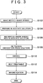
- FIG. 3 is a diagram for describing processes of forming the cathode electrode catalyst layer 32 in the first embodiment of the invention.
- needle-shape bodies of an alloy oxide 34 whose main component is iron are made, and are coated with the carbon coat 36 (S102).
- the making of the alloy oxide 34 and the coating thereof may be accomplished by known methods, and detailed descriptions thereof are omitted herein.
- a Ni-acetate solution is prepared (S104).
- the concentration of the Ni-acetate solution herein is approximately in the range of 0.005 [mol/l] to 10 [mol/l].
- the needle-shape bodies made in step S102 are mixed into the prepared Ni-acetate solution (S 106).
- the amount of the needle-shape bodies for 1 [L] of the Ni-acetate solution is in the range of 5 [g] to 100 [g]. In this step, a state in which Ni ions are adsorbed to the needle-shape bodies is obtained.
- the alloy oxide 34 is magnetized in a gradient magnetic field [dH/dx] of 0.05 [T] or greater.
- the catalyst-supported units formed so that the alloy oxide 34 has magnetism are mixed with the solution 12 containing the same components as the anion exchange membrane 10, and the mixture is applied to the surface of the anion exchange membrane 10.
- the cathode electrode catalyst layer 32 is formed on the surface of the anion exchange membrane 10.
- FIG 4 is a diagram comparing the I-V characteristics of a cell employing a cathode electrode in which the Ni catalyst was supported on a carbon powder and a cell employing a cathode electrode in which the Ni catalyst was supported on a magnetic powder.
- the horizontal axis represents the current density [A/cm 2 ]
- the vertical axis represents the voltage [V].
- the curve plotted with squares represents the fuel cell in accordance with a comparative example
- the curve plotted with solid circles represent the fuel cell in accordance with the first embodiment. From FIG. 4 , it is seen that the fuel cell of the first embodiment was higher in the voltage relative to the current density, and therefore was improved in power generation performance, in comparison with the fuel cell of the comparative example.
- the first embodiment is described above in conjunction with the case where Ni is used for the catalyst particles 38.
- the invention is not limited so. Any other catalyst may also be used as long as it has a necessary function as the catalyst. Concretely, at least one metal selected from the group consisting of iron(Fe), cobalt(Co), nickel (Ni) and platinum(Pt) may be used for the catalyst particles.
- an electrode catalyst may be formed by preparing a Fe-acetate solution, a Co-acetate solution and a Ni-acetate solution instead of the Ni-acetate solution in step S104, and mixing the solutions, and mixing into the mixed solution the needle-shape bodies as a carrier, and then performing the filtration, the heat treatment, etc.
- concentration of each of the Fe-acetate solution, the Ni-acetate solution and the Co-acetate solution may be approximately in the range of 0.05 [mol/l] to 10 [mol/l].
- FIG 5 is a diagram comparing the I-V characteristics of a cell employing a cathode electrode in which the Fe-Co-Ni catalyst was supported on a carbon powder and a cell employing a cathode electrode in which the Fe-Co-Ni catalyst was supported on a magnetic powder.
- the horizontal axis represents the current density [A/cm 2 ]
- the vertical axis represents the voltage [V].
- the curve plotted with squares represents the fuel cell in accordance with a comparative example
- the curve plotted with solid circles represent the fuel cell in accordance with a modification of the first embodiment.
- the anode electrode 20 and the cathode electrode 30 employed the same electrode catalyst, that is, the electrode catalyst in which the catalyst particles of Fe-Co-Ni were supported on the alloy oxide 34 having magnetism.
- the first embodiment is described above in conjunction with the case where the anode electrode 20 and the cathode electrode 30 are constructed of identical electrode catalyst layers.
- the construction of the catalyst layer of the anode electrode 20 does not altogether need to be the same as that of the cathode electrode 30.
- the carriers on which catalysts are supported may also be supports that do not have magnetism.
- Examples of the construction materials of the anode electrode catalyst layer include materials constructed of Fe, CO, Ni, Pt, or the like, materials in which one or more of these metals are supported on carriers made of carbon or the like, organic metal complexes whose center metals are any one or more of these metals, materials in which any of such organic metal complexes is supported on carriers, etc.
- a diffusion layer constructed of a porous material or the like may be disposed on a surface of each electrode catalyst layer.
- the first embodiment uses, as the carrier in the catalyst-supported units in the cathode electrode catalyst layer 32, needle-shape bodies in which the alloy oxide 34 whose main component is iron is coated with the carbon coat 36 and is magnetized.
- the carrier is not limited so.
- any other carrier may also be used as the carrier on which catalysts are supported in the cathode electrode catalyst layer 32 as long as the carrier is able to support the catalyst particles 38, has magnetism and has a needle-like shape having an aspect ratio in the range of 10 to 100.
- the carrier is described above in conjunction with the case where the carrier is a needle-shape body whose aspect ratio is in the range of 10 to 100. The adoption of this shape of the carrier may increase the reaction surface of the catalyst, and therefore may improve the power generation performance.
- the first embodiment is described above in conjunction with the case where the intensity of the gradient magnetic field [dH/dx] for magnetizing the alloy oxide 34 as a carrier is 0.05 [T] or greater.
- the magnetization in a magnetic field whose intensity is within this range is effective in order to effectively attract oxygen in the atmospheric air to the electrode catalyst.
- the magnetic material may also be a material that is magnetized in a gradient magnetic field [dH/dx] of 0.01 [T] or greater.
- the intensity of the magnetic field for the magnetization is not limited to this range, but may also be within an even smaller range.
- the cathode electrode catalyst layer 32 is not limited to the layer formed according to the above-described formation method, but may also be a layer formed by a different method in the invention. Therefore, none of the concentration of the acetic acid solution used in the formation method, the temperature of the heat treatment, etc. limits the invention.
- the first embodiment is described above in conjunction with the case where ethanol is used as a fuel. That is because ethanol is available at a relatively low cost, and allows efficient electric power generation.
- the fuel in the invention is not limited to ethanol.
- the conceivable fuels for use in the case the anion exchange membrane 10 are used as an ion exchange membrane are, for example, methane, ammonia, etc., besides ethanol.
- the fuel cell in the second embodiment has the same structure as the fuel cell of the first embodiment, except that the catalyst particles are different from those used in the fuel cell of the first embodiment.
- the carriers on which catalysts are supported constituting the cathode electrode catalyst layer 32 is a carrier obtained by magnetizing a pulverized oxide of an Fe-Co alloy.
- the mixture ratio of Co in the alloy oxide is appropriately in the range of 5 to 30%.
- the alloy oxide is magnetized in a gradient magnetic field [dH/dx] of 0.05 [T] or greater, and therefore has magnetism. Platinum (Pt) is used for the catalyst particles.
- the magnetism is also able to attract oxygen in the atmospheric air to the cathode electrode 30. Therefore, the concentration overvoltage at the cathode electrode 30 side may be reduced, and the power generation performance of the fuel cell may be effectively improved.
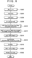
- FIG. 6 is a diagram for describing a formation method for an electrode catalyst of a fuel cell in the second embodiment of the invention.
- the method shown in FIG. 6 has the same processes as the method of FIG 3 , except that the method of FIG. 6 has a process of steps S302 to S314 instead of the process of step S102 to S106 prior to step S108 in FIG. 3 .
- the mixture ratio of Co to the total amount of Fe and Co is approximately in the range of 5 to 30%.
- Fe and Co are melted, and then are cooled (S304, S306). This produces an oxide of an alloy of Fe and Co.
- the produced alloy oxide is pulverized to a size of 1 [ ⁇ m] to 0.1 [ ⁇ m] (S308). In the second embodiment, this pulverized alloy oxide is used as a carrier in the cathode electrode catalyst layer 32.
- step S310 in FIG 6 a platinum chloride aqueous solution is prepared.
- the concentration of the platinum chloride aqueous solution is approximately in the range of 0.005 [mol/l] to 10 [mol/l].
- the alloy oxide formed in step S308 is mixed into the platinum chloride aqueous solution (S312). After that, the mixture liquid is heated. This precipitates Pt, resulting in a state in which Pt is fixed to the alloy oxide.
- FIG. 7 is a diagram for describing the relationships between the current density and the voltage with regard to a fuel cell having a cathode electrode catalyst layer of the second embodiment and a fuel cell of a comparative example.
- FIG 7 is a diagram comparing the I-V characteristics of a cell employing a cathode electrode in which the Pt catalyst was supported on a carbon powder and a cell employing a cathode electrode in which the Pt catalyst was supported on a magnetic powder.
- the horizontal axis represents the current density [A/cm 2 ]
- the vertical axis represents the voltage [V].
- FIG. 7 the horizontal axis represents the current density [A/cm 2 ]
- V the vertical axis represents the voltage [V].
- the curve plotted with squares represents the current density-voltage relationship of the fuel cell of the comparative example
- the curve plotted with solid circles represents the current density-voltage relationship of the fuel cell of the second embodiment. From FIG. 7 , it may be seen that, in the fuel cell of the second embodiment in which Pt is supported on a carrier made of a magnetic alloy oxide, the voltage relative to the current density is higher and the power generation performance is improved in comparison with the fuel cell of the comparative example.
- the catalyst particles in the invention are not limited to particles of Pt, but may also be of Ni, or an Fe-Co-Ni alloy, or the like, as described above in conjunction with the first embodiment.
- the electric power generation reaction is conducted in an alkaline environment. Therefore, even if such a metal as Ni, Fe or the like is used as an electrode catalyst, corrosion of the metal does not occur.
- the use of Ni and Fe allows manufacture of a catalyst at low cost, and therefore allows a cost reduction of the fuel cell, in comparison with the case where Pt is used.
- the use of substantially the same electrode as the anode electrode will achieve the efficient breaking of C-C bonds, and will heighten the fuel utilization rate.
- the power generation performance may be further improved.
- the second embodiment is described above in conjunction with the case where an alloy of Fe and Co is used as a carrier.
- the alloy oxide is not limited so, but may also be a pulverized product of another metal oxide that may be magnetized.
- the oxygen in the supplied reactant gas may be attracted to the electrode catalyst. Therefore, the catalyst function of the electrode catalyst may be heightened.
- the electrode catalyst may be reliably made to have magnetism, and the catalyst function may be heightened.
- the reaction surface of the electrode catalyst may be increased, and therefore the power generation performance may be improved.
- the catalyst particles are particles made of at least one metal of the group consisting of iron, cobalt, nickel and platinum
- the catalyst function of the electrode catalyst may be reliably obtained.
- the use of the catalyst particles of nickel, cobalt or iron may provide an electrode catalyst at a further reduced cost.
- the catalyst particles are particles made of iron, cobalt and nickel, C-C bonds may be more effectively broken. Therefore, even in the case where the catalyst particles are used as the electrode catalyst in the anode electrode side, the reaction on the electrode catalyst may be accelerated, so that the catalyst function may be improved.
- the reaction rate of oxygen in the cathode electrode in particular may be raised, so that a fuel cell with even higher power generation performance may be obtained.
- the electrode catalyst for an alkaline fuel cell is formed by magnetizing the metal oxide after catalyst particles are supported on the metal oxide, an electrode catalyst whose catalyst function is heightened by magnetizing the metal oxide may be obtained.
- the electrode catalyst may be reliably provided with magnetism of a needed intensity, and therefore an electrode catalyst with a high catalyst function may be obtained.
Landscapes
- Chemical & Material Sciences (AREA)
- Chemical Kinetics & Catalysis (AREA)
- Electrochemistry (AREA)
- General Chemical & Material Sciences (AREA)
- Engineering & Computer Science (AREA)
- Materials Engineering (AREA)
- Manufacturing & Machinery (AREA)
- Life Sciences & Earth Sciences (AREA)
- Sustainable Development (AREA)
- Sustainable Energy (AREA)
- Thermal Sciences (AREA)
- Physics & Mathematics (AREA)
- Inert Electrodes (AREA)
- Fuel Cell (AREA)
- Catalysts (AREA)
Abstract
Description
- This invention relates to an electrode catalyst of an alkaline fuel cell and a fuel cell that employs the electrode catalyst as well as a formation method for the alkaline fuel cell electrode catalyst.
- Presently, there are various types of fuel cells, for example, the alkaline type, the phosphoric acid type, the molten carbonate type, the solid electrolyte type, the solid polymer type, etc. As reactant gases used in these fuel cells, for example, pure hydrogen is supplied to the fuel electrode, and atmospheric air is supplied to the oxygen electrode. In some cases, instead of pure hydrogen, a reformed gas obtained by reforming a gas whose main component is hydrogen, such as methane, methanol, etc.
- For example, Japanese Patent No.
3360485 3360485 - When the fuel electrode of the fuel cell is supplied with a fuel, CO contained in the fuel is adsorbed and retained to catalyst particles in the fuel electrode catalyst outer layer. Besides, mainly due to the action of the catalyst particles in the fuel electrode catalyst outer layer, hydrogen in the fuel is separated into protons and electrodes, the electrons are received again on other catalyst particles so as to form a hydrogen gas. The hydrogen gas produced in the fuel electrode catalyst outer layer in this manner passes through the porous base material to reach the fuel electrode catalyst inner layer, in which the hydrogen gas is separated again into electrons and protons. Then, the protons pass through the electrolyte membrane to reach the oxygen electrode.
- That is, in the fuel electrode of Japanese Patent No.
3360485 - In the cathode electrode of the alkaline fuel cell, the oxygen reduction reaction is faster and the overvoltage is lower than in the cathode electrode of the solid polymer fuel cell. However, because the reaction at the cathode electrode side affects the reaction at the anode electrode side, it is preferable to further improve the oxygen reduction reaction. In this respect, Japanese Patent No.
3360485 - This invention provides an electrode catalyst for an alkaline fuel cell which is improved so as to heighten the catalyst function of the cathode electrode, and an alkaline fuel cell that employs the electrode catalyst as well as a formation method for the alkaline fuel cell electrode catalyst.
- An alkaline fuel cell in accordance with a first aspect of the invention is defined in
claim 1. - In the alkaline fuel cell in accordance with the first aspect, the magnetic material may be an oxide of an alloy.
- In the alkaline fuel cell in accordance with the first aspect, the magnetic material may be an oxide of metal that contains iron.
- In the alkaline fuel cell in accordance with the first aspect, the magnetic material may be an oxide of metal that contains iron and cobalt.
- In the alkaline fuel cell in accordance with the first aspect, a mixture ratio of cobalt to a total amount of iron and cobalt in the oxide of metal may be substantially in a range of 5 to 30%.
- In the alkaline fuel cell in accordance with the first aspect, the magnetic material has a narrow long needle-like shape having an aspect ratio in a range of 10 to 100.
- In the alkaline fuel cell in accordance with the first aspect, the magnetic material may be disposed toward the electrode so that a length direction of the magnetic material is perpendicular to the contact surface between an electrolyte membrane and an electrode.
- In the alkaline fuel cell in accordance with the first aspect, the catalyst particles may be particles made up of at least one metal selected from a group consisting of iron, cobalt, nickel and platinum.
- In the alkaline fuel cell in accordance with the first aspect, the catalyst particles may be particles made up of iron, cobalt and nickel.
- In the alalkaline fuel cell in accordance with the first aspect, the catalyst particles may be particles made up of nickel.
- An alkaline fuel cell in accordance with a second aspect of the invention is defined in claim 7.
- In the alkaline fuel cell in accordance with the second aspect, the anode electrode may have the electrode catalyst according to in accordance with the first aspect.
- A formation method for an alkaline fuel cell in accordance with a third aspect of the invention is defined in claim 9 and includes: attaching an ion of a catalyst metal component to a metal oxide by immersing the metal oxide in a solution containing the ion of the catalyst metal component; separating the metal oxide from the solution; heating the metal oxide; and magnetizing the metal oxide after supporting the catalyst metal component on the metal oxide.
- Another formation method for an alkaline fuel cell comprising an electrode catalyst in accordance with the third aspect includes: pulverizing alloy oxide; mixing the pulverized alloy oxide with a solution containing an ion of a catalyst metal component; heating a mixture of the solution and the pulverized alloy oxide; separating the metal oxide from the mixture of the solution and the pulverized alloy oxide; heating the metal oxide; and magnetizing the metal oxide after supporting the catalyst metal component on the metal oxide.
- In the formation method for the alkaline fuel cell in accordance with the third aspect, the metal oxide may contain iron.
- In the formation method for the alkaline fuel cell in accordance with the third aspect, the metal oxide may contain iron and cobalt.
- In the formation method for the alkaline fuel cell in accordance with the third aspect, the magnetic material may have a narrow long needle-like shape having an aspect ratio in a range of 10 to 100.
- In the formation method for the alkaline fuel cell in accordance with the third aspect, the catalyst particles may be particles made up of at least one metal selected from a group consisting of iron, cobalt, nickel and platinum.
- In the formation method for the alkaline fuel cell in accordance with the third aspect, the catalyst particles may be particles made up of iron, cobalt and nickel.
- In the formation method for the alkaline fuel cell in accordance with the third aspect, the solution containing the ion of the catalyst metal component may be obtained by mixing a solution of iron, a solution of cobalt and a solution of nickel whose concentrations are substantially equal.
- In the formation method for the alkaline fuel cell in accordance with the third aspect, the metal oxide may be magnetized in a gradient magnetic field of at least 0.01 [T] or greater.
- In the formation method for the alkaline fuel cell in accordance with the third aspect, the metal oxide may be magnetized in a gradient magnetic field of at least 0.05 [T] or greater.
- According to the first aspect, the alkaline fuel cell is constructed so that the catalyst particles are supported on the magnetic material. Having the magnetism in this manner, the electrode catalyst may attract oxygen in a supplied reactant gas. Therefore, the catalyst function of the electrode catalyst may be heightened.
- In the second aspect, in the case where the electrode catalyst in accordance with the first aspect is used as an electrode catalyst in the cathode electrode side in a fuel cell, the reaction rate of oxygen at the cathode electrode in particular is raised, so that a fuel cell of even higher power generation performance may be obtained.
- In the third aspect, in the case where an electrode catalyst for an alkaline fuel cell is formed by magnetizing a metal oxide after supporting catalyst particles on the metal oxide, an electrode catalyst whose catalyst function has been heightened by magnetizing the metal oxide may be obtained.
- The foregoing and/or further objects, features and advantages of the invention will become more apparent from the following description of preferred embodiment with reference to the accompanying drawings, in which like numerals are used to represent like elements and wherein:
-
FIG. 1 is a schematic diagram for describing a fuel cell in the first embodiment of the invention; -
FIG. 2 is a diagram for describing an electrode catalyst of the fuel cell in the first embodiment of the invention; -
FIG 3 is a diagram for describing manufacture steps of the electrode catalyst of the fuel cell of the first embodiment of the invention; -
FIG 4 is a diagram for describing relationships between the current density and the voltage of a fuel cell of the first embodiment of the invention and a fuel cell of a comparative example; -
FIG 5 is a diagram for describing relationships between the current density and the voltage of another example of the fuel cell of the first embodiment of the invention and a fuel cell of a comparative example; -
FIG 6 is a diagram for describing manufacture steps for an electrode catalyst of a fuel cell in the second embodiment of the invention; and -
FIG 7 is a diagram for describing a relationship between the current density and the voltage of a fuel cell of the second embodiment of the invention. - Hereinafter, embodiments of the invention will be described with reference to the drawings. In addition, the same or corresponding portions are assigned with the same reference numerals, and the description thereof will be simplified or omitted.
-
FIG. 1 is a drawing for describing a construction of a fuel cell of the first embodiment of the invention. The fuel cell shown inFIG 1 is an alkaline fuel cell. The fuel cell has an anion exchange membrane 10 (electrolyte). On two opposite sides of theanion exchange membrane 10, ananode electrode 20 and acathode electrode 30 are disposed. Acurrent collecting plate 40 is disposed on an outer side of each of theanode electrode 20 and thecathode electrode 30. Afuel path 50 is connected to thecurrent collecting plate 40 on theanode electrode 20 side, and a fuel supply sauce (not shown) is connected to thefuel path 50. A fuel is supplied from the fuel supply source to theanode electrode 20 via thefuel path 50 and thecurrent collecting plate 40, so that unreacted fuel or the like is discharged from theanode electrode 20. On the other hand, anoxygen path 60 is connected to the cathode electrode 30-side current collectingplate 40. Via theoxygen path 60 and thecurrent collecting plate 40, atmospheric air is supplied to thecathode electrode 30, so that an atmospheric air off-gas that contains unreacted oxygen is discharged from thecathode electrode 30. - At the time of power generation of the fuel cell, the
anode electrode 20 is supplied with a fuel that contains hydrogen, for example, ethanol or the like. On the other hand, thecathode electrode 30 is supplied with the atmospheric air (or oxygen). As the fuel is supplied to theanode electrode 20, the function of the electrode catalyst layer of theanode electrode 20 causes reaction of hydrogen atoms in the fuel and hydroxide ions that pass through theanion exchange membrane 10 from thecathode electrode 30 side to theanode electrode 20 side, so that water is produced and electrons are released. The reaction at theanode electrode 20 proceeds as in the following equation (1) in the case where the fuel is pure hydrogen or the following equation (2) in the case where the fuel is ethanol.
H2+2OH-→2H2O+2e- (1)
CH3CH2OH+12OH-→2CO2+9H2O+12e- (2)
- On the other hand, as the atmospheric air is supplied to the
cathode electrode 30, the oxygen molecules in the atmospheric air receive electrons from thecathode electrode 30 to produce hydroxide ions through several stages due to the function of the electrode catalyst of thecathode electrode 30 described below. The hydroxide ions move to theanode electrode 20 side through theanion exchange membrane 10. The reaction at thecathode electrode 30 proceeds as in the following equation (3):
1/2O2+H2O+2e-→20H- (3)
- The combination of the reactions at the
anode electrode 20 side and thecathode electrode 30 side described above shows that the water-producing reaction represented by the following equation (4) occurs in the fuel cell as a whole, and the electrons involved in the reaction move via thecurrent collecting plates 40 on the two electrode sides. Therefore, current flows, which means that power generation occurs.
H2+1/2O2→H2O (4)
- In the alkaline-type fuel cell as described above, the
anion exchange membrane 10 is not particularly limited as long as it is a medium capable of moving the hydroxide ions (OH-) produced by the electrode catalyst of thecathode electrode 30 to theanode electrode 20. Concretely, examples of theanion exchange membrane 10 include solid polymer membranes (anion exchange resin) that have anion exchange groups such as primary to tertiary amino groups, quaternary ammonium groups, pyridyl groups, imidazole groups, quaternary pyridium groups, quaternary imidazolium groups, etc. Besides, examples of the solid polymer membrane include membranes of hydrocarbon-based resins, fluorine-based resins, etc. - The
anode electrode 20 has at least an anode electrode catalyst layer. The fuel having passed through thecurrent collecting plate 40 is supplied to the entire surface of the anode electrode catalyst layer. The catalyst layer of theanode electrode 20 has the catalyst function of extracting hydrogen atoms from the supplied fuel and causing the hydrogen atoms to react with hydroxide ions having passed through theanion exchange membrane 10 so as to produce water (H2O) and, at the same time, release electrons (e-) to thecurrent collecting plate 40. In the fuel cell shown inFIG. 1 , theanode electrode 20 has a catalyst layer that is the same as the catalyst layer of thecathode electrode 30 described below. -
FIG. 2 is an enlarged view of a portion of thecathode electrode 30 enclosed by a dotted line (A) inFIG. 1 . As shown inFIG. 2 , thecathode electrode 30 has at least a catalyst layer 32 (electrode catalyst). The atmospheric air supplied via theoxygen path 60 passes through thecurrent collecting plate 40 and is supplied to the entire surface of the cathodeelectrode catalyst layer 32. The cathodeelectrode catalyst layer 32 has a function of receiving electrons (e-) from thecurrent collecting plate 40 and producing hydroxide ions (OH-) from oxygen (O2) and water (H2O). - In order to improve the power generation performance of the fuel cell, it is important that the decomposition of the fuel at the
anode electrode 20 as in the equation (1) or the equation (2) and the production of hydroxide ions (OH-) from oxygen at thecathode electrode 30 as in the equation (3) proceed efficiently. Therefore, it is important to cause a large amount of oxygen to reach the cathodeelectrode catalyst layer 32. In the related-art fuel cell, the movement of oxygen in the atmospheric air supplied to thecathode electrode 30 to thecatalyst layer 32 depends on the concentration diffusion or the like. However, since the oxygen partial pressure in the atmosphere is low, the rate of oxygen reaching thecatalyst layer 32 is slow. This means that the rate of the oxygen reduction reaction from oxygen to hydroxide ions shown in the equation (3) is slow, and the overvoltage becomes large. - In contrast, the fuel cell of the first embodiment adopts the cathode
electrode catalyst layer 32 described below so that more oxygen from the atmospheric air may be attracted to the cathodeelectrode catalyst layer 32 and more hydroxide ions may be efficiently produced. - The cathode
electrode catalyst layer 32 shown inFIG. 2 is formed by applying catalyst-supported units in each which catalyst particles are supported on carriers are applied to theanion exchange membrane 10 with anelectrolyte solution 12 obtained by dissolving substantially the same components as those of theanion exchange membrane 10. Concretely, the carrier (magnetic material/metal oxide) on which catalysts are supported is formed by analloy oxide 34. Thealloy oxide 34 is an oxide of an alloy whose main component is an iron oxide. Besides, the shape of thealloy oxide 34 is a narrow elongated needle shape. Concretely, the aspect ratio of thealloy oxide 34 is in the range of 10 to 100. Furthermore, thealloy oxide 34 is a magnetic material having magnetism which has been magnetized in a magnetic field of 0.05 [T] or greater as a gradient magnetic field [dH/dx]. - The outer surface of the
alloy oxide 34 is coated with acarbon coat 36. Thealloy oxide 34 coated with thecarbon coat 36 supportsmany catalyst particles 38 fixed thereto. Thecatalyst particles 38 are composed of Ni (nickel). - The thus-constructed catalyst-supported units are disposed so that the direction of length of the
alloy oxide 34 is perpendicular to the contact surface between theanion exchange membrane 40 and thecathode electrode 30. It is to be noted herein that the carriers have magnetism. Therefore, due to the magnetism of the catalyst-supported units, the catalyst-supported units may be regularly arranged so that the length direction thereof is perpendicular to theanion exchange membrane 10 when the solution of the catalyst-supported units in theelectrolyte solution 12 is applied to theanion exchange membrane 10. - Incidentally, oxygen has magnetic moment, and has a relatively strong tendency to be magnetically attracted. Therefore, since the
alloy oxide 34 in the cathodeelectrode catalyst layer 32 has magnetism, oxygen in the atmospheric air is attracted by the magnetic force. Therefore, oxygen may be attracted and moved efficiently to the surfaces ofcatalyst particles 38. The oxygen having reached thecatalyst particles 38 adsorbs to the surfaces of thecatalyst particles 38, and is decomposed to produce hydroxide ions as in the foregoing equation (3). Therefore, due to the use of thecatalyst layer 32 in which the catalyst carriers are formed of a magnetic material, a greater amount of oxygen may be attracted to thecatalyst particles 38, so that the production of hydroxide ions will be accelerated and the power generation performance will be improved, even in the case where, for example, a low-current density region lacks oxygen. - On the other hand, the hydroxide ions thus produced do not have a tendency to be magnetically attracted. Therefore, when hydroxide ions are produced from oxygen, the hydroxide ions easily leave the cathode
electrode catalyst layer 32 and move into theanion exchange membrane 10. - Besides, the catalyst-supported units are formed in a needle shape, and are disposed so that the catalyst-supported units are protruded in the length direction thereof from the
anion exchange membrane 10. Therefore, as a whole, the area of the reaction surfaces (three-layer interfaces) in the cathodeelectrode catalyst layer 32 may be increased. This will further raise the oxygen reduction reaction rate in the cathodeelectrode catalyst layer 32, and therefore will heighten the power generation performance. -
FIG. 3 is a diagram for describing processes of forming the cathodeelectrode catalyst layer 32 in the first embodiment of the invention. As shown inFIG. 3 , to form the cathodeelectrode catalyst layer 32, needle-shape bodies of analloy oxide 34 whose main component is iron are made, and are coated with the carbon coat 36 (S102). The making of thealloy oxide 34 and the coating thereof may be accomplished by known methods, and detailed descriptions thereof are omitted herein. - Next, a Ni-acetate solution is prepared (S104). The concentration of the Ni-acetate solution herein is approximately in the range of 0.005 [mol/l] to 10 [mol/l]. The needle-shape bodies made in step S102 are mixed into the prepared Ni-acetate solution (S 106). The amount of the needle-shape bodies for 1 [L] of the Ni-acetate solution is in the range of 5 [g] to 100 [g]. In this step, a state in which Ni ions are adsorbed to the needle-shape bodies is obtained.
- After that, filtration is performed to obtain the alloy oxide from the solution (S108). The filtered alloy oxide is dried (S110). After that, a heat treatment is performed at 300 to 400 [°C] in an inert atmosphere (S112). This results in a state in which Ni is fixed and supported on the carrier (needle-shape bodies).
- Next, magnetization is performed (S114). In this step, the
alloy oxide 34 is magnetized in a gradient magnetic field [dH/dx] of 0.05 [T] or greater. The catalyst-supported units formed so that thealloy oxide 34 has magnetism are mixed with thesolution 12 containing the same components as theanion exchange membrane 10, and the mixture is applied to the surface of theanion exchange membrane 10. As a result, the cathodeelectrode catalyst layer 32 is formed on the surface of theanion exchange membrane 10. -
FIG 4 is a diagram comparing the I-V characteristics of a cell employing a cathode electrode in which the Ni catalyst was supported on a carbon powder and a cell employing a cathode electrode in which the Ni catalyst was supported on a magnetic powder. InFIG 4 , the horizontal axis represents the current density [A/cm2], and the vertical axis represents the voltage [V]. InFIG 4 , the curve plotted with squares represents the fuel cell in accordance with a comparative example, and the curve plotted with solid circles represent the fuel cell in accordance with the first embodiment. FromFIG. 4 , it is seen that the fuel cell of the first embodiment was higher in the voltage relative to the current density, and therefore was improved in power generation performance, in comparison with the fuel cell of the comparative example. - The first embodiment is described above in conjunction with the case where Ni is used for the
catalyst particles 38. However, the invention is not limited so. Any other catalyst may also be used as long as it has a necessary function as the catalyst. Concretely, at least one metal selected from the group consisting of iron(Fe), cobalt(Co), nickel (Ni) and platinum(Pt) may be used for the catalyst particles. - For example, in the case catalyst particles of Fe-Co-Ni are used instead of the
catalyst particles 38 of Ni, an electrode catalyst may be formed by preparing a Fe-acetate solution, a Co-acetate solution and a Ni-acetate solution instead of the Ni-acetate solution in step S104, and mixing the solutions, and mixing into the mixed solution the needle-shape bodies as a carrier, and then performing the filtration, the heat treatment, etc. In addition, the concentration of each of the Fe-acetate solution, the Ni-acetate solution and the Co-acetate solution may be approximately in the range of 0.05 [mol/l] to 10 [mol/l]. -
FIG 5 is a diagram comparing the I-V characteristics of a cell employing a cathode electrode in which the Fe-Co-Ni catalyst was supported on a carbon powder and a cell employing a cathode electrode in which the Fe-Co-Ni catalyst was supported on a magnetic powder. InFIG. 5 , the horizontal axis represents the current density [A/cm2], and the vertical axis represents the voltage [V]. Besides, inFIG. 5 , the curve plotted with squares represents the fuel cell in accordance with a comparative example, and the curve plotted with solid circles represent the fuel cell in accordance with a modification of the first embodiment. In addition, in these examples, too, theanode electrode 20 and thecathode electrode 30 employed the same electrode catalyst, that is, the electrode catalyst in which the catalyst particles of Fe-Co-Ni were supported on thealloy oxide 34 having magnetism. - From
FIG 5 , it may be seen that, in the case where catalyst particles of Fe-Co-Ni were supported on thealloy oxide 34 having magnetism, the voltage relative to the current density was higher and the power generation performance was improved, in comparison with the case where the catalyst particles of Fe-Co-Ni were supported merely on carbon powder. - Furthermore, it may be understood that, in the case where the catalyst particles of Fe-Co-Ni were employed, higher catalyst-performance was exhibited than in the case where the catalyst particles of Ni were employed. A reason for this is considered to be that, in the case where the catalyst particles of Fe-Co-Ni were employed, the catalyst particles of Fe-Co-Ni in the
anode electrode 20 have the effect of breaking C-C bonds. That is, it is considered that in the case where theanode electrode 20 side is supplied with ethanol as a fuel, the C-C bonds of the fuel are efficiently broken in the fuel electrode side, so that hydrogen ions may be quickly produced from the fuel. - Furthermore, the first embodiment is described above in conjunction with the case where the
anode electrode 20 and thecathode electrode 30 are constructed of identical electrode catalyst layers. However, in the invention, the construction of the catalyst layer of theanode electrode 20 does not altogether need to be the same as that of thecathode electrode 30. For example, in the catalyst layer of theanode electrode 20, the carriers on which catalysts are supported may also be supports that do not have magnetism. Examples of the construction materials of the anode electrode catalyst layer include materials constructed of Fe, CO, Ni, Pt, or the like, materials in which one or more of these metals are supported on carriers made of carbon or the like, organic metal complexes whose center metals are any one or more of these metals, materials in which any of such organic metal complexes is supported on carriers, etc. Besides, a diffusion layer constructed of a porous material or the like may be disposed on a surface of each electrode catalyst layer. - Besides, the first embodiment uses, as the carrier in the catalyst-supported units in the cathode
electrode catalyst layer 32, needle-shape bodies in which thealloy oxide 34 whose main component is iron is coated with thecarbon coat 36 and is magnetized. However, in the invention, the carrier is not limited so. In the invention, any other carrier may also be used as the carrier on which catalysts are supported in the cathodeelectrode catalyst layer 32 as long as the carrier is able to support thecatalyst particles 38, has magnetism and has a needle-like shape having an aspect ratio in the range of 10 to 100. The carrier is described above in conjunction with the case where the carrier is a needle-shape body whose aspect ratio is in the range of 10 to 100. The adoption of this shape of the carrier may increase the reaction surface of the catalyst, and therefore may improve the power generation performance. - Furthermore, the first embodiment is described above in conjunction with the case where the intensity of the gradient magnetic field [dH/dx] for magnetizing the
alloy oxide 34 as a carrier is 0.05 [T] or greater. The magnetization in a magnetic field whose intensity is within this range is effective in order to effectively attract oxygen in the atmospheric air to the electrode catalyst. However, the invention is not limited so. Concretely, the magnetic material may also be a material that is magnetized in a gradient magnetic field [dH/dx] of 0.01 [T] or greater. The intensity of the magnetic field for the magnetization is not limited to this range, but may also be within an even smaller range. - Furthermore, although the first embodiment is described above in conjunction with an example of the formation method for the cathode
electrode catalyst layer 32, the cathodeelectrode catalyst layer 32 is not limited to the layer formed according to the above-described formation method, but may also be a layer formed by a different method in the invention. Therefore, none of the concentration of the acetic acid solution used in the formation method, the temperature of the heat treatment, etc. limits the invention. - Furthermore, the first embodiment is described above in conjunction with the case where ethanol is used as a fuel. That is because ethanol is available at a relatively low cost, and allows efficient electric power generation. However, the fuel in the invention is not limited to ethanol. As described above in conjunction with the first embodiment, the conceivable fuels for use in the case the
anion exchange membrane 10 are used as an ion exchange membrane are, for example, methane, ammonia, etc., besides ethanol. - The fuel cell in the second embodiment has the same structure as the fuel cell of the first embodiment, except that the catalyst particles are different from those used in the fuel cell of the first embodiment. Concretely, in the fuel cell of the second embodiment, the carriers on which catalysts are supported constituting the cathode
electrode catalyst layer 32 is a carrier obtained by magnetizing a pulverized oxide of an Fe-Co alloy. The mixture ratio of Co in the alloy oxide is appropriately in the range of 5 to 30%. As in the first embodiment, the alloy oxide is magnetized in a gradient magnetic field [dH/dx] of 0.05 [T] or greater, and therefore has magnetism. Platinum (Pt) is used for the catalyst particles. - Even in the case where an oxide of a Fe-Co alloy is magnetized, the magnetism is also able to attract oxygen in the atmospheric air to the
cathode electrode 30. Therefore, the concentration overvoltage at thecathode electrode 30 side may be reduced, and the power generation performance of the fuel cell may be effectively improved. -
FIG. 6 is a diagram for describing a formation method for an electrode catalyst of a fuel cell in the second embodiment of the invention. The method shown inFIG. 6 has the same processes as the method ofFIG 3 , except that the method ofFIG. 6 has a process of steps S302 to S314 instead of the process of step S102 to S106 prior to step S108 inFIG. 3 . - Concretely, in the method shown in
FIG 6 , firstly Fe and Co are mixed (S302). In this step, the mixture ratio of Co to the total amount of Fe and Co is approximately in the range of 5 to 30%. Next, Fe and Co are melted, and then are cooled (S304, S306). This produces an oxide of an alloy of Fe and Co. Next, the produced alloy oxide is pulverized to a size of 1 [µm] to 0.1 [µm] (S308). In the second embodiment, this pulverized alloy oxide is used as a carrier in the cathodeelectrode catalyst layer 32. - In step S310 in
FIG 6 , a platinum chloride aqueous solution is prepared. The concentration of the platinum chloride aqueous solution is approximately in the range of 0.005 [mol/l] to 10 [mol/l]. The alloy oxide formed in step S308 is mixed into the platinum chloride aqueous solution (S312). After that, the mixture liquid is heated. This precipitates Pt, resulting in a state in which Pt is fixed to the alloy oxide. - After that, filtration, desiccation and heat treatment are performed as in steps S108 to S114 in
FIG. 3 (S316 to S322). This results in formation of catalyst-supported units in which catalyst particles of Pt are supported on the alloy oxide. After that, the alloy oxide of the catalyst-supported units is magnetized (S322). The catalyst-supported units formed as described above are mixed into a solution containing the same components as theanion exchange membrane 10, and the mixture is applied to the surface of theanion exchange membrane 10. Thus, a cathode electrode catalyst layer is formed. -
FIG. 7 is a diagram for describing the relationships between the current density and the voltage with regard to a fuel cell having a cathode electrode catalyst layer of the second embodiment and a fuel cell of a comparative example.FIG 7 is a diagram comparing the I-V characteristics of a cell employing a cathode electrode in which the Pt catalyst was supported on a carbon powder and a cell employing a cathode electrode in which the Pt catalyst was supported on a magnetic powder. InFIG. 7 , the horizontal axis represents the current density [A/cm2] , and the vertical axis represents the voltage [V]. Besides, inFIG. 7 , the curve plotted with squares represents the current density-voltage relationship of the fuel cell of the comparative example, and the curve plotted with solid circles represents the current density-voltage relationship of the fuel cell of the second embodiment. FromFIG. 7 , it may be seen that, in the fuel cell of the second embodiment in which Pt is supported on a carrier made of a magnetic alloy oxide, the voltage relative to the current density is higher and the power generation performance is improved in comparison with the fuel cell of the comparative example. - The second embodiment is described above in conjunction with the case where catalyst particles of Pt are supported. However, the catalyst particles in the invention are not limited to particles of Pt, but may also be of Ni, or an Fe-Co-Ni alloy, or the like, as described above in conjunction with the first embodiment. In the fuel cell in the invention, the electric power generation reaction is conducted in an alkaline environment. Therefore, even if such a metal as Ni, Fe or the like is used as an electrode catalyst, corrosion of the metal does not occur. Furthermore, the use of Ni and Fe allows manufacture of a catalyst at low cost, and therefore allows a cost reduction of the fuel cell, in comparison with the case where Pt is used.
- Furthermore, in the second embodiment, in the case where a Fe-Co-Ni alloy is used for the catalyst particles, the use of substantially the same electrode as the anode electrode will achieve the efficient breaking of C-C bonds, and will heighten the fuel utilization rate. Thus, the power generation performance may be further improved.
- Furthermore, the second embodiment is described above in conjunction with the case where an alloy of Fe and Co is used as a carrier. However, the alloy oxide is not limited so, but may also be a pulverized product of another metal oxide that may be magnetized.
- According to the invention, due to the magnetization, the oxygen in the supplied reactant gas may be attracted to the electrode catalyst. Therefore, the catalyst function of the electrode catalyst may be heightened.
- Furthermore, in the case where the magnetic material is a metal oxide containing iron or a metal oxide containing iron and cobalt, the electrode catalyst may be reliably made to have magnetism, and the catalyst function may be heightened.
- Furthermore, in the case where the magnetic material has a needle-shape body whose aspect ratio is in the range of 10 to 100, the reaction surface of the electrode catalyst may be increased, and therefore the power generation performance may be improved.
- Furthermore, in the case where the catalyst particles are particles made of at least one metal of the group consisting of iron, cobalt, nickel and platinum, the catalyst function of the electrode catalyst may be reliably obtained. Besides, the use of the catalyst particles of nickel, cobalt or iron may provide an electrode catalyst at a further reduced cost.
- Furthermore, in the case where the catalyst particles are particles made of iron, cobalt and nickel, C-C bonds may be more effectively broken. Therefore, even in the case where the catalyst particles are used as the electrode catalyst in the anode electrode side, the reaction on the electrode catalyst may be accelerated, so that the catalyst function may be improved.
- In the case where the electrode catalyst in accordance with the invention is used as the electrode catalyst in the cathode electrode side, the reaction rate of oxygen in the cathode electrode in particular may be raised, so that a fuel cell with even higher power generation performance may be obtained.
- Furthermore, in the case where the electrode catalyst for an alkaline fuel cell is formed by magnetizing the metal oxide after catalyst particles are supported on the metal oxide, an electrode catalyst whose catalyst function is heightened by magnetizing the metal oxide may be obtained.
- Furthermore, in the case where the metal oxide is magnetized in a gradient magnetic field of 0.01 [T] or greater or of 0.05 [T] or greater, the electrode catalyst may be reliably provided with magnetism of a needed intensity, and therefore an electrode catalyst with a high catalyst function may be obtained.
- If in the embodiment of the invention, numerical values regarding the number of pieces or the like, the quantity, the amount, the range, etc., of any of the component elements of the foregoing embodiments or the like are referred to, the numerical values are not restrictive, except for the case where a numerical value is particularly explicitly presented, or is specifically determined with theoretical clearness. Besides, the structures, the steps in the method, etc., described with the embodiments are not necessarily essential to the invention, except for the case where a structure, a step, or the like is particularly explicitly presented, or is specifically determined with theoretical clearness.
Claims (15)
- An alkaline fuel cell comprising an electrode catalyst (32) for an alkaline fuel cell, comprising:a magnetic material (34) provided as a carrier that has magnetism; andcatalyst particles (38) supported on the magnetic material (34),wherein the magnetic material (34) has a narrow long needle-like shape having an aspect ratio in a range of 10 to 100.
- The alkaline fuel cell according to claim 1, wherein the magnetic material (34) is an oxide of an alloy, or
wherein the magnetic material (34) is an oxide of metal that contains iron. - The alkaline fuel cell according to claim 1 or 2,
wherein the magnetic material (34) is an oxide of metal that contains iron and cobalt, and
wherein, optionally, a mixture ratio of cobalt to a total amount of iron and cobalt in the oxide of metal is in a range of 5 to 30%. - The alkaline fuel cell according to any one of claims 1 to 3, wherein the magnetic material (34) is disposed toward the electrode so that a length direction of the magnetic material (34) is perpendicular to the contact surface between an electrolyte (10) and an electrode.
- The alkaline fuel cell according to any one of claims 1 to 4, wherein the catalyst particles (38) are particles made up of at least one metal selected from a group consisting of iron, cobalt, nickel and platinum.
- The alkaline fuel cell according to claim 5, wherein the catalyst particles (38) are particles made up of iron, cobalt and nickel, or
wherein the catalyst particles (38) are particles made up of nickel. - The alkaline fuel cell according to any of claims 1 to 6 further comprising:an electrolyte (10) through which a negative ion is allowed to permeate;an anode electrode (20) disposed on one side of the electrolyte (10); anda cathode electrode (30) disposed on the other side of the electrolyte (10),
wherein the electrode catalyst (32) is used in the cathode electrode (30). - The alkaline fuel cell according to claim 7, wherein the the electrode catalyst (32) is used in the anode electrode (20).
- A formation method for the alkaline fuel cell comprising an electrode catalyst (32) according to any one of claims 1 to 6, comprising:attaching an ion of a catalyst metal component to a metal oxide by immersing the metal oxide in a solution containing the ion of the catalyst metal component;separating the metal oxide from the solution;heating the metal oxide; andmagnetizing the metal oxide after supporting the catalyst metal component on the metal oxide.
- A formation method for the alkaline fuel cell comprising an electrode catalyst (32) according to any one of claims 1 to 6, comprising:pulverizing alloy oxide;mixing the pulverized alloy oxide with a solution
containing an ion of a catalyst metal component;heating a mixture of the solution and the pulverized alloy oxide;separating the metal oxide from the mixture of the solution and the pulverized alloy oxide;heating the metal oxide; andmagnetizing the metal oxide after supporting the catalyst metal component on the metal oxide. - The formation method according to claim 9 or 10,
wherein the metal oxide contains iron, and/or
wherein the metal oxide contains iron and cobalt, and/or
wherein the metal oxide has a narrow long needle-like shape having an aspect ratio in a range of 10 to 100. - The formation method according to any one of claims 9 to 11, wherein catalyst particles (38) are particles made up of at least one metal selected from a group consisting of iron, cobalt, nickel and platinum.
- The formation method according to claim 12, wherein the catalyst particles (38) are particles made up of iron, cobalt and nickel, and
wherein, optionally, the solution containing the ion of the catalyst metal component is obtained by mixing a solution of iron, a solution of cobalt and a solution of nickel whose concentrations are equal. - The formation method according to any one of claims 9 to 13, wherein the metal oxide is magnetized in a gradient magnetic field of at least 0.01 [T] or greater.
- The formation method according to claim 14, wherein the metal oxide is magnetized in a gradient magnetic field of at least 0.05 [T] or greater.
Applications Claiming Priority (2)
| Application Number | Priority Date | Filing Date | Title |
|---|---|---|---|
| JP2007133002A JP5119738B2 (en) | 2007-05-18 | 2007-05-18 | Electrode catalyst for alkaline fuel cell, alkaline fuel cell, and method for forming electrode catalyst for alkaline fuel cell |
| PCT/IB2008/001211 WO2008142515A1 (en) | 2007-05-18 | 2008-05-15 | Electrode catalyst for alkaline fuel cell, alkaline fuel cell, and formation method for alkaline fuel cell electrode catalyst |
Publications (2)
| Publication Number | Publication Date |
|---|---|
| EP2153482A1 EP2153482A1 (en) | 2010-02-17 |
| EP2153482B1 true EP2153482B1 (en) | 2012-04-25 |
Family
ID=39708322
Family Applications (1)
| Application Number | Title | Priority Date | Filing Date |
|---|---|---|---|
| EP08750952A Not-in-force EP2153482B1 (en) | 2007-05-18 | 2008-05-15 | Electrode catalyst for alkaline fuel cell, alkaline fuel cell, and formation method for alkaline fuel cell electrode catalyst |
Country Status (6)
| Country | Link |
|---|---|
| US (2) | US20100159365A1 (en) |
| EP (1) | EP2153482B1 (en) |
| JP (1) | JP5119738B2 (en) |
| CN (1) | CN101682034B (en) |
| AT (1) | ATE555508T1 (en) |
| WO (1) | WO2008142515A1 (en) |
Families Citing this family (10)
| Publication number | Priority date | Publication date | Assignee | Title |
|---|---|---|---|---|
| US10279328B2 (en) | 2009-02-27 | 2019-05-07 | Basf Corporation | Process for the preparation of metal-carbon containing bodies |
| EP2233207A1 (en) * | 2009-02-27 | 2010-09-29 | Basf Se | Process for the preparation of metal-carbon containing bodies |
| US9642192B2 (en) * | 2011-08-04 | 2017-05-02 | Fuelcell Energy, Inc. | Method and manufacturing assembly for sintering fuel cell electrodes and impregnating porous electrodes with electrolyte powders by induction heating for mass production |
| US20140378016A1 (en) | 2012-03-29 | 2014-12-25 | University Of Iowa Research Foundation | Magnetically modified metals and metal alloys for hydride storage |
| CN102769140A (en) * | 2012-07-30 | 2012-11-07 | 大连交通大学 | A method for preparing an ordered catalytic layer of an electrode of a proton exchange membrane fuel cell |
| CN106898782A (en) * | 2015-12-21 | 2017-06-27 | 中国科学院大连化学物理研究所 | A kind of preparation of fuel cell electrode and the device of electrode is prepared using the method |
| CN109921042B (en) * | 2017-12-13 | 2022-02-22 | 中国科学院大连化学物理研究所 | Metal array catalyst layer of anion exchange membrane fuel cell and preparation method thereof |
| CN112397737B (en) * | 2021-01-20 | 2021-04-13 | 北京科技大学 | Electric pile device of platinum-based magnetic field regulation fuel cell and manufacturing method thereof |
| CN114974665B (en) * | 2022-05-17 | 2025-09-02 | 昆明理工大学 | A solid waste-based multilayer electrode and its application |
| CN115020721A (en) * | 2022-07-12 | 2022-09-06 | 一汽解放汽车有限公司 | Membrane electrode catalytic slurry, membrane electrode, preparation method of membrane electrode and fuel cell |
Family Cites Families (29)
| Publication number | Priority date | Publication date | Assignee | Title |
|---|---|---|---|---|
| US3811952A (en) * | 1970-10-08 | 1974-05-21 | Powercell Ab S T | Method and apparatus for supplying entirely or substantially entirely consumable metallic material to a magnetic electrode in a metal/oxygen or metal/air cell |
| US4541925A (en) * | 1982-09-22 | 1985-09-17 | Exxon Research And Engineering Co. | Composition and hydrotreating process for the operation of a magnetically stabilized fluidized bed |
| US7709115B2 (en) * | 1994-08-25 | 2010-05-04 | University Of Iowa Research Foundation | Methods for forming magnetically modified electrodes and articles produced thereby |
| US20050213187A1 (en) * | 1994-08-25 | 2005-09-29 | University Of Iowa Research Foundation | Methods for forming magnetically modified electrodes and articles produced thereby |
| US6355166B1 (en) * | 1994-08-25 | 2002-03-12 | The University Of Iowa Research Foundation | Magnetically enhanced composite materials and methods for making and using the same |
| US5871625A (en) * | 1994-08-25 | 1999-02-16 | University Of Iowa Research Foundation | Magnetic composites for improved electrolysis |
| JPH09315801A (en) * | 1996-03-26 | 1997-12-09 | Toyota Motor Corp | Fuel reforming method, fuel reforming apparatus, and fuel cell system including the fuel reforming apparatus |
| WO2001028025A1 (en) * | 1999-10-14 | 2001-04-19 | University Of Iowa Research Foundation | Magnetically modified fuel cells |
| JP2002198057A (en) * | 2000-05-23 | 2002-07-12 | National Institute Of Advanced Industrial & Technology | Fuel cell and improved oxygen electrode for use therein |
| CN100347208C (en) | 2001-09-27 | 2007-11-07 | Jsr株式会社 | Conjugated diene homo-or copolymer rubber, method for producing homo-or copolymer rubber, rubber composition, composite, and tire |
| US7288594B2 (en) | 2001-12-03 | 2007-10-30 | Bridgestone Corporation | Process for producing modified polymer modified polymer obtained by the process and rubber composition |
| EP1505087B1 (en) | 2002-04-12 | 2007-07-11 | Bridgestone Corporation | Process for producing modified polymer, modified polymer obtained by the process, and rubber composition |
| WO2004052547A2 (en) * | 2002-12-05 | 2004-06-24 | Surfect Technologies, Inc. | Coated and magnetic particles and applications thereof |
| KR100506091B1 (en) * | 2003-02-19 | 2005-08-04 | 삼성에스디아이 주식회사 | Catalyst for cathode of fuel cell |
| JP2005149742A (en) * | 2003-11-11 | 2005-06-09 | Nissan Motor Co Ltd | Catalyst supporting electrode for fuel cell and method for producing the same |
| FR2863777B1 (en) * | 2003-12-16 | 2006-02-17 | Commissariat Energie Atomique | ALKALINE FUEL CELL INSENSITIVE TO CARBONATION. |
| US7749935B2 (en) * | 2004-01-27 | 2010-07-06 | Showa Denko K.K. | Catalyst carrier and fuel cell using the same |
| JP2005264214A (en) * | 2004-03-17 | 2005-09-29 | Tokyo Institute Of Technology | Magnetic hollow material and manufacturing method thereof |
| JP2005294109A (en) * | 2004-04-01 | 2005-10-20 | Toyota Motor Corp | FUEL CELL SUBSTRATE AND FUEL CELL |
| JP4729865B2 (en) * | 2004-04-27 | 2011-07-20 | 株式会社エクォス・リサーチ | How to use the fuel cell |
| JP2005346929A (en) * | 2004-05-31 | 2005-12-15 | Equos Research Co Ltd | Membrane electrode assembly of direct fuel cell, system and method of using the system |
| US20100291415A1 (en) * | 2004-07-15 | 2010-11-18 | Johna Leddy | Methods for increasing carbon monoxide tolerance in fuel cells |
| JP2006252966A (en) * | 2005-03-10 | 2006-09-21 | Nissan Motor Co Ltd | ELECTRODE CATALYST LAYER FOR FUEL CELL AND FUEL CELL USING THE SAME |
| US8247136B2 (en) * | 2005-03-15 | 2012-08-21 | The Regents Of The University Of California | Carbon based electrocatalysts for fuel cells |
| JP4197683B2 (en) * | 2005-03-15 | 2008-12-17 | 株式会社東芝 | Catalyst for fuel cell electrode, fuel cell electrode, membrane electrode assembly, and fuel cell |
| US7767330B2 (en) * | 2005-05-04 | 2010-08-03 | Gm Global Technology Operations, Inc. | Conductive matrices for fuel cell electrodes |
| JP2007319735A (en) * | 2006-05-30 | 2007-12-13 | Fuji Xerox Co Ltd | Microreactor and method for cleaning micro flow path |
| US7763374B2 (en) * | 2006-11-22 | 2010-07-27 | Atomic Energy Council | Membrane fuel cell electrodes incorporated with carbon nanomaterial-supported electrocatalysts and methods of making the same |
| US20080206616A1 (en) * | 2007-02-27 | 2008-08-28 | Cabot Corporation | Catalyst coated membranes and sprayable inks and processes for forming same |
-
2007
- 2007-05-18 JP JP2007133002A patent/JP5119738B2/en not_active Expired - Fee Related
-
2008
- 2008-05-15 AT AT08750952T patent/ATE555508T1/en active
- 2008-05-15 EP EP08750952A patent/EP2153482B1/en not_active Not-in-force
- 2008-05-15 US US12/600,624 patent/US20100159365A1/en not_active Abandoned
- 2008-05-15 CN CN2008800164593A patent/CN101682034B/en not_active Expired - Fee Related
- 2008-05-15 WO PCT/IB2008/001211 patent/WO2008142515A1/en not_active Ceased
-
2014
- 2014-05-15 US US14/277,931 patent/US20140248441A1/en not_active Abandoned
Also Published As
| Publication number | Publication date |
|---|---|
| ATE555508T1 (en) | 2012-05-15 |
| EP2153482A1 (en) | 2010-02-17 |
| WO2008142515A1 (en) | 2008-11-27 |
| JP5119738B2 (en) | 2013-01-16 |
| JP2008288084A (en) | 2008-11-27 |
| US20100159365A1 (en) | 2010-06-24 |
| US20140248441A1 (en) | 2014-09-04 |
| CN101682034A (en) | 2010-03-24 |
| CN101682034B (en) | 2013-04-10 |
Similar Documents
| Publication | Publication Date | Title |
|---|---|---|
| EP2153482B1 (en) | Electrode catalyst for alkaline fuel cell, alkaline fuel cell, and formation method for alkaline fuel cell electrode catalyst | |
| Park et al. | Commercial anion exchange membrane water electrolyzer stack through non-precious metal electrocatalysts | |
| JP4083721B2 (en) | High concentration carbon supported catalyst, method for producing the same, catalyst electrode using the catalyst, and fuel cell using the same | |
| US7566514B2 (en) | Catalyst for cathode in fuel cell | |
| AU2009246798B2 (en) | Permselective membrane-free direct fuel cell and components thereof | |
| EP2166604B1 (en) | Electrode catalyst, method for producing the same, and solid polymer fuel cell | |
| Li et al. | Platinum-tellurium alloy metallene toward formic acid oxidation reaction | |
| US9634331B2 (en) | Non-PGM cathode catalysts for fuel cell application derived from heat treated heteroatomic amines precursors | |
| Zheng et al. | Mimicking hydrazine dehydrogenase for efficient electrocatalytic oxidation of N2H4 by Fe–NC | |
| Chen et al. | Ultrastable and highly efficient hydrogen evolution by heterogeneous NiO/Ni catalysts under industrial electrolysis conditions | |
| CN112886024A (en) | Preparation method of myrica cobalt nickel boron composite carbon material proton membrane fuel cell catalyst | |
| EP2156492B1 (en) | Alkaline fuel cell electrode catalyst, alkaline fuel cell, manufacture method for alkaline fuel cell electrode catalyst, and manufacture method for alkaline fuel cell | |
| JP2005294109A (en) | FUEL CELL SUBSTRATE AND FUEL CELL | |
| US9608276B2 (en) | Nanostructured PtxMy catalyst for PEMFC cells having a high activity and a moderate H2O2 production | |
| Ding et al. | Non‐Metallic Element Modification: A Promising Strategy Toward Efficient Electrocatalytic CO2 Reduction | |
| KR20050103648A (en) | Catalist for fuel cell, preparation method thereof, and fuel cell system comprising the same | |
| JP2005251455A (en) | Catalyst for fuel cell and production method thereof, electrode, and direct methanol fuel cell | |
| Liu | Atomic layer deposition of electrocatalysts for use in fuel cells and electrolyzers | |
| US20230349057A1 (en) | Hydrogen evolution reaction catalysts, electrodes and electrolyzers based thereon and methods of fabrication thereof | |
| KR102691210B1 (en) | Method for manufacturing electrodes and electrodes for fuel cells | |
| CN120272926A (en) | Method for producing hydrogen by using platinum-based alloy catalyst | |
| HK1113331B (en) | Hydrogen absorption induced metal deposition on palladium and palladium-alloy particles | |
| HK1113331A1 (en) | Hydrogen absorption induced metal deposition on palladium and palladium-alloy particles |
Legal Events
| Date | Code | Title | Description |
|---|---|---|---|
| PUAI | Public reference made under article 153(3) epc to a published international application that has entered the european phase |
Free format text: ORIGINAL CODE: 0009012 |
|
| 17P | Request for examination filed |
Effective date: 20091117 |
|
| AK | Designated contracting states |
Kind code of ref document: A1 Designated state(s): AT BE BG CH CY CZ DE DK EE ES FI FR GB GR HR HU IE IS IT LI LT LU LV MC MT NL NO PL PT RO SE SI SK TR |
|
| AX | Request for extension of the european patent |
Extension state: AL BA MK RS |
|
| DAX | Request for extension of the european patent (deleted) | ||
| 17Q | First examination report despatched |
Effective date: 20110905 |
|
| GRAP | Despatch of communication of intention to grant a patent |
Free format text: ORIGINAL CODE: EPIDOSNIGR1 |
|
| GRAS | Grant fee paid |
Free format text: ORIGINAL CODE: EPIDOSNIGR3 |
|
| GRAA | (expected) grant |
Free format text: ORIGINAL CODE: 0009210 |
|
| AK | Designated contracting states |
Kind code of ref document: B1 Designated state(s): AT BE BG CH CY CZ DE DK EE ES FI FR GB GR HR HU IE IS IT LI LT LU LV MC MT NL NO PL PT RO SE SI SK TR |
|
| REG | Reference to a national code |
Ref country code: GB Ref legal event code: FG4D |
|
| REG | Reference to a national code |
Ref country code: CH Ref legal event code: EP |
|
| REG | Reference to a national code |
Ref country code: AT Ref legal event code: REF Ref document number: 555508 Country of ref document: AT Kind code of ref document: T Effective date: 20120515 |
|
| REG | Reference to a national code |
Ref country code: IE Ref legal event code: FG4D |
|
| REG | Reference to a national code |
Ref country code: DE Ref legal event code: R096 Ref document number: 602008015203 Country of ref document: DE Effective date: 20120621 |
|
| REG | Reference to a national code |
Ref country code: NL Ref legal event code: VDEP Effective date: 20120425 |
|
| REG | Reference to a national code |
Ref country code: AT Ref legal event code: MK05 Ref document number: 555508 Country of ref document: AT Kind code of ref document: T Effective date: 20120425 |
|
| LTIE | Lt: invalidation of european patent or patent extension |
Effective date: 20120425 |
|
| PG25 | Lapsed in a contracting state [announced via postgrant information from national office to epo] |
Ref country code: FI Free format text: LAPSE BECAUSE OF FAILURE TO SUBMIT A TRANSLATION OF THE DESCRIPTION OR TO PAY THE FEE WITHIN THE PRESCRIBED TIME-LIMIT Effective date: 20120425 Ref country code: NO Free format text: LAPSE BECAUSE OF FAILURE TO SUBMIT A TRANSLATION OF THE DESCRIPTION OR TO PAY THE FEE WITHIN THE PRESCRIBED TIME-LIMIT Effective date: 20120725 Ref country code: IS Free format text: LAPSE BECAUSE OF FAILURE TO SUBMIT A TRANSLATION OF THE DESCRIPTION OR TO PAY THE FEE WITHIN THE PRESCRIBED TIME-LIMIT Effective date: 20120825 Ref country code: PL Free format text: LAPSE BECAUSE OF FAILURE TO SUBMIT A TRANSLATION OF THE DESCRIPTION OR TO PAY THE FEE WITHIN THE PRESCRIBED TIME-LIMIT Effective date: 20120425 Ref country code: SE Free format text: LAPSE BECAUSE OF FAILURE TO SUBMIT A TRANSLATION OF THE DESCRIPTION OR TO PAY THE FEE WITHIN THE PRESCRIBED TIME-LIMIT Effective date: 20120425 Ref country code: LT Free format text: LAPSE BECAUSE OF FAILURE TO SUBMIT A TRANSLATION OF THE DESCRIPTION OR TO PAY THE FEE WITHIN THE PRESCRIBED TIME-LIMIT Effective date: 20120425 Ref country code: CY Free format text: LAPSE BECAUSE OF FAILURE TO SUBMIT A TRANSLATION OF THE DESCRIPTION OR TO PAY THE FEE WITHIN THE PRESCRIBED TIME-LIMIT Effective date: 20120425 |
|
| PG25 | Lapsed in a contracting state [announced via postgrant information from national office to epo] |
Ref country code: HR Free format text: LAPSE BECAUSE OF FAILURE TO SUBMIT A TRANSLATION OF THE DESCRIPTION OR TO PAY THE FEE WITHIN THE PRESCRIBED TIME-LIMIT Effective date: 20120425 Ref country code: GR Free format text: LAPSE BECAUSE OF FAILURE TO SUBMIT A TRANSLATION OF THE DESCRIPTION OR TO PAY THE FEE WITHIN THE PRESCRIBED TIME-LIMIT Effective date: 20120726 Ref country code: LV Free format text: LAPSE BECAUSE OF FAILURE TO SUBMIT A TRANSLATION OF THE DESCRIPTION OR TO PAY THE FEE WITHIN THE PRESCRIBED TIME-LIMIT Effective date: 20120425 Ref country code: SI Free format text: LAPSE BECAUSE OF FAILURE TO SUBMIT A TRANSLATION OF THE DESCRIPTION OR TO PAY THE FEE WITHIN THE PRESCRIBED TIME-LIMIT Effective date: 20120425 Ref country code: PT Free format text: LAPSE BECAUSE OF FAILURE TO SUBMIT A TRANSLATION OF THE DESCRIPTION OR TO PAY THE FEE WITHIN THE PRESCRIBED TIME-LIMIT Effective date: 20120827 |
|
| PG25 | Lapsed in a contracting state [announced via postgrant information from national office to epo] |
Ref country code: MC Free format text: LAPSE BECAUSE OF NON-PAYMENT OF DUE FEES Effective date: 20120531 Ref country code: BE Free format text: LAPSE BECAUSE OF FAILURE TO SUBMIT A TRANSLATION OF THE DESCRIPTION OR TO PAY THE FEE WITHIN THE PRESCRIBED TIME-LIMIT Effective date: 20120425 |
|
| REG | Reference to a national code |
Ref country code: CH Ref legal event code: PL |
|
| PG25 | Lapsed in a contracting state [announced via postgrant information from national office to epo] |
Ref country code: RO Free format text: LAPSE BECAUSE OF FAILURE TO SUBMIT A TRANSLATION OF THE DESCRIPTION OR TO PAY THE FEE WITHIN THE PRESCRIBED TIME-LIMIT Effective date: 20120425 Ref country code: CZ Free format text: LAPSE BECAUSE OF FAILURE TO SUBMIT A TRANSLATION OF THE DESCRIPTION OR TO PAY THE FEE WITHIN THE PRESCRIBED TIME-LIMIT Effective date: 20120425 Ref country code: EE Free format text: LAPSE BECAUSE OF FAILURE TO SUBMIT A TRANSLATION OF THE DESCRIPTION OR TO PAY THE FEE WITHIN THE PRESCRIBED TIME-LIMIT Effective date: 20120425 Ref country code: SK Free format text: LAPSE BECAUSE OF FAILURE TO SUBMIT A TRANSLATION OF THE DESCRIPTION OR TO PAY THE FEE WITHIN THE PRESCRIBED TIME-LIMIT Effective date: 20120425 Ref country code: DK Free format text: LAPSE BECAUSE OF FAILURE TO SUBMIT A TRANSLATION OF THE DESCRIPTION OR TO PAY THE FEE WITHIN THE PRESCRIBED TIME-LIMIT Effective date: 20120425 Ref country code: CH Free format text: LAPSE BECAUSE OF NON-PAYMENT OF DUE FEES Effective date: 20120531 Ref country code: AT Free format text: LAPSE BECAUSE OF FAILURE TO SUBMIT A TRANSLATION OF THE DESCRIPTION OR TO PAY THE FEE WITHIN THE PRESCRIBED TIME-LIMIT Effective date: 20120425 Ref country code: LI Free format text: LAPSE BECAUSE OF NON-PAYMENT OF DUE FEES Effective date: 20120531 Ref country code: NL Free format text: LAPSE BECAUSE OF FAILURE TO SUBMIT A TRANSLATION OF THE DESCRIPTION OR TO PAY THE FEE WITHIN THE PRESCRIBED TIME-LIMIT Effective date: 20120425 |
|
| RAP2 | Party data changed (patent owner data changed or rights of a patent transferred) |
Owner name: TOYOTA JIDOSHA KABUSHIKI KAISHA |
|
| REG | Reference to a national code |
Ref country code: IE Ref legal event code: MM4A |
|
| PG25 | Lapsed in a contracting state [announced via postgrant information from national office to epo] |
Ref country code: IT Free format text: LAPSE BECAUSE OF FAILURE TO SUBMIT A TRANSLATION OF THE DESCRIPTION OR TO PAY THE FEE WITHIN THE PRESCRIBED TIME-LIMIT Effective date: 20120425 |
|
| PLBE | No opposition filed within time limit |
Free format text: ORIGINAL CODE: 0009261 |
|
| REG | Reference to a national code |
Ref country code: FR Ref legal event code: ST Effective date: 20130131 |
|
| STAA | Information on the status of an ep patent application or granted ep patent |
Free format text: STATUS: NO OPPOSITION FILED WITHIN TIME LIMIT |
|
| REG | Reference to a national code |
Ref country code: GB Ref legal event code: 746 Effective date: 20130215 |
|
| 26N | No opposition filed |
Effective date: 20130128 |
|
| PG25 | Lapsed in a contracting state [announced via postgrant information from national office to epo] |
Ref country code: ES Free format text: LAPSE BECAUSE OF FAILURE TO SUBMIT A TRANSLATION OF THE DESCRIPTION OR TO PAY THE FEE WITHIN THE PRESCRIBED TIME-LIMIT Effective date: 20120805 Ref country code: IE Free format text: LAPSE BECAUSE OF NON-PAYMENT OF DUE FEES Effective date: 20120515 Ref country code: FR Free format text: LAPSE BECAUSE OF NON-PAYMENT OF DUE FEES Effective date: 20120625 |
|
| REG | Reference to a national code |
Ref country code: DE Ref legal event code: R084 Ref document number: 602008015203 Country of ref document: DE Effective date: 20130312 |
|
| REG | Reference to a national code |
Ref country code: DE Ref legal event code: R097 Ref document number: 602008015203 Country of ref document: DE Effective date: 20130128 |
|
| PG25 | Lapsed in a contracting state [announced via postgrant information from national office to epo] |
Ref country code: MT Free format text: LAPSE BECAUSE OF FAILURE TO SUBMIT A TRANSLATION OF THE DESCRIPTION OR TO PAY THE FEE WITHIN THE PRESCRIBED TIME-LIMIT Effective date: 20120425 Ref country code: BG Free format text: LAPSE BECAUSE OF FAILURE TO SUBMIT A TRANSLATION OF THE DESCRIPTION OR TO PAY THE FEE WITHIN THE PRESCRIBED TIME-LIMIT Effective date: 20120725 |
|
| PG25 | Lapsed in a contracting state [announced via postgrant information from national office to epo] |
Ref country code: TR Free format text: LAPSE BECAUSE OF FAILURE TO SUBMIT A TRANSLATION OF THE DESCRIPTION OR TO PAY THE FEE WITHIN THE PRESCRIBED TIME-LIMIT Effective date: 20120425 |
|
| PG25 | Lapsed in a contracting state [announced via postgrant information from national office to epo] |
Ref country code: LU Free format text: LAPSE BECAUSE OF NON-PAYMENT OF DUE FEES Effective date: 20120515 |
|
| PG25 | Lapsed in a contracting state [announced via postgrant information from national office to epo] |
Ref country code: HU Free format text: LAPSE BECAUSE OF FAILURE TO SUBMIT A TRANSLATION OF THE DESCRIPTION OR TO PAY THE FEE WITHIN THE PRESCRIBED TIME-LIMIT Effective date: 20080515 |
|
| PGFP | Annual fee paid to national office [announced via postgrant information from national office to epo] |
Ref country code: DE Payment date: 20170509 Year of fee payment: 10 Ref country code: GB Payment date: 20170510 Year of fee payment: 10 |
|
| REG | Reference to a national code |
Ref country code: DE Ref legal event code: R119 Ref document number: 602008015203 Country of ref document: DE |
|
| GBPC | Gb: european patent ceased through non-payment of renewal fee |
Effective date: 20180515 |
|
| PG25 | Lapsed in a contracting state [announced via postgrant information from national office to epo] |
Ref country code: GB Free format text: LAPSE BECAUSE OF NON-PAYMENT OF DUE FEES Effective date: 20180515 Ref country code: DE Free format text: LAPSE BECAUSE OF NON-PAYMENT OF DUE FEES Effective date: 20181201 |