EP2153100B1 - Grommet - Google Patents
Grommet Download PDFInfo
- Publication number
- EP2153100B1 EP2153100B1 EP08737205.8A EP08737205A EP2153100B1 EP 2153100 B1 EP2153100 B1 EP 2153100B1 EP 08737205 A EP08737205 A EP 08737205A EP 2153100 B1 EP2153100 B1 EP 2153100B1
- Authority
- EP
- European Patent Office
- Prior art keywords
- grommet
- aperture
- lip portion
- component
- wall portion
- Prior art date
- Legal status (The legal status is an assumption and is not a legal conclusion. Google has not performed a legal analysis and makes no representation as to the accuracy of the status listed.)
- Active
Links
Images

Classifications
-
- F—MECHANICAL ENGINEERING; LIGHTING; HEATING; WEAPONS; BLASTING
- F16—ENGINEERING ELEMENTS AND UNITS; GENERAL MEASURES FOR PRODUCING AND MAINTAINING EFFECTIVE FUNCTIONING OF MACHINES OR INSTALLATIONS; THERMAL INSULATION IN GENERAL
- F16L—PIPES; JOINTS OR FITTINGS FOR PIPES; SUPPORTS FOR PIPES, CABLES OR PROTECTIVE TUBING; MEANS FOR THERMAL INSULATION IN GENERAL
- F16L5/00—Devices for use where pipes, cables or protective tubing pass through walls or partitions
- F16L5/02—Sealing
- F16L5/027—Sealing by means of a joint of the quick-acting type
Definitions
- the present invention relates to a grommet for use in locating and protecting the surface of articles such as electrical cables and pipes passing through apertures in the face or web of a component.
- grommets especially for aerospace use have been quite complex with regard to time and effort required to fit them and are consequently costly.
- it is first necessary to select the appropriate grommet material for the component aperture in question; cut the grommet material to length to surround the circumference of the aperture; apply adhesive to the grommet material/component aperture surfaces; install the grommet material around the aperture and cure the adhesive.
- some form of article restraint such a "P" clip or the like is required and which necessitates drilling holes in the component and riveting, bolting or otherwise securing the clip/restraint in place.
- the document FR2841960 discloses a known grommet.
- a further object of the grommet of the present invention is to accommodate a range of thicknesses of material with which it may be employed.
- a grommet for use with a component for protecting the surface of cables or pipes passing an aperture extending through a wall of said component, said grommet comprising:
- the resilient fingers cooperate with the flange portion to resist disengagement.
- the cylindrical wall portion has a main diameter substantially corresponding to a diameter of the aperture in which it is to be inserted.
- said main wall portion is a sliding fit that does not require excessive force to insert.
- the axially directed resilient fingers may be formed directly from the wall portion by providing axially directed slots therein so as to permit the fingers to deform radially inwardly during initial insertion of the grommet into the aperture.
- the slots are preferably of a width that is less than the diameter of any one of the articles passing through the grommet, so as to prevent such article from being inserted in or entering said slots with the consequent potential damage that might result from the article being trapped or snagged in the said slots when being fed through the grommet, for example, or from fretting damage when installed.
- a further reason for the slots being smaller than the diameter or width of any article passing through the grommet is to prevent the articles from coming into contact either during installation or when installed with the probable sharp edge of the aperture in which the grommet is installed and thus preventing any possible damage due to abrasion or fretting.
- slots there are six axially directed slots forming three resilient fingers wherein the slots may extend, when the grommet is installed in the aperture, all the way "through" the thickness of the component and the depth of any flange portion which may be present around the aperture.
- the number of axially directed fingers may vary according to the diameter or size of the grommet.
- a grommet intended to be inserted in a hole of about 20mm diameter may have six axially directed slots forming three plain skirt panels and three fingers having means for resisting disengagement as described below.
- the circumferential length of the plain skirt panels and the fixing fingers may be different. Whilst the fingers having means to prevent disengagement are important, the plain skirt panels are also important and desirably should extend in an axial direction at least beyond the edge of the aperture in which the grommet is installed so as to prevent the articles passing through the grommet from coming into contact with the edge of the aperture.
- the circumferential width of the plain skirt panels is a result of the number of resilient fingers having means to resist disengagement which is a more important design consideration so as to ensure that the grommet is firmly anchored in the component aperture, the circumferential width per se of the plain skirt panels being of lesser importance other than that they protect the articles from the aperture edge.
- the means for resisting disengagement of the grommet from the component may be any that is suitable.
- the means comprise wedge-shaped barb portions formed on the ends of at least some of the axially directed fingers.
- the barb portions have a minimum thickness at the end of the grommet, which provide a lead into the aperture and an increasing thickness along an axial length thereof.
- the resilient fingers possessing the barbs deform radially inwardly until the barb portions are fully inserted and the thickest part exits the aperture and the resilient fingers having the barb portions spring radially outwardly to engage the face of the component or the end of a flange portion if present.
- an axially inwardly face of the means for resisting disengagement of the grommet has a form such that an axially directed force to remove the grommet does not result in the resilient fingers being moved radially inwardly.
- the outwardly extending lip portion is inclined relative to the axis of the generally cylindrical wall portion and in an axially inwardly direction such that the outer circumference of the lip portion provides an annular contact portion with the component surface that it contacts.
- the outwardly extending lip portion may preferably be resilient.
- the resilience of the downwardly inclined lip portion provides axial resilience in the grommet as a whole thus enabling the grommet to seat securely without undue axial play either in a range of different material thicknesses or accommodate a greater tolerance band of depth dimensions of a formed flange portion around the component aperture or both.
- the degree of resilience in the lip portion of the grommet may be controlled and adjusted by several means including the provision of stiffness reducing slots or holes therein; varying the thickness of the material forming a radial wall of the lip portion relative to the cylindrical wall portion; and, varying the thickness of the material constituting the lip portion along the radial length thereof.
- the distance between the annular contact portion of the lip portion and the axially inner face of the barb portion may be slightly less than the thickness of the material or the depth of the flanged aperture into which the grommet is to be inserted so as to avoid unwanted axial play.
- the grommet of the present invention there may be provided a radial slit through the whole grommet at one wall position thus, the grommet is still in a single piece but may be opened out or made smaller in circumferential size.
- the purpose of the radial slit is to provide a means whereby the grommet may easily be removed from the component aperture and replaced, without having to remove or displace the articles passing through the aperture.
- the grommet may be provided with means to restrain an article passing through the grommet when installed in the aperture.
- Such means may comprise at least one generally axially directed restraining member and may preferably be formed at one axial end of the grommet.
- the at least one restraining member may be formed as part of one or more of the axially directed resilient fingers, but preferably, the at least one restraining member may be provided at the end of the grommet having the lip portion and be associated with the wall portion and/or the lip portion as it is believed that this arrangement provides more stiffness to the restraining member.
- the at least one restraining member may be a solid post-like member but having means thereon to co-operate with a tie of some form to anchor the article passing through the grommet thereto without the tie slipping off.
- Such means may comprise, for example, a lip, a protrusion, a saw-tooth form along an edge of the member or any other suitable means.
- a restraining member comprising a closed aperture.
- Such a closed aperture may take any suitable form and in one embodiment of the present invention the closed aperture comprises two or more generally parallel post-like members which may be parallel to the grommet axis and joined together at their ends remote from the point where the restraining member is joined to the grommet itself.
- a space between the two generally parallel post-like members provides positive location and anchorage for a conventional cable tie to pass through the gap between the two post portions.
- the closed aperture may be in the form of a loop such as a generally circular loop, for example.
- a cable-tie or tube-tie band may be formed integrally with the at least one restraining member of the grommet.
- the grommet according to the present invention is made of a plastics material of a suitable type and the grommet moulded therefrom.
- a grommet according to the present invention is indicated generally at 10 and comprises a generally cylindrical wall portion 12; a lip member 14 formed at one end of the grommet; and, a restraining member 16.
- the wall portion 12 and lip 14 has a radially directed slit 18 passing through the grommet in the axial direction thus making the grommet circumferentially discontinuous.
- the wall portion 12 is divided up in its lower region by axially directed slots 20 which effectively render the lower region of the wall portion into a plurality of resilient finger portions comprising skirt panels 22 and resilient fingers 24 which are also provided with retention means 26 (described below) to permit easy insertion of the grommet 10 into a hole 28 having a flange 30 in a sheet structural member indicated in part at 32 (whilst this embodiment is described with reference to a grommet 10 being installed in a component or part 32 having an aperture or hole 28 having a flange 30, it is stressed that it is not necessary that the aperture 28 has a flange 30, the principles and structural features described applying equally to a grommet 10 being installed in a component having a plain hole 28 having no flange).
- the retention means 26 comprise generally wedge-shaped barb portions 34.
- the barb portions in the present embodiment have a first sloping face 36 which provide the wall portion with an effective diameter at the leading edge 38 of the barb portions slightly less than that of the hole 28 into which the grommet is to be inserted.
- the barb portions have a second sloping face portion 40 having a smaller angle of inclination to the grommet axis 42 than the first sloping face 36 (it should be noted that in other embodiments the face portions 36, 40 may be integrated into a common, single face having a single angle of inclination).
- a locking face portion 44 which is substantially normal to the axis 42 and which, when the grommet 10 is fully inserted in the hole 28, engages said hole 28, in the current embodiment with an end face 46 of the hole flange 30.
- the lip member 14 extends in a downwardly and outwardly direction from the end of the wall portion 12 to which it is joined.
- the lip member 14 is resilient and forms in effect an axial spring to ensure that barb locking face portions 44 are securely seated on the edge of the component aperture due to the resilient force exerted by the lip member 14 by virtue of the deformation thereof on insertion into the component aperture. As may be seen in Fig.
- the wall 50 is, in this embodiment, of substantially constant thickness, and therefore, acts as a disc spring.
- the resilience of the lip member may be changed in different grommet embodiments by changing the thickness of the lip member wall 50 and/or providing window portions 52 and/or changing the angle of the wall 50 of lip member 14 relative to the cylindrical wall 12 and which parameters may be used to alter the overall strength and/or resiliency of the lip member wall 50.
- the lip member 14 has an outer circumferential edge 54 which engages the surface 56 of the structural member 32.
- a restraining or anchor member 16 for fixing a cable, bundle of cables and/or tubes or pipes (all not shown) passing through the central aperture 62 of the grommet.
- the anchor member comprises two post members 64, 66 which are generally parallel to the axis 42, the post members being joined at their ends by a bridging piece 68 to form a closed slot 70.
- a conventional cable tie, indicated in part only at 72 may be passed through the slot 70 to encircle the cable etc. and fix the same to the anchor member 16 to prevent radial and/or axial movement relative to the grommet.
- the restraining member 16 may have different forms such as, for example, a single post or a non-closed slot or other arrangements as described herein above.
- the vertical distance "h” between the outer circumferential edge 54 of the flange and the barb face locking face 44 is, in the free state of the grommet, slightly less than the overall depth or thickness of the component, more specifically of hole flange 30.
- the lip member wall 50 is resiliently deformed so that the structural member 32 is firmly gripped by the grommet 10.
- the distance "h” will vary from application to application to accommodate the range of thicknesses of component with which the grommet may be employed.
- the axially directed slots 20 extend in the axial direction to an extent that they are at least coterminous with or extend slightly beyond the surface 56 of the structural member 32 on which the flange peripheral edge 54 bears in order to allow some radially inwardly flexibility of the finger portions 22, 24 to be accommodated in a hole which may have a greater degree of interference with the grommet than which would normally be desired.
- the facing edges of the radial slit 18 may be displaced relative to each other by forcing one face radially inwardly and the grommet removed whilst still leaving any cables or tubes passing through the aperture in place.
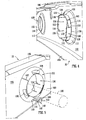
- Figures 4 and 5 show a perspective view of an embodiment of a grommet according to the present invention which is substantially the same as that described with reference to Figures 1 to 3 .
- Figure 4 shows part of a component 32 in the form of a fuselage frame 100 made from sheet metal and having a generally radially extending face 102 and stiffening webs 104, 106 extending generally axially. Holes 108 are provided in the frame both for weight reduction purposes and for routing cabling and the like therethrough.
- One hole 108 on the left as viewed in Figure 4 is not fitted with a grommet whilst the right hand hole 108 is so fitted with a grommet 110.
- the grommet-free hole 108 is provide with a a stiffening flange 112 which is angled at other than 90° to the face 102, unlike the flange 30 shown in Figure 3 .
- the holes 108 may be plain holes having no flange and the presence or otherwise of a flange will depend upon the structural requirements of the component in question.
- the flange 112 has an edge 114 defining the flange aperture opening and which provides an abutment face for barb portions of grommet resilient fingers described below.
- the grommet 110 shown installed in the right hand hole of Figure 4 has three resilient fingers 120 and three skirt panels 122 mutually separated by slots 124.
- the resilient fingers 120 are provided with wedge portions 126, in this case having a single angled sloping face 128 rather than the twin-angled sloping faces 36, 40 shown in the embodiment of Figures 1 to 3 .
- Each wedge portion 126 has a locking face 130 which engages the edge 114 of the flange 112 to prevent unwanted disengagement of the grommet 110.
- the locking face 130 may be substantially parallel to the frame face 102.
- Figure 5 shows the front face of the frame 100 of Figure 4 .
- the grommet 110 has a lip member 132 which is angled to the main wall portion 134 and has apertures 136 to aid in controlling the stiffness thereof as well as its weight.
- the lip member 132 has an outer circumferential seating edge 140 which abuts the front of face 102 whilst the lip member 132 is resiliently deformed in an axial direction so as to provide an axially directed resilient force retaining the grommet in the hole 108.
- the lip member 132 has a radially directed slit 142 to aid removal if required.
- the grommet 110 is provided with an integrally formed restraining member 146 comprising two axially oriented posts 148, 150 with a closure bar 152 connecting them to form an aperture 154 to receive an anchoring member such as a cable tie (not shown).
- a cable bundle 160 denoted by dashed lines is shown passing through the grommet 110 and which is anchored to the restraining member 146 with a suitable tie.
Landscapes
- Engineering & Computer Science (AREA)
- General Engineering & Computer Science (AREA)
- Mechanical Engineering (AREA)
- Insulating Bodies (AREA)
- Installation Of Indoor Wiring (AREA)
Description
- The present invention relates to a grommet for use in locating and protecting the surface of articles such as electrical cables and pipes passing through apertures in the face or web of a component.
- Large structures such as aeroplanes, for example, utilise large quantities of relatively thin materials especially in internal structure such a fuselage frames, wing ribs and the like. It is frequently necessary to make or utilize existing apertures in such components to enable electrical cables and tubes, for example, to pass therethrough. The aperture itself is either cut, machined or punched and is often provided with a flange portion around the periphery of the aperture. Whether or not there is a flange portion, the remaining edge of the cut or punched portion of the aperture is often sharp and abrasive to items such as those described above which are required to pass through the aperture.
- In addition to the need for cables and the like to merely pass through the aperture, it is also desirable to restrain unwanted movement of the article in the region of the aperture, generally both in the radial (with respect to the grommet/aperture) and longitudinal (with respect to the article) directions.
- Known grommets, especially for aerospace use have been quite complex with regard to time and effort required to fit them and are consequently costly. In one type of grommet, it is first necessary to select the appropriate grommet material for the component aperture in question; cut the grommet material to length to surround the circumference of the aperture; apply adhesive to the grommet material/component aperture surfaces; install the grommet material around the aperture and cure the adhesive. In addition to this some form of article restraint such a "P" clip or the like is required and which necessitates drilling holes in the component and riveting, bolting or otherwise securing the clip/restraint in place.
- The document
FR2841960 - It is an object of the present invention to provide a grommet which is quick and easy to install yet secure and provide for restraint of the article or articles passing therethrough. A further object of the grommet of the present invention is to accommodate a range of thicknesses of material with which it may be employed.
- According to the present invention there is provided a grommet for use with a component for protecting the surface of cables or pipes passing an aperture extending through a wall of said component, said grommet comprising:
- a cylindrical main wall portion;
- a lip portion connected to and extending outwardly and annularly from an axial end of the main wall portion, wherein said lip portion is resiliently deformable to provide an axial spring for resisting disengagement of said grommet from said aperture in said component; and
- wherein said main wall portion defines
a plurality of resilient fingers, at least some of said fingers having barb portions for resisting disengagement of said grommet from said aperture in said component; - characterised in that said main wall portion further defines a plurality of skirt panels;
- wherein the plurality of the resilient fingers and skirt panels extend axially from the lip portion,
- wherein said plurality of resilient fingers and skirt panels are separated from one another by axially directed slots in the main wall portion;
- wherein said lip portion cooperates with the barb portions to exert an axial compressive force on opposing surfaces of said component;
- Other optional features are detailed in the appended dependent claims.
- In one embodiment of the present invention, the resilient fingers cooperate with the flange portion to resist disengagement.
- In one embodiment of the present invention the cylindrical wall portion has a main diameter substantially corresponding to a diameter of the aperture in which it is to be inserted. In a further refinement of this embodiment, said main wall portion is a sliding fit that does not require excessive force to insert.
- The axially directed resilient fingers may be formed directly from the wall portion by providing axially directed slots therein so as to permit the fingers to deform radially inwardly during initial insertion of the grommet into the aperture. The slots are preferably of a width that is less than the diameter of any one of the articles passing through the grommet, so as to prevent such article from being inserted in or entering said slots with the consequent potential damage that might result from the article being trapped or snagged in the said slots when being fed through the grommet, for example, or from fretting damage when installed. A further reason for the slots being smaller than the diameter or width of any article passing through the grommet is to prevent the articles from coming into contact either during installation or when installed with the probable sharp edge of the aperture in which the grommet is installed and thus preventing any possible damage due to abrasion or fretting.
- In one embodiment, for example, there are six axially directed slots forming three resilient fingers wherein the slots may extend, when the grommet is installed in the aperture, all the way "through" the thickness of the component and the depth of any flange portion which may be present around the aperture.
- The number of axially directed fingers may vary according to the diameter or size of the grommet. For example, a grommet intended to be inserted in a hole of about 20mm diameter may have six axially directed slots forming three plain skirt panels and three fingers having means for resisting disengagement as described below. The circumferential length of the plain skirt panels and the fixing fingers may be different. Whilst the fingers having means to prevent disengagement are important, the plain skirt panels are also important and desirably should extend in an axial direction at least beyond the edge of the aperture in which the grommet is installed so as to prevent the articles passing through the grommet from coming into contact with the edge of the aperture. However, the circumferential width of the plain skirt panels is a result of the number of resilient fingers having means to resist disengagement which is a more important design consideration so as to ensure that the grommet is firmly anchored in the component aperture, the circumferential width per se of the plain skirt panels being of lesser importance other than that they protect the articles from the aperture edge.
- The means for resisting disengagement of the grommet from the component may be any that is suitable. In one embodiment the means comprise wedge-shaped barb portions formed on the ends of at least some of the axially directed fingers. The barb portions have a minimum thickness at the end of the grommet, which provide a lead into the aperture and an increasing thickness along an axial length thereof. As the grommet is inserted into the aperture, the resilient fingers possessing the barbs deform radially inwardly until the barb portions are fully inserted and the thickest part exits the aperture and the resilient fingers having the barb portions spring radially outwardly to engage the face of the component or the end of a flange portion if present. Preferably, an axially inwardly face of the means for resisting disengagement of the grommet has a form such that an axially directed force to remove the grommet does not result in the resilient fingers being moved radially inwardly.
- In a preferred embodiment, the outwardly extending lip portion is inclined relative to the axis of the generally cylindrical wall portion and in an axially inwardly direction such that the outer circumference of the lip portion provides an annular contact portion with the component surface that it contacts. Furthermore, the outwardly extending lip portion may preferably be resilient. Thus, the resilience of the downwardly inclined lip portion provides axial resilience in the grommet as a whole thus enabling the grommet to seat securely without undue axial play either in a range of different material thicknesses or accommodate a greater tolerance band of depth dimensions of a formed flange portion around the component aperture or both.
- The degree of resilience in the lip portion of the grommet may be controlled and adjusted by several means including the provision of stiffness reducing slots or holes therein; varying the thickness of the material forming a radial wall of the lip portion relative to the cylindrical wall portion; and, varying the thickness of the material constituting the lip portion along the radial length thereof.
- In its free state, the distance between the annular contact portion of the lip portion and the axially inner face of the barb portion, for example, may be slightly less than the thickness of the material or the depth of the flanged aperture into which the grommet is to be inserted so as to avoid unwanted axial play.
- In a preferred embodiment of the grommet of the present invention there may be provided a radial slit through the whole grommet at one wall position thus, the grommet is still in a single piece but may be opened out or made smaller in circumferential size. The purpose of the radial slit is to provide a means whereby the grommet may easily be removed from the component aperture and replaced, without having to remove or displace the articles passing through the aperture.
- In a further preferred embodiment, the grommet may be provided with means to restrain an article passing through the grommet when installed in the aperture. Such means may comprise at least one generally axially directed restraining member and may preferably be formed at one axial end of the grommet. The at least one restraining member may be formed as part of one or more of the axially directed resilient fingers, but preferably, the at least one restraining member may be provided at the end of the grommet having the lip portion and be associated with the wall portion and/or the lip portion as it is believed that this arrangement provides more stiffness to the restraining member.
- The at least one restraining member may be a solid post-like member but having means thereon to co-operate with a tie of some form to anchor the article passing through the grommet thereto without the tie slipping off. Such means may comprise, for example, a lip, a protrusion, a saw-tooth form along an edge of the member or any other suitable means. However in a preferred embodiment of the restraining member, there may be provided a restraining member comprising a closed aperture. Such a closed aperture may take any suitable form and in one embodiment of the present invention the closed aperture comprises two or more generally parallel post-like members which may be parallel to the grommet axis and joined together at their ends remote from the point where the restraining member is joined to the grommet itself. A space between the two generally parallel post-like members provides positive location and anchorage for a conventional cable tie to pass through the gap between the two post portions.
In another embodiment of the present invention, the closed aperture may be in the form of a loop such as a generally circular loop, for example. - In a further modified embodiment of the grommet according to the present invention a cable-tie or tube-tie band may be formed integrally with the at least one restraining member of the grommet.
- Preferably, the grommet according to the present invention is made of a plastics material of a suitable type and the grommet moulded therefrom.
- In order that the present invention may be more fully understood, an example will now be described by way of illustration only with reference to the accompanying drawings, of which:
-
Figure 1 shows a plan view of a preferred embodiment of a grommet according to the present invention; -
Figure 2 show a view in elevation of the grommet ofFigure 1 ; -
Figure 3 which shows a cross section along the line 3 - 3 ofFigure 2 ; -
Figure 4 shows an isometric view of the rear of part of a component having two holes therein, one of which is fitted with a grommet according to the present invention; and -
Figure 5 which shows an isometric view of the front of the component ofFigure 4 of the hole having the fitted grommet. - Referring now to the drawings and where the same features are denoted by common reference numerals.
- A grommet according to the present invention is indicated generally at 10 and comprises a generally
cylindrical wall portion 12; alip member 14 formed at one end of the grommet; and, a restrainingmember 16. Thewall portion 12 andlip 14 has a radially directed slit 18 passing through the grommet in the axial direction thus making the grommet circumferentially discontinuous. Thewall portion 12 is divided up in its lower region by axially directedslots 20 which effectively render the lower region of the wall portion into a plurality of resilient finger portions comprisingskirt panels 22 andresilient fingers 24 which are also provided with retention means 26 (described below) to permit easy insertion of thegrommet 10 into ahole 28 having aflange 30 in a sheet structural member indicated in part at 32 (whilst this embodiment is described with reference to agrommet 10 being installed in a component orpart 32 having an aperture orhole 28 having aflange 30, it is stressed that it is not necessary that theaperture 28 has aflange 30, the principles and structural features described applying equally to agrommet 10 being installed in a component having aplain hole 28 having no flange). The retention means 26 comprise generally wedge-shapedbarb portions 34. In this example there are three circumferentiallynarrower finger portions 24 and three circumferentiallylonger skirt panels 22 but this may vary according to, for example, the diameter of the grommet (i.e. the number and size of fingers/skirt panels may vary). The barb portions in the present embodiment have a firstsloping face 36 which provide the wall portion with an effective diameter at theleading edge 38 of the barb portions slightly less than that of thehole 28 into which the grommet is to be inserted. The barb portions have a secondsloping face portion 40 having a smaller angle of inclination to thegrommet axis 42 than the first sloping face 36 (it should be noted that in other embodiments theface portions barb portions 34 there is a lockingface portion 44 which is substantially normal to theaxis 42 and which, when thegrommet 10 is fully inserted in thehole 28, engages saidhole 28, in the current embodiment with anend face 46 of thehole flange 30. Since both the barb lockingface portions 44 and theflange end face 46 are both substantially parallel to each other there is no tendency for the two faces to move relative to each other in a radial direction and thus, there is no tendency for the grommet to inadvertently become disengaged from thehole 28. Thelip member 14 extends in a downwardly and outwardly direction from the end of thewall portion 12 to which it is joined. Thelip member 14 is resilient and forms in effect an axial spring to ensure that barb lockingface portions 44 are securely seated on the edge of the component aperture due to the resilient force exerted by thelip member 14 by virtue of the deformation thereof on insertion into the component aperture. As may be seen inFig. 3 thewall 50 is, in this embodiment, of substantially constant thickness, and therefore, acts as a disc spring. The resilience of the lip member may be changed in different grommet embodiments by changing the thickness of thelip member wall 50 and/or providingwindow portions 52 and/or changing the angle of thewall 50 oflip member 14 relative to thecylindrical wall 12 and which parameters may be used to alter the overall strength and/or resiliency of thelip member wall 50. Thelip member 14 has an outercircumferential edge 54 which engages the surface 56 of thestructural member 32. At the lip end of the grommet there is further provided a restraining oranchor member 16 for fixing a cable, bundle of cables and/or tubes or pipes (all not shown) passing through thecentral aperture 62 of the grommet. The anchor member comprises twopost members axis 42, the post members being joined at their ends by abridging piece 68 to form aclosed slot 70. A conventional cable tie, indicated in part only at 72 may be passed through theslot 70 to encircle the cable etc. and fix the same to theanchor member 16 to prevent radial and/or axial movement relative to the grommet. In other embodiments the restrainingmember 16 may have different forms such as, for example, a single post or a non-closed slot or other arrangements as described herein above. - The vertical distance "h" between the outer
circumferential edge 54 of the flange and the barbface locking face 44 is, in the free state of the grommet, slightly less than the overall depth or thickness of the component, more specifically ofhole flange 30. Thus, when the grommet is pressed fully into engagement in thehole 28 such that theedge 54 is in contact with the surface 56 of thestructural member 32 and the two faces 44, 46 are engaged, thelip member wall 50 is resiliently deformed so that thestructural member 32 is firmly gripped by thegrommet 10. Of course, the distance "h" will vary from application to application to accommodate the range of thicknesses of component with which the grommet may be employed. - The axially directed
slots 20 extend in the axial direction to an extent that they are at least coterminous with or extend slightly beyond the surface 56 of thestructural member 32 on which the flangeperipheral edge 54 bears in order to allow some radially inwardly flexibility of thefinger portions - In order to remove the grommet from the hole the facing edges of the radial slit 18 may be displaced relative to each other by forcing one face radially inwardly and the grommet removed whilst still leaving any cables or tubes passing through the aperture in place.
-
Figures 4 and 5 show a perspective view of an embodiment of a grommet according to the present invention which is substantially the same as that described with reference toFigures 1 to 3 .Figure 4 shows part of acomponent 32 in the form of afuselage frame 100 made from sheet metal and having a generally radially extendingface 102 and stiffeningwebs Holes 108 are provided in the frame both for weight reduction purposes and for routing cabling and the like therethrough. Onehole 108 on the left as viewed inFigure 4 is not fitted with a grommet whilst theright hand hole 108 is so fitted with agrommet 110. As may be seen inFigure 4 the grommet-free hole 108 is provide with a a stiffeningflange 112 which is angled at other than 90° to theface 102, unlike theflange 30 shown inFigure 3 . However, it is repeated that theholes 108 may be plain holes having no flange and the presence or otherwise of a flange will depend upon the structural requirements of the component in question. Theflange 112 has anedge 114 defining the flange aperture opening and which provides an abutment face for barb portions of grommet resilient fingers described below. Thegrommet 110 shown installed in the right hand hole ofFigure 4 has threeresilient fingers 120 and threeskirt panels 122 mutually separated byslots 124. Theresilient fingers 120 are provided withwedge portions 126, in this case having a single angled slopingface 128 rather than the twin-angled sloping faces 36, 40 shown in the embodiment ofFigures 1 to 3 . Eachwedge portion 126 has a lockingface 130 which engages theedge 114 of theflange 112 to prevent unwanted disengagement of thegrommet 110. Ideally the lockingface 130 may be substantially parallel to theframe face 102.Figure 5 shows the front face of theframe 100 ofFigure 4 . Thegrommet 110 has alip member 132 which is angled to themain wall portion 134 and hasapertures 136 to aid in controlling the stiffness thereof as well as its weight. Thelip member 132 has an outer circumferential seating edge 140 which abuts the front offace 102 whilst thelip member 132 is resiliently deformed in an axial direction so as to provide an axially directed resilient force retaining the grommet in thehole 108. Thelip member 132 has a radially directed slit 142 to aid removal if required. Thegrommet 110 is provided with an integrally formed restrainingmember 146 comprising two axially orientedposts closure bar 152 connecting them to form anaperture 154 to receive an anchoring member such as a cable tie (not shown). Acable bundle 160 denoted by dashed lines is shown passing through thegrommet 110 and which is anchored to the restrainingmember 146 with a suitable tie.
Claims (14)
- A grommet (10) for use with a component (32) for protecting the surface of cables (160) or pipes passing an aperture (28) extending through a wall of said component (32), said grommet (10) comprising:a cylindrical main wall portion (12);a lip portion (14) connected to and extending outwardly and annularly from an axial end of the main wall portion, wherein said lip portion (14) is resiliently deformable to provide an axial spring for resisting disengagement of said grommet (10) from said aperture (28) in said component (32); andwherein said main wall portion (12) defines
a plurality of resilient fingers (24), at least some of said fingers (24) having barb portions (34) for resisting disengagement of said grommet (10) from said aperture (28) in said component (32);characterised in that said main wall portion (12) further defines a plurality of skirt panels (22);wherein the plurality of the resilient fingers (24) and skirt panels (22) extend axially from the lip portion (14),wherein said plurality of resilient fingers (24) and skirt panels (22) are separated from one another by axially directed slots (20) in the main wall portion (12);wherein said lip portion (14) cooperates with the barb portions (34) to exert an axial compressive force on opposing surfaces (56) of said component (32);and wherein the skirt panels (22) are interspersed between the resilient fingers (24), and in that the skirt panels (22) extend at least beyond an edge of said aperture (28) in said component (32) so as to prevent the surface of cables (160) or pipes from coming into contact with said edge of the aperture (28). - A grommet (10) according to claim 1, wherein the main wall portion (12) has a diameter substantially corresponding to a diameter of the aperture (28) so as to provide a sliding fit therebetween.
- A grommet (10) according to claim 1, wherein said slots (20) have a width that is less than the diameter of any one of the cables (160) or pipes passing through the grommet (10).
- A grommet (10) according to any preceding claim wherein, in use, an engagement face (46) of said means for resisting disengagement is resiliently biased into engagement with said component (32).
- A grommet (10) according to any preceding claim wherein said outwardly extending lip portion (14) is inclined relative to an axis of the grommet (10) and in an axially inwardly direction such that, in use, an outer circumference of the lip portion (14) provides an annular contact portion with the component (32).
- A grommet (10) according to claim 5 wherein the resilience of the downwardly inclined lip portion (14) provides, in use, axial resilience in the grommet (10) as a whole.
- A grommet (10) according to either claim 5 or claim 6 wherein the degree of resilience in the lip portion (14) is controlled by at least one feature selected from the group comprising: provision of stiffness reducing slots or holes; varying a thickness of the material forming the lip portion (14); varying the thickness of the material constituting the lip portion (14) along the radial length thereof; varying the radial extent of said lip portion (14); and, changing an angle of the lip portion (14) relative to the main wall portion (12).
- A grommet (10) according to any preceding claim wherein there is provided a slit (18) through the whole grommet (10) at one wall position.
- A grommet (10) according to claim 8 comprising at least one generally axially directed restraining member (16) for restraining, in use, a cable (160) or pipe passing through the grommet (10) when installed.
- A grommet (10) according to claim 9 wherein said restraining member (16) is formed:at one axial end of the grommet (10); and/oradjacent the lip portion end of the grommet (10).
- A grommet (10) according to claim 9 or claim 10 wherein said at least one restraining member (16) comprises two or more generally parallel post-like members (64, 66) joined together at their ends remote from a point where the restraining member is joined to the grommet (10), said two or more generally parallel post-like members (64, 66) defining a space (70) therebetween to permit a tie member (72) to pass therethrough.
- A grommet (10) according to claim 11 wherein said tie member (72) is formed integrally with the at least one restraining member (16) of the grommet (10).
- A grommet (10) according to claim 8 wherein said slit (18) passes through an axially directed resilient finger (24) not having disengagement retention means.
- A grommet (10) according to any of claims 9-12 wherein said restraining member (16) comprises an enclosed aperture.
Applications Claiming Priority (2)
| Application Number | Priority Date | Filing Date | Title |
|---|---|---|---|
| GBGB0708823.0A GB0708823D0 (en) | 2007-05-05 | 2007-05-05 | Grommet |
| PCT/GB2008/050280 WO2008135778A1 (en) | 2007-05-05 | 2008-04-22 | Grommet |
Publications (2)
| Publication Number | Publication Date |
|---|---|
| EP2153100A1 EP2153100A1 (en) | 2010-02-17 |
| EP2153100B1 true EP2153100B1 (en) | 2014-05-21 |
Family
ID=38198879
Family Applications (1)
| Application Number | Title | Priority Date | Filing Date |
|---|---|---|---|
| EP08737205.8A Active EP2153100B1 (en) | 2007-05-05 | 2008-04-22 | Grommet |
Country Status (5)
| Country | Link |
|---|---|
| US (1) | US8261409B2 (en) |
| EP (1) | EP2153100B1 (en) |
| CA (1) | CA2707383C (en) |
| GB (1) | GB0708823D0 (en) |
| WO (1) | WO2008135778A1 (en) |
Families Citing this family (18)
| Publication number | Priority date | Publication date | Assignee | Title |
|---|---|---|---|---|
| JP5365568B2 (en) * | 2010-03-31 | 2013-12-11 | 住友電装株式会社 | Grommet for wiring harness |
| US8944718B2 (en) | 2010-09-23 | 2015-02-03 | C-Flex Bearing Co., Inc. | Clamping bushing |
| JP5717400B2 (en) * | 2010-11-02 | 2015-05-13 | 株式会社ニフコ | Grommet |
| US8973216B1 (en) * | 2011-09-01 | 2015-03-10 | Ralph M. Ramirez | Grommet |
| US20140250631A1 (en) * | 2013-03-06 | 2014-09-11 | GM Global Technology Operations LLC | Tuned hinge |
| US8978201B2 (en) * | 2013-08-08 | 2015-03-17 | Delphi Technologies, Inc. | Anti-rattle sleeve for a hinge joint |
| US9068672B2 (en) * | 2013-10-24 | 2015-06-30 | The Boeing Company | T-style grommet attachment system and method |
| US9982803B2 (en) * | 2015-05-27 | 2018-05-29 | Brian Michael Kipp | Gripping device and method of using |
| US10131295B2 (en) * | 2016-01-06 | 2018-11-20 | Ford Global Technologies, Llc | Systems and methods for securing grommet to wiring |
| MX2018014910A (en) | 2016-06-06 | 2019-07-04 | Spider Clip L L C | Water pipe retainer. |
| PL3494316T3 (en) * | 2016-08-02 | 2022-09-19 | Saint-Gobain Performance Plastics Corporation | Bearing |
| US10414353B2 (en) * | 2017-02-07 | 2019-09-17 | Ford Global Technologies, Llc | Grommet with tie-strap tower |
| US10913407B2 (en) | 2017-02-07 | 2021-02-09 | Ford Global Technologies, Llc | Grommet with tie-strap tower |
| CN110337546B (en) * | 2017-02-28 | 2022-02-22 | 伊利诺斯工具制品有限公司 | Clamping Sleeve Device for Fastening Assemblies |
| US11592050B2 (en) * | 2019-01-09 | 2023-02-28 | Illinois Tool Works Inc. | Apparatus for a captured fastener assembly with expanding grommet |
| US20220228431A1 (en) * | 2021-01-21 | 2022-07-21 | Sheen World Technology Corporation | Slat angle adjustment device for window blind |
| US12525777B2 (en) | 2022-06-14 | 2026-01-13 | Amphenol Corporation | Methods and apparatus for supporting wires in openings |
| USD1117377S1 (en) | 2023-03-02 | 2026-03-10 | Amphenol Corporation | Hinged bushing |
Family Cites Families (22)
| Publication number | Priority date | Publication date | Assignee | Title |
|---|---|---|---|---|
| US2912712A (en) * | 1955-10-31 | 1959-11-17 | William S Shamban | One-piece grommet |
| US3243206A (en) * | 1963-12-30 | 1966-03-29 | Thomas & Betts Co Inc | Fitting for connecting pliable conduit to apertured member |
| US3366356A (en) * | 1966-04-29 | 1968-01-30 | Illinois Tool Works | Bushing and combination of bushing and support plate |
| US3506999A (en) * | 1968-08-05 | 1970-04-21 | Mc Donnell Douglas Corp | Fair-lead grommet |
| US3768115A (en) * | 1971-06-14 | 1973-10-30 | Ford Motor Co | Anti-rattle bushing |
| DE2336280A1 (en) * | 1973-07-17 | 1975-02-06 | Hauff Kunststoff Verarb | Watertight cable gland for walls and ducts - is sealed by shrinking sleeve to cable sheath using hose clip |
| US4180297A (en) * | 1977-09-22 | 1979-12-25 | General Electric Company | Sealing grommet in a refrigerator cabinet |
| US4192477A (en) * | 1978-07-24 | 1980-03-11 | Decky John R | Pipe-wall stud connector |
| JPH0247286Y2 (en) * | 1985-02-14 | 1990-12-12 | ||
| US4621961A (en) * | 1985-02-28 | 1986-11-11 | Bulent Gulistan | Captive panel fastener |
| US4892979A (en) * | 1988-06-07 | 1990-01-09 | Rossow Leroy J | Multi-piece insulating bushing and method of securing an electrical conductor thereto |
| DE4109206C1 (en) | 1991-03-21 | 1992-05-21 | A. Raymond & Cie, Grenoble, Fr | |
| US5243139A (en) * | 1992-05-26 | 1993-09-07 | Heyco Molded Products, Inc. | Lay in strain relief bushing for variable wire sizes |
| US5702076A (en) * | 1994-08-30 | 1997-12-30 | Ips Corporation | Insulator for mounting pipe in metal wall stud |
| US5537714A (en) * | 1994-09-01 | 1996-07-23 | Erico International Corp. | Metal stud grommet |
| US6233782B1 (en) * | 1998-01-20 | 2001-05-22 | Stephen Matthew Regele | Fastener grommet |
| FR2805503B1 (en) * | 2000-02-28 | 2002-05-31 | Itw De France | SHUTTER FOR AN OPENING MADE IN A SHEET |
| US6460638B1 (en) * | 2001-10-01 | 2002-10-08 | Actuant Corporation | Bushing for protecting an electrical wire passing through a hole in a structural member |
| US20030131443A1 (en) * | 2001-12-03 | 2003-07-17 | Trent Robert S. | Release rod grommet |
| US6765148B2 (en) * | 2002-04-30 | 2004-07-20 | Illinois Tool Works Inc. | C-shaped grommet |
| FR2841960B1 (en) * | 2002-07-02 | 2008-04-04 | Valeo Electronique Sys Liaison | RING OF CROSSING OF CLOISON |
| US6660937B1 (en) * | 2002-11-07 | 2003-12-09 | Yazaki North America | Grommet for automotive wiring harness |
-
2007
- 2007-05-05 GB GBGB0708823.0A patent/GB0708823D0/en not_active Ceased
-
2008
- 2008-04-22 US US12/598,722 patent/US8261409B2/en active Active
- 2008-04-22 CA CA2707383A patent/CA2707383C/en active Active
- 2008-04-22 WO PCT/GB2008/050280 patent/WO2008135778A1/en not_active Ceased
- 2008-04-22 EP EP08737205.8A patent/EP2153100B1/en active Active
Also Published As
| Publication number | Publication date |
|---|---|
| GB0708823D0 (en) | 2007-06-13 |
| CA2707383C (en) | 2015-12-15 |
| EP2153100A1 (en) | 2010-02-17 |
| CA2707383A1 (en) | 2008-11-13 |
| WO2008135778A1 (en) | 2008-11-13 |
| US20100139035A1 (en) | 2010-06-10 |
| US8261409B2 (en) | 2012-09-11 |
Similar Documents
| Publication | Publication Date | Title |
|---|---|---|
| CA2707383C (en) | Grommet | |
| US9168997B2 (en) | Aircraft conduit harness retention system | |
| US7549199B2 (en) | Device for connecting a carrier part and an add-on piece | |
| US8905361B2 (en) | Cable routing clip | |
| US3550219A (en) | Wiring fastener | |
| US4626620A (en) | Wire bundle and grommet assembly | |
| US8500072B2 (en) | Support device for an electrical harness passing through a structure | |
| EP0672010B1 (en) | Buttonhead tie with split centering pilot | |
| US9341210B2 (en) | Fastener | |
| US2912712A (en) | One-piece grommet | |
| EP2398122B1 (en) | conduit harness holder | |
| EP3067574A1 (en) | A clip and fastening structure | |
| CN107524683B (en) | Fastening system | |
| US20090014198A1 (en) | Corrugated tube with a locking structure | |
| AU2019311806A1 (en) | Suspension assembly | |
| JP5095947B2 (en) | Clips for holding components | |
| US3455201A (en) | Tubular fastener | |
| US9903230B2 (en) | Device for securing and retaining at least one electrical harness in a turbomachine | |
| US11101628B2 (en) | Wire harness retaining system | |
| KR101950699B1 (en) | Grommet for Vehicle | |
| US20050071959A1 (en) | Tether clip | |
| US20060099049A1 (en) | Fastener/stud retainer | |
| US20230272815A1 (en) | Systems and Methods for a Hanger for Supporting a Threaded Object | |
| US11131336B2 (en) | Dual-use nut-cage system | |
| KR101751650B1 (en) | Apparatus for preventing fall of ceiling panel |
Legal Events
| Date | Code | Title | Description |
|---|---|---|---|
| PUAI | Public reference made under article 153(3) epc to a published international application that has entered the european phase |
Free format text: ORIGINAL CODE: 0009012 |
|
| 17P | Request for examination filed |
Effective date: 20091203 |
|
| AK | Designated contracting states |
Kind code of ref document: A1 Designated state(s): AT BE BG CH CY CZ DE DK EE ES FI FR GB GR HR HU IE IS IT LI LT LU LV MC MT NL NO PL PT RO SE SI SK TR |
|
| AX | Request for extension of the european patent |
Extension state: AL BA MK RS |
|
| DAX | Request for extension of the european patent (deleted) | ||
| 17Q | First examination report despatched |
Effective date: 20110222 |
|
| GRAP | Despatch of communication of intention to grant a patent |
Free format text: ORIGINAL CODE: EPIDOSNIGR1 |
|
| INTG | Intention to grant announced |
Effective date: 20131211 |
|
| GRAS | Grant fee paid |
Free format text: ORIGINAL CODE: EPIDOSNIGR3 |
|
| GRAA | (expected) grant |
Free format text: ORIGINAL CODE: 0009210 |
|
| AK | Designated contracting states |
Kind code of ref document: B1 Designated state(s): AT BE BG CH CY CZ DE DK EE ES FI FR GB GR HR HU IE IS IT LI LT LU LV MC MT NL NO PL PT RO SE SI SK TR |
|
| REG | Reference to a national code |
Ref country code: GB Ref legal event code: FG4D |
|
| REG | Reference to a national code |
Ref country code: CH Ref legal event code: EP |
|
| REG | Reference to a national code |
Ref country code: AT Ref legal event code: REF Ref document number: 669778 Country of ref document: AT Kind code of ref document: T Effective date: 20140615 |
|
| REG | Reference to a national code |
Ref country code: IE Ref legal event code: FG4D |
|
| REG | Reference to a national code |
Ref country code: DE Ref legal event code: R096 Ref document number: 602008032402 Country of ref document: DE Effective date: 20140703 |
|
| REG | Reference to a national code |
Ref country code: NL Ref legal event code: VDEP Effective date: 20140521 Ref country code: AT Ref legal event code: MK05 Ref document number: 669778 Country of ref document: AT Kind code of ref document: T Effective date: 20140521 |
|
| REG | Reference to a national code |
Ref country code: LT Ref legal event code: MG4D |
|
| PG25 | Lapsed in a contracting state [announced via postgrant information from national office to epo] |
Ref country code: NO Free format text: LAPSE BECAUSE OF FAILURE TO SUBMIT A TRANSLATION OF THE DESCRIPTION OR TO PAY THE FEE WITHIN THE PRESCRIBED TIME-LIMIT Effective date: 20140821 Ref country code: GR Free format text: LAPSE BECAUSE OF FAILURE TO SUBMIT A TRANSLATION OF THE DESCRIPTION OR TO PAY THE FEE WITHIN THE PRESCRIBED TIME-LIMIT Effective date: 20140822 Ref country code: FI Free format text: LAPSE BECAUSE OF FAILURE TO SUBMIT A TRANSLATION OF THE DESCRIPTION OR TO PAY THE FEE WITHIN THE PRESCRIBED TIME-LIMIT Effective date: 20140521 Ref country code: LT Free format text: LAPSE BECAUSE OF FAILURE TO SUBMIT A TRANSLATION OF THE DESCRIPTION OR TO PAY THE FEE WITHIN THE PRESCRIBED TIME-LIMIT Effective date: 20140521 Ref country code: IS Free format text: LAPSE BECAUSE OF FAILURE TO SUBMIT A TRANSLATION OF THE DESCRIPTION OR TO PAY THE FEE WITHIN THE PRESCRIBED TIME-LIMIT Effective date: 20140921 |
|
| PG25 | Lapsed in a contracting state [announced via postgrant information from national office to epo] |
Ref country code: ES Free format text: LAPSE BECAUSE OF FAILURE TO SUBMIT A TRANSLATION OF THE DESCRIPTION OR TO PAY THE FEE WITHIN THE PRESCRIBED TIME-LIMIT Effective date: 20140521 Ref country code: LV Free format text: LAPSE BECAUSE OF FAILURE TO SUBMIT A TRANSLATION OF THE DESCRIPTION OR TO PAY THE FEE WITHIN THE PRESCRIBED TIME-LIMIT Effective date: 20140521 Ref country code: HR Free format text: LAPSE BECAUSE OF FAILURE TO SUBMIT A TRANSLATION OF THE DESCRIPTION OR TO PAY THE FEE WITHIN THE PRESCRIBED TIME-LIMIT Effective date: 20140521 Ref country code: PL Free format text: LAPSE BECAUSE OF FAILURE TO SUBMIT A TRANSLATION OF THE DESCRIPTION OR TO PAY THE FEE WITHIN THE PRESCRIBED TIME-LIMIT Effective date: 20140521 Ref country code: AT Free format text: LAPSE BECAUSE OF FAILURE TO SUBMIT A TRANSLATION OF THE DESCRIPTION OR TO PAY THE FEE WITHIN THE PRESCRIBED TIME-LIMIT Effective date: 20140521 Ref country code: SE Free format text: LAPSE BECAUSE OF FAILURE TO SUBMIT A TRANSLATION OF THE DESCRIPTION OR TO PAY THE FEE WITHIN THE PRESCRIBED TIME-LIMIT Effective date: 20140521 |
|
| PG25 | Lapsed in a contracting state [announced via postgrant information from national office to epo] |
Ref country code: PT Free format text: LAPSE BECAUSE OF FAILURE TO SUBMIT A TRANSLATION OF THE DESCRIPTION OR TO PAY THE FEE WITHIN THE PRESCRIBED TIME-LIMIT Effective date: 20140922 |
|
| PG25 | Lapsed in a contracting state [announced via postgrant information from national office to epo] |
Ref country code: CZ Free format text: LAPSE BECAUSE OF FAILURE TO SUBMIT A TRANSLATION OF THE DESCRIPTION OR TO PAY THE FEE WITHIN THE PRESCRIBED TIME-LIMIT Effective date: 20140521 Ref country code: EE Free format text: LAPSE BECAUSE OF FAILURE TO SUBMIT A TRANSLATION OF THE DESCRIPTION OR TO PAY THE FEE WITHIN THE PRESCRIBED TIME-LIMIT Effective date: 20140521 Ref country code: SK Free format text: LAPSE BECAUSE OF FAILURE TO SUBMIT A TRANSLATION OF THE DESCRIPTION OR TO PAY THE FEE WITHIN THE PRESCRIBED TIME-LIMIT Effective date: 20140521 Ref country code: RO Free format text: LAPSE BECAUSE OF FAILURE TO SUBMIT A TRANSLATION OF THE DESCRIPTION OR TO PAY THE FEE WITHIN THE PRESCRIBED TIME-LIMIT Effective date: 20140521 Ref country code: DK Free format text: LAPSE BECAUSE OF FAILURE TO SUBMIT A TRANSLATION OF THE DESCRIPTION OR TO PAY THE FEE WITHIN THE PRESCRIBED TIME-LIMIT Effective date: 20140521 Ref country code: BE Free format text: LAPSE BECAUSE OF FAILURE TO SUBMIT A TRANSLATION OF THE DESCRIPTION OR TO PAY THE FEE WITHIN THE PRESCRIBED TIME-LIMIT Effective date: 20140521 |
|
| REG | Reference to a national code |
Ref country code: DE Ref legal event code: R097 Ref document number: 602008032402 Country of ref document: DE |
|
| PG25 | Lapsed in a contracting state [announced via postgrant information from national office to epo] |
Ref country code: NL Free format text: LAPSE BECAUSE OF FAILURE TO SUBMIT A TRANSLATION OF THE DESCRIPTION OR TO PAY THE FEE WITHIN THE PRESCRIBED TIME-LIMIT Effective date: 20140521 |
|
| PLBE | No opposition filed within time limit |
Free format text: ORIGINAL CODE: 0009261 |
|
| STAA | Information on the status of an ep patent application or granted ep patent |
Free format text: STATUS: NO OPPOSITION FILED WITHIN TIME LIMIT |
|
| 26N | No opposition filed |
Effective date: 20150224 |
|
| PG25 | Lapsed in a contracting state [announced via postgrant information from national office to epo] |
Ref country code: IT Free format text: LAPSE BECAUSE OF FAILURE TO SUBMIT A TRANSLATION OF THE DESCRIPTION OR TO PAY THE FEE WITHIN THE PRESCRIBED TIME-LIMIT Effective date: 20140521 |
|
| REG | Reference to a national code |
Ref country code: DE Ref legal event code: R097 Ref document number: 602008032402 Country of ref document: DE Effective date: 20150224 |
|
| PG25 | Lapsed in a contracting state [announced via postgrant information from national office to epo] |
Ref country code: SI Free format text: LAPSE BECAUSE OF FAILURE TO SUBMIT A TRANSLATION OF THE DESCRIPTION OR TO PAY THE FEE WITHIN THE PRESCRIBED TIME-LIMIT Effective date: 20140521 |
|
| PG25 | Lapsed in a contracting state [announced via postgrant information from national office to epo] |
Ref country code: MC Free format text: LAPSE BECAUSE OF FAILURE TO SUBMIT A TRANSLATION OF THE DESCRIPTION OR TO PAY THE FEE WITHIN THE PRESCRIBED TIME-LIMIT Effective date: 20140521 Ref country code: LU Free format text: LAPSE BECAUSE OF FAILURE TO SUBMIT A TRANSLATION OF THE DESCRIPTION OR TO PAY THE FEE WITHIN THE PRESCRIBED TIME-LIMIT Effective date: 20150422 |
|
| REG | Reference to a national code |
Ref country code: CH Ref legal event code: PL |
|
| REG | Reference to a national code |
Ref country code: IE Ref legal event code: MM4A |
|
| PG25 | Lapsed in a contracting state [announced via postgrant information from national office to epo] |
Ref country code: LI Free format text: LAPSE BECAUSE OF NON-PAYMENT OF DUE FEES Effective date: 20150430 Ref country code: CH Free format text: LAPSE BECAUSE OF NON-PAYMENT OF DUE FEES Effective date: 20150430 |
|
| REG | Reference to a national code |
Ref country code: FR Ref legal event code: PLFP Year of fee payment: 9 |
|
| PG25 | Lapsed in a contracting state [announced via postgrant information from national office to epo] |
Ref country code: IE Free format text: LAPSE BECAUSE OF NON-PAYMENT OF DUE FEES Effective date: 20150422 |
|
| PG25 | Lapsed in a contracting state [announced via postgrant information from national office to epo] |
Ref country code: MT Free format text: LAPSE BECAUSE OF FAILURE TO SUBMIT A TRANSLATION OF THE DESCRIPTION OR TO PAY THE FEE WITHIN THE PRESCRIBED TIME-LIMIT Effective date: 20140521 |
|
| REG | Reference to a national code |
Ref country code: FR Ref legal event code: PLFP Year of fee payment: 10 |
|
| PG25 | Lapsed in a contracting state [announced via postgrant information from national office to epo] |
Ref country code: BG Free format text: LAPSE BECAUSE OF FAILURE TO SUBMIT A TRANSLATION OF THE DESCRIPTION OR TO PAY THE FEE WITHIN THE PRESCRIBED TIME-LIMIT Effective date: 20140521 Ref country code: HU Free format text: LAPSE BECAUSE OF FAILURE TO SUBMIT A TRANSLATION OF THE DESCRIPTION OR TO PAY THE FEE WITHIN THE PRESCRIBED TIME-LIMIT; INVALID AB INITIO Effective date: 20080422 |
|
| PG25 | Lapsed in a contracting state [announced via postgrant information from national office to epo] |
Ref country code: CY Free format text: LAPSE BECAUSE OF FAILURE TO SUBMIT A TRANSLATION OF THE DESCRIPTION OR TO PAY THE FEE WITHIN THE PRESCRIBED TIME-LIMIT Effective date: 20140521 |
|
| PG25 | Lapsed in a contracting state [announced via postgrant information from national office to epo] |
Ref country code: TR Free format text: LAPSE BECAUSE OF FAILURE TO SUBMIT A TRANSLATION OF THE DESCRIPTION OR TO PAY THE FEE WITHIN THE PRESCRIBED TIME-LIMIT Effective date: 20140521 |
|
| REG | Reference to a national code |
Ref country code: FR Ref legal event code: PLFP Year of fee payment: 11 |
|
| PGFP | Annual fee paid to national office [announced via postgrant information from national office to epo] |
Ref country code: GB Payment date: 20240410 Year of fee payment: 17 |
|
| PGFP | Annual fee paid to national office [announced via postgrant information from national office to epo] |
Ref country code: DE Payment date: 20240417 Year of fee payment: 17 |
|
| PGFP | Annual fee paid to national office [announced via postgrant information from national office to epo] |
Ref country code: FR Payment date: 20250425 Year of fee payment: 18 |
|
| REG | Reference to a national code |
Ref country code: DE Ref legal event code: R119 Ref document number: 602008032402 Country of ref document: DE |
|
| GBPC | Gb: european patent ceased through non-payment of renewal fee |
Effective date: 20250422 |
|
| PG25 | Lapsed in a contracting state [announced via postgrant information from national office to epo] |
Ref country code: DE Free format text: LAPSE BECAUSE OF NON-PAYMENT OF DUE FEES Effective date: 20251104 |
|
| PG25 | Lapsed in a contracting state [announced via postgrant information from national office to epo] |
Ref country code: GB Free format text: LAPSE BECAUSE OF NON-PAYMENT OF DUE FEES Effective date: 20250422 |