EP2152420B1 - Material reducing apparatus - Google Patents
Material reducing apparatus Download PDFInfo
- Publication number
- EP2152420B1 EP2152420B1 EP08746956.5A EP08746956A EP2152420B1 EP 2152420 B1 EP2152420 B1 EP 2152420B1 EP 08746956 A EP08746956 A EP 08746956A EP 2152420 B1 EP2152420 B1 EP 2152420B1
- Authority
- EP
- European Patent Office
- Prior art keywords
- bypass
- bypass arm
- arm
- control lever
- reduction
- Prior art date
- Legal status (The legal status is an assumption and is not a legal conclusion. Google has not performed a legal analysis and makes no representation as to the accuracy of the status listed.)
- Active
Links
Images


Classifications
-
- B—PERFORMING OPERATIONS; TRANSPORTING
- B02—CRUSHING, PULVERISING, OR DISINTEGRATING; PREPARATORY TREATMENT OF GRAIN FOR MILLING
- B02C—CRUSHING, PULVERISING, OR DISINTEGRATING IN GENERAL; MILLING GRAIN
- B02C13/00—Disintegrating by mills having rotary beater elements ; Hammer mills
- B02C13/26—Details
- B02C13/286—Feeding or discharge
-
- B—PERFORMING OPERATIONS; TRANSPORTING
- B02—CRUSHING, PULVERISING, OR DISINTEGRATING; PREPARATORY TREATMENT OF GRAIN FOR MILLING
- B02C—CRUSHING, PULVERISING, OR DISINTEGRATING IN GENERAL; MILLING GRAIN
- B02C13/00—Disintegrating by mills having rotary beater elements ; Hammer mills
- B02C13/26—Details
- B02C13/31—Safety devices or measures
-
- B—PERFORMING OPERATIONS; TRANSPORTING
- B02—CRUSHING, PULVERISING, OR DISINTEGRATING; PREPARATORY TREATMENT OF GRAIN FOR MILLING
- B02C—CRUSHING, PULVERISING, OR DISINTEGRATING IN GENERAL; MILLING GRAIN
- B02C13/00—Disintegrating by mills having rotary beater elements ; Hammer mills
- B02C13/26—Details
- B02C13/286—Feeding or discharge
- B02C2013/28609—Discharge means
-
- B—PERFORMING OPERATIONS; TRANSPORTING
- B02—CRUSHING, PULVERISING, OR DISINTEGRATING; PREPARATORY TREATMENT OF GRAIN FOR MILLING
- B02C—CRUSHING, PULVERISING, OR DISINTEGRATING IN GENERAL; MILLING GRAIN
- B02C13/00—Disintegrating by mills having rotary beater elements ; Hammer mills
- B02C13/26—Details
- B02C13/286—Feeding or discharge
- B02C2013/28618—Feeding means
- B02C2013/28636—Feeding means of conveyor belt type
-
- B—PERFORMING OPERATIONS; TRANSPORTING
- B02—CRUSHING, PULVERISING, OR DISINTEGRATING; PREPARATORY TREATMENT OF GRAIN FOR MILLING
- B02C—CRUSHING, PULVERISING, OR DISINTEGRATING IN GENERAL; MILLING GRAIN
- B02C13/00—Disintegrating by mills having rotary beater elements ; Hammer mills
- B02C13/26—Details
- B02C13/286—Feeding or discharge
- B02C2013/28618—Feeding means
- B02C2013/28663—Feeding means using rollers
Definitions
- Embodiments of the present invention relate to machines and apparatuses for reducing material, e.g., for reducing material resulting from structural demolition to enable a more convenient transportation and disposal of such material.
- Material reducing machines have long been used for reducing material from larger-sized components to smaller-sized components. Such reduction may be desirable for any one or more reasons including, for example, transportability, re-usability, and/or degradability.
- these machines operate by conveying un-reduced material toward a rotor having projections thereon, which may direct the material up and over the rotor into an overlying fixed anvil or anvil bar located in close proximity to the projections thereby breaking the material into smaller-sized components.
- Linnerz U.S. Patent No. 5,213,273 issued to Linnerz (“ Linnerz ”) discloses a material-reducing machine including an open hydraulic system that includes a hydraulic cylinder, a pressure relief valve, and an open receiving tank as the structure to provide for what it calls “resilient deflection" of its outlet wall. Linnerz , however, fails to include a biasing arrangement for urging or causing the outlet wall to move back to its operating position, such that the outlet wall remains deflected away, requiring operator intervention to close the outlet wall.
- Some material-reducing machines are configured with a shear pin that breaks when a reduction-resistant object is encountered, resulting in the bypass wall pivoting open. As a result, the processing operation must be shut down and the shear pin must be replaced.
- US 2005/0205702 discloses a material reduction apparatus for reducing materials having an admixture that resists reduction.
- the mechanism incorporated into the apparatus to provide a bypass of such admixture while avoiding shut down interruption of the materials reduction operation.
- This apparatus comprises a relief mechanism including a pivotally mounted anvil, which is arranged to pivotally open when a substantial reduction or a resistant component is encountered and close back to the latched position once the component passes through the bypass as thus provided.
- the present invention provides a materials reduction apparatus according to claim 1.
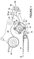
- Figures 1 and 2 depict a material reduction apparatus in accordance with various embodiments of the present invention.
- the material reduction apparatus comprises a conveyor 14 for moving material to be reduced 12a toward a rotor 16 including radial projections 18 (sometimes referred to in the art as hammers).
- a compression roller 20 includes ribs 22 mounted on a pivotal arm 24. Compression roller 20 may be configured such that compression roller 20 is urged generally downward toward conveyor 14 and/or rotor 16. Compression roller 20 working in conjunction with conveyor 14 may urge material 12a downward and inward in the direction of arrow 34 toward rotor 16.
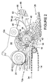
- material 12a may be forced against rotor 16 and/or projections 18 and is carried upwardly by projections 18 into engagement with an anvil 36 of a bypass arm 90. Material 12a that is too large to fit between the spacing provided between projections 18 and anvil 36 may be broken into smaller pieces upon impacting anvil 36.
- Bypass arm 90 may further include a screen 38 following anvil 36 in around rotor 16.
- following screen 38 may be one or more other screen sections 40, 42.
- Material 12a may be reduced by the apparatus into smaller pieces, which may then be urged by projections 18 against screens 38, 40, 42 and in some cases reduced further.
- Reduced material 12b may then pass through one or more of screens 38, 40, 42.
- reduced material 12b may be deposited onto a conveyor for conveying away from the apparatus. Material 12a not passing through one or more of screens 38, 40, 42 may be moved around rotor 16 via projections 18 one or more additional cycles for further reduction and/or screening.
- Material to be reduced 12a may include one or more reduction-resistant objects 12c as illustrated in Figures 2 and 3 .
- Such reduction-resistant objects 12c may impact anvil 36, and the force of the impact, either alone or in combination with the added force of projections 18 due to the rotation of rotor 16, may result in pivoting of bypass arm 90 from a closed or operational position to a non-closed or open position for allowing reduction-resistant objects 12c to bypass the apparatus.
- bypass arm 90 may open a varying amount depending on a number of factors including, but not limited to, reduction-resistant material size, opening force caused by reduction-resistant objects 12c, and/or the resistance force applied by bypass arm 90. Allowing reduction-resistant material 12c to bypass the machine may avoid jamming of the rotor and/or damage to one or more components of the apparatus. Costly downtime, repairs, and/or replacement may thus be avoided or minimized.
- the material reducing apparatus may include a bypass arm 90 configured to pivot between a closed position and a non-closed position (illustrated in FIG. 3 ) to allow reduction-resistant objects 12c of material 12a to bypass the apparatus.
- a non-closed position may be any one or more positions of bypass arm 90 once bypass arm 90 has begun to pivot including, for example, fully open or any position between fully open and fully closed.
- Such pivoting of bypass arm 90 may be controlled, at least in part, by a bypass control member configured to move in relation to bypass arm 90 in order to allow bypass arm 90 to move between closed and non-closed positions.
- the bypass control member may be a lever 92, which may be configured to pivot about pivot point 93 between a first position when bypass arm 90 is in a closed position and a second position when bypass arm 90 is in the non-closed position.
- bypass control lever 92 may include a first interface feature 94 engaging an interface surface 91 of bypass arm 90 and a second interface feature 95 coupled to a resistance element 96.
- First interface feature 94 may be disposed on a first end of bypass control lever 92, with first interface feature 94 being configured to engage interface surface 91 of bypass arm 90 to allow bypass arm 90 to pivot between the closed position and the non-closed position.
- first interface feature 94 may rest at a home position of surface 91. In such a position, the first interface feature 94 may apply a predetermined force to bypass arm 90 in order to hold bypass arm 90 in the closed position until a force exceeding the predetermined force is provided by an impact of reduction-resistant objects 12c. When the predetermined force is overcome by the force caused by the reduction-resistant material, the interface feature and/or the interface surface will move relative to each other so as to allow bypass arm 90 to pivot to a non-closed position.
- first interface feature 94 may be configured to rotate such that it can rotatably or rollably engage surface 91 of bypass arm 90, while bypass arm 90 pivots between closed and non-closed positions.
- first interface feature 94 may comprise a roller or other rolling structure.
- first interface feature 94 depicts first interface feature 94 as having a generally circular shape, other configurations are possible within the scope of the present disclosure.
- first interface feature 94 may have an elliptical or other suitable shape. In other embodiments, however, first interface feature 94 may instead be configured to slidably engage surface 91, with first interface feature 94 and/or surface 91 of bypass arm 90 being formed of a suitable material and/or geometry that allows first interface feature 94 to slide relative to surface 91 of bypass arm 90.
- first interface feature 94 and/or surface 91 may be formed from and/or coated with a low- or no-friction material.
- Surface 91 of bypass arm 90 may take any one or more configurations.
- surface 91 may be integral to bypass arm 90 or may be formed by affixing a separate element to bypass arm 90.
- surface 91 may be a plate or plate-like structure affixed to bypass arm 90.
- Surface 91, whether integral or separately affixed, may be a generally smooth surface or may include one or more notches, detents or other interrupting features disposed thereon and/or therein. Such interrupting features may be configured to engage first interface feature 94 to inhibit, at least temporarily, movement of bypass arm 90 relative to first interface feature 94.
- a notch or detent may be configured to engage first interface feature 94 to inhibit movement of bypass arm 90 until a reduction-resistant object 12c is encountered (e.g., similar to the angularly offset home position illustrated and discussed above).
- interruption features may provide somewhat stepped but increased resistance to continued opening movement of bypass arm 90 as first interface feature 94 engages one or more of the detents until the reduction-resistant object 12c has passed.
- surface 91 may be generally smooth with first interface feature 94 resting on a top edge of surface 91 (i.e., the home position) until reduction-resistant material 12c is encountered.
- surface 91 may be geometrically configured with a contour adapted to provide a predetermined range and/or variation of resistance forces for resisting pivoting of bypass arm 90 from a closed position to a non-closed position. Such a configuration may also urge bypass arm 90 from the non-closed position towards the closed position.
- Contour as used herein may include a generally regularly curved surface (whether convex or concave), a generally irregularly curved surface, a generally flat surface, and/or a combination thereof, depending on the particular application.
- the contour of surface 91 may be configured to provide a generally flat first or home position engagable by the first interface feature 94 and adapted to provide a predetermined force for holding bypass arm 90 in a closed position.
- the resistance forces applied to bypass arm 90 may increase until the force generated by the reduction-resistant object 12c exceeds the predetermined force generated by first interface feature 94 engaging the home position, at which time bypass arm 90 will move to the non-closed position (e.g., first interface feature 94 moves from the home position).
- the contour of surface 91 may be configured to provide relatively low resistance such that the reduction-resistant object 12c is more readily bypassed.
- surface 91 may be configured such that as bypass arm 90 pivots to non-closed positions higher resistance forces may be generated to urge bypass arm 90 back to the closed position; such varying resistance may be caused by the geometry of the interface surface 91.
- resistance element 96 coupled to a second interface feature of the bypass control member may be configured to resist pivoting of bypass control lever 92 as desired.
- resistance element 96 may be configured to provide a predetermined range and/or variation of resistance forces for resisting pivoting of bypass control lever 92, and thus pivoting of bypass arm 90.
- Resistance element 96 may comprise any one or more of various forms and materials and still be suitable for the purpose.
- resistance element 96 may comprise one or more airbags or airbag-like structures, one or more biasing elements (e.g., elastomeric structures, springs, etc.), or some combination thereof.
- one or more of the airbags may be formed from any material suitable for the purpose including, for example, a polymer or a fabric, or some other material suitable for holding air or some other gas while still providing a desired level of elasticity.
- the airbags may be stacked or may be distributed horizontally within the same plane, or some combination of both configurations.
- resistance element 96 may comprise one or more biasing elements such as, for example, springs.
- the biasing element may be stacked or may be distributed horizontally within the same plane, or some combination of both configurations.
- resistance element 96 may be configured to provide a predetermined force for holding and/or facilitating holding of bypass arm 90 in a closed position until bypass arm 90 encounters a reduction-resistant object 12c at which point resistance forces may increase until the force generated by the reduction-resistant object 12c exceeds the predetermined force.
- resistance element 96 may be further configured to taper off the resistance or otherwise reduce to allow bypass arm 90 to pivot to a non-closed position.
- resistance element 96 may be configured to provide relatively low resistance once the predetermined force is exceeded such that the reduction-resistant object 12c is more readily bypassed, and in these embodiments, resistance element 96 may be configured such that as bypass arm 90 pivots to non-closed positions higher resistance forces may be generated to urge bypass arm 90 back the closed position.
- bypass arm 90 may provide for controlling the range of resistance forces for resisting pivoting of bypass control lever 92, and thus bypass arm 90, either by including resistance element 95 or by including a contoured surface 91
- an increased range and/or variation of resistances may be possible by including both.
- the resistance forces possible by either resistance element 95 or contoured surface 91 alone may be limited due to either the mechanical limits of those elements and/or by the materials available for forming those elements. Combining both elements may advantageously allow for an increased resistance force.
- the variation of resistance forces may be more controllable or variable if both elements are combined.
- use of either resistance element 95 or by contouring surface 91 alone may be suitable for the material reducing needs for the particular application.
- the contour of the interface surface may be any one of a number of geometries aside from the illustrated increasing radius of curvature curved surface, including being generally flat.
- the home position may be angularly offset from the curved portion of the interface surface (as illustrated), or, for example, it may be of a different geometry, indented, protruded, or otherwise distinguished from the remainder of the interface surface and adapted to help provide an initial resistance force to hold the bypass arm in the closed position.
Landscapes
- Engineering & Computer Science (AREA)
- Food Science & Technology (AREA)
- Crushing And Grinding (AREA)
- Crushing And Pulverization Processes (AREA)
- Invalid Beds And Related Equipment (AREA)
- Pivots And Pivotal Connections (AREA)
- Press Drives And Press Lines (AREA)
- Apparatus For Radiation Diagnosis (AREA)
Description
- Embodiments of the present invention relate to machines and apparatuses for reducing material, e.g., for reducing material resulting from structural demolition to enable a more convenient transportation and disposal of such material.
- Material reducing machines have long been used for reducing material from larger-sized components to smaller-sized components. Such reduction may be desirable for any one or more reasons including, for example, transportability, re-usability, and/or degradability.
- In general, these machines operate by conveying un-reduced material toward a rotor having projections thereon, which may direct the material up and over the rotor into an overlying fixed anvil or anvil bar located in close proximity to the projections thereby breaking the material into smaller-sized components.
- Known material-reducing machines may not be suitable or desirable for all types of materials, particularly if there is a possibility that reduction-resistant object may be encountered. For example,
U.S. Patent No. 5,213,273 issued to Linnerz ("Linnerz") discloses a material-reducing machine including an open hydraulic system that includes a hydraulic cylinder, a pressure relief valve, and an open receiving tank as the structure to provide for what it calls "resilient deflection" of its outlet wall. Linnerz, however, fails to include a biasing arrangement for urging or causing the outlet wall to move back to its operating position, such that the outlet wall remains deflected away, requiring operator intervention to close the outlet wall. - Some material-reducing machines are configured with a shear pin that breaks when a reduction-resistant object is encountered, resulting in the bypass wall pivoting open. As a result, the processing operation must be shut down and the shear pin must be replaced.
- In still other cases, even more undesirable problems could result from a material-reducing machine encountering reduction-resistant material including, for example, damage to the machine, potentially leading to costly repairs or replacement thereof.
-
US 2005/0205702 discloses a material reduction apparatus for reducing materials having an admixture that resists reduction. The mechanism incorporated into the apparatus to provide a bypass of such admixture while avoiding shut down interruption of the materials reduction operation. - This apparatus comprises a relief mechanism including a pivotally mounted anvil, which is arranged to pivotally open when a substantial reduction or a resistant component is encountered and close back to the latched position once the component passes through the bypass as thus provided.
- The present invention provides a materials reduction apparatus according to claim 1.
- Embodiments of the present invention will be readily understood by the following detailed description in conjunction with the accompanying drawings. To facilitate this description, like reference numerals designate like structural elements. Embodiments of the invention are illustrated by way of example and not by way of limitation in the figures of the accompanying drawings.
-
Figure 1 is a schematic illustration of an exemplary material reduction apparatus, in accordance with various embodiments of the present invention. -
Figure 2 is a schematic illustration of the material reduction apparatus ofFigure 1 in use, in accordance with various embodiments of the present invention. -
Figure 3 is another schematic illustration of the material reduction apparatus ofFigure 1 in use, in accordance with various embodiments of the present invention. -
Figure 4 is another schematic illustration of the material reduction apparatus ofFigure 1 in use, in accordance with various embodiments of the present invention. - In the following detailed description, reference is made to the accompanying drawings which form a part hereof wherein like numerals designate like parts throughout, and in which is shown by way of illustration embodiments in which the invention may be practiced. It is to be understood that other embodiments may be utilized and structural or logical changes may be made without departing from the scope of the present invention. Therefore, the following detailed description is not to be taken in a limiting sense, and the scope of embodiments in accordance with the present invention is defined by the appended claims.
-
Figures 1 and2 depict a material reduction apparatus in accordance with various embodiments of the present invention. For the illustrated embodiment, the material reduction apparatus comprises aconveyor 14 for moving material to be reduced 12a toward arotor 16 including radial projections 18 (sometimes referred to in the art as hammers). Acompression roller 20 includesribs 22 mounted on apivotal arm 24.Compression roller 20 may be configured such thatcompression roller 20 is urged generally downward towardconveyor 14 and/orrotor 16.Compression roller 20 working in conjunction withconveyor 14 may urgematerial 12a downward and inward in the direction ofarrow 34 towardrotor 16. - In operation and as illustrated in
Figure 2 ,material 12a may be forced againstrotor 16 and/orprojections 18 and is carried upwardly byprojections 18 into engagement with ananvil 36 of abypass arm 90.Material 12a that is too large to fit between the spacing provided betweenprojections 18 andanvil 36 may be broken into smaller pieces upon impactinganvil 36. -
Bypass arm 90 may further include ascreen 38 followinganvil 36 in aroundrotor 16. In various embodiments, followingscreen 38 may be one or moreother screen sections Material 12a may be reduced by the apparatus into smaller pieces, which may then be urged byprojections 18 againstscreens material 12b may then pass through one or more ofscreens material 12b may be deposited onto a conveyor for conveying away from the apparatus.Material 12a not passing through one or more ofscreens rotor 16 viaprojections 18 one or more additional cycles for further reduction and/or screening. - Material to be reduced 12a, however, may include one or more reduction-
resistant objects 12c as illustrated inFigures 2 and3 . Such reduction-resistant objects 12c may impactanvil 36, and the force of the impact, either alone or in combination with the added force ofprojections 18 due to the rotation ofrotor 16, may result in pivoting ofbypass arm 90 from a closed or operational position to a non-closed or open position for allowing reduction-resistant objects 12c to bypass the apparatus. In various embodiments,bypass arm 90 may open a varying amount depending on a number of factors including, but not limited to, reduction-resistant material size, opening force caused by reduction-resistant objects 12c, and/or the resistance force applied bybypass arm 90. Allowing reduction-resistant material 12c to bypass the machine may avoid jamming of the rotor and/or damage to one or more components of the apparatus. Costly downtime, repairs, and/or replacement may thus be avoided or minimized. - To allow bypass of reduction-
resistant objects 12c, the material reducing apparatus may include abypass arm 90 configured to pivot between a closed position and a non-closed position (illustrated inFIG. 3 ) to allow reduction-resistant objects 12c ofmaterial 12a to bypass the apparatus. A non-closed position may be any one or more positions ofbypass arm 90 oncebypass arm 90 has begun to pivot including, for example, fully open or any position between fully open and fully closed. Such pivoting ofbypass arm 90 may be controlled, at least in part, by a bypass control member configured to move in relation tobypass arm 90 in order to allowbypass arm 90 to move between closed and non-closed positions. - In the illustrated embodiment, the bypass control member may be a
lever 92, which may be configured to pivot aboutpivot point 93 between a first position whenbypass arm 90 is in a closed position and a second position whenbypass arm 90 is in the non-closed position. - As illustrated,
bypass control lever 92 may include afirst interface feature 94 engaging aninterface surface 91 ofbypass arm 90 and asecond interface feature 95 coupled to aresistance element 96.First interface feature 94 may be disposed on a first end ofbypass control lever 92, withfirst interface feature 94 being configured to engageinterface surface 91 ofbypass arm 90 to allowbypass arm 90 to pivot between the closed position and the non-closed position. - In various embodiments, while reducing normally-reducible material,
first interface feature 94 may rest at a home position ofsurface 91. In such a position, thefirst interface feature 94 may apply a predetermined force to bypassarm 90 in order to holdbypass arm 90 in the closed position until a force exceeding the predetermined force is provided by an impact of reduction-resistant objects 12c. When the predetermined force is overcome by the force caused by the reduction-resistant material, the interface feature and/or the interface surface will move relative to each other so as to allowbypass arm 90 to pivot to a non-closed position. - In various embodiments,
first interface feature 94 may be configured to rotate such that it can rotatably or rollably engagesurface 91 ofbypass arm 90, whilebypass arm 90 pivots between closed and non-closed positions. For example, in various embodiments,first interface feature 94 may comprise a roller or other rolling structure. Although the illustrated embodiments depict first interface feature 94 as having a generally circular shape, other configurations are possible within the scope of the present disclosure. - For example, in some embodiments,
first interface feature 94 may have an elliptical or other suitable shape. In other embodiments, however,first interface feature 94 may instead be configured to slidably engagesurface 91, withfirst interface feature 94 and/orsurface 91 ofbypass arm 90 being formed of a suitable material and/or geometry that allowsfirst interface feature 94 to slide relative tosurface 91 ofbypass arm 90. For example, in one embodiment, first interface feature 94 and/orsurface 91 may be formed from and/or coated with a low- or no-friction material. -
Surface 91 ofbypass arm 90 may take any one or more configurations. For example,surface 91 may be integral tobypass arm 90 or may be formed by affixing a separate element tobypass arm 90. In embodiments, for example,surface 91 may be a plate or plate-like structure affixed tobypass arm 90.Surface 91, whether integral or separately affixed, may be a generally smooth surface or may include one or more notches, detents or other interrupting features disposed thereon and/or therein. Such interrupting features may be configured to engagefirst interface feature 94 to inhibit, at least temporarily, movement ofbypass arm 90 relative tofirst interface feature 94. For example, in some embodiments, a notch or detent may be configured to engagefirst interface feature 94 to inhibit movement ofbypass arm 90 until a reduction-resistant object 12c is encountered (e.g., similar to the angularly offset home position illustrated and discussed above). - In still further embodiments, interruption features may provide somewhat stepped but increased resistance to continued opening movement of
bypass arm 90 asfirst interface feature 94 engages one or more of the detents until the reduction-resistant object 12c has passed. In other embodiments and as illustrated inFigures 1-4 , however, surface 91 may be generally smooth withfirst interface feature 94 resting on a top edge of surface 91 (i.e., the home position) until reduction-resistant material 12c is encountered. - In various embodiments,
surface 91 may be geometrically configured with a contour adapted to provide a predetermined range and/or variation of resistance forces for resisting pivoting ofbypass arm 90 from a closed position to a non-closed position. Such a configuration may also urgebypass arm 90 from the non-closed position towards the closed position. "Contour" as used herein may include a generally regularly curved surface (whether convex or concave), a generally irregularly curved surface, a generally flat surface, and/or a combination thereof, depending on the particular application. - For example, the contour of
surface 91 may be configured to provide a generally flat first or home position engagable by thefirst interface feature 94 and adapted to provide a predetermined force for holdingbypass arm 90 in a closed position. When a reduction-resistant object 12c is encountered, the resistance forces applied to bypassarm 90 may increase until the force generated by the reduction-resistant object 12c exceeds the predetermined force generated byfirst interface feature 94 engaging the home position, at whichtime bypass arm 90 will move to the non-closed position (e.g.,first interface feature 94 moves from the home position). In various embodiments, the contour ofsurface 91 may be configured to provide relatively low resistance such that the reduction-resistant object 12c is more readily bypassed. In various embodiments,surface 91 may be configured such that asbypass arm 90 pivots to non-closed positions higher resistance forces may be generated to urgebypass arm 90 back to the closed position; such varying resistance may be caused by the geometry of theinterface surface 91. - In addition to or instead of contouring of
surface 91 for providing a varying range of resistance forces,resistance element 96 coupled to a second interface feature of the bypass control member (as illustrated, lever 92) may be configured to resist pivoting ofbypass control lever 92 as desired. For example,resistance element 96 may be configured to provide a predetermined range and/or variation of resistance forces for resisting pivoting ofbypass control lever 92, and thus pivoting ofbypass arm 90. -
Resistance element 96 may comprise any one or more of various forms and materials and still be suitable for the purpose. For example, for various embodiments,resistance element 96 may comprise one or more airbags or airbag-like structures, one or more biasing elements (e.g., elastomeric structures, springs, etc.), or some combination thereof. In embodiments whereinresistance element 96 comprises an airbag(s), one or more of the airbags may be formed from any material suitable for the purpose including, for example, a polymer or a fabric, or some other material suitable for holding air or some other gas while still providing a desired level of elasticity. For embodiments whereinresistance element 96 comprises multiple airbags, the airbags may be stacked or may be distributed horizontally within the same plane, or some combination of both configurations. - In some embodiments,
resistance element 96 may comprise one or more biasing elements such as, for example, springs. For embodiments whereinresistance element 96 comprises multiple biasing elements, the biasing element may be stacked or may be distributed horizontally within the same plane, or some combination of both configurations. - In various embodiments, and similarly to various embodiments of
surface 91 described above,resistance element 96 may be configured to provide a predetermined force for holding and/or facilitating holding ofbypass arm 90 in a closed position untilbypass arm 90 encounters a reduction-resistant object 12c at which point resistance forces may increase until the force generated by the reduction-resistant object 12c exceeds the predetermined force. To allow the reduction-resistant object 12c to be bypassed from the apparatus,resistance element 96 may be further configured to taper off the resistance or otherwise reduce to allowbypass arm 90 to pivot to a non-closed position. In other embodiments, however,resistance element 96 may be configured to provide relatively low resistance once the predetermined force is exceeded such that the reduction-resistant object 12c is more readily bypassed, and in these embodiments,resistance element 96 may be configured such that asbypass arm 90 pivots to non-closed positions higher resistance forces may be generated to urgebypass arm 90 back the closed position. - Although various embodiments may provide for controlling the range of resistance forces for resisting pivoting of
bypass control lever 92, and thus bypassarm 90, either by includingresistance element 95 or by including a contouredsurface 91, an increased range and/or variation of resistances may be possible by including both. For example, the resistance forces possible by eitherresistance element 95 or contouredsurface 91 alone may be limited due to either the mechanical limits of those elements and/or by the materials available for forming those elements. Combining both elements may advantageously allow for an increased resistance force. Similarly, the variation of resistance forces may be more controllable or variable if both elements are combined. In some embodiments, however, use of eitherresistance element 95 or by contouringsurface 91 alone may be suitable for the material reducing needs for the particular application. - Although certain embodiments have been illustrated and described herein for purposes of description of the preferred embodiment, it will be appreciated by those of ordinary skill in the art that a wide variety of alternate and/or equivalent embodiments or implementations calculated to achieve the same purposes may be substituted for the embodiments shown and described without departing from the scope of the present invention. The contour of the interface surface may be any one of a number of geometries aside from the illustrated increasing radius of curvature curved surface, including being generally flat. The home position may be angularly offset from the curved portion of the interface surface (as illustrated), or, for example, it may be of a different geometry, indented, protruded, or otherwise distinguished from the remainder of the interface surface and adapted to help provide an initial resistance force to hold the bypass arm in the closed position. Those with skill in the art will readily appreciate that embodiments in accordance with the present invention may be implemented in a very wide variety of ways. This application is intended to cover any adaptations or variations of the embodiments discussed herein. Therefore, it is manifestly intended that embodiments in accordance with the present invention be limited only by the claims.
Claims (15)
- A materials reduction apparatus comprising:a bypass arm (90) configured to pivot between a closed position and a non-closed position to allow a reduction-resistant object of a material to bypass the apparatus; anda bypass control lever (92) configured to move between a first position when the bypass arm (90) is in a closed position and a second position when the bypass arm is in the non-closed position, the lever (92) including a rolling structure (94) configured to engage an interface surface (91) of the bypass arm (90).
- The apparatus of claim 1, wherein the interface surface has a first portion and a second portion angularly disposed from the first portion, and wherein the second portion is generally curved.
- The apparatus of claim 2, wherein the interface surface (91) of the bypass arm (90) is convexly curved relative to the rolling structure (94) of the control lever (92).
- The apparatus of claim 3, wherein the convexly curved surface of the bypass arm (90) provides a range of resistance forces for resisting pivoting of the bypass arm (90).
- The apparatus of claim 2, wherein the second portion has a non-constant radius of curvature.
- The apparatus of claim 1, wherein the interface surface (91) of the bypass arm (90) is generally flat.
- The apparatus of claim 1, wherein the surface (91) of the bypass arm (90) includes at least one notch or detent for engaging the rolling structure (94) of the control lever (92) to inhibit, at least temporarily, movement of the bypass arm (90) relative to the first end of the bypass control lever (92).
- The apparatus of claim 7, wherein the rolling structure (94) of the bypass control lever (92) engages the notch or detent to inhibit movement of the bypass arm (90) until the reduction-resistant object is encountered.
- The apparatus of claim 1, wherein the rolling structure (94) of the control member (92) comprises a roller that rotatably engages the interface surface (91) of the bypass arm (90).
- The apparatus of claim 1, wherein the control lever (92) coupled to the resistance element (96) are configured to resist movement of the bypass control lever (92) from the first position and the second position.
- The apparatus of claim 10, wherein the resistance element (96) urges the bypass control lever (92) to return to the first position and thereby to urge the bypass arm (90) to pivot towards the closed position.
- The apparatus of claim 10, wherein the resistance element (96) is configured to provide a range of resistance forces for resisting movement of the bypass control lever (92).
- The apparatus of claim 10, wherein the resistance element (96) comprises at least a selected one or more of an airbag, a spring, and an elastomer.
- The apparatus of claim 1, wherein the bypass arm (90) is pivotally coupled to a shaft, and wherein the apparatus further comprises a shear pin coupled to the shaft and adapted to shear when the bypass arm (90) encounters the reduction-resistant object.
- The apparatus of claim 1, wherein the bypass arm (90) is pivotally coupled to a shaft, and wherein the apparatus further comprises a compression member coupled to the shaft to allow limited generally linear movement of the shaft.
Applications Claiming Priority (2)
| Application Number | Priority Date | Filing Date | Title |
|---|---|---|---|
| US11/740,531 US7832670B2 (en) | 2004-03-19 | 2007-04-26 | Material reducing apparatus |
| PCT/US2008/061646 WO2008134565A1 (en) | 2007-04-26 | 2008-04-25 | Material reducing apparatus |
Publications (3)
| Publication Number | Publication Date |
|---|---|
| EP2152420A1 EP2152420A1 (en) | 2010-02-17 |
| EP2152420A4 EP2152420A4 (en) | 2014-01-22 |
| EP2152420B1 true EP2152420B1 (en) | 2016-04-13 |
Family
ID=38603929
Family Applications (1)
| Application Number | Title | Priority Date | Filing Date |
|---|---|---|---|
| EP08746956.5A Active EP2152420B1 (en) | 2007-04-26 | 2008-04-25 | Material reducing apparatus |
Country Status (7)
| Country | Link |
|---|---|
| US (1) | US7832670B2 (en) |
| EP (1) | EP2152420B1 (en) |
| JP (1) | JP5356369B2 (en) |
| CN (1) | CN101668591B (en) |
| AU (1) | AU2008245605B2 (en) |
| CA (1) | CA2683420C (en) |
| WO (1) | WO2008134565A1 (en) |
Families Citing this family (27)
| Publication number | Priority date | Publication date | Assignee | Title |
|---|---|---|---|---|
| JP4809238B2 (en) * | 2004-10-21 | 2011-11-09 | 日立建機株式会社 | Wood crusher |
| US8191810B2 (en) * | 2008-05-08 | 2012-06-05 | Hitachi Construction Machinery Co., Ltd. | Crusher |
| US20100155513A1 (en) * | 2008-12-19 | 2010-06-24 | Rotochopper, Inc. | Bale breaker apparatus and method |
| US8152081B2 (en) * | 2009-08-12 | 2012-04-10 | Harris Waste Management Group, Inc. | Comminuting machine containment system |
| US8632024B2 (en) | 2010-01-25 | 2014-01-21 | Organic Energy Corporation | Systems and methods for processing mixed solid waste |
| US9713812B1 (en) | 2011-09-12 | 2017-07-25 | Organic Energy Corporation | Methods and systems for separating and recovering recyclables using a comminution device |
| US9700896B1 (en) | 2013-02-16 | 2017-07-11 | Organic Energy Corporation | Systems and methods for processing mixed solid waste |
| US8322639B2 (en) | 2010-11-24 | 2012-12-04 | Organic Energy Corporation | Mechanized separation of mixed solid waste and recovery of recyclable products |
| US8398006B2 (en) | 2010-11-24 | 2013-03-19 | Organic Energy Corporation | Mechanized separation of mixed solid waste and recovery of recyclable products |
| US20140175201A1 (en) * | 2012-12-21 | 2014-06-26 | Astec Industries, Inc. | Material Reducing Device |
| US10099224B2 (en) * | 2011-12-22 | 2018-10-16 | Astec Industries, Inc. | Material reducing device |
| US9186684B2 (en) | 2012-04-16 | 2015-11-17 | Harris Waste Management Group, Inc. | Comminuting machine drive system |
| JP5731442B2 (en) * | 2012-05-31 | 2015-06-10 | 日立建機株式会社 | Crushing machine |
| EP2877285B1 (en) * | 2012-06-28 | 2020-10-07 | Cellulose Insulation Production Scandinavia CPS AB | Device for dissolving compressed blocks of insulation, a loose fill insulation apparatus and a method for dissolving compressed blocks of insulation |
| DK2976157T3 (en) * | 2013-03-18 | 2019-01-07 | Astec Ind | Material reducing machine |
| DK178385B1 (en) * | 2014-10-03 | 2016-01-25 | Maskinfabrikken Cormall As | Straw riser for tearing up and partially breaking down biomass material |
| CN104890078B (en) * | 2015-06-26 | 2017-08-04 | 上海明励机械有限公司 | Branch crushing machine |
| DE102017006098B3 (en) * | 2017-06-28 | 2018-12-27 | Doppstadt Familienholding Gmbh | comminution device |
| US10807098B1 (en) * | 2017-07-26 | 2020-10-20 | Pearson Incorporated | Systems and methods for step grinding |
| DE102019007192A1 (en) * | 2019-10-16 | 2021-04-22 | Siempelkamp Maschinen- Und Anlagenbau Gmbh | Device for comminuting bulk material and a method for opening such a device |
| US10757860B1 (en) | 2019-10-31 | 2020-09-01 | Hemp Processing Solutions, LLC | Stripper apparatus crop harvesting system |
| US10933424B1 (en) | 2019-12-11 | 2021-03-02 | Pearson Incorporated | Grinding roll improvements |
| CN111037795A (en) * | 2019-12-12 | 2020-04-21 | 邹子昊 | Elastic plastic processing reducing mechanism |
| US11712701B2 (en) | 2020-07-06 | 2023-08-01 | Alamo Group Inc. | Wood grinding machine with vibration detection system and related methods |
| US11980892B2 (en) | 2021-07-20 | 2024-05-14 | C. W. Mill Equipment Co., Inc. | Horizontal grinder with upward rotating mill and contamination bypass |
| CN115254307B (en) * | 2022-06-22 | 2023-07-07 | 常州市佳华机械科技有限公司 | Novel pulverizer system for starch production |
| US12521728B1 (en) | 2023-05-26 | 2026-01-13 | James R. Fincher Timber Co., Inc. | Conveyor drum chipper with screen |
Family Cites Families (27)
| Publication number | Priority date | Publication date | Assignee | Title |
|---|---|---|---|---|
| USRE17120E (en) | 1928-10-30 | Ensilage cutter | ||
| US953111A (en) | 1908-11-04 | 1910-03-29 | Williams Patent Crusher & Pulv | Cage for shredding-machines. |
| US1776593A (en) | 1928-09-04 | 1930-09-23 | I B Rowell Co | Combination feed cutter and hammer mill |
| US1816097A (en) | 1930-01-27 | 1931-07-28 | Thomas B Sumner | Sawmill hog |
| US2305159A (en) * | 1941-08-04 | 1942-12-15 | Heckman Frank | Attachment for threshing machines |
| US3868062A (en) | 1974-03-25 | 1975-02-25 | Coats Company Inc | Tire shredding machine |
| US4318512A (en) | 1978-10-26 | 1982-03-09 | Jacobson Machine Works, Inc. | Quick action screen latching apparatus for hammermill |
| US4385732A (en) | 1980-08-29 | 1983-05-31 | Williams Robert M | Waste material breaking and shredding apparatus |
| DE3624826A1 (en) | 1986-07-23 | 1988-02-04 | Lindemann Maschfab Gmbh | RUST FOR CRUSHING MACHINES |
| US4773601A (en) | 1986-09-29 | 1988-09-27 | S.B.O., Inc. | Combination small-scale tub grinder and wood chipper |
| DE3643529C1 (en) | 1986-12-19 | 1988-03-17 | Thyssen Industrie | Sorting device in the good outlet of a shredding machine for scrap |
| US5213273A (en) | 1990-05-21 | 1993-05-25 | Lindemann Maschinenfabrik Gmbh | Hammer mill |
| US5273218A (en) | 1990-08-20 | 1993-12-28 | Burns Leslie L | Falcon hog |
| ATE112445T1 (en) | 1991-03-25 | 1994-10-15 | Willibald Gmbh Maschinenfabrik | MOBILE SHREDDING DEVICE FOR ORGANIC WASTE MATERIALS. |
| FR2703928B1 (en) | 1993-04-16 | 1995-06-23 | Caruelle | APPARATUS FOR FRAGMING SOLID OBJECTS. |
| DE9305854U1 (en) | 1993-04-20 | 1993-06-17 | Doppstadt, Werner, 5620 Velbert | Shredding plant with pre-shredding |
| US5358189A (en) | 1993-09-29 | 1994-10-25 | Aldo Vandermolen | Processor for chipping and shredding vegetation |
| US5417375A (en) | 1994-02-22 | 1995-05-23 | Peterson Pacific Corporation | Material reducing machine |
| US5695134A (en) | 1996-04-10 | 1997-12-09 | Williams; Robert M. | Material reducing hammer mill with internal air circulating fan |
| US5743472A (en) * | 1997-01-28 | 1998-04-28 | Williams Patent Crusher & Pulverizer Company | Material reduction apparatus |
| US5947395A (en) | 1997-09-22 | 1999-09-07 | Peterson Pacific Corp. | Materials reducing machine |
| CA2456442C (en) | 2001-08-21 | 2010-08-03 | Peterson Pacific Corporation | Side removal screen system for materials reducing machines |
| US7090157B2 (en) | 2004-03-19 | 2006-08-15 | Peterson Pacific Corp. | Material reducing apparatus |
| JP4681888B2 (en) * | 2005-01-14 | 2011-05-11 | 日立建機株式会社 | Wood crusher |
| JP2007245070A (en) * | 2006-03-17 | 2007-09-27 | Hitachi Constr Mach Co Ltd | Wood crusher |
| US8191810B2 (en) * | 2008-05-08 | 2012-06-05 | Hitachi Construction Machinery Co., Ltd. | Crusher |
| JP5080350B2 (en) * | 2008-05-08 | 2012-11-21 | 日立建機株式会社 | Crushing machine |
-
2007
- 2007-04-26 US US11/740,531 patent/US7832670B2/en not_active Expired - Lifetime
-
2008
- 2008-04-25 AU AU2008245605A patent/AU2008245605B2/en active Active
- 2008-04-25 JP JP2010506538A patent/JP5356369B2/en active Active
- 2008-04-25 WO PCT/US2008/061646 patent/WO2008134565A1/en not_active Ceased
- 2008-04-25 EP EP08746956.5A patent/EP2152420B1/en active Active
- 2008-04-25 CA CA2683420A patent/CA2683420C/en active Active
- 2008-04-25 CN CN2008800135567A patent/CN101668591B/en not_active Expired - Fee Related
Also Published As
| Publication number | Publication date |
|---|---|
| WO2008134565A1 (en) | 2008-11-06 |
| CN101668591A (en) | 2010-03-10 |
| US7832670B2 (en) | 2010-11-16 |
| US20070241218A1 (en) | 2007-10-18 |
| JP2010524686A (en) | 2010-07-22 |
| CA2683420A1 (en) | 2008-11-06 |
| EP2152420A4 (en) | 2014-01-22 |
| AU2008245605B2 (en) | 2012-01-19 |
| AU2008245605A1 (en) | 2008-11-06 |
| CA2683420C (en) | 2015-08-11 |
| CN101668591B (en) | 2012-01-11 |
| EP2152420A1 (en) | 2010-02-17 |
| JP5356369B2 (en) | 2013-12-04 |
Similar Documents
| Publication | Publication Date | Title |
|---|---|---|
| CA2683420C (en) | Material reducing apparatus | |
| US8191810B2 (en) | Crusher | |
| JP7438411B2 (en) | Safety brakes for circular saw blades, circular saws including safety brakes, and how to operate circular saws | |
| WO2010071550A2 (en) | Horizontal shaft impact crusher | |
| SE1050377A1 (en) | Impact crusher with horizontal axis | |
| EP2229613A1 (en) | Pedal arrangement with a standing pedal pivoting about a horizontal axis | |
| JP5657454B2 (en) | silo | |
| US7232084B2 (en) | Material reducing apparatus | |
| US20050150343A1 (en) | Device located on scrap shears or similar for reducing the frictional forces that occur as a result of the action of the material to be crushed on the closing motion | |
| EP1637700B1 (en) | Variable bladed nozzle of a turbomachine and turbomachine | |
| EP0431473B1 (en) | Paper guide device | |
| EP1771609B1 (en) | Rotor brake for a spinning rotor | |
| US7699301B2 (en) | Printed product processing device with cam lever inhibit mechanism and cam inhibit method | |
| JP2023120819A (en) | Rotating mechanism and boarding/exiting device equipped with the same | |
| EP4450404A1 (en) | Vertical packaging machine | |
| WO2007102789A1 (en) | Perforator | |
| CN101473395A (en) | Manipulator for operating safety switch | |
| CN113365807A (en) | Lifting device for working table of lithographic plate laminating machine | |
| JP2019084597A (en) | Ring installation device |
Legal Events
| Date | Code | Title | Description |
|---|---|---|---|
| PUAI | Public reference made under article 153(3) epc to a published international application that has entered the european phase |
Free format text: ORIGINAL CODE: 0009012 |
|
| 17P | Request for examination filed |
Effective date: 20091123 |
|
| AK | Designated contracting states |
Kind code of ref document: A1 Designated state(s): AT BE BG CH CY CZ DE DK EE ES FI FR GB GR HR HU IE IS IT LI LT LU LV MC MT NL NO PL PT RO SE SI SK TR |
|
| AX | Request for extension of the european patent |
Extension state: AL BA MK RS |
|
| RIN1 | Information on inventor provided before grant (corrected) |
Inventor name: BITTROLF, GLENN, FORD Inventor name: PETERSON, ARNOLD, N. |
|
| DAX | Request for extension of the european patent (deleted) | ||
| A4 | Supplementary search report drawn up and despatched |
Effective date: 20131220 |
|
| RIC1 | Information provided on ipc code assigned before grant |
Ipc: B02C 13/09 20060101ALN20131216BHEP Ipc: B02C 13/00 20060101ALI20131216BHEP Ipc: B02C 13/31 20060101AFI20131216BHEP Ipc: B02C 13/286 20060101ALI20131216BHEP |
|
| 17Q | First examination report despatched |
Effective date: 20140911 |
|
| REG | Reference to a national code |
Ref country code: DE Ref legal event code: R079 Ref document number: 602008043517 Country of ref document: DE Free format text: PREVIOUS MAIN CLASS: B02C0013090000 Ipc: B02C0013310000 |
|
| GRAP | Despatch of communication of intention to grant a patent |
Free format text: ORIGINAL CODE: EPIDOSNIGR1 |
|
| RIC1 | Information provided on ipc code assigned before grant |
Ipc: B02C 13/31 20060101AFI20150930BHEP Ipc: B02C 13/09 20060101ALN20150930BHEP Ipc: B02C 13/286 20060101ALI20150930BHEP Ipc: B02C 13/00 20060101ALI20150930BHEP |
|
| INTG | Intention to grant announced |
Effective date: 20151030 |
|
| RIN1 | Information on inventor provided before grant (corrected) |
Inventor name: BITTROLF, GLENN FORD Inventor name: PETERSON, ARNOLD N. |
|
| GRAS | Grant fee paid |
Free format text: ORIGINAL CODE: EPIDOSNIGR3 |
|
| GRAA | (expected) grant |
Free format text: ORIGINAL CODE: 0009210 |
|
| AK | Designated contracting states |
Kind code of ref document: B1 Designated state(s): AT BE BG CH CY CZ DE DK EE ES FI FR GB GR HR HU IE IS IT LI LT LU LV MC MT NL NO PL PT RO SE SI SK TR |
|
| REG | Reference to a national code |
Ref country code: GB Ref legal event code: FG4D |
|
| REG | Reference to a national code |
Ref country code: AT Ref legal event code: REF Ref document number: 789536 Country of ref document: AT Kind code of ref document: T Effective date: 20160415 Ref country code: CH Ref legal event code: EP |
|
| REG | Reference to a national code |
Ref country code: IE Ref legal event code: FG4D |
|
| REG | Reference to a national code |
Ref country code: SE Ref legal event code: TRGR |
|
| REG | Reference to a national code |
Ref country code: DE Ref legal event code: R096 Ref document number: 602008043517 Country of ref document: DE |
|
| REG | Reference to a national code |
Ref country code: NL Ref legal event code: FP |
|
| REG | Reference to a national code |
Ref country code: FR Ref legal event code: PLFP Year of fee payment: 9 |
|
| REG | Reference to a national code |
Ref country code: LT Ref legal event code: MG4D |
|
| PG25 | Lapsed in a contracting state [announced via postgrant information from national office to epo] |
Ref country code: BE Free format text: LAPSE BECAUSE OF NON-PAYMENT OF DUE FEES Effective date: 20160430 |
|
| REG | Reference to a national code |
Ref country code: AT Ref legal event code: MK05 Ref document number: 789536 Country of ref document: AT Kind code of ref document: T Effective date: 20160413 |
|
| PG25 | Lapsed in a contracting state [announced via postgrant information from national office to epo] |
Ref country code: NO Free format text: LAPSE BECAUSE OF FAILURE TO SUBMIT A TRANSLATION OF THE DESCRIPTION OR TO PAY THE FEE WITHIN THE PRESCRIBED TIME-LIMIT Effective date: 20160713 Ref country code: LT Free format text: LAPSE BECAUSE OF FAILURE TO SUBMIT A TRANSLATION OF THE DESCRIPTION OR TO PAY THE FEE WITHIN THE PRESCRIBED TIME-LIMIT Effective date: 20160413 Ref country code: PL Free format text: LAPSE BECAUSE OF FAILURE TO SUBMIT A TRANSLATION OF THE DESCRIPTION OR TO PAY THE FEE WITHIN THE PRESCRIBED TIME-LIMIT Effective date: 20160413 |
|
| PG25 | Lapsed in a contracting state [announced via postgrant information from national office to epo] |
Ref country code: ES Free format text: LAPSE BECAUSE OF FAILURE TO SUBMIT A TRANSLATION OF THE DESCRIPTION OR TO PAY THE FEE WITHIN THE PRESCRIBED TIME-LIMIT Effective date: 20160413 Ref country code: PT Free format text: LAPSE BECAUSE OF FAILURE TO SUBMIT A TRANSLATION OF THE DESCRIPTION OR TO PAY THE FEE WITHIN THE PRESCRIBED TIME-LIMIT Effective date: 20160816 Ref country code: HR Free format text: LAPSE BECAUSE OF FAILURE TO SUBMIT A TRANSLATION OF THE DESCRIPTION OR TO PAY THE FEE WITHIN THE PRESCRIBED TIME-LIMIT Effective date: 20160413 Ref country code: GR Free format text: LAPSE BECAUSE OF FAILURE TO SUBMIT A TRANSLATION OF THE DESCRIPTION OR TO PAY THE FEE WITHIN THE PRESCRIBED TIME-LIMIT Effective date: 20160714 Ref country code: AT Free format text: LAPSE BECAUSE OF FAILURE TO SUBMIT A TRANSLATION OF THE DESCRIPTION OR TO PAY THE FEE WITHIN THE PRESCRIBED TIME-LIMIT Effective date: 20160413 Ref country code: LV Free format text: LAPSE BECAUSE OF FAILURE TO SUBMIT A TRANSLATION OF THE DESCRIPTION OR TO PAY THE FEE WITHIN THE PRESCRIBED TIME-LIMIT Effective date: 20160413 |
|
| REG | Reference to a national code |
Ref country code: CH Ref legal event code: PL |
|
| PG25 | Lapsed in a contracting state [announced via postgrant information from national office to epo] |
Ref country code: IT Free format text: LAPSE BECAUSE OF FAILURE TO SUBMIT A TRANSLATION OF THE DESCRIPTION OR TO PAY THE FEE WITHIN THE PRESCRIBED TIME-LIMIT Effective date: 20160413 Ref country code: BE Free format text: LAPSE BECAUSE OF FAILURE TO SUBMIT A TRANSLATION OF THE DESCRIPTION OR TO PAY THE FEE WITHIN THE PRESCRIBED TIME-LIMIT Effective date: 20160413 |
|
| REG | Reference to a national code |
Ref country code: DE Ref legal event code: R097 Ref document number: 602008043517 Country of ref document: DE |
|
| REG | Reference to a national code |
Ref country code: IE Ref legal event code: MM4A |
|
| PG25 | Lapsed in a contracting state [announced via postgrant information from national office to epo] |
Ref country code: CH Free format text: LAPSE BECAUSE OF NON-PAYMENT OF DUE FEES Effective date: 20160430 Ref country code: RO Free format text: LAPSE BECAUSE OF FAILURE TO SUBMIT A TRANSLATION OF THE DESCRIPTION OR TO PAY THE FEE WITHIN THE PRESCRIBED TIME-LIMIT Effective date: 20160413 Ref country code: MC Free format text: LAPSE BECAUSE OF FAILURE TO SUBMIT A TRANSLATION OF THE DESCRIPTION OR TO PAY THE FEE WITHIN THE PRESCRIBED TIME-LIMIT Effective date: 20160413 Ref country code: SK Free format text: LAPSE BECAUSE OF FAILURE TO SUBMIT A TRANSLATION OF THE DESCRIPTION OR TO PAY THE FEE WITHIN THE PRESCRIBED TIME-LIMIT Effective date: 20160413 Ref country code: LI Free format text: LAPSE BECAUSE OF NON-PAYMENT OF DUE FEES Effective date: 20160430 Ref country code: CZ Free format text: LAPSE BECAUSE OF FAILURE TO SUBMIT A TRANSLATION OF THE DESCRIPTION OR TO PAY THE FEE WITHIN THE PRESCRIBED TIME-LIMIT Effective date: 20160413 Ref country code: DK Free format text: LAPSE BECAUSE OF FAILURE TO SUBMIT A TRANSLATION OF THE DESCRIPTION OR TO PAY THE FEE WITHIN THE PRESCRIBED TIME-LIMIT Effective date: 20160413 Ref country code: EE Free format text: LAPSE BECAUSE OF FAILURE TO SUBMIT A TRANSLATION OF THE DESCRIPTION OR TO PAY THE FEE WITHIN THE PRESCRIBED TIME-LIMIT Effective date: 20160413 |
|
| PLBE | No opposition filed within time limit |
Free format text: ORIGINAL CODE: 0009261 |
|
| STAA | Information on the status of an ep patent application or granted ep patent |
Free format text: STATUS: NO OPPOSITION FILED WITHIN TIME LIMIT |
|
| 26N | No opposition filed |
Effective date: 20170116 |
|
| REG | Reference to a national code |
Ref country code: FR Ref legal event code: PLFP Year of fee payment: 10 |
|
| PG25 | Lapsed in a contracting state [announced via postgrant information from national office to epo] |
Ref country code: SI Free format text: LAPSE BECAUSE OF FAILURE TO SUBMIT A TRANSLATION OF THE DESCRIPTION OR TO PAY THE FEE WITHIN THE PRESCRIBED TIME-LIMIT Effective date: 20160413 Ref country code: IE Free format text: LAPSE BECAUSE OF NON-PAYMENT OF DUE FEES Effective date: 20160425 |
|
| REG | Reference to a national code |
Ref country code: FR Ref legal event code: PLFP Year of fee payment: 11 |
|
| PG25 | Lapsed in a contracting state [announced via postgrant information from national office to epo] |
Ref country code: HU Free format text: LAPSE BECAUSE OF FAILURE TO SUBMIT A TRANSLATION OF THE DESCRIPTION OR TO PAY THE FEE WITHIN THE PRESCRIBED TIME-LIMIT; INVALID AB INITIO Effective date: 20080425 Ref country code: CY Free format text: LAPSE BECAUSE OF FAILURE TO SUBMIT A TRANSLATION OF THE DESCRIPTION OR TO PAY THE FEE WITHIN THE PRESCRIBED TIME-LIMIT Effective date: 20160413 |
|
| PG25 | Lapsed in a contracting state [announced via postgrant information from national office to epo] |
Ref country code: MT Free format text: LAPSE BECAUSE OF NON-PAYMENT OF DUE FEES Effective date: 20160430 Ref country code: TR Free format text: LAPSE BECAUSE OF FAILURE TO SUBMIT A TRANSLATION OF THE DESCRIPTION OR TO PAY THE FEE WITHIN THE PRESCRIBED TIME-LIMIT Effective date: 20160413 Ref country code: LU Free format text: LAPSE BECAUSE OF NON-PAYMENT OF DUE FEES Effective date: 20160425 Ref country code: IS Free format text: LAPSE BECAUSE OF FAILURE TO SUBMIT A TRANSLATION OF THE DESCRIPTION OR TO PAY THE FEE WITHIN THE PRESCRIBED TIME-LIMIT Effective date: 20160413 |
|
| PG25 | Lapsed in a contracting state [announced via postgrant information from national office to epo] |
Ref country code: BG Free format text: LAPSE BECAUSE OF FAILURE TO SUBMIT A TRANSLATION OF THE DESCRIPTION OR TO PAY THE FEE WITHIN THE PRESCRIBED TIME-LIMIT Effective date: 20160413 |
|
| PGFP | Annual fee paid to national office [announced via postgrant information from national office to epo] |
Ref country code: FR Payment date: 20210421 Year of fee payment: 14 Ref country code: FI Payment date: 20210420 Year of fee payment: 14 |
|
| PGFP | Annual fee paid to national office [announced via postgrant information from national office to epo] |
Ref country code: SE Payment date: 20210420 Year of fee payment: 14 |
|
| PGFP | Annual fee paid to national office [announced via postgrant information from national office to epo] |
Ref country code: NL Payment date: 20210421 Year of fee payment: 14 |
|
| REG | Reference to a national code |
Ref country code: SE Ref legal event code: EUG |
|
| REG | Reference to a national code |
Ref country code: NL Ref legal event code: MM Effective date: 20220501 |
|
| PG25 | Lapsed in a contracting state [announced via postgrant information from national office to epo] |
Ref country code: SE Free format text: LAPSE BECAUSE OF NON-PAYMENT OF DUE FEES Effective date: 20220426 Ref country code: NL Free format text: LAPSE BECAUSE OF NON-PAYMENT OF DUE FEES Effective date: 20220501 Ref country code: FR Free format text: LAPSE BECAUSE OF NON-PAYMENT OF DUE FEES Effective date: 20220430 Ref country code: FI Free format text: LAPSE BECAUSE OF NON-PAYMENT OF DUE FEES Effective date: 20220425 |
|
| P01 | Opt-out of the competence of the unified patent court (upc) registered |
Effective date: 20230526 |
|
| PGFP | Annual fee paid to national office [announced via postgrant information from national office to epo] |
Ref country code: DE Payment date: 20250420 Year of fee payment: 18 |
|
| PGFP | Annual fee paid to national office [announced via postgrant information from national office to epo] |
Ref country code: GB Payment date: 20260330 Year of fee payment: 19 |