EP2152053B1 - Fixing heat dissipating unit and electronic device having fixing heat dissipating unit - Google Patents
Fixing heat dissipating unit and electronic device having fixing heat dissipating unit Download PDFInfo
- Publication number
- EP2152053B1 EP2152053B1 EP08171367.9A EP08171367A EP2152053B1 EP 2152053 B1 EP2152053 B1 EP 2152053B1 EP 08171367 A EP08171367 A EP 08171367A EP 2152053 B1 EP2152053 B1 EP 2152053B1
- Authority
- EP
- European Patent Office
- Prior art keywords
- substrate
- electronic device
- heat
- fixing
- heat dissipating
- Prior art date
- Legal status (The legal status is an assumption and is not a legal conclusion. Google has not performed a legal analysis and makes no representation as to the accuracy of the status listed.)
- Not-in-force
Links
Images


Classifications
-
- H—ELECTRICITY
- H05—ELECTRIC TECHNIQUES NOT OTHERWISE PROVIDED FOR
- H05K—PRINTED CIRCUITS; CASINGS OR CONSTRUCTIONAL DETAILS OF ELECTRIC APPARATUS; MANUFACTURE OF ASSEMBLAGES OF ELECTRICAL COMPONENTS
- H05K7/00—Constructional details common to different types of electric apparatus
- H05K7/20—Modifications to facilitate cooling, ventilating, or heating
- H05K7/2039—Modifications to facilitate cooling, ventilating, or heating characterised by the heat transfer by conduction from the heat generating element to a dissipating body
- H05K7/20436—Inner thermal coupling elements in heat dissipating housings, e.g. protrusions or depressions integrally formed in the housing
- H05K7/20445—Inner thermal coupling elements in heat dissipating housings, e.g. protrusions or depressions integrally formed in the housing the coupling element being an additional piece, e.g. thermal standoff
-
- H—ELECTRICITY
- H05—ELECTRIC TECHNIQUES NOT OTHERWISE PROVIDED FOR
- H05K—PRINTED CIRCUITS; CASINGS OR CONSTRUCTIONAL DETAILS OF ELECTRIC APPARATUS; MANUFACTURE OF ASSEMBLAGES OF ELECTRICAL COMPONENTS
- H05K7/00—Constructional details common to different types of electric apparatus
- H05K7/20—Modifications to facilitate cooling, ventilating, or heating
- H05K7/2039—Modifications to facilitate cooling, ventilating, or heating characterised by the heat transfer by conduction from the heat generating element to a dissipating body
- H05K7/20436—Inner thermal coupling elements in heat dissipating housings, e.g. protrusions or depressions integrally formed in the housing
- H05K7/2049—Pressing means used to urge contact, e.g. springs
-
- H—ELECTRICITY
- H05—ELECTRIC TECHNIQUES NOT OTHERWISE PROVIDED FOR
- H05K—PRINTED CIRCUITS; CASINGS OR CONSTRUCTIONAL DETAILS OF ELECTRIC APPARATUS; MANUFACTURE OF ASSEMBLAGES OF ELECTRICAL COMPONENTS
- H05K1/00—Printed circuits
- H05K1/02—Details
- H05K1/14—Structural association of two or more printed circuits
- H05K1/141—One or more single auxiliary printed circuits mounted on a main printed circuit, e.g. modules, adapters
-
- H—ELECTRICITY
- H05—ELECTRIC TECHNIQUES NOT OTHERWISE PROVIDED FOR
- H05K—PRINTED CIRCUITS; CASINGS OR CONSTRUCTIONAL DETAILS OF ELECTRIC APPARATUS; MANUFACTURE OF ASSEMBLAGES OF ELECTRICAL COMPONENTS
- H05K3/00—Apparatus or processes for manufacturing printed circuits
- H05K3/30—Assembling printed circuits with electric components, e.g. with resistors
- H05K3/301—Assembling printed circuits with electric components, e.g. with resistors by means of a mounting structure
-
- H—ELECTRICITY
- H05—ELECTRIC TECHNIQUES NOT OTHERWISE PROVIDED FOR
- H05K—PRINTED CIRCUITS; CASINGS OR CONSTRUCTIONAL DETAILS OF ELECTRIC APPARATUS; MANUFACTURE OF ASSEMBLAGES OF ELECTRICAL COMPONENTS
- H05K3/00—Apparatus or processes for manufacturing printed circuits
- H05K3/36—Assembling printed circuits with other printed circuits
- H05K3/366—Assembling printed circuits with other printed circuits substantially perpendicularly to each other
Definitions
- the present invention relates to a fixing heat dissipating unit with integrated functions of holding and heat dissipating, and an electronic device having the fixing heat dissipating unit.
- the elements inside such as the chips
- the elements inside usually generate heat energy.
- the accumulating heat energy may, however, easily overheat the electronic device and hence lead to the malfunction of the electronic device.
- the electronic device usually has a heat dissipating element, such as a fan, a metal heat dissipation sheet, a ceramic heat dissipation sheet, or a heat pipe, for heat dissipation.
- a heat dissipating element such as a fan, a metal heat dissipation sheet, a ceramic heat dissipation sheet, or a heat pipe, for heat dissipation.
- the fan or the heat pipe takes a lot of space in the electronic device; and as for the fan, the heat flow is also another factor to be considered while designing.
- the design cost will as well be increased.
- the fixing glue or a fixing element is normally used to hold or fix the elements for increasing the reliability of the electronic device.
- the metal fixing elements usually provide better steadiness for the elements.
- US 6,151,115 discloses an electronic device according to the preamble of claim 1. Two printed circuit boards (PCB) are held inside of the electronic device in parallel to each other by means of heat conducting plate, which is held in between the two PCBs and pressed against electronic components disposed on the PCBs.
- PCB printed circuit boards
- an electronic device including a fixing heat dissipating unit having integral design and an electronic device having this fixing heat dissipating unit, wherein the fixing heat dissipating unit is disposed in the electronic device.
- the fixing heat dissipating unit that is connected to a substrate and a heat source includes a fixing element and a heat conducting element.
- the fixing element is connected to the substrate to hold the substrate in the electronic device.
- the heat conducting element is connected to the heat source and the fixing element respectively.
- the heat source is a part of the electronic device, and the fixing element is integrated with the heat conducting element as a single component.
- the heat source is disposed on a surface of the first substrate, and the second substrate is disposed adjacent to the first substrate.
- the fixing heat dissipating unit is connected to the second substrate and the heat source respectively.
- the fixing heat dissipating unit includes a fixing element and a heat conducting element.
- the fixing element is connected to the second substrate to hold the second substrate in the electronic device, and the heat conducting element is connected to the heat source and the fixing element respectively.
- the fixing element is integrated with the heat conducting element as a single component.
- the fixing heat dissipating unit and the electronic device having the fixing heat dissipating unit according to the present invention transmit the heat energy generated by the heat source through the heat conducting element to the entire fixing heat dissipating unit so as to enhance the heat dissipating efficiency by increasing the heat dissipating area.
- the fixing heat dissipating unit and the electronic device of the present invention can match the positions of different substrates to provide the functions of heat dissipating and holding. Therefore, this can lower the design cost, reduce the testing time and effectively increase the reliability of the electronic product.
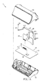
- FIG. 1A is an exploded view of an electronic device according to a preferred embodiment of the present invention.
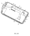
- FIG. 1B is an assembled view of a part of the electronic device in FIG. 1A ;
- FIG. 2 is a schematic view of another aspect of the fixing heat dissipating unit according to the preferred embodiment of the present invention.
- FIG. 3 is a schematic view of yet another aspect of a fixing heat dissipating unit.
- FIG. 1A is an exploded view of an electronic device according to a preferred embodiment of the present invention.
- FIG. 1B is an assembled view of a part of the electronic device in FIG. 1A .
- an electronic device 1 includes a first substrate 10, a heat source 20, a second substrate 30, and a fixing heat dissipating unit 40.
- the electronic device 1 may be a desktop, a laptop, an internet communication device, or a display device.
- the electronic device 1 is an internet communication device applied to, for example, ADSL or VDSL.
- the heat source 20 is disposed on a surface 11 of the first substrate 10.
- the heat source 20 is, for example, a chip or an active electronic element such as a transistor, which usually produces high temperature while operating.
- the first substrate 10 is a printed circuit board (PCB) or a glass circuit board (GCB) for example.
- a socket 12 is disposed on the surface 11 of the first substrate 10.
- the second substrate 30 is connected to the socket 12 and disposed adjacent to the first substrate 10.
- the first substrate 10 and the second substrate 30 are substantially perpendicular to each other.
- the second substrate 30 is electrically connected to the first substrate 10 through the socket 12 for signal transmission.
- the second substrate 30 may be a PCB or GCB for example.
- first substrate 10 and/or the second substrate 30 further includes one or more subsystems with an independent function
- first substrate 10 and/or the second substrate 30 is electrically connected to the electronic device 1 to become an integrated system with an integrated function.
- the independent function of the subsystem may be, for example, an operating function, signal receiving/transmitting function, or control function.
- the integrated system is, for example, a system having the integrated function of the above independent functions of the subsystems.
- the electronic device 1 may also include more substrates (not shown) in order to have various functions.
- the fixing heat dissipating unit 40 is disposed in the electronic device 1 and connects to the second substrate 30 and the heat source 20, respectively.
- the fixing heat dissipating unit 40 includes a fixing element 41 and a heat conducting element 42 that are connected to each other.
- the material of the fixing element 41 and the heat conducting element 42 may be a heat conducting material selected from at least one of a metal, an alloy, or a polymer material.
- the metal may be at least one of stannum (Sn), copper (Cu), aluminum (Al), or tin.
- the fixing element 41 at least includes a first opening 411 and a second opening 412, each of which is linked to at least one corner of the second substrate 30 to hold the second substrate 30 in the electronic device 1. That is, two corners of the second substrate 30 pass through the first opening 411 and the second opening 412 respectively.
- the heat conducting element 42 is connected to the heat source 20 and the fixing element 41 respectively.
- the heat source 20 is a part of the electronic device 1, and the fixing element 41 is integrated with the heat conducting element 42 as a single component.
- the heat conducting element 42 may contact the heat source 20 to conduct the heat energy generated by the heat source 20 to the fixing element 41, so as to dissipate the heat through the fixing heat dissipating unit 40.
- a heat dissipation sheet or a heat dissipation paste may be disposed between the heat conducting element 42 and the heat source 20 so as to enhance the heat conduction.
- the electronic device 1 further includes a housing having a lower housing 51 and an upper housing 52.
- the space formed by the housing is to contain the first substrate 10, the heat source 20, the second substrate 30, and the fixing heat dissipating unit 40.
- the positions and the dispositions of the first substrate 10, the second substrate 30, and the fixing heat dissipating unit 40 may be changed depending on the design of the lower housing 51 and the upper housing 52.
- two ends of the fixing unit 41 further have screw holes 413 and 414, respectively, for enhancing the structure of the electronic device 1.
- Screws 61 and 62 pass through the screw holes 413 and 414, respectively, and are screwed to the lower housing 51 so as to fix the fixing heat dissipating unit 40 to the lower housing 51.
- the fixing element 41 in the embodiment is fixed to the lower housing 51 by screwing, it can also be fixed to the lower housing 51 or the upper housing 52 by clipping or riveting according to the actual design needs.
- the fixing heat dissipating unit 40 may also, for example but not limited to, be screwed on the first substrate 10, for the prime concern is the structure stability.
- the assembled appearance of the lower housing 51 and the upper housing 52 in the embodiment is a triangle-like cylinder for example. It has a certain height so that after the electronic device 1 is connected to at least one peripheral expansion module or at least one connecting line (not shown), the structure of the electronic device 1 would still have a certain level of stability. If the fixing heat dissipating unit 40 is made of a metal or alloy, a weight allocating function may be provided after disposition so as to make the electronic device 1 more steady.
- a fixing element 41 a of a fixing heat dissipating unit 40a has only the first opening 411 for at least one corner of the second substrate 30 to pass through, hence to hold the second substrate 30 in the electronic device.
- One end of the fixing element 41 a also includes the screw hole.
- the fixing heat dissipating unit 40a and the lower housing 51 are locked by the screw 61, and the heat conducting element 42 is still integrated with the fixing element 41 as a single component.
- the heat conducting element 42 also contacts with the heat source 20 so as to conduct the heat energy generated by the heat source 20 to the fixing heat dissipating unit 40a for dissipating the heat.
- a heat dissipation sheet or a heat dissipation paste may be disposed between the heat conducting element 42 and the heat source 20 for enhancing the heat conduction.
- a second substrate 30a is disposed in parallel to a first substrate 10a, and two corners of the second substrate 30a pass through the first opening 411 and the second opening 412 of a fixing element 41b of a fixing heat dissipating unit 40b, respectively.
- the second substrate 30a is disposed substantially in parallel to the first substrate 10a, which further includes two supporting elements 13 and 14 for supporting the second substrate 30a.
- the second substrate 30a includes two openings 31 and 32, and two screws 63 and 64 pass through the openings 31 and 32, respectively, for connecting with the supporting elements 13 and 14. Therefore the second substrate 30a is held on the first substrate 10a by the fixing heat dissipating unit 40b and the supporting elements 13 and 14.
- the two ends of the fixing element 41b of the fixing heat dissipating unit 40b also have the screw holes respectively (not shown).
- the difference between this aspect and the above aspect is that the screws 61 and 62 pass through the two screw holes of the fixing element 41 b and then fix the fixing heat dissipating unit 40b on the first substrate 10a.
- the fixing heat dissipating unit 40b may also be fixed in the housing (not shown) according to the actual needs.
- a fixing heat dissipating unit and an electronic device having such according to the present invention integrate the fixing element and the heat dissipating element so that the heat energy generated by the heat source can be conducted to the entire fixing heat dissipating unit by contacting the heat conducting element, so as to enhance the heat dissipating efficiency by increasing the heat dissipating area.
- the present invention is able to lower the design cost and reduce the testing time of the fixing element and the heat dissipating element to control the production cost.
- the fixing heat dissipating unit and the electronic device of the present invention can provide the functions of heat dissipating, holding, and weight allocating, thereby effectively increasing the reliability of the electronic product.
Landscapes
- Physics & Mathematics (AREA)
- Thermal Sciences (AREA)
- Engineering & Computer Science (AREA)
- Microelectronics & Electronic Packaging (AREA)
- Cooling Or The Like Of Electrical Apparatus (AREA)
- Cooling Or The Like Of Semiconductors Or Solid State Devices (AREA)
Description
- The present invention relates to a fixing heat dissipating unit with integrated functions of holding and heat dissipating, and an electronic device having the fixing heat dissipating unit.
- As the electronic devices are operating, the elements inside, such as the chips, usually generate heat energy. The accumulating heat energy may, however, easily overheat the electronic device and hence lead to the malfunction of the electronic device. Thus, the electronic device usually has a heat dissipating element, such as a fan, a metal heat dissipation sheet, a ceramic heat dissipation sheet, or a heat pipe, for heat dissipation. Nevertheless, the fan or the heat pipe takes a lot of space in the electronic device; and as for the fan, the heat flow is also another factor to be considered while designing. Hence other than the material cost, the design cost will as well be increased.
- Additionally, shaking, which usually occurs while moving the electronic device, may damage the elements in the electronic device. Therefore, the fixing glue or a fixing element is normally used to hold or fix the elements for increasing the reliability of the electronic device. For the elements needed to be held, the metal fixing elements usually provide better steadiness for the elements.
- The above heat dissipating element and fixing element are usually separate elements, so the design cost or the testing time cannot be effectively controlled.
US 6,151,115 discloses an electronic device according to the preamble ofclaim 1. Two printed circuit boards (PCB) are held inside of the electronic device in parallel to each other by means of heat conducting plate, which is held in between the two PCBs and pressed against electronic components disposed on the PCBs. - It is an object of the present invention to provide an electronic device including an improved heat dissipating element and fixing element to reduce design and materials costs and testing time.
- This problem is solved by an electronic device according to
claim 1. Further advantageous embodiments are the subject-matter of the dependent claims. - According to the present invention there is provided an electronic device including a fixing heat dissipating unit having integral design and an electronic device having this fixing heat dissipating unit, wherein the fixing heat dissipating unit is disposed in the electronic device. The fixing heat dissipating unit that is connected to a substrate and a heat source includes a fixing element and a heat conducting element. The fixing element is connected to the substrate to hold the substrate in the electronic device. The heat conducting element is connected to the heat source and the fixing element respectively. The heat source is a part of the electronic device, and the fixing element is integrated with the heat conducting element as a single component.
- In the electronic device of the present invention the heat source is disposed on a surface of the first substrate, and the second substrate is disposed adjacent to the first substrate.
- The fixing heat dissipating unit is connected to the second substrate and the heat source respectively. The fixing heat dissipating unit includes a fixing element and a heat conducting element. The fixing element is connected to the second substrate to hold the second substrate in the electronic device, and the heat conducting element is connected to the heat source and the fixing element respectively. The fixing element is integrated with the heat conducting element as a single component.
- As described above, with the integrated functions of holding and heat dissipating, the fixing heat dissipating unit and the electronic device having the fixing heat dissipating unit according to the present invention transmit the heat energy generated by the heat source through the heat conducting element to the entire fixing heat dissipating unit so as to enhance the heat dissipating efficiency by increasing the heat dissipating area. Compared to the prior art, the fixing heat dissipating unit and the electronic device of the present invention can match the positions of different substrates to provide the functions of heat dissipating and holding. Therefore, this can lower the design cost, reduce the testing time and effectively increase the reliability of the electronic product.
- The invention will become more fully understood from the detailed description and accompanying drawings, which are given for illustration only, and thus are not limitative of the present invention, and wherein:
-
FIG. 1A is an exploded view of an electronic device according to a preferred embodiment of the present invention; -
FIG. 1B is an assembled view of a part of the electronic device inFIG. 1A ; -
FIG. 2 is a schematic view of another aspect of the fixing heat dissipating unit according to the preferred embodiment of the present invention; and -
FIG. 3 is a schematic view of yet another aspect of a fixing heat dissipating unit. - The present invention will be apparent from the following detailed description, which proceeds with reference to the accompanying drawings, wherein the same references relate to the same elements.
-
FIG. 1A is an exploded view of an electronic device according to a preferred embodiment of the present invention.FIG. 1B is an assembled view of a part of the electronic device inFIG. 1A . - Referring to
FIGS. 1A and1B , anelectronic device 1 includes afirst substrate 10, aheat source 20, asecond substrate 30, and a fixingheat dissipating unit 40. Theelectronic device 1 may be a desktop, a laptop, an internet communication device, or a display device. In the embodiment, theelectronic device 1 is an internet communication device applied to, for example, ADSL or VDSL. - The
heat source 20 is disposed on asurface 11 of thefirst substrate 10. In the embodiment, theheat source 20 is, for example, a chip or an active electronic element such as a transistor, which usually produces high temperature while operating. Thefirst substrate 10 is a printed circuit board (PCB) or a glass circuit board (GCB) for example. Additionally, asocket 12 is disposed on thesurface 11 of thefirst substrate 10. Thesecond substrate 30 is connected to thesocket 12 and disposed adjacent to thefirst substrate 10. Thefirst substrate 10 and thesecond substrate 30 are substantially perpendicular to each other. Thesecond substrate 30 is electrically connected to thefirst substrate 10 through thesocket 12 for signal transmission. In the embodiment, thesecond substrate 30 may be a PCB or GCB for example. - It is noted that the
first substrate 10 and/or thesecond substrate 30 further includes one or more subsystems with an independent function, and thefirst substrate 10 and/or thesecond substrate 30 is electrically connected to theelectronic device 1 to become an integrated system with an integrated function. The independent function of the subsystem may be, for example, an operating function, signal receiving/transmitting function, or control function. The integrated system is, for example, a system having the integrated function of the above independent functions of the subsystems. Furthermore, theelectronic device 1 may also include more substrates (not shown) in order to have various functions. - The fixing
heat dissipating unit 40 is disposed in theelectronic device 1 and connects to thesecond substrate 30 and theheat source 20, respectively. The fixingheat dissipating unit 40 includes afixing element 41 and aheat conducting element 42 that are connected to each other. The material of the fixingelement 41 and theheat conducting element 42 may be a heat conducting material selected from at least one of a metal, an alloy, or a polymer material. The metal may be at least one of stannum (Sn), copper (Cu), aluminum (Al), or tin. - The fixing
element 41 at least includes afirst opening 411 and asecond opening 412, each of which is linked to at least one corner of thesecond substrate 30 to hold thesecond substrate 30 in theelectronic device 1. That is, two corners of thesecond substrate 30 pass through thefirst opening 411 and thesecond opening 412 respectively. Moreover, theheat conducting element 42 is connected to theheat source 20 and the fixingelement 41 respectively. Theheat source 20 is a part of theelectronic device 1, and the fixingelement 41 is integrated with theheat conducting element 42 as a single component. Thus theheat conducting element 42 may contact theheat source 20 to conduct the heat energy generated by theheat source 20 to the fixingelement 41, so as to dissipate the heat through the fixingheat dissipating unit 40. Additionally, a heat dissipation sheet or a heat dissipation paste (not shown) may be disposed between theheat conducting element 42 and theheat source 20 so as to enhance the heat conduction. - In the embodiment, the
electronic device 1 further includes a housing having alower housing 51 and anupper housing 52. The space formed by the housing is to contain thefirst substrate 10, theheat source 20, thesecond substrate 30, and the fixingheat dissipating unit 40. The positions and the dispositions of thefirst substrate 10, thesecond substrate 30, and the fixingheat dissipating unit 40 may be changed depending on the design of thelower housing 51 and theupper housing 52. - In the embodiment, two ends of the fixing
unit 41 further havescrew holes electronic device 1.Screws lower housing 51 so as to fix the fixingheat dissipating unit 40 to thelower housing 51. Although the fixingelement 41 in the embodiment is fixed to thelower housing 51 by screwing, it can also be fixed to thelower housing 51 or theupper housing 52 by clipping or riveting according to the actual design needs. Naturally, the fixingheat dissipating unit 40 may also, for example but not limited to, be screwed on thefirst substrate 10, for the prime concern is the structure stability. - Moreover, the assembled appearance of the
lower housing 51 and theupper housing 52 in the embodiment is a triangle-like cylinder for example. It has a certain height so that after theelectronic device 1 is connected to at least one peripheral expansion module or at least one connecting line (not shown), the structure of theelectronic device 1 would still have a certain level of stability. If the fixingheat dissipating unit 40 is made of a metal or alloy, a weight allocating function may be provided after disposition so as to make theelectronic device 1 more steady. - With reference to
FIG. 2 , it is another aspect of the fixing heat dissipating unit according to the preferred embodiment of the present invention. A fixingelement 41 a of a fixingheat dissipating unit 40a has only thefirst opening 411 for at least one corner of thesecond substrate 30 to pass through, hence to hold thesecond substrate 30 in the electronic device. One end of the fixingelement 41 a also includes the screw hole. The fixingheat dissipating unit 40a and thelower housing 51 are locked by thescrew 61, and theheat conducting element 42 is still integrated with the fixingelement 41 as a single component. Similarly, theheat conducting element 42 also contacts with theheat source 20 so as to conduct the heat energy generated by theheat source 20 to the fixingheat dissipating unit 40a for dissipating the heat. In addition, a heat dissipation sheet or a heat dissipation paste (not shown) may be disposed between theheat conducting element 42 and theheat source 20 for enhancing the heat conduction. - With reference to
FIG. 3 , it is yet an example of a fixing heat dissipating unit. The difference between this aspect and the above aspect is that asecond substrate 30a is disposed in parallel to afirst substrate 10a, and two corners of thesecond substrate 30a pass through thefirst opening 411 and thesecond opening 412 of a fixingelement 41b of a fixingheat dissipating unit 40b, respectively. Thesecond substrate 30a is disposed substantially in parallel to thefirst substrate 10a, which further includes two supportingelements second substrate 30a. Thesecond substrate 30a includes twoopenings screws openings elements second substrate 30a is held on thefirst substrate 10a by the fixingheat dissipating unit 40b and the supportingelements - In addition, the two ends of the fixing
element 41b of the fixingheat dissipating unit 40b also have the screw holes respectively (not shown). The difference between this aspect and the above aspect is that thescrews element 41 b and then fix the fixingheat dissipating unit 40b on thefirst substrate 10a. However, the fixingheat dissipating unit 40b may also be fixed in the housing (not shown) according to the actual needs. - To sum up, a fixing heat dissipating unit and an electronic device having such according to the present invention integrate the fixing element and the heat dissipating element so that the heat energy generated by the heat source can be conducted to the entire fixing heat dissipating unit by contacting the heat conducting element, so as to enhance the heat dissipating efficiency by increasing the heat dissipating area. Compared to the prior art, the present invention is able to lower the design cost and reduce the testing time of the fixing element and the heat dissipating element to control the production cost. The fixing heat dissipating unit and the electronic device of the present invention can provide the functions of heat dissipating, holding, and weight allocating, thereby effectively increasing the reliability of the electronic product.
- Although the invention has been described with reference to specific embodiments, this description is not meant to be construed in a limiting sense. Various modifications of the disclosed embodiments, as well as alternative embodiments, will be apparent to persons skilled in the art. It is, therefore, contemplated that the appended claims will cover all modifications that fall within the true scope of the invention.
Claims (9)
- An electronic device (1), comprising:a first substrate (10); a heat source (20) being disposed on a surface of the first
substrate;a second substrate (30) disposed adjacent to the first substrate; anda heat dissipating unit (40) for dissipating heat of said heat source (20); whereinsaid heat dissipating unit (40) comprises a fixing element (41) and a heat
conducting element (42), which is connected to the heat source and integrated with the fixing element (41) as a single component;said first substrate (10) and said second substrate (30) are
substantially perpendicular to each other and connected to each other, whereinsaid fixing element (41) is connected to a housing of said electronic device (1); characterized in that said fixing element comprises at least one opening (411, 412) through which an associated corner of said second substrate (30) passes to thereby form a fixing heat dissipating unit (40) holding said first and second substrate (10, 30) in said electronic device (1) and dissipating heat of said heat source (40). - The electronic device according to claim 1, wherein the heat source (20) is an active electronic element.
- The electronic device according to claim 1 or 2, wherein the fixing element of the fixing heat dissipating unit comprises a first opening (411) linked to a corner of the second substrate (30) and a second opening (412) linked to another corner of the second substrate (30).
- The electronic device according to any of the preceding claims, wherein the material of the fixing element and the heat conducting element of the fixing heat dissipating unit is a metal, an alloy and/or a polymer material.
- The electronic device according to any of the preceding claims, wherein
said housing contains the heat source (20), the first substrate (10), the second substrate (30), and the fixing heat dissipating unit (40). - The electronic device according to any of the preceding claims, wherein the fixing element (40) and the first substrate (10) are combined by clipping, locking, or riveting, and the fixing element is fixed to the housing by clipping or locking.
- The electronic device according to any of the preceding claims, further comprising:a heat dissipation paste or a heat dissipation sheet disposed between the heat
conducting element (42) and the heat source (70). - The electronic device according to any of the preceding claims, wherein the first and/or second substrate (10, 30) includes one or more subsystems for implementing an independent operating, signal receiving/transmitting or control function.
- The electronic device according to any of the preceding claims, wherein the first substrate (10) is electrically connected to the second substrate (30) through a socket for signal transmission.
Applications Claiming Priority (1)
| Application Number | Priority Date | Filing Date | Title |
|---|---|---|---|
| TW097130159A TWI357802B (en) | 2008-08-07 | 2008-08-07 | Fixing cooling unit and electronic device having f |
Publications (3)
| Publication Number | Publication Date |
|---|---|
| EP2152053A2 EP2152053A2 (en) | 2010-02-10 |
| EP2152053A3 EP2152053A3 (en) | 2010-11-03 |
| EP2152053B1 true EP2152053B1 (en) | 2014-05-07 |
Family
ID=41258424
Family Applications (1)
| Application Number | Title | Priority Date | Filing Date |
|---|---|---|---|
| EP08171367.9A Not-in-force EP2152053B1 (en) | 2008-08-07 | 2008-12-11 | Fixing heat dissipating unit and electronic device having fixing heat dissipating unit |
Country Status (3)
| Country | Link |
|---|---|
| US (1) | US7710730B2 (en) |
| EP (1) | EP2152053B1 (en) |
| TW (1) | TWI357802B (en) |
Families Citing this family (2)
| Publication number | Priority date | Publication date | Assignee | Title |
|---|---|---|---|---|
| CN102802375B (en) * | 2011-05-24 | 2016-08-03 | 扬州海通电子科技有限公司 | There is the electronic installation of power supply module |
| US12540620B2 (en) | 2023-11-15 | 2026-02-03 | Mahle International Gmbh | Electric scroll compressor |
Family Cites Families (11)
| Publication number | Priority date | Publication date | Assignee | Title |
|---|---|---|---|---|
| DE1590541A1 (en) * | 1964-03-04 | 1970-05-14 | Standard Elek K Lorenz Ag | Device for holding plate-shaped subassemblies in electrical circuit units |
| US4089042A (en) * | 1976-11-22 | 1978-05-09 | Gte Automatic Electric Laboratories Incorporated | Support for hybrid substrate carrying electrical circuit patterns and elements |
| GB2123216B (en) * | 1982-06-19 | 1985-12-18 | Ferranti Plc | Electrical circuit assemblies |
| DE4446594A1 (en) * | 1994-12-24 | 1996-06-27 | Bosch Gmbh Robert | Electric device |
| US5735407A (en) * | 1995-10-03 | 1998-04-07 | North East Systems Associates, Inc. | Container for printed circuit boards |
| US6151215A (en) * | 1998-12-08 | 2000-11-21 | Alliedsignal Inc. | Single mount and cooling for two two-sided printed circuit boards |
| US6944024B1 (en) * | 2004-02-19 | 2005-09-13 | Audioplex Technology Incorporated | Heat sink bracket for powered loudspeaker |
| KR100542520B1 (en) * | 2004-03-24 | 2006-01-11 | 삼성에스디아이 주식회사 | Plasma display device |
| JP4421963B2 (en) * | 2004-07-15 | 2010-02-24 | Necインフロンティア株式会社 | Electronics |
| KR20060113130A (en) * | 2005-04-29 | 2006-11-02 | 삼성에스디아이 주식회사 | Plasma display module |
| US7365990B2 (en) * | 2005-12-19 | 2008-04-29 | Infineon Technologies Ag | Circuit board arrangement including heat dissipater |
-
2008
- 2008-08-07 TW TW097130159A patent/TWI357802B/en not_active IP Right Cessation
- 2008-12-11 EP EP08171367.9A patent/EP2152053B1/en not_active Not-in-force
- 2008-12-22 US US12/341,282 patent/US7710730B2/en not_active Expired - Fee Related
Also Published As
| Publication number | Publication date |
|---|---|
| TW201008459A (en) | 2010-02-16 |
| TWI357802B (en) | 2012-02-01 |
| EP2152053A3 (en) | 2010-11-03 |
| US7710730B2 (en) | 2010-05-04 |
| US20100033934A1 (en) | 2010-02-11 |
| EP2152053A2 (en) | 2010-02-10 |
Similar Documents
| Publication | Publication Date | Title |
|---|---|---|
| US7755897B2 (en) | Memory module assembly with heat dissipation device | |
| US7272001B2 (en) | External conductive heat dissipating device for microcomputers | |
| US6603665B1 (en) | Heat dissipating assembly with thermal plates | |
| US20080130234A1 (en) | Electronic Apparatus | |
| US20090168330A1 (en) | Electronic device with airflow guiding duct | |
| US20130077252A1 (en) | Electrical connector assembly | |
| US9408308B2 (en) | Heat dissipating high power systems | |
| CN101491171A (en) | Circuit board device, electronic device provided with the circuit board device and GND connecting method | |
| US7042719B2 (en) | Electronic device and module structure thereof | |
| US7554189B1 (en) | Wireless communication module | |
| US20080198557A1 (en) | Heat-dissipating module | |
| US20190056067A1 (en) | Active illumination source and pcb components having mountings for reduced z-height and improved thermal conductivity | |
| US20120000625A1 (en) | Heat dissipation device | |
| US20110090649A1 (en) | Tilt-type heat-dissipating module for increasing heat-dissipating efficiency and decreasing length of solder pin | |
| US20120069522A1 (en) | Thermal module and electronic device incorporating the same | |
| US20120099269A1 (en) | Motherboard and electronic device employing the same | |
| CN106717140B (en) | Electronic equipment and electronic equipment systems | |
| US7710730B2 (en) | Fixing heat dissipating unit and electronic device having fixing heat dissipating unit | |
| US20100079951A1 (en) | Electronic apparatus | |
| US20190223325A1 (en) | Optical module | |
| JP2006287100A (en) | Capacitor module | |
| US20100181049A1 (en) | Heat dissipation module | |
| US20090213549A1 (en) | Heat sink assembly | |
| CN113453938A (en) | Vehicle display carrier with heat sink | |
| JP2007115097A (en) | Electronic equipment and board unit |
Legal Events
| Date | Code | Title | Description |
|---|---|---|---|
| PUAI | Public reference made under article 153(3) epc to a published international application that has entered the european phase |
Free format text: ORIGINAL CODE: 0009012 |
|
| AK | Designated contracting states |
Kind code of ref document: A2 Designated state(s): AT BE BG CH CY CZ DE DK EE ES FI FR GB GR HR HU IE IS IT LI LT LU LV MC MT NL NO PL PT RO SE SI SK TR |
|
| AX | Request for extension of the european patent |
Extension state: AL BA MK RS |
|
| PUAL | Search report despatched |
Free format text: ORIGINAL CODE: 0009013 |
|
| AK | Designated contracting states |
Kind code of ref document: A3 Designated state(s): AT BE BG CH CY CZ DE DK EE ES FI FR GB GR HR HU IE IS IT LI LT LU LV MC MT NL NO PL PT RO SE SI SK TR |
|
| AX | Request for extension of the european patent |
Extension state: AL BA MK RS |
|
| RIC1 | Information provided on ipc code assigned before grant |
Ipc: H05K 1/14 20060101ALI20100924BHEP Ipc: H05K 7/20 20060101AFI20091111BHEP |
|
| 17P | Request for examination filed |
Effective date: 20110214 |
|
| AKX | Designation fees paid |
Designated state(s): DE FR GB NL |
|
| REG | Reference to a national code |
Ref country code: DE Ref legal event code: R079 Ref document number: 602008032007 Country of ref document: DE Free format text: PREVIOUS MAIN CLASS: H05K0007200000 Ipc: H05K0003300000 |
|
| GRAP | Despatch of communication of intention to grant a patent |
Free format text: ORIGINAL CODE: EPIDOSNIGR1 |
|
| RIC1 | Information provided on ipc code assigned before grant |
Ipc: H05K 3/36 20060101ALI20140123BHEP Ipc: H05K 3/30 20060101AFI20140123BHEP Ipc: H05K 1/14 20060101ALI20140123BHEP Ipc: H05K 7/20 20060101ALI20140123BHEP |
|
| INTG | Intention to grant announced |
Effective date: 20140211 |
|
| GRAS | Grant fee paid |
Free format text: ORIGINAL CODE: EPIDOSNIGR3 |
|
| GRAA | (expected) grant |
Free format text: ORIGINAL CODE: 0009210 |
|
| AK | Designated contracting states |
Kind code of ref document: B1 Designated state(s): DE FR GB NL |
|
| REG | Reference to a national code |
Ref country code: GB Ref legal event code: FG4D |
|
| REG | Reference to a national code |
Ref country code: DE Ref legal event code: R096 Ref document number: 602008032007 Country of ref document: DE Effective date: 20140618 |
|
| REG | Reference to a national code |
Ref country code: NL Ref legal event code: VDEP Effective date: 20140507 |
|
| REG | Reference to a national code |
Ref country code: DE Ref legal event code: R097 Ref document number: 602008032007 Country of ref document: DE |
|
| PG25 | Lapsed in a contracting state [announced via postgrant information from national office to epo] |
Ref country code: NL Free format text: LAPSE BECAUSE OF FAILURE TO SUBMIT A TRANSLATION OF THE DESCRIPTION OR TO PAY THE FEE WITHIN THE PRESCRIBED TIME-LIMIT Effective date: 20140507 |
|
| PLBE | No opposition filed within time limit |
Free format text: ORIGINAL CODE: 0009261 |
|
| STAA | Information on the status of an ep patent application or granted ep patent |
Free format text: STATUS: NO OPPOSITION FILED WITHIN TIME LIMIT |
|
| 26N | No opposition filed |
Effective date: 20150210 |
|
| REG | Reference to a national code |
Ref country code: DE Ref legal event code: R097 Ref document number: 602008032007 Country of ref document: DE Effective date: 20150210 |
|
| REG | Reference to a national code |
Ref country code: FR Ref legal event code: PLFP Year of fee payment: 8 |
|
| PGFP | Annual fee paid to national office [announced via postgrant information from national office to epo] |
Ref country code: GB Payment date: 20151221 Year of fee payment: 8 |
|
| PGFP | Annual fee paid to national office [announced via postgrant information from national office to epo] |
Ref country code: FR Payment date: 20151218 Year of fee payment: 8 |
|
| PGFP | Annual fee paid to national office [announced via postgrant information from national office to epo] |
Ref country code: DE Payment date: 20151229 Year of fee payment: 8 |
|
| REG | Reference to a national code |
Ref country code: DE Ref legal event code: R119 Ref document number: 602008032007 Country of ref document: DE |
|
| GBPC | Gb: european patent ceased through non-payment of renewal fee |
Effective date: 20161211 |
|
| REG | Reference to a national code |
Ref country code: FR Ref legal event code: ST Effective date: 20170831 |
|
| PG25 | Lapsed in a contracting state [announced via postgrant information from national office to epo] |
Ref country code: FR Free format text: LAPSE BECAUSE OF NON-PAYMENT OF DUE FEES Effective date: 20170102 |
|
| PG25 | Lapsed in a contracting state [announced via postgrant information from national office to epo] |
Ref country code: DE Free format text: LAPSE BECAUSE OF NON-PAYMENT OF DUE FEES Effective date: 20170701 Ref country code: GB Free format text: LAPSE BECAUSE OF NON-PAYMENT OF DUE FEES Effective date: 20161211 |