EP2152044A1 - Frequency allocation method in wireless base station apparatus and wireless base station apparatus - Google Patents
Frequency allocation method in wireless base station apparatus and wireless base station apparatus Download PDFInfo
- Publication number
- EP2152044A1 EP2152044A1 EP09162262A EP09162262A EP2152044A1 EP 2152044 A1 EP2152044 A1 EP 2152044A1 EP 09162262 A EP09162262 A EP 09162262A EP 09162262 A EP09162262 A EP 09162262A EP 2152044 A1 EP2152044 A1 EP 2152044A1
- Authority
- EP
- European Patent Office
- Prior art keywords
- frequency
- base station
- terminal apparatus
- allocated
- station apparatus
- Prior art date
- Legal status (The legal status is an assumption and is not a legal conclusion. Google has not performed a legal analysis and makes no representation as to the accuracy of the status listed.)
- Granted
Links
Images




Classifications
-
- H—ELECTRICITY
- H04—ELECTRIC COMMUNICATION TECHNIQUE
- H04W—WIRELESS COMMUNICATION NETWORKS
- H04W16/00—Network planning, e.g. coverage or traffic planning tools; Network deployment, e.g. resource partitioning or cells structures
- H04W16/02—Resource partitioning among network components, e.g. reuse partitioning
- H04W16/06—Hybrid resource partitioning, e.g. channel borrowing
-
- H—ELECTRICITY
- H04—ELECTRIC COMMUNICATION TECHNIQUE
- H04W—WIRELESS COMMUNICATION NETWORKS
- H04W16/00—Network planning, e.g. coverage or traffic planning tools; Network deployment, e.g. resource partitioning or cells structures
- H04W16/02—Resource partitioning among network components, e.g. reuse partitioning
- H04W16/12—Fixed resource partitioning
-
- H—ELECTRICITY
- H04—ELECTRIC COMMUNICATION TECHNIQUE
- H04W—WIRELESS COMMUNICATION NETWORKS
- H04W16/00—Network planning, e.g. coverage or traffic planning tools; Network deployment, e.g. resource partitioning or cells structures
- H04W16/24—Cell structures
- H04W16/30—Special cell shapes, e.g. doughnuts or ring cells
-
- H—ELECTRICITY
- H04—ELECTRIC COMMUNICATION TECHNIQUE
- H04W—WIRELESS COMMUNICATION NETWORKS
- H04W72/00—Local resource management
- H04W72/04—Wireless resource allocation
- H04W72/044—Wireless resource allocation based on the type of the allocated resource
- H04W72/0453—Resources in frequency domain, e.g. a carrier in FDMA
Definitions
- the present invention is related to a frequency allocation method in a wireless base station apparatus, and to a wireless base station apparatus.
- FDMA Frequency Division Multiple Access
- OFDMA Orthogonal Frequency Division Multiple Access
- FIG. 13 is used to explain the frequency allocation method. As depicted in the figure, in the method, for example three cells (cells #A to #C) are allocated different frequencies (f1 to f3). Near cell boundaries, two terminal apparatuses positioned in different cells use different frequencies, so that there are no problems with interference, and good-quality communication with a base station apparatuses is possible.
- FIG. 14 and FIG. 15A to FIG. 15C depict an example of another method of frequency allocation described in the above Japanese Laid-open Patent Publication No. 2004-159345 .
- a common frequency (f4) is allocated in regions near the base station in each cell, and in regions near boundaries with adjacent cells, frequencies which are different from those of adjacent cells (f1 to f3) are allocated.
- the frequency utilization efficiency in each cell is "1/3" of the overall frequency band.
- the frequency efficiency of frequency allocation using the common frequency is better than that of frequency allocation not using the common frequency.
- cell configuration methods include “omni cell” and “sector cell” methods.
- the “omni cell” is a cell using a non directional antenna in the base station apparatus.
- a “sector cell” is a cell using a directional antenna.
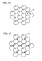
- FIG. 16 and FIG. 17 depict examples of “omni cell” and “three-sector cell” configurations respectively. In both cases, three frequencies, “f1” to “f3", are used, and different frequencies are allocated between adjacent cells and adjacent sectors.
- radio waves arrive from each of the base station apparatuses 100 of the six adjacent cells, so that there is a high possibility of interference.
- the directional antenna is used, so that radio waves are not received from base station apparatus in the diagonal upper-left direction, and to this extent there is less interference compared with the "omni cell” case.
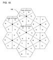
- FIG. 18 depicts an example of a "six-sector cell".
- the "six-sector cell” different frequencies are allocated to adjacent sectors, and the frequency utilization efficiency in each sector is "1/6".
- an occurrence of interference of the "sector cell” is less than of the "omni cell".
- the method of frequency allocation which utilizes the common frequency ( FIG. 14 ) is a method using the "omni cell”. By applying the frequency allocation method to the "sector cell", the occurrence of interference can be reduced.
- the frequency utilization efficiency of the "sector cell” is lower than the "omni cell".
- the frequency allocation utilization efficiency of the "omnicell” depicted in FIG. 14 is "1/2"
- the frequency allocation utilization efficiency of the "six-sector cell” system depicted in FIG. 18 is "1/6".
- a frequency allocation method in a wireless base station apparatus communicating wirelessly with a terminal apparatus, for dividing a cell that is a communication range of the wireless base station apparatus into six areas in a clockwise direction, and allocating a frequency to each of the divided sectors, includes: dividing the cell into an outer circle and an inner circle, wherein the outer circle is a range of the cell, and the inner circle is a range at a shorter distance from the wireless base station apparatus than the outer circle; allocating to a first terminal apparatus positioned in the outer circle of the sector, a frequency different from a frequency allocated to a second terminal apparatus positioned in (the inner circle of) an adjacent sector of the same cell, and different from a frequency allocated to a third terminal apparatus positioned in the outer circle of an adjacent sector of the adjacent cell; and allocating the frequency allocated to the first terminal apparatus to fourth and fifth terminal apparatuses positioned in the inner circle of two sectors respectively arranged two sectors away from the sector in which the first terminal apparatus is positioned.
- a frequency allocation method in a wireless base station apparatus for dividing a cell that is a communication range of the wireless base station apparatus communicating wirelessly with a terminal apparatus into six areas in a clockwise direction, and allocating a frequency to each of the six divided sectors, includes: receiving measurement result of communication quality with the wireless base station apparatus from the terminal apparatus, and determining position information indicating whether the terminal apparatus is positioned in an outer circle which is a range of the cell, or in an inner circle which is a range at a shorter distance from the wireless base station apparatus than the outer circle on the basis of the measurement result in a first table; selecting the frequency to be allocated to the terminal apparatus on the basis of the position information in a second table; selecting a transmission power value for the terminal apparatus on the basis of the position information in a third table; and transmitting and receiving data with the terminal apparatus at the selected frequency and transmission power value.
- FIG. 1 depicts an example of the configuration of a communication system
- FIG. 2 depicts an example of the configuration of a wireless base station apparatus
- FIG. 3 depicts an example of frequency arrangement
- FIG. 4A and FIG. 4B depict examples of transmission power values
- FIG. 5 is used to explain communication quality at the midpoint A
- FIG. 6 is used to explain communication quality at the midpoint B
- FIG. 7 is a flowchart depicting an example of operation of frequency allocation processing
- FIG. 8 depicts an example of an inner/outer circle judgment reference table
- FIG. 9 depicts an example of a frequency arrangement judgment reference table
- FIG. 10 depicts an example of a maximum transmission power reference table
- FIG. 11 is a flowchart depicting an example of operation of frequency allocation processing
- FIG. 12 depicts an example of a priority frequency selection reference table
- FIG. 13 depicts an example of frequency allocation of the prior art
- FIG. 14 depicts an example of frequency allocation of the prior art
- FIG. 15A to FIG. 15C depict examples of transmission power values
- FIG. 16 depicts an example of frequency allocation in an omnicell system
- FIG. 17 depicts an example of frequency allocation in a sector cell system
- FIG. 18 depicts an example of frequency allocation in a sector cell system.
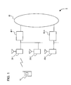
- FIG. 1 depicts an example of the configuration of a mobile communication system 1.
- the mobile communication system 1 includes a terminal apparatus 10, wireless base station apparatuses (hereafter “base station apparatuses”) 20-1 to 20-n, network connection apparatuses 40-1 to 40-m, and a communication network 60.
- base station apparatuses wireless base station apparatuses
- FIG. 1 depicts an example of the configuration of a mobile communication system 1.
- the mobile communication system 1 includes a terminal apparatus 10, wireless base station apparatuses (hereafter “base station apparatuses”) 20-1 to 20-n, network connection apparatuses 40-1 to 40-m, and a communication network 60.
- base station apparatuses wireless base station apparatuses
- the terminal apparatus 10 is for example a portable telephone, PDA (Personal Digital Assistant), or other portable information terminal.
- PDA Personal Digital Assistant
- the base station apparatuses 20-1 to 20-n are connected between the terminal apparatus 10 and the network connection apparatuses 40-1 to 40-m, and perform conversion, relaying, line management, communication control, and other processing between wireless lines and wire lines. Details are given below.
- the network connection apparatuses 40-1 to 40-m are interfaces between the communication network 60 and the base station apparatuses 20-1 to 20-n, and manage the states of the wire lines and terminal apparatus 10 and similar.
- each cell includes a configuration of a "sector cell", and the base station apparatuses 20-1 to 20-n include directional antennas.
- FIG. 2 depicts an example of the configuration of the base station apparatuses 20-1 to 20-n (hereafter, a "base station apparatus 20").
- the base station apparatus 20 includes a control unit 21, wireless transceiver unit 22, first to sixth antennas 23-1 to 23-6, measurement unit 24, wire connection unit 25, and storage unit 26.
- the control unit 21 is connected to the wireless transceiver unit 22, measurement unit 24, wire connection unit 25, and storage unit 26, and performs various control.
- the control unit 21 is described in detail below.
- the wireless transceiver unit 22 performs conversion between wireless signal and wire signal and similar, and sends transmission signal or receives reception signal by wireless communication.
- the wireless transceiver unit 22 further includes first to sixth sector RF units 22-1 to 22-6.
- the first to sixth sector RF units 22-1 to 22-6 are respectively connected to the first to sixth antennas 23-1 to 23-6, and output wireless signals of frequencies allocated in advance to the antennas 23-1 to 23-6 at prescribed transmission levels, under the control of the control unit 21.
- the first to sixth sector RF units 22-1 to 22-6 output wireless signals received by the antennas 23-1 to 23-6 from the terminal apparatus 10 to the control unit 21 and measurement unit 24.
- the first to sixth antennas 23-1 to 23-6 wirelessly transmit transmission signals from the first to sixth sector RF units 22-1 to 22-6 to the terminal apparatus 10, and receive wireless signals transmitted from the terminal apparatus 10 and output the signals to the first to sixth sector RF units 22-1 to 22-6.
- the first to sixth antennas 23-1 to 23-6 are antennas having so-called directionality, are each directed in a different direction, and transmit and receive wireless signals in the respective directions. Because the first to sixth antennas 23-1 to 23-6 are used, each such cell is called a "six-sector cell" including six sectors.
- the measurement unit 24 generates a common pilot signal or similar, outputs to the wireless transceiver unit 22 or similar, and measures the position of the subordinate terminal apparatus 10 by receiving the measurement result from the terminal apparatus 10.
- the wire connection unit 25 is connected with the network connection apparatuses 40-1 to 40-m, and outputs to the network connection apparatuses 40-1 to 40-m signals from the wireless transceiver unit 22 via the control unit 21, and outputs to the control unit 21 signals from the network connection apparatuses 40-1 to 40-m.
- the storage unit 26 stores various tables, including an inner outer circle judgment reference table, frequency arrangement reference table, maximum transmission power reference table, priority frequency selection reference table, and other tables.
- FIG. 3 depicts an example of frequency arrangement.
- One hexagon represents the cell range for one base station apparatus 20.
- Each cell has a so-called "six sector” configuration, and is divided into six sectors. Further, each cell is divided into areas of inner and outer circles, and different frequencies are arranged in sectors in the inner circles and outer circles.
- the frequencies arranged in the outer circle in each sector are different from the frequencies in the adjacent sectors of adjacent cells. Focusing on the cell of the base station apparatus 20A, frequencies "f1" to "f6" are arranged in order in the outer circle in the sectors 201 to 206 respectively.
- frequencies used in the outer circle are arranged within the circle in two sectors rotated 120° (in the two sectors which are two sectors away from the sector). Focusing on the cell of the base station apparatus 20A, the frequency "f1" allocated in the outer circle in sector 201 is arranged in the inner circle in the two sectors 203 and 205, shifted 120° in both directions in the same cell. When frequencies are similarly arranged in order in the inner circle, the frequency arrangement depicted in FIG. 3 results. When the terminal apparatus 10 is positioned in the inner circle and in the outer circle in each sector, frequencies are allocated as depicted in FIG. 3 .
- the frequency used in the outer circle can also be used in the inner circle.
- the frequency "f1" used in the outer circle can also be used in the inner circle.
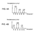
- FIG. 4A depicts the frequencies arranged in sector 217 of the base station apparatus 20C, and levels thereof;
- FIG. 4B depicts an example of frequencies arranged in sector 218 and levels thereof.
- the antenna 23-2 transmitting radio waves to sector 217 wirelessly transmits signals with the output level of the frequency "f2" at high level, and with the output level of the frequencies "f4" and “f6” at low level.
- the antenna 23-3 transmitting radio waves to sector 218 transmits at frequencies "f1", “f3" and "f5", and the transmission levels are respectively “low”, “high”, and "low”. By making a transmission level "high”, radio waves can be transmitted in the outer circle in the sector.
- FIG. 5 is used to explain communication quality at midpoint A; to make the explanation easy to understand, FIG. 5 is rotated 30° to the right relative to FIG. 3 .
- the midpoint A is the point equidistant from three base station apparatuses 20A, 20B, 20C, and radio waves from the antenna 23-1 of the base station apparatus 20A corresponding to sector 201 are desired waves, whereas radio waves from each of the antennas 23-1 to 23-6, corresponding to the sector 263 of base station apparatus 20B, the sector 220 of base station apparatus 20C, the sectors 221 and 225 of base station apparatus 20D, the sector 231 of base station apparatus 20E, the sector 241 of base station apparatus 20F, and the sectors 261 and 262 of base station apparatus 20G, are interference waves.
- midpoint A is positioned on the cell edge of base station 20A (or on the outside thereof), and is at the position with the harshest conditions for receiving interference waves from adjacent base station 20B and elsewhere. Hence by calculating the communication quality of midpoint A, it is possible to judge whether the frequency allocation depicted in FIG. 3 satisfies certain quality criteria.
- the powers received at midpoint A from each of the base station apparatuses 20A to 20G (the antennas 23-1 to 23-6 corresponding to each of the sectors 201 and similar) at frequency f1 (not including power received from sectors that can be ignored, as explained above), that is, the powers received from the sectors 201, 263, 220, 221, 231, 241, 261, 225, 262, are Pr1 to Pr9 (dBm)
- the transmitted powers from the base station apparatuses 20A to 20G in each of the above sectors are Pt1 to Pt9 (dBm)
- the power propagation losses from the base station apparatuses 20A to 20G to the midpoint A are L1 to L9 (dB).
- bracket [] denotes true values in dB.
- the distance from the base station apparatus 20A to the midpoint A is r
- the distance from the base station apparatuses 20E and 20F to the midpoint A is 2.65r.
- the amount of attenuation of transmitted power is proportional to the 3.5 power of the distance (attenuation factor 3.5 power law), and so the following equation obtains.
- Attenuation amount ratio 35 ⁇ log R / r ⁇ dB ⁇ 31
- the ratio of the transmitted ratio wave attenuation amount from the antennas 23-1 corresponding to the directions of sector 231 of base station apparatus 20E and sector 241 of base station apparatus 20F to the attenuation amount at distance r is 35log(2.65) ⁇ 14.8 (dB), and the following equation obtains.
- the ratio of the attenuation amount from the antennas 23-1 to 23-6 corresponding to the directions of sectors 221 and 225 of base station apparatus 20D and sectors 261 and 262 of base station apparatus 20G to the midpoint A, to the attenuation amount at distance r is 35log(2) ⁇ 10.5 (dB).
- the direction of each of the antennas 23-1 to 23-6 is inclined by 60° with respect to midpoint A, so that there is normally attenuation of approximately 13 (dB) on the basis of the properties of the antennas 23-1 to 23-6.
- the antennas 23-1 corresponding to the sector 201 of base station apparatus 20A, sector 221 of base station apparatus 20D, sector 231 of base station apparatus 20E, sector 241 of base station apparatus 20F, and sector 261 of base station apparatus 20G transmit radio waves to the outer circles at frequency "f1".
- the antennas 23-1 to 23-6 corresponding to the sector 263 of base station apparatus 20B, sector 220 of base station apparatus 20C, sector 225 of base station apparatus 20D, and sector 262 of base station apparatus 20G transmit radio waves to the inner circles at frequency "f1".
- the interference should be calculated at frequency f1, for example at the midpoint in the inner circle of sector 263 of base station apparatus 20B, correspondingly to the interference calculations at frequency f1 in the outer circles at midpoint A.
- the point for which interference is calculated is a midpoint in the inner circle in sector 201 of base station apparatus 20A, and the frequency considered is frequency f5, in order to make the relationship between sector and antenna direction more easy to understand.
- the results of calculations for frequency f5 are equal to calculations for f1 in sector 263.
- FIG. 6 is a figure used to explain communication quality at midpoint B, and is rotated 30° to the right relative to FIG. 3 in order to make the explanation easier to understand.
- radio wave from the antenna 23-1 of the base station apparatus 20A corresponding to the direction of sector 201 are desired wave
- radio waves from each of the antennas 23-1 to 23-6 corresponding to the sector 263 of base station apparatus 20B, the sector 220 of base station apparatus 20C, the sectors 221 and 225 of base station apparatus 20D, the sector 231 of base station apparatus 20E, the sector 241 of base station apparatus 20F, and the sectors 261 and 262 of base station apparatus 20G, are interference waves.
- the midpoint B is a point to judge whether a certain quality is satisfied at the inner and outer circle boundary, because the desired waves can be received at the midpoint B from the base station apparatus 20A within the sector, and radio wave with the high transmission power is interference transmitted from the adjacent base station apparatus 20C to the outer circle in sector 220 (at frequency f5) if sector is divided into the areas of inner circle and outer circle.
- the distance from the base station apparatus 20A to the midpoint B is 0.87rx (where r is the outer circle radius and x is the ratio of the radius of the inner circle to the radius of the outer circle when the quality within the inner circle is at a given level relative to the level at the outer circle radius r)
- the distance from the base station apparatus 20B and from the base station apparatus 20D to the midpoint B is 0.87(x 2 -2x+4)- 0.5
- L ⁇ 3 L ⁇ 1 + Lb
- the antennas 23-1 to 23-6 corresponding to the directions of sector 201 of base station apparatus 20A, sector 263 of base station apparatus 20B, sector 221 of base station apparatus 20D, sector 231 of base station apparatus 20E, sector 241 of base station apparatus 20F, and sectors 261 and 262 of base station apparatus 20G, transmit radio waves within the inner circles at frequency "f5".
- the antennas 23-5 corresponding to the directions of sector 220 of base station apparatus 20C and sector 225 of base station apparatus 20D transmit radio waves to the outer circles at frequency "f5".
- the transmission power ratio S to the inner and outer circles is "-5.6 dB”.
- the communication quality (2 dB) can be satisfied at midpoint B (in the inner circle in the sector 263 of base station apparatus 20B).
- the propagation loss that is, the attenuation amount conforms to equation (3), so that if the attenuation amount is 9.4 dB, the distance ratio R ⁇ 1.9.
- FIG. 7 is a flowchart of processing executed by the control unit 21 of the base station apparatus 20, and FIG. 8 to FIG. 10 are examples of tables used in the processing; FIG. 8 to FIG. 10 depict examples of the inner outer circle judgment reference table 251, frequency arrangement reference table 252, and maximum transmission power reference table 253, respectively.
- Each of the tables 251 to 253 is stored in the storage unit 26.
- the control unit 21 starts the processing (S20), and receives measurement results for the common channel signal (S21). Measurement results can for example be obtained by transmitting the common channel signal from each of the antennas 23-1 to 23-6 under control of the control unit 21, upon which the terminal apparatus 10 measures the interference ratio SIR for the common channel signal and transmits the results to the base station apparatus 20.
- the control unit 21 receives measurement results for the communication quality between the terminal apparatus 10 and the base station apparatus 20.
- the control unit 21 judges whether the terminal apparatus 10 exists within the outer circle or within the inner circle, on the basis of referencing the inner outer circle judgment reference table 251 (S22). As depicted in FIG. 8 , the control unit 21 judges the terminal apparatus 10 to be in the inner circle if the SIR measurement result is 10.9 (dB) or higher, and judges the terminal apparatus 10 to be in the outer circle if the SIR is lower than 10.9 (dB). Of course, this value of "10.9 dB" is one example, and another threshold value may be used.
- FIG. 9 is an example of the frequency arrangement reference table 252 for base station apparatus 20C.
- the frequency arrangement reference table 252 includes the number of sectors in which the terminal apparatus 10 is positioned, and the area (the inner circle or outer circle) in which the terminal apparatus 10 exists.
- the control unit 21 references the frequency arrangement reference table 252 using the information of the inner circle or outer circle obtained in S22 and the sector information received together with measurement results in S21.
- the control unit 21 references the maximum transmission power reference table 253, and selects the transmission power value, too, when the control unit 21 selects the frequency group.
- the maximum transmission power reference table 253 depicted in FIG. 10 is an example for base station apparatus 20C. As depicted in FIG. 10 , transmission power values are different for the inner and outer circles. Further, the base station maximum transmission power setting value is a power value of downlink-direction (the communication direction from the base station apparatus 20 to the terminal apparatus 10); the mobile station maximum transmission power setting value is a power value of the uplink direction (from the terminal apparatus 10 to the base station apparatus 20).
- control unit 21 transmits and receives data using the selected frequency and transmission power value (S24). And, the series of processing ends (S25). Of course, the control unit 21 transmits and receives data using another frequency and transmission power value by referencing the table 251 to 253 on the basis of the measurement results, if the terminal apparatus 10 moves from the inner circle to the outer circle or from one sector to another sector.
- the efficiency of the present embodiment is better than of the case of "six-sector cells" ( FIG. 18 ).
- the utilization efficiency of the case using the common frequency ( FIG. 14 ) and the case of the present embodiment is "1/2" in both cases
- the interference of the present embodiment is reduced, compared with the case of "omni cell” ( FIG. 14 ), because each of the sectors and the cells of the present embodiment uses the "sector cell".
- the base station apparatus with high efficiency of frequency utilization can be provided.
- the base station apparatus for which interference from adjacent cells and adjacent sectors is reduced can be provided.
- the frequency allocated to the outer circle can also be used for communication in the inner circle in each sector.
- the frequency to allocate to the outer circle is exhausted if the frequency to allocate to the outer circle is too allocated to the inner circle.
- such the situation is avoided by providing a limit on the frequencies that can be used in the inner circle.
- FIG. 11 depicts a flowchart of processing in the one embodiment
- FIG. 12 depicts an example of a priority frequency selection reference table 254.
- the priority frequency selection reference table 254 is stored in the storage unit 26.
- Operation in the one embodiment is performed when the frequency group is selected by the control unit 21 from the frequency arrangement reference table 252 (S23 in FIG. 5 ).
- the control unit 21 allocates frequencies to the inner circle and outer circle according to the frequency arrangement reference table 252 (S231).
- control unit 21 judges whether frequencies which can be used only in the inner circle can be allocated (S232).
- the control unit 21 references the priority frequency selection reference table 254 and makes the judgment. Specifically, the judgment is performed as follows.
- control unit 21 references the priority frequency selection reference table 254, and determines whether the frequency allocated to the inner circle is a "low priority” or "high priority". When the frequency is the "high priority”, the "frequency for use only in the inner circle” is allocated without modification (Yes in S232, S233).
- the control unit 21 changes the allocation from the "low priority” frequency to the "high priority” frequency, if the frequency allocated to the inner circle is the “low frequency” and there is an unused "high priority” frequency (Yes in S232, S233).
- the "low priority” frequency is used without modification if there is no unused "high priority” frequency (No in S232, S234).
- the "frequency which can be used only in the inner circle” is allocated priority about the frequency allocated to the inner circle, and the "frequency which can also be used in the outer circle” is allocated if the number of the terminal apparatuses existing in the inner circle is greater than the threshold value and the "frequency which can be used only in the inner circle” cannot be allocated.
- a frequency allocation method in a wireless base station device with high frequency allocation efficiency, and such a wireless base station device, can be provided.
- a frequency allocation method which reduces interference from adjacent cells and adjacent sectors can be provided.
Landscapes
- Engineering & Computer Science (AREA)
- Computer Networks & Wireless Communication (AREA)
- Signal Processing (AREA)
- Mobile Radio Communication Systems (AREA)
Abstract
Description
- The present invention is related to a frequency allocation method in a wireless base station apparatus, and to a wireless base station apparatus.
- In the prior art, communication methods such as FDMA (Frequency Division Multiple Access) and OFDMA (Orthogonal Frequency Division Multiple Access) have employed a method of dividing the frequencies allocated to the entire system and allocating different frequencies to adjacent cells, in order to avoid interference between adjacent cells (see for example Japanese Laid-open Patent Publication No.
2004-159345 -
FIG. 13 is used to explain the frequency allocation method. As depicted in the figure, in the method, for example three cells (cells #A to #C) are allocated different frequencies (f1 to f3). Near cell boundaries, two terminal apparatuses positioned in different cells use different frequencies, so that there are no problems with interference, and good-quality communication with a base station apparatuses is possible. -
FIG. 14 andFIG. 15A to FIG. 15C depict an example of another method of frequency allocation described in the above Japanese Laid-open Patent Publication No.2004-159345 FIG. 13 and similar, a common frequency (f4) is allocated in regions near the base station in each cell, and in regions near boundaries with adjacent cells, frequencies which are different from those of adjacent cells (f1 to f3) are allocated. - In the frequency allocation method in which different frequencies are allocated to adjacent cells (
FIG. 13 ), the frequency utilization efficiency in each cell is "1/3" of the overall frequency band. On the other hand, in the frequency allocation method in which different frequencies are allocated to adjacent cells while using the common frequency (FIG. 14 and elsewhere), the frequency utilization efficiency is "2/4 = 1/2". The frequency efficiency of frequency allocation using the common frequency is better than that of frequency allocation not using the common frequency. - On the other hand, cell configuration methods include "omni cell" and "sector cell" methods. The "omni cell" is a cell using a non directional antenna in the base station apparatus. A "sector cell" is a cell using a directional antenna.
FIG. 16 and FIG. 17 depict examples of "omni cell" and "three-sector cell" configurations respectively. In both cases, three frequencies, "f1" to "f3", are used, and different frequencies are allocated between adjacent cells and adjacent sectors. - Focusing on the cell and sector to which the frequency "f1" is allocated, in the "omni cell" (
FIG. 16 ), radio waves arrive from each of thebase station apparatuses 100 of the six adjacent cells, so that there is a high possibility of interference. On the other hand in the "three sector cell" (FIG. 17 ), the directional antenna is used, so that radio waves are not received from base station apparatus in the diagonal upper-left direction, and to this extent there is less interference compared with the "omni cell" case. -
FIG. 18 depicts an example of a "six-sector cell". In the "six-sector cell", different frequencies are allocated to adjacent sectors, and the frequency utilization efficiency in each sector is "1/6". - As explained above, an occurrence of interference of the "sector cell" is less than of the "omni cell". The method of frequency allocation which utilizes the common frequency (
FIG. 14 ) is a method using the "omni cell". By applying the frequency allocation method to the "sector cell", the occurrence of interference can be reduced. - However, the frequency utilization efficiency of the "sector cell" is lower than the "omni cell". For example, the frequency allocation utilization efficiency of the "omnicell" depicted in
FIG. 14 is "1/2", but the frequency allocation utilization efficiency of the "six-sector cell" system depicted inFIG. 18 is "1/6". - Accordingly, it is desirable to provide a frequency allocation method in a wireless base station apparatus, and a wireless base station apparatus, with high frequency utilization efficiency.
- It is also desirable to provide a frequency allocation method which reduces interference with adjacent cells and adjacent sectors.
- According to an aspect of the invention, a frequency allocation method, in a wireless base station apparatus communicating wirelessly with a terminal apparatus, for dividing a cell that is a communication range of the wireless base station apparatus into six areas in a clockwise direction, and allocating a frequency to each of the divided sectors, includes: dividing the cell into an outer circle and an inner circle, wherein the outer circle is a range of the cell, and the inner circle is a range at a shorter distance from the wireless base station apparatus than the outer circle; allocating to a first terminal apparatus positioned in the outer circle of the sector, a frequency different from a frequency allocated to a second terminal apparatus positioned in (the inner circle of) an adjacent sector of the same cell, and different from a frequency allocated to a third terminal apparatus positioned in the outer circle of an adjacent sector of the adjacent cell; and allocating the frequency allocated to the first terminal apparatus to fourth and fifth terminal apparatuses positioned in the inner circle of two sectors respectively arranged two sectors away from the sector in which the first terminal apparatus is positioned.
- According to an aspect of the invention, a frequency allocation method in a wireless base station apparatus for dividing a cell that is a communication range of the wireless base station apparatus communicating wirelessly with a terminal apparatus into six areas in a clockwise direction, and allocating a frequency to each of the six divided sectors, includes: receiving measurement result of communication quality with the wireless base station apparatus from the terminal apparatus, and determining position information indicating whether the terminal apparatus is positioned in an outer circle which is a range of the cell, or in an inner circle which is a range at a shorter distance from the wireless base station apparatus than the outer circle on the basis of the measurement result in a first table; selecting the frequency to be allocated to the terminal apparatus on the basis of the position information in a second table; selecting a transmission power value for the terminal apparatus on the basis of the position information in a third table; and transmitting and receiving data with the terminal apparatus at the selected frequency and transmission power value.
- The advantages of the invention will be realized and attained by means of the elements and combinations particularly pointed out in the claims.
- It is to be understood that both the foregoing general description and the following detailed description are exemplary and explanatory and are not restrictive of the invention, as claimed.
Reference is made, by way of example only, to the accompanying drawings in which: -
FIG. 1 depicts an example of the configuration of a communication system; -
FIG. 2 depicts an example of the configuration of a wireless base station apparatus; -
FIG. 3 depicts an example of frequency arrangement; -
FIG. 4A and FIG. 4B depict examples of transmission power values; -
FIG. 5 is used to explain communication quality at the midpoint A; -
FIG. 6 is used to explain communication quality at the midpoint B; -
FIG. 7 is a flowchart depicting an example of operation of frequency allocation processing; -
FIG. 8 depicts an example of an inner/outer circle judgment reference table; -
FIG. 9 depicts an example of a frequency arrangement judgment reference table; -
FIG. 10 depicts an example of a maximum transmission power reference table; -
FIG. 11 is a flowchart depicting an example of operation of frequency allocation processing; -
FIG. 12 depicts an example of a priority frequency selection reference table; -
FIG. 13 depicts an example of frequency allocation of the prior art; -
FIG. 14 depicts an example of frequency allocation of the prior art; -
FIG. 15A to FIG. 15C depict examples of transmission power values; -
FIG. 16 depicts an example of frequency allocation in an omnicell system; -
FIG. 17 depicts an example of frequency allocation in a sector cell system; and -
FIG. 18 depicts an example of frequency allocation in a sector cell system. - Preferred embodiments of the present invention will be explained with reference to accompanying drawings.
-
FIG. 1 depicts an example of the configuration of amobile communication system 1. Themobile communication system 1 includes aterminal apparatus 10, wireless base station apparatuses (hereafter "base station apparatuses") 20-1 to 20-n, network connection apparatuses 40-1 to 40-m, and acommunication network 60. - The
terminal apparatus 10 is for example a portable telephone, PDA (Personal Digital Assistant), or other portable information terminal. - The base station apparatuses 20-1 to 20-n are connected between the
terminal apparatus 10 and the network connection apparatuses 40-1 to 40-m, and perform conversion, relaying, line management, communication control, and other processing between wireless lines and wire lines. Details are given below. - The network connection apparatuses 40-1 to 40-m are interfaces between the
communication network 60 and the base station apparatuses 20-1 to 20-n, and manage the states of the wire lines andterminal apparatus 10 and similar. - In the
mobile communication system 1, theterminal apparatus 10 communicates wirelessly with the base station apparatuses 20-1 to 20-n which form the cells which are the ranges over which communication with the base station apparatuses 20-1 to 20-n is possible, while theterminal apparatus 10 moves through the cells. In the embodiment, each cell includes a configuration of a "sector cell", and the base station apparatuses 20-1 to 20-n include directional antennas. -
FIG. 2 depicts an example of the configuration of the base station apparatuses 20-1 to 20-n (hereafter, a "base station apparatus 20"). - The
base station apparatus 20 includes acontrol unit 21,wireless transceiver unit 22, first to sixth antennas 23-1 to 23-6,measurement unit 24,wire connection unit 25, andstorage unit 26. - The
control unit 21 is connected to thewireless transceiver unit 22,measurement unit 24,wire connection unit 25, andstorage unit 26, and performs various control. Thecontrol unit 21 is described in detail below. - The
wireless transceiver unit 22 performs conversion between wireless signal and wire signal and similar, and sends transmission signal or receives reception signal by wireless communication. Thewireless transceiver unit 22 further includes first to sixth sector RF units 22-1 to 22-6. The first to sixth sector RF units 22-1 to 22-6 are respectively connected to the first to sixth antennas 23-1 to 23-6, and output wireless signals of frequencies allocated in advance to the antennas 23-1 to 23-6 at prescribed transmission levels, under the control of thecontrol unit 21. The first to sixth sector RF units 22-1 to 22-6 output wireless signals received by the antennas 23-1 to 23-6 from theterminal apparatus 10 to thecontrol unit 21 andmeasurement unit 24. - The first to sixth antennas 23-1 to 23-6 wirelessly transmit transmission signals from the first to sixth sector RF units 22-1 to 22-6 to the
terminal apparatus 10, and receive wireless signals transmitted from theterminal apparatus 10 and output the signals to the first to sixth sector RF units 22-1 to 22-6. The first to sixth antennas 23-1 to 23-6 are antennas having so-called directionality, are each directed in a different direction, and transmit and receive wireless signals in the respective directions. Because the first to sixth antennas 23-1 to 23-6 are used, each such cell is called a "six-sector cell" including six sectors. - The
measurement unit 24 generates a common pilot signal or similar, outputs to thewireless transceiver unit 22 or similar, and measures the position of the subordinateterminal apparatus 10 by receiving the measurement result from theterminal apparatus 10. - The
wire connection unit 25 is connected with the network connection apparatuses 40-1 to 40-m, and outputs to the network connection apparatuses 40-1 to 40-m signals from thewireless transceiver unit 22 via thecontrol unit 21, and outputs to thecontrol unit 21 signals from the network connection apparatuses 40-1 to 40-m. - The
storage unit 26 stores various tables, including an inner outer circle judgment reference table, frequency arrangement reference table, maximum transmission power reference table, priority frequency selection reference table, and other tables. - Next, an example of frequency arrangement in the embodiment is explained.
FIG. 3 depicts an example of frequency arrangement. One hexagon represents the cell range for onebase station apparatus 20. Each cell has a so-called "six sector" configuration, and is divided into six sectors. Further, each cell is divided into areas of inner and outer circles, and different frequencies are arranged in sectors in the inner circles and outer circles. In the frequency arrangement depicted inFIG. 3 , the frequencies arranged in the outer circle in each sector are different from the frequencies in the adjacent sectors of adjacent cells. Focusing on the cell of thebase station apparatus 20A, frequencies "f1" to "f6" are arranged in order in the outer circle in thesectors 201 to 206 respectively. And, in the same cell, frequencies used in the outer circle are arranged within the circle in two sectors rotated 120° (in the two sectors which are two sectors away from the sector). Focusing on the cell of thebase station apparatus 20A, the frequency "f1" allocated in the outer circle insector 201 is arranged in the inner circle in the twosectors FIG. 3 results. When theterminal apparatus 10 is positioned in the inner circle and in the outer circle in each sector, frequencies are allocated as depicted inFIG. 3 . - In the frequency arrangement of the embodiment, the frequency used in the outer circle can also be used in the inner circle. For example, in
sector 201 of thebase station apparatus 20A, the frequency "f1" used in the outer circle can also be used in the inner circle. -
FIG. 4A depicts the frequencies arranged insector 217 of thebase station apparatus 20C, and levels thereof;FIG. 4B depicts an example of frequencies arranged insector 218 and levels thereof. As depicted inFIG. 4A , the antenna 23-2 transmitting radio waves tosector 217 wirelessly transmits signals with the output level of the frequency "f2" at high level, and with the output level of the frequencies "f4" and "f6" at low level. On the other hand, the antenna 23-3 transmitting radio waves tosector 218 transmits at frequencies "f1", "f3" and "f5", and the transmission levels are respectively "low", "high", and "low". By making a transmission level "high", radio waves can be transmitted in the outer circle in the sector. - Next, communication quality for the frequency arrangement depicted in
FIG. 3 is explained. The midpoints A and B depicted inFIG. 3 are used as evaluation points, and communication quality at these points is explained. - First, communication quality at midpoint A is explained.
FIG. 5 is used to explain communication quality at midpoint A; to make the explanation easy to understand,FIG. 5 is rotated 30° to the right relative toFIG. 3 . - Here, focusing on the frequency f1, the midpoint A is the point equidistant from three
base station apparatuses base station apparatus 20A corresponding tosector 201 are desired waves, whereas radio waves from each of the antennas 23-1 to 23-6, corresponding to thesector 263 ofbase station apparatus 20B, thesector 220 ofbase station apparatus 20C, thesectors base station apparatus 20D, thesector 231 ofbase station apparatus 20E, thesector 241 ofbase station apparatus 20F, and thesectors base station apparatus 20G, are interference waves. - Thus the midpoint A is positioned on the cell edge of
base station 20A (or on the outside thereof), and is at the position with the harshest conditions for receiving interference waves fromadjacent base station 20B and elsewhere. Hence by calculating the communication quality of midpoint A, it is possible to judge whether the frequency allocation depicted inFIG. 3 satisfies certain quality criteria. - Here, considering the directionality of the antennas in each sector, interference from sectors the antenna direction of which is 90° or more at variance from the direction to the midpoint A is ignored (sectors indicated by dotted-line shading in
FIG. 5 ). For example,sector 203 ofbase station 20A andsector 218 ofbase station 20C also use frequency f1, but the directions of these antennas are directed away from the midpoint A, and the so-called front-back ratio is approximately 25 dB (there is attenuation of approximately 25 dB = 1/300 relative to the gain in the antenna direction), and so such interference can be ignored. Similarly hereafter, when the antenna direction is at variance by 90° or more from the observation point (midpoint A, midpoint B, and so on), this interference can be ignored in interference calculations. - The powers received at midpoint A from each of the
base station apparatuses 20A to 20G (the antennas 23-1 to 23-6 corresponding to each of thesectors 201 and similar) at frequency f1 (not including power received from sectors that can be ignored, as explained above), that is, the powers received from thesectors base station apparatuses 20A to 20G in each of the above sectors are Pt1 to Pt9 (dBm), and the power propagation losses from thebase station apparatuses 20A to 20G to the midpoint A are L1 to L9 (dB). The signal-interference ratio SIR for frequency f1 at midpoint A is given by
Modifying equation (1) gives:
- Here, the midpoint A is equidistant from the
base station apparatuses base station apparatuses - Further, if the distance from the
base station apparatus 20A to the midpoint A is r, the distance from thebase station apparatuses -


- Hence, the ratio of the transmitted ratio wave attenuation amount from the antennas 23-1 corresponding to the directions of
sector 231 ofbase station apparatus 20E andsector 241 ofbase station apparatus 20F to the attenuation amount at distance r is 35log(2.65) ≈ 14.8 (dB), and the following equation obtains.
- Further, because the distance from the
base station apparatuses sectors base station apparatus 20D andsectors base station apparatus 20G to the midpoint A, to the attenuation amount at distance r, is 35log(2) ≈ 10.5 (dB). However, in this case, the direction of each of the antennas 23-1 to 23-6 is inclined by 60° with respect to midpoint A, so that there is normally attenuation of approximately 13 (dB) on the basis of the properties of the antennas 23-1 to 23-6. Hence the following obtains.
- Further, the antennas 23-1 corresponding to the
sector 201 ofbase station apparatus 20A,sector 221 ofbase station apparatus 20D,sector 231 ofbase station apparatus 20E,sector 241 ofbase station apparatus 20F, andsector 261 ofbase station apparatus 20G transmit radio waves to the outer circles at frequency "f1". - On the other hand, the antennas 23-1 to 23-6 corresponding to the
sector 263 ofbase station apparatus 20B,sector 220 ofbase station apparatus 20C,sector 225 ofbase station apparatus 20D, andsector 262 ofbase station apparatus 20G transmit radio waves to the inner circles at frequency "f1". - Here, if the ratio of transmission powers in the inner and outer circles is S, then the following obtain.


- Substituting all of equations (4) to (7) into equation (2) gives:

- Proceeding with calculations while noting that the bracket [] denotes true value in dB, on the right-hand side of equation (8), the [Pt1-L1] is canceled in the numerator and denominator. And, by substituting SIR = 2 (dB) into equation (8), S ≈ -5.6 (dB) is obtained.
- That is, with respect to the communication quality at midpoint A, by setting the transmission power in the inner circles approximately "5.6 dB" lower than the transmission power in the outer circles for each of the
base station apparatuses 20A to 20G, a certain quality at midpoint A (for example, SIR = 2 dB) can be satisfied. - Next, communication quality at the midpoint B is explained. The interference should be calculated at frequency f1, for example at the midpoint in the inner circle of
sector 263 ofbase station apparatus 20B, correspondingly to the interference calculations at frequency f1 in the outer circles at midpoint A. However, the point for which interference is calculated is a midpoint in the inner circle insector 201 ofbase station apparatus 20A, and the frequency considered is frequency f5, in order to make the relationship between sector and antenna direction more easy to understand. The results of calculations for frequency f5 are equal to calculations for f1 insector 263. -
FIG. 6 is a figure used to explain communication quality at midpoint B, and is rotated 30° to the right relative toFIG. 3 in order to make the explanation easier to understand. - In this case, radio wave from the antenna 23-1 of the
base station apparatus 20A corresponding to the direction ofsector 201 are desired wave, whereas radio waves from each of the antennas 23-1 to 23-6, corresponding to thesector 263 ofbase station apparatus 20B, thesector 220 ofbase station apparatus 20C, thesectors base station apparatus 20D, thesector 231 ofbase station apparatus 20E, thesector 241 ofbase station apparatus 20F, and thesectors base station apparatus 20G, are interference waves. In addition to the above sectors, there also exist other sectors which use the frequency f5, but due to the antenna direction and the antenna directionality, these interference powers can be ignored. - The midpoint B is a point to judge whether a certain quality is satisfied at the inner and outer circle boundary, because the desired waves can be received at the midpoint B from the
base station apparatus 20A within the sector, and radio wave with the high transmission power is interference transmitted from the adjacentbase station apparatus 20C to the outer circle in sector 220 (at frequency f5) if sector is divided into the areas of inner circle and outer circle. - The signal-interference ratio SIR for frequency f5 at midpoint B is

- If the distance from the
base station apparatus 20A to the midpoint B is 0.87rx (where r is the outer circle radius and x is the ratio of the radius of the inner circle to the radius of the outer circle when the quality within the inner circle is at a given level relative to the level at the outer circle radius r), the distance from thebase station apparatus 20B and from thebase station apparatus 20D to the midpoint B is 0.87(x2-2x+4)-0.5, so that the ratio of the attenuation from thebase station apparatus 20A to the midpoint B to the attenuation from thebase station apparatuses base station apparatus 20D forsector 221 is inclined 60° or more with respect to the midpoint B, there is normally attenuation of approximately 13 dB on the basis of the antenna properties. Hence,

- The ratio of the attenuation from the
base station apparatus 20A to the midpoint B to the attenuation from thebase station apparatus 20C to the midpoint B is 35log{(2-x)/x} = Lb (dB), and so the following obtains.
- The ratio of the attenuation from the
base station apparatus 20A to the midpoint B to the attenuation from thebase station apparatus 20E and thebase station apparatus 20G to the midpoint B is 35log{(x2+2x+4)-0.5/x} - Lc (dB). Because the antenna direction in thebase station apparatus 20G ofsector 261 is inclined 60° or more with respect to the midpoint B, there is normally attenuation of approximately 13 dB on the basis of the antenna properties.
Hence,

- The ratio of the attenuation from the
base station apparatus 20A to the midpoint B to the attenuation from thebase station apparatus 20F to the midpoint B is 35log{(3-x)/x} = Ld (dB), and so the following obtains.
- The antennas 23-1 to 23-6 corresponding to the directions of
sector 201 ofbase station apparatus 20A,sector 263 ofbase station apparatus 20B,sector 221 ofbase station apparatus 20D,sector 231 ofbase station apparatus 20E,sector 241 ofbase station apparatus 20F, andsectors base station apparatus 20G, transmit radio waves within the inner circles at frequency "f5". - On the other hand, the antennas 23-5 corresponding to the directions of
sector 220 ofbase station apparatus 20C andsector 225 ofbase station apparatus 20D transmit radio waves to the outer circles at frequency "f5". When the transmission power ratio S to the inner and outer circles is "-5.6 dB", the following obtain.

- Here, substituting equations (101) to (108) into equation (9) gives:

- In the equation (11), upon determining the value of x for which SIR = 2 dB, x = 0.70 is obtained (if the outer circle radius for the
base station apparatus 20A is 1, the radius of the inner circle is 0.7), and Lb = 35log{(2-0.70)/0.70} = 9.4 dB is obtained. - That is, if the ratio of propagation losses between
base station apparatus 20A and midpoint B, and betweenbase station apparatus 20B and midpoint B is 9.4 dB, then the communication quality (2 dB) can be satisfied at midpoint B (in the inner circle in thesector 263 ofbase station apparatus 20B). Here, the propagation loss, that is, the attenuation amount conforms to equation (3), so that if the attenuation amount is 9.4 dB, the distance ratio R ≈ 1.9. - That is, with respect to the communication quality at midpoint B, if the transmission power ratio between the inner circle and outer circle is approximately 5.6 dB, and the ratio of distances between the
base station apparatus 20A and midpoint B and between thebase station apparatus 20B and midpoint B is approximately 1.9, then the certain quality (for example, SIR = 2 dB) can be satisfied. - Next, operation is explained when allocating the frequencies depicted in
FIG. 3 to the terminal apparatus.FIG. 7 is a flowchart of processing executed by thecontrol unit 21 of thebase station apparatus 20, andFIG. 8 to FIG. 10 are examples of tables used in the processing;FIG. 8 to FIG. 10 depict examples of the inner outer circle judgment reference table 251, frequency arrangement reference table 252, and maximum transmission power reference table 253, respectively. Each of the tables 251 to 253 is stored in thestorage unit 26. - As depicted in
FIG. 7 , thecontrol unit 21 starts the processing (S20), and receives measurement results for the common channel signal (S21). Measurement results can for example be obtained by transmitting the common channel signal from each of the antennas 23-1 to 23-6 under control of thecontrol unit 21, upon which theterminal apparatus 10 measures the interference ratio SIR for the common channel signal and transmits the results to thebase station apparatus 20. Thecontrol unit 21 receives measurement results for the communication quality between theterminal apparatus 10 and thebase station apparatus 20. - Next, the
control unit 21 judges whether theterminal apparatus 10 exists within the outer circle or within the inner circle, on the basis of referencing the inner outer circle judgment reference table 251 (S22). As depicted inFIG. 8 , thecontrol unit 21 judges theterminal apparatus 10 to be in the inner circle if the SIR measurement result is 10.9 (dB) or higher, and judges theterminal apparatus 10 to be in the outer circle if the SIR is lower than 10.9 (dB). Of course, this value of "10.9 dB" is one example, and another threshold value may be used. - Next, the
control unit 21 selects the frequency group from the reference arrangement reference table 252 (S23).FIG. 9 is an example of the frequency arrangement reference table 252 forbase station apparatus 20C. The frequency arrangement reference table 252 includes the number of sectors in which theterminal apparatus 10 is positioned, and the area (the inner circle or outer circle) in which theterminal apparatus 10 exists. Thecontrol unit 21 references the frequency arrangement reference table 252 using the information of the inner circle or outer circle obtained in S22 and the sector information received together with measurement results in S21. - Here, sector information is explained. First, common pilot signals are transmitted under control of the
control unit 21 from the antennas 23-1 to 23-6 of thebase station apparatus 20 corresponding to each sector. At this time, the SIR and similar for the common pilot signals are measured by theterminal apparatus 10 existing in the sectors, and the results are transmitted to thebase station apparatus 20; these measurement results are received by one among the antennas 23-1 to 23-6 (or the sector RF units 22-1 to 22-6). The directions of the antennas 23-1 to 23-6 are fixed, and the corresponding sectors are also determined. Hence the information of the sector in which theterminal apparatus 10 is positioned can be obtained from which of the antennas 23-1 to 23-6 has received the measurement results. The sector information is output to thecontrol unit 21 from for example the sector RF unit 22-1 to 22-6 which has received the measurement results. - The
control unit 21 references the maximum transmission power reference table 253, and selects the transmission power value, too, when thecontrol unit 21 selects the frequency group. The maximum transmission power reference table 253 depicted inFIG. 10 is an example forbase station apparatus 20C. As depicted inFIG. 10 , transmission power values are different for the inner and outer circles. Further, the base station maximum transmission power setting value is a power value of downlink-direction (the communication direction from thebase station apparatus 20 to the terminal apparatus 10); the mobile station maximum transmission power setting value is a power value of the uplink direction (from theterminal apparatus 10 to the base station apparatus 20). - Returning to
FIG. 7 , thecontrol unit 21 transmits and receives data using the selected frequency and transmission power value (S24). And, the series of processing ends (S25). Of course, thecontrol unit 21 transmits and receives data using another frequency and transmission power value by referencing the table 251 to 253 on the basis of the measurement results, if theterminal apparatus 10 moves from the inner circle to the outer circle or from one sector to another sector. - As depicted in
FIG. 3 , the frequency utilization efficiency in each sector for each of thebase station apparatuses 20A to 20G is "3/6 = 1/2". Hence, the efficiency of the present embodiment is better than of the case of "six-sector cells" (FIG. 18 ). While the utilization efficiency of the case using the common frequency (FIG. 14 ) and the case of the present embodiment is "1/2" in both cases, the interference of the present embodiment is reduced, compared with the case of "omni cell" (FIG. 14 ), because each of the sectors and the cells of the present embodiment uses the "sector cell". Hence, in the present embodiment, the base station apparatus with high efficiency of frequency utilization can be provided. Moreover, in the present embodiment, the base station apparatus for which interference from adjacent cells and adjacent sectors is reduced can be provided. - Next, another embodiment is explained. In the above-described embodiment, the frequency allocated to the outer circle can also be used for communication in the inner circle in each sector. However, when the number of
terminal apparatuses 10 is extremely big in the inner circle for example, it is a case that the frequency to allocate to the outer circle is exhausted if the frequency to allocate to the outer circle is too allocated to the inner circle.
Hence, in one embodiment, such the situation is avoided by providing a limit on the frequencies that can be used in the inner circle. -
FIG. 11 depicts a flowchart of processing in the one embodiment, andFIG. 12 depicts an example of a priority frequency selection reference table 254. The priority frequency selection reference table 254 is stored in thestorage unit 26. - Operation in the one embodiment is performed when the frequency group is selected by the
control unit 21 from the frequency arrangement reference table 252 (S23 inFIG. 5 ). Thecontrol unit 21 allocates frequencies to the inner circle and outer circle according to the frequency arrangement reference table 252 (S231). - Next, the
control unit 21 judges whether frequencies which can be used only in the inner circle can be allocated (S232). Thecontrol unit 21 references the priority frequency selection reference table 254 and makes the judgment. Specifically, the judgment is performed as follows. - That is, the
control unit 21 references the priority frequency selection reference table 254, and determines whether the frequency allocated to the inner circle is a "low priority" or "high priority". When the frequency is the "high priority", the "frequency for use only in the inner circle" is allocated without modification (Yes in S232, S233). - The
control unit 21 changes the allocation from the "low priority" frequency to the "high priority" frequency, if the frequency allocated to the inner circle is the "low frequency" and there is an unused "high priority" frequency (Yes in S232, S233). The "low priority" frequency is used without modification if there is no unused "high priority" frequency (No in S232, S234). - For example, when the frequency allocated to the inner circle is "f1", upon referencing the priority frequency selection reference table 254, this frequency is found to be "low priority", but the frequency "f3" or "f5" is allocated if there are unused resources which are "f3" and "f5" of the "high priority" frequency.
- That is, in the one embodiment, the "frequency which can be used only in the inner circle" is allocated priority about the frequency allocated to the inner circle, and the "frequency which can also be used in the outer circle" is allocated if the number of the terminal apparatuses existing in the inner circle is greater than the threshold value and the "frequency which can be used only in the inner circle" cannot be allocated. By this processing, the problem in which too frequency which is to be allocated in the outer circle is used in the inner circle and are exhausted, can be resolved.
- A frequency allocation method in a wireless base station device with high frequency allocation efficiency, and such a wireless base station device, can be provided. Moreover, a frequency allocation method which reduces interference from adjacent cells and adjacent sectors can be provided.
- All examples and conditional language recited herein are intended for pedagogical purposes to aid the reader in understanding the invention and the concepts contributed by the inventor to furthering the art, and are to be construed as being without limitation to such specifically recited examples and conditions, nor does the organization of such examples in the specification relate to a depicting of the superiority and inferiority of the invention. Although the embodiment(s) of the present inventions have been described in detail, it should be understood that the various changes, substitutions, and alterations could be made hereto without departing from the scope of the claims.
Claims (11)
- A frequency allocation method, in a wireless base station apparatus communicating wirelessly with a terminal apparatus, for dividing a cell that is a communication range of the wireless base station apparatus into six areas in a clockwise direction, and allocating a frequency to each of the divided sectors, the method comprising:dividing the cell into an outer circle and an inner circle, wherein the outer circle is a range of the cell, and the inner circle is a range at a shorter distance from the wireless base station apparatus than the outer circle;allocating to a first terminal apparatus positioned in the outer circle of the sector, a frequency different from a frequency allocated to a second terminal apparatus positioned in an adjacent sector of the same cell, and the frequency different from a frequency allocated to a third terminal apparatus positioned in the outer circle of an adjacent sector of the adjacent cell; andallocating the frequency allocated to the first terminal apparatus to fourth and fifth terminal apparatus positioned in the inner circle of two sectors respectively arranged two sectors away from the sector in which the first terminal apparatus is positioned.
- The frequency allocation method according to Claim 1, further comprising reducing a transmission power to the fourth and fifth terminal apparatus positioned in the inner circle by 5.6 dB from the transmission power to the first terminal apparatus positioned in the outer circle, and transmitting data to the first, or to the fourth and fifth terminal apparatus.
- The frequency allocation method according to Claim 2, wherein the inner circle is divided such that the ratio of the distance from the wireless base station apparatus to the inner circle, to the distance from a wireless base station apparatus of the adjacent cell to the inner circle, is 1.9, when the cell is divided into the outer circle and the inner circle.
- The frequency allocation method according to Claim 1, wherein the frequency allocated to the first terminal apparatus is allocated to the fourth and fifth terminal apparatus with precedence when the frequency is allocated to the fourth and fifth terminal apparatus, and a frequency to be allocated to a sixth terminal apparatus positioned in the outer circle of the same sector as the inner circle in which the fourth or fifth terminal apparatus is positioned is allocated to the fourth or fifth terminal apparatus when the number of the fourth or fifth terminal apparatuses exceeds a first threshold and the frequency to be allocated to the fourth and fifth terminal apparatus can not be allocated.
- A frequency allocation method in a wireless base station apparatus for dividing a cell that is a communication range of the wireless base station apparatus communicating wirelessly with a terminal apparatus into six areas in a clockwise direction, and allocating a frequency to each of the six divided sectors, the method comprising:receiving measurement result of communication quality with the wireless base station apparatus from the terminal apparatus, and determining position information indicating whether the terminal apparatus is positioned in an outer circle which is a range of the cell, or in an inner circle which is a range at a shorter distance from the wireless base station apparatus than the outer circle on the basis of the measurement result in a first table;selecting the frequency to be allocated to the terminal apparatus on the basis of the position information in a second table;selecting a transmission power value for the terminal apparatus on the basis of the position information in a third table; andtransmitting and receiving data with the terminal apparatus at the selected frequency and transmission power value.
- The frequency allocation method according to Claim 5, wherein the wireless base station apparatus reduces the power of transmission to the terminal apparatuses positioned in the inner circle by 5.6 dB from the power of transmission to the terminal apparatuses positioned in the outer circle, and transmits the data, when the wireless base station transmits data to the terminal apparatuses at the selected frequency and transmission power value.
- The frequency allocation method according to Claim 6, wherein the inner circles are positioned in each of cells such that the ratio of the distance from the wireless base station apparatus to the inner circle, and the distance from a wireless base station apparatus of the adjacent cell to the inner circle, is 1.9.
- The frequency allocation method according to Claim 6, wherein the frequency to be allocated to the terminal apparatus is allocated to the terminal apparatus positioned in the inner circle with precedence when the frequency allocated to the terminal apparatus is selected, and a frequency to be allocated to the outer circle in the same sector as the inner circle is selected when the number of the terminal apparatuses positioned in the inner circle exceeds a second threshold value and the frequency to be allocated to the terminal apparatus can not be allocated.
- The frequency allocation method according to Claim 6, wherein
the first table stores a third threshold value for the measurement results, and
it is judged that the terminal is positioned in the outer circle if the measurement result is smaller than the third threshold value, and it is judged that the terminal is positioned in the inner circle if the measurement result is equal to or larger than the third threshold value, when the position information is determined. - The frequency allocation method according to Claim 6, wherein
the second table stores sector number for identifying each of the sectors in the cell, the position information, and the frequency, and
the sector number is acquired based on the received measurement result, and the frequency is selected on the basis of the acquired sector number and the position information in the second table, when the frequency to be allocated to the terminal apparatus is selected. - A wireless base station apparatus for dividing a cell that is a range of wireless communication of the wireless base station apparatus with a terminal apparatus into six areas in a clockwise direction and allocating a frequency to each of the divided sectors, comprising:a storage unit which stores a first table including a measurement result for communication quality with the terminal apparatuses and a position information indicating whether the terminal apparatus is positioned in an outer circle which is a range of the cell or in an inner circle at a shorter distance from the wireless base station apparatus than the outer circle, a second table including the position information and the frequency to be allocated to the terminal apparatus, and a third table including the position information and a transmission power value for the terminal apparatus; anda control unit which receives the measurement results from the terminal apparatuses, acquires the position information on the basis of the measurement result in the first table, selects the frequency to be allocated on the basis of the acquired position information in the second table, selects the transmission power value for the terminal apparatus on the basis of the acquired position information in the third table, and communicates wirelessly with the terminal apparatus at the selected frequency and the selected transmission power value.
Applications Claiming Priority (1)
| Application Number | Priority Date | Filing Date | Title |
|---|---|---|---|
| JP2008200909A JP5168018B2 (en) | 2008-08-04 | 2008-08-04 | Frequency allocation method in radio base station apparatus and radio base station apparatus |
Publications (2)
| Publication Number | Publication Date |
|---|---|
| EP2152044A1 true EP2152044A1 (en) | 2010-02-10 |
| EP2152044B1 EP2152044B1 (en) | 2011-10-12 |
Family
ID=41396344
Family Applications (1)
| Application Number | Title | Priority Date | Filing Date |
|---|---|---|---|
| EP09162262A Not-in-force EP2152044B1 (en) | 2008-08-04 | 2009-06-09 | Frequency allocation method in wireless base station apparatus and wireless base station apparatus |
Country Status (5)
| Country | Link |
|---|---|
| US (1) | US8374620B2 (en) |
| EP (1) | EP2152044B1 (en) |
| JP (1) | JP5168018B2 (en) |
| KR (1) | KR101120347B1 (en) |
| AT (1) | ATE528947T1 (en) |
Cited By (1)
| Publication number | Priority date | Publication date | Assignee | Title |
|---|---|---|---|---|
| CN105636128A (en) * | 2014-11-27 | 2016-06-01 | 亿阳信通股份有限公司 | Method and device for acquiring different system adjacent cells of LTE (Long Term Evolution) cell |
Families Citing this family (11)
| Publication number | Priority date | Publication date | Assignee | Title |
|---|---|---|---|---|
| JP5395910B2 (en) * | 2009-11-27 | 2014-01-22 | 京セラ株式会社 | Wireless communication system, base station, and communication control method |
| ES2423656T3 (en) * | 2010-03-22 | 2013-09-23 | Samsung Electronics Co., Ltd. | Multiplexing control and data information from a user equipment in a physical data channel |
| EP2525523B1 (en) * | 2011-04-27 | 2014-08-27 | NTT DoCoMo, Inc. | Load-aware dynamic cell selection with interference coordination by fractional reuse for cellular multi-user networks |
| JP6187086B2 (en) * | 2013-09-20 | 2017-08-30 | 富士通株式会社 | Information processing apparatus, communication method, and communication program |
| EP2916591B1 (en) * | 2013-12-03 | 2020-11-04 | Sony Corporation | Selecting a cell of a wireless cellular communication network |
| US10327156B2 (en) * | 2014-07-15 | 2019-06-18 | Lg Electronics Inc. | Resource allocation method and signal processing method of terminal |
| US10165531B1 (en) * | 2015-12-17 | 2018-12-25 | Spearlx Technologies, Inc. | Transmission and reception of signals in a time synchronized wireless sensor actuator network |
| US10972930B2 (en) * | 2016-07-01 | 2021-04-06 | Guangdong Oppo Mobile Telecommunications Corp., Ltd. | Method and device for wireless communication |
| CN108243424B (en) * | 2016-12-23 | 2021-08-27 | 中国移动通信集团广东有限公司 | Method and device for determining problem cell |
| US10484284B2 (en) * | 2017-02-28 | 2019-11-19 | Microsoft Technology Licensing, Llc | Reducing load to downstream services by filtering requests |
| US12432698B2 (en) * | 2020-02-18 | 2025-09-30 | Lg Electronics Inc. | Method for assigning beam management ID to terminal in wireless communication system supporting sidelink, and apparatus therefor |
Citations (7)
| Publication number | Priority date | Publication date | Assignee | Title |
|---|---|---|---|---|
| US5881094A (en) * | 1993-02-17 | 1999-03-09 | Interdigital Technology Corporation | Frequency hopping code division multiple access system and method |
| US5982337A (en) * | 1998-02-20 | 1999-11-09 | Marconi Aerospace Systems Inc. | Cellular antennas for stratosphere coverage of multi-band annular earth pattern |
| US20010046866A1 (en) * | 1997-05-22 | 2001-11-29 | Li-Chun Wang | Wireless communications cellular architecture for improving communications resource allocation |
| JP2004159345A (en) | 2002-11-07 | 2004-06-03 | Samsung Electronics Co Ltd | OFDM frequency reuse method in mobile communication system |
| EP1503610A2 (en) * | 2003-07-31 | 2005-02-02 | Samsung Electronics Co., Ltd. | Control system and multiple access method in wireless communication system |
| US20080081633A1 (en) * | 2006-10-02 | 2008-04-03 | Oteri Oghenekome F | User equipment frequency allocation methods and apparatus |
| WO2008057791A1 (en) * | 2006-10-27 | 2008-05-15 | Qualcomm Incorporated | Power allocation scheme |
Family Cites Families (6)
| Publication number | Priority date | Publication date | Assignee | Title |
|---|---|---|---|---|
| JPH09261726A (en) | 1996-03-22 | 1997-10-03 | Canon Inc | Wireless communication system |
| US6415162B1 (en) * | 1996-10-11 | 2002-07-02 | Ericsson Inc. | Interstitial sector system |
| US6799045B1 (en) * | 2000-11-07 | 2004-09-28 | Telefonaktiebolaget Lm Ericsson (Publ) | Reliable congestion control in a CDMA-based mobile radio commmunications system |
| EP1276340A1 (en) * | 2001-07-12 | 2003-01-15 | Alcatel | Frequency reuse scheme and corresponding frequency hopping sequence |
| JP4829976B2 (en) * | 2006-09-29 | 2011-12-07 | 富士通株式会社 | Base station apparatus and cell configuration method |
| KR100823104B1 (en) * | 2006-12-01 | 2008-04-18 | 주식회사 케이엠더블유 | Method and apparatus for base station sector operation in wireless communication system |
-
2008
- 2008-08-04 JP JP2008200909A patent/JP5168018B2/en not_active Expired - Fee Related
-
2009
- 2009-05-28 US US12/473,325 patent/US8374620B2/en not_active Expired - Fee Related
- 2009-06-09 AT AT09162262T patent/ATE528947T1/en not_active IP Right Cessation
- 2009-06-09 EP EP09162262A patent/EP2152044B1/en not_active Not-in-force
- 2009-06-26 KR KR1020090057623A patent/KR101120347B1/en not_active Expired - Fee Related
Patent Citations (7)
| Publication number | Priority date | Publication date | Assignee | Title |
|---|---|---|---|---|
| US5881094A (en) * | 1993-02-17 | 1999-03-09 | Interdigital Technology Corporation | Frequency hopping code division multiple access system and method |
| US20010046866A1 (en) * | 1997-05-22 | 2001-11-29 | Li-Chun Wang | Wireless communications cellular architecture for improving communications resource allocation |
| US5982337A (en) * | 1998-02-20 | 1999-11-09 | Marconi Aerospace Systems Inc. | Cellular antennas for stratosphere coverage of multi-band annular earth pattern |
| JP2004159345A (en) | 2002-11-07 | 2004-06-03 | Samsung Electronics Co Ltd | OFDM frequency reuse method in mobile communication system |
| EP1503610A2 (en) * | 2003-07-31 | 2005-02-02 | Samsung Electronics Co., Ltd. | Control system and multiple access method in wireless communication system |
| US20080081633A1 (en) * | 2006-10-02 | 2008-04-03 | Oteri Oghenekome F | User equipment frequency allocation methods and apparatus |
| WO2008057791A1 (en) * | 2006-10-27 | 2008-05-15 | Qualcomm Incorporated | Power allocation scheme |
Cited By (2)
| Publication number | Priority date | Publication date | Assignee | Title |
|---|---|---|---|---|
| CN105636128A (en) * | 2014-11-27 | 2016-06-01 | 亿阳信通股份有限公司 | Method and device for acquiring different system adjacent cells of LTE (Long Term Evolution) cell |
| CN105636128B (en) * | 2014-11-27 | 2020-01-31 | 亿阳信通股份有限公司 | method and device for acquiring neighbor cells of LTE cell different system |
Also Published As
| Publication number | Publication date |
|---|---|
| EP2152044B1 (en) | 2011-10-12 |
| US20100027489A1 (en) | 2010-02-04 |
| ATE528947T1 (en) | 2011-10-15 |
| JP5168018B2 (en) | 2013-03-21 |
| US8374620B2 (en) | 2013-02-12 |
| KR20100015278A (en) | 2010-02-12 |
| JP2010041312A (en) | 2010-02-18 |
| KR101120347B1 (en) | 2012-02-24 |
Similar Documents
| Publication | Publication Date | Title |
|---|---|---|
| EP2152044B1 (en) | Frequency allocation method in wireless base station apparatus and wireless base station apparatus | |
| KR100957314B1 (en) | System and method for reverse traffic load control in cellular wireless mobile communication system | |
| AU732677B2 (en) | Frequency packing for dynamic frequency allocation in a radiocommunication system | |
| KR101808588B1 (en) | Method for inter-beam interference reduction using cross polarization and method for transmitting/receiving signal | |
| EP2127147B1 (en) | System and method for using resources in a communication system | |
| EP2824976B1 (en) | Uplink signal sending and receiving method and device in a wireless communication system | |
| EP1895678A2 (en) | Method for inter-cell interference mitigation for a mobile communication system | |
| KR101791270B1 (en) | Method and apparatus for jointly transmitting/receiving a signal in a mobile communication system | |
| US9198186B2 (en) | Apparatus and method for operating resources in communication system | |
| US20090117914A1 (en) | Frequency spectrum sensing method using pilot signal and cognitive radio system using the same | |
| US20040229651A1 (en) | Antenna down-tilting | |
| KR101030841B1 (en) | Communication method and wireless communication terminal | |
| US20090059861A1 (en) | Blind handover using load compensated measurements | |
| US20140099947A1 (en) | Smart Antenna For Interference Rejection With Enhanced Tracking | |
| JP2005536152A (en) | Maximizing allowed flexible slot-to-cell allocation by using adaptive antennas in TDD systems | |
| EP2519069B1 (en) | Base station, communication terminal, usable radio resource setting method, and base station control program | |
| JP5287305B2 (en) | Wireless communication system, wireless base station, transmission / reception method, and program | |
| KR101981089B1 (en) | A method and apparatus for cell selection in heterogeneous wireless communication systems | |
| Fakhri et al. | An interference mitigation scheme for millimetre wave heterogeneous cloud radio access network with dynamic RRH clustering | |
| WO2015084223A1 (en) | Controlling apparatus, method of allocating radio channels, program and storage medium | |
| Lee et al. | Robust spectrum sharing for 6G NTN-TN integrated network with time-correlated channel | |
| KR101407815B1 (en) | Device and Method for Enhancing Communication Capacity in Device to Device Communication | |
| KR20100054553A (en) | In-building repeater and repeating method for the same |
Legal Events
| Date | Code | Title | Description |
|---|---|---|---|
| PUAI | Public reference made under article 153(3) epc to a published international application that has entered the european phase |
Free format text: ORIGINAL CODE: 0009012 |
|
| AK | Designated contracting states |
Kind code of ref document: A1 Designated state(s): AT BE BG CH CY CZ DE DK EE ES FI FR GB GR HR HU IE IS IT LI LT LU LV MC MK MT NL NO PL PT RO SE SI SK TR |
|
| 17P | Request for examination filed |
Effective date: 20100810 |
|
| GRAP | Despatch of communication of intention to grant a patent |
Free format text: ORIGINAL CODE: EPIDOSNIGR1 |
|
| GRAS | Grant fee paid |
Free format text: ORIGINAL CODE: EPIDOSNIGR3 |
|
| GRAA | (expected) grant |
Free format text: ORIGINAL CODE: 0009210 |
|
| AK | Designated contracting states |
Kind code of ref document: B1 Designated state(s): AT BE BG CH CY CZ DE DK EE ES FI FR GB GR HR HU IE IS IT LI LT LU LV MC MK MT NL NO PL PT RO SE SI SK TR |
|
| REG | Reference to a national code |
Ref country code: GB Ref legal event code: FG4D |
|
| REG | Reference to a national code |
Ref country code: CH Ref legal event code: EP |
|
| REG | Reference to a national code |
Ref country code: IE Ref legal event code: FG4D |
|
| REG | Reference to a national code |
Ref country code: DE Ref legal event code: R083 Ref document number: 602009003004 Country of ref document: DE |
|
| REG | Reference to a national code |
Ref country code: DE Ref legal event code: R096 Ref document number: 602009003004 Country of ref document: DE Effective date: 20111208 |
|
| RIN2 | Information on inventor provided after grant (corrected) |
Inventor name: MAKINO, SATOSHI Inventor name: MATSUZAWA, HIROMU Inventor name: WATANABE, KEIZO |
|
| REG | Reference to a national code |
Ref country code: NL Ref legal event code: VDEP Effective date: 20111012 |
|
| LTIE | Lt: invalidation of european patent or patent extension |
Effective date: 20111012 |
|
| REG | Reference to a national code |
Ref country code: AT Ref legal event code: MK05 Ref document number: 528947 Country of ref document: AT Kind code of ref document: T Effective date: 20111012 |
|
| PG25 | Lapsed in a contracting state [announced via postgrant information from national office to epo] |
Ref country code: BE Free format text: LAPSE BECAUSE OF FAILURE TO SUBMIT A TRANSLATION OF THE DESCRIPTION OR TO PAY THE FEE WITHIN THE PRESCRIBED TIME-LIMIT Effective date: 20111012 Ref country code: LT Free format text: LAPSE BECAUSE OF FAILURE TO SUBMIT A TRANSLATION OF THE DESCRIPTION OR TO PAY THE FEE WITHIN THE PRESCRIBED TIME-LIMIT Effective date: 20111012 Ref country code: NO Free format text: LAPSE BECAUSE OF FAILURE TO SUBMIT A TRANSLATION OF THE DESCRIPTION OR TO PAY THE FEE WITHIN THE PRESCRIBED TIME-LIMIT Effective date: 20120112 Ref country code: IS Free format text: LAPSE BECAUSE OF FAILURE TO SUBMIT A TRANSLATION OF THE DESCRIPTION OR TO PAY THE FEE WITHIN THE PRESCRIBED TIME-LIMIT Effective date: 20120212 |
|
| PG25 | Lapsed in a contracting state [announced via postgrant information from national office to epo] |
Ref country code: SE Free format text: LAPSE BECAUSE OF FAILURE TO SUBMIT A TRANSLATION OF THE DESCRIPTION OR TO PAY THE FEE WITHIN THE PRESCRIBED TIME-LIMIT Effective date: 20111012 Ref country code: NL Free format text: LAPSE BECAUSE OF FAILURE TO SUBMIT A TRANSLATION OF THE DESCRIPTION OR TO PAY THE FEE WITHIN THE PRESCRIBED TIME-LIMIT Effective date: 20111012 Ref country code: LV Free format text: LAPSE BECAUSE OF FAILURE TO SUBMIT A TRANSLATION OF THE DESCRIPTION OR TO PAY THE FEE WITHIN THE PRESCRIBED TIME-LIMIT Effective date: 20111012 Ref country code: GR Free format text: LAPSE BECAUSE OF FAILURE TO SUBMIT A TRANSLATION OF THE DESCRIPTION OR TO PAY THE FEE WITHIN THE PRESCRIBED TIME-LIMIT Effective date: 20120113 Ref country code: SI Free format text: LAPSE BECAUSE OF FAILURE TO SUBMIT A TRANSLATION OF THE DESCRIPTION OR TO PAY THE FEE WITHIN THE PRESCRIBED TIME-LIMIT Effective date: 20111012 Ref country code: HR Free format text: LAPSE BECAUSE OF FAILURE TO SUBMIT A TRANSLATION OF THE DESCRIPTION OR TO PAY THE FEE WITHIN THE PRESCRIBED TIME-LIMIT Effective date: 20111012 Ref country code: PT Free format text: LAPSE BECAUSE OF FAILURE TO SUBMIT A TRANSLATION OF THE DESCRIPTION OR TO PAY THE FEE WITHIN THE PRESCRIBED TIME-LIMIT Effective date: 20120213 |
|
| PG25 | Lapsed in a contracting state [announced via postgrant information from national office to epo] |
Ref country code: CY Free format text: LAPSE BECAUSE OF FAILURE TO SUBMIT A TRANSLATION OF THE DESCRIPTION OR TO PAY THE FEE WITHIN THE PRESCRIBED TIME-LIMIT Effective date: 20111012 |
|
| PG25 | Lapsed in a contracting state [announced via postgrant information from national office to epo] |
Ref country code: SK Free format text: LAPSE BECAUSE OF FAILURE TO SUBMIT A TRANSLATION OF THE DESCRIPTION OR TO PAY THE FEE WITHIN THE PRESCRIBED TIME-LIMIT Effective date: 20111012 Ref country code: CZ Free format text: LAPSE BECAUSE OF FAILURE TO SUBMIT A TRANSLATION OF THE DESCRIPTION OR TO PAY THE FEE WITHIN THE PRESCRIBED TIME-LIMIT Effective date: 20111012 Ref country code: BG Free format text: LAPSE BECAUSE OF FAILURE TO SUBMIT A TRANSLATION OF THE DESCRIPTION OR TO PAY THE FEE WITHIN THE PRESCRIBED TIME-LIMIT Effective date: 20120112 Ref country code: DK Free format text: LAPSE BECAUSE OF FAILURE TO SUBMIT A TRANSLATION OF THE DESCRIPTION OR TO PAY THE FEE WITHIN THE PRESCRIBED TIME-LIMIT Effective date: 20111012 Ref country code: EE Free format text: LAPSE BECAUSE OF FAILURE TO SUBMIT A TRANSLATION OF THE DESCRIPTION OR TO PAY THE FEE WITHIN THE PRESCRIBED TIME-LIMIT Effective date: 20111012 |
|
| PLBE | No opposition filed within time limit |
Free format text: ORIGINAL CODE: 0009261 |
|
| STAA | Information on the status of an ep patent application or granted ep patent |
Free format text: STATUS: NO OPPOSITION FILED WITHIN TIME LIMIT |
|
| PG25 | Lapsed in a contracting state [announced via postgrant information from national office to epo] |
Ref country code: PL Free format text: LAPSE BECAUSE OF FAILURE TO SUBMIT A TRANSLATION OF THE DESCRIPTION OR TO PAY THE FEE WITHIN THE PRESCRIBED TIME-LIMIT Effective date: 20111012 Ref country code: RO Free format text: LAPSE BECAUSE OF FAILURE TO SUBMIT A TRANSLATION OF THE DESCRIPTION OR TO PAY THE FEE WITHIN THE PRESCRIBED TIME-LIMIT Effective date: 20111012 |
|
| 26N | No opposition filed |
Effective date: 20120713 |
|
| REG | Reference to a national code |
Ref country code: DE Ref legal event code: R097 Ref document number: 602009003004 Country of ref document: DE Effective date: 20120713 |
|
| PG25 | Lapsed in a contracting state [announced via postgrant information from national office to epo] |
Ref country code: AT Free format text: LAPSE BECAUSE OF FAILURE TO SUBMIT A TRANSLATION OF THE DESCRIPTION OR TO PAY THE FEE WITHIN THE PRESCRIBED TIME-LIMIT Effective date: 20111012 Ref country code: MC Free format text: LAPSE BECAUSE OF NON-PAYMENT OF DUE FEES Effective date: 20120630 |
|
| PG25 | Lapsed in a contracting state [announced via postgrant information from national office to epo] |
Ref country code: MK Free format text: LAPSE BECAUSE OF FAILURE TO SUBMIT A TRANSLATION OF THE DESCRIPTION OR TO PAY THE FEE WITHIN THE PRESCRIBED TIME-LIMIT Effective date: 20111012 |
|
| REG | Reference to a national code |
Ref country code: IE Ref legal event code: MM4A |
|
| PG25 | Lapsed in a contracting state [announced via postgrant information from national office to epo] |
Ref country code: ES Free format text: LAPSE BECAUSE OF FAILURE TO SUBMIT A TRANSLATION OF THE DESCRIPTION OR TO PAY THE FEE WITHIN THE PRESCRIBED TIME-LIMIT Effective date: 20120123 Ref country code: IE Free format text: LAPSE BECAUSE OF NON-PAYMENT OF DUE FEES Effective date: 20120609 |
|
| PG25 | Lapsed in a contracting state [announced via postgrant information from national office to epo] |
Ref country code: FI Free format text: LAPSE BECAUSE OF FAILURE TO SUBMIT A TRANSLATION OF THE DESCRIPTION OR TO PAY THE FEE WITHIN THE PRESCRIBED TIME-LIMIT Effective date: 20111012 |
|
| PG25 | Lapsed in a contracting state [announced via postgrant information from national office to epo] |
Ref country code: MT Free format text: LAPSE BECAUSE OF FAILURE TO SUBMIT A TRANSLATION OF THE DESCRIPTION OR TO PAY THE FEE WITHIN THE PRESCRIBED TIME-LIMIT Effective date: 20111012 |
|
| REG | Reference to a national code |
Ref country code: CH Ref legal event code: PL |
|
| PG25 | Lapsed in a contracting state [announced via postgrant information from national office to epo] |
Ref country code: LI Free format text: LAPSE BECAUSE OF NON-PAYMENT OF DUE FEES Effective date: 20130630 Ref country code: CH Free format text: LAPSE BECAUSE OF NON-PAYMENT OF DUE FEES Effective date: 20130630 Ref country code: TR Free format text: LAPSE BECAUSE OF FAILURE TO SUBMIT A TRANSLATION OF THE DESCRIPTION OR TO PAY THE FEE WITHIN THE PRESCRIBED TIME-LIMIT Effective date: 20111012 |
|
| PG25 | Lapsed in a contracting state [announced via postgrant information from national office to epo] |
Ref country code: LU Free format text: LAPSE BECAUSE OF NON-PAYMENT OF DUE FEES Effective date: 20120609 |
|
| PG25 | Lapsed in a contracting state [announced via postgrant information from national office to epo] |
Ref country code: HU Free format text: LAPSE BECAUSE OF FAILURE TO SUBMIT A TRANSLATION OF THE DESCRIPTION OR TO PAY THE FEE WITHIN THE PRESCRIBED TIME-LIMIT Effective date: 20090609 |
|
| REG | Reference to a national code |
Ref country code: FR Ref legal event code: PLFP Year of fee payment: 8 |
|
| REG | Reference to a national code |
Ref country code: FR Ref legal event code: PLFP Year of fee payment: 9 |
|
| PGFP | Annual fee paid to national office [announced via postgrant information from national office to epo] |
Ref country code: FR Payment date: 20170511 Year of fee payment: 9 Ref country code: GB Payment date: 20170607 Year of fee payment: 9 Ref country code: DE Payment date: 20170606 Year of fee payment: 9 |
|
| PGFP | Annual fee paid to national office [announced via postgrant information from national office to epo] |
Ref country code: IT Payment date: 20170619 Year of fee payment: 9 |
|
| REG | Reference to a national code |
Ref country code: DE Ref legal event code: R119 Ref document number: 602009003004 Country of ref document: DE |
|
| GBPC | Gb: european patent ceased through non-payment of renewal fee |
Effective date: 20180609 |
|
| PG25 | Lapsed in a contracting state [announced via postgrant information from national office to epo] |
Ref country code: IT Free format text: LAPSE BECAUSE OF NON-PAYMENT OF DUE FEES Effective date: 20180609 Ref country code: FR Free format text: LAPSE BECAUSE OF NON-PAYMENT OF DUE FEES Effective date: 20180630 Ref country code: DE Free format text: LAPSE BECAUSE OF NON-PAYMENT OF DUE FEES Effective date: 20190101 Ref country code: GB Free format text: LAPSE BECAUSE OF NON-PAYMENT OF DUE FEES Effective date: 20180609 |