EP2151704B1 - Shielding device for optical and/or electronic apparatuses, and space vehicle comprising such device - Google Patents
Shielding device for optical and/or electronic apparatuses, and space vehicle comprising such device Download PDFInfo
- Publication number
- EP2151704B1 EP2151704B1 EP08425546.2A EP08425546A EP2151704B1 EP 2151704 B1 EP2151704 B1 EP 2151704B1 EP 08425546 A EP08425546 A EP 08425546A EP 2151704 B1 EP2151704 B1 EP 2151704B1
- Authority
- EP
- European Patent Office
- Prior art keywords
- shielding device
- support structure
- shielding
- longitudinal extension
- filter
- Prior art date
- Legal status (The legal status is an assumption and is not a legal conclusion. Google has not performed a legal analysis and makes no representation as to the accuracy of the status listed.)
- Not-in-force
Links
- 230000003287 optical effect Effects 0.000 title claims abstract description 16
- 230000005670 electromagnetic radiation Effects 0.000 claims abstract description 26
- 230000005855 radiation Effects 0.000 claims abstract description 23
- 238000001914 filtration Methods 0.000 claims abstract description 5
- 230000007423 decrease Effects 0.000 claims description 5
- 239000002952 polymeric resin Substances 0.000 claims description 3
- 229920003002 synthetic resin Polymers 0.000 claims description 3
- 229910052782 aluminium Inorganic materials 0.000 description 4
- XAGFODPZIPBFFR-UHFFFAOYSA-N aluminium Chemical compound [Al] XAGFODPZIPBFFR-UHFFFAOYSA-N 0.000 description 4
- OKTJSMMVPCPJKN-UHFFFAOYSA-N Carbon Chemical compound [C] OKTJSMMVPCPJKN-UHFFFAOYSA-N 0.000 description 3
- 230000015572 biosynthetic process Effects 0.000 description 3
- 229910052799 carbon Inorganic materials 0.000 description 3
- 239000000463 material Substances 0.000 description 2
- 230000005693 optoelectronics Effects 0.000 description 2
- 229910000838 Al alloy Inorganic materials 0.000 description 1
- 229920000049 Carbon (fiber) Polymers 0.000 description 1
- RYGMFSIKBFXOCR-UHFFFAOYSA-N Copper Chemical compound [Cu] RYGMFSIKBFXOCR-UHFFFAOYSA-N 0.000 description 1
- ATJFFYVFTNAWJD-UHFFFAOYSA-N Tin Chemical compound [Sn] ATJFFYVFTNAWJD-UHFFFAOYSA-N 0.000 description 1
- 238000005452 bending Methods 0.000 description 1
- 239000004917 carbon fiber Substances 0.000 description 1
- 239000002131 composite material Substances 0.000 description 1
- 229910052802 copper Inorganic materials 0.000 description 1
- 239000010949 copper Substances 0.000 description 1
- 230000001419 dependent effect Effects 0.000 description 1
- VNWKTOKETHGBQD-UHFFFAOYSA-N methane Chemical compound C VNWKTOKETHGBQD-UHFFFAOYSA-N 0.000 description 1
- 238000012986 modification Methods 0.000 description 1
- 230000004048 modification Effects 0.000 description 1
- 230000001681 protective effect Effects 0.000 description 1
- 239000011241 protective layer Substances 0.000 description 1
- 239000007787 solid Substances 0.000 description 1
- 229910052715 tantalum Inorganic materials 0.000 description 1
- GUVRBAGPIYLISA-UHFFFAOYSA-N tantalum atom Chemical compound [Ta] GUVRBAGPIYLISA-UHFFFAOYSA-N 0.000 description 1
- 229910052718 tin Inorganic materials 0.000 description 1
Images



Classifications
-
- G—PHYSICS
- G02—OPTICS
- G02B—OPTICAL ELEMENTS, SYSTEMS OR APPARATUS
- G02B27/00—Optical systems or apparatus not provided for by any of the groups G02B1/00 - G02B26/00, G02B30/00
- G02B27/0018—Optical systems or apparatus not provided for by any of the groups G02B1/00 - G02B26/00, G02B30/00 with means for preventing ghost images
-
- B—PERFORMING OPERATIONS; TRANSPORTING
- B64—AIRCRAFT; AVIATION; COSMONAUTICS
- B64G—COSMONAUTICS; VEHICLES OR EQUIPMENT THEREFOR
- B64G1/00—Cosmonautic vehicles
- B64G1/22—Parts of, or equipment specially adapted for fitting in or to, cosmonautic vehicles
- B64G1/222—Parts of, or equipment specially adapted for fitting in or to, cosmonautic vehicles for deploying structures between a stowed and deployed state
- B64G1/2221—Parts of, or equipment specially adapted for fitting in or to, cosmonautic vehicles for deploying structures between a stowed and deployed state characterised by the manner of deployment
- B64G1/2227—Inflating
-
- B—PERFORMING OPERATIONS; TRANSPORTING
- B64—AIRCRAFT; AVIATION; COSMONAUTICS
- B64G—COSMONAUTICS; VEHICLES OR EQUIPMENT THEREFOR
- B64G1/00—Cosmonautic vehicles
- B64G1/22—Parts of, or equipment specially adapted for fitting in or to, cosmonautic vehicles
- B64G1/52—Protection, safety or emergency devices; Survival aids
- B64G1/54—Protection against radiation
-
- G—PHYSICS
- G02—OPTICS
- G02B—OPTICAL ELEMENTS, SYSTEMS OR APPARATUS
- G02B5/00—Optical elements other than lenses
- G02B5/005—Diaphragms
-
- G—PHYSICS
- G02—OPTICS
- G02B—OPTICAL ELEMENTS, SYSTEMS OR APPARATUS
- G02B7/00—Mountings, adjusting means, or light-tight connections, for optical elements
- G02B7/20—Light-tight connections for movable optical elements
- G02B7/22—Extensible connections, e.g. bellows
-
- G—PHYSICS
- G03—PHOTOGRAPHY; CINEMATOGRAPHY; ANALOGOUS TECHNIQUES USING WAVES OTHER THAN OPTICAL WAVES; ELECTROGRAPHY; HOLOGRAPHY
- G03B—APPARATUS OR ARRANGEMENTS FOR TAKING PHOTOGRAPHS OR FOR PROJECTING OR VIEWING THEM; APPARATUS OR ARRANGEMENTS EMPLOYING ANALOGOUS TECHNIQUES USING WAVES OTHER THAN OPTICAL WAVES; ACCESSORIES THEREFOR
- G03B11/00—Filters or other obturators specially adapted for photographic purposes
-
- G—PHYSICS
- G03—PHOTOGRAPHY; CINEMATOGRAPHY; ANALOGOUS TECHNIQUES USING WAVES OTHER THAN OPTICAL WAVES; ELECTROGRAPHY; HOLOGRAPHY
- G03B—APPARATUS OR ARRANGEMENTS FOR TAKING PHOTOGRAPHS OR FOR PROJECTING OR VIEWING THEM; APPARATUS OR ARRANGEMENTS EMPLOYING ANALOGOUS TECHNIQUES USING WAVES OTHER THAN OPTICAL WAVES; ACCESSORIES THEREFOR
- G03B11/00—Filters or other obturators specially adapted for photographic purposes
- G03B11/04—Hoods or caps for eliminating unwanted light from lenses, viewfinders or focusing aids
- G03B11/045—Lens hoods or shields
-
- B—PERFORMING OPERATIONS; TRANSPORTING
- B64—AIRCRAFT; AVIATION; COSMONAUTICS
- B64G—COSMONAUTICS; VEHICLES OR EQUIPMENT THEREFOR
- B64G1/00—Cosmonautic vehicles
- B64G1/22—Parts of, or equipment specially adapted for fitting in or to, cosmonautic vehicles
- B64G1/222—Parts of, or equipment specially adapted for fitting in or to, cosmonautic vehicles for deploying structures between a stowed and deployed state
- B64G1/2221—Parts of, or equipment specially adapted for fitting in or to, cosmonautic vehicles for deploying structures between a stowed and deployed state characterised by the manner of deployment
- B64G1/2222—Folding
Definitions
- the present invention relates to a shielding device for optical and/or electronic apparatuses, in particular for space telescopes and more in particular it relates to a shielding device, as defined in preamble of claim 1.
- Telescope For example, in the particular field of space telescopes, during observation missions of scientific objectives, more and more often huge telescopes are used, called “Large Telescope", which are provided on board of satellites.
- Telescopes of this type generally comprise a first satellite, called “Mirror Spacecraft”, and a second satellite, called “Detector Spacecraft”.
- the Mirror Spacecraft houses focusing devices and has to point these devices towards scientific objectives to be observed, whereas the Detector Spacecraft carries the detector, on which images are focused, which have then to be processed, stored and/or transmitted to earthbound stations.
- a shielding device for shielding the detector of the Detector Spacecraft from incident electromagnetic radiation, having a wavelength which is characteristic of sources at which the optics of Mirror Spacecraft are aimed, but which originate from sources, which are not aligned with the optics.
- Shielding devices of the known art envisage the use of large cylindrical baffles, called “Shielding Baffle” or “Collimator”, which are arranged on board the Detector Spacecraft, around the detector.
- cylindrical baffles are in fact large monolithic structures, for instance including a core made of aluminum alloy and a cover made of carbon fiber composite material, which are characterized by high mass and considerable bulk. This is very important in the case of space applications, where an increase in mass with respect to payload causes a huge increase of costs and where available payload volume at launch generally represents a critical parameter.
- An object of the present invention is to provide a shielding device for optical and/or electronic apparatuses, which is able to remove above said drawbacks, related to the known art.
- Another object of the present invention is a space vehicle according to claim 11 and claim 12, in a particular embodiment.
- 10 generally indicates a space telescope, in this example, a telescope for observing X-ray sources, including a pair of space vehicles, which may operate in a formation.
- the pair 10 of space vehicles respectively comprises a Mirror Spacecraft 12 or MSC and a Detector Spacecraft 14 or DSC.
- the MSC carries on board focusing devices and observation optics, such as special mirrors or other types of optics, which are called “mirrors” in the following, and orients them towards the scientific objectives to be observed, such as a celestial body S1.
- the DSC carries on board an optoelectronic apparatus 16 or detector (schematically shown in fig. 6 ), on which images are focused, which may then be processed, stored and/or transmitted to earthbound stations.
- the detector 16 comprises a plurality of optoelectronic sensors (not shown in figures), which may cooperate with incident electromagnetic radiation X1, X2 ( fig. 1 ), i.e. electromagnetic radiation which is generally within the nominal field of view of detector 16.
- the field of view of detector generally is the solid angle in the sky visible by detector.
- the nominal field of view is in particular of hemispherical shape, i.e. it is substantially equal to one half of the sky.
- the shielding device 20 has to selectively shield the detector from incident electromagnetic radiation X1, X2, so that detector 16 is almost exclusively struck by incident electromagnetic radiation originating from the source, which is aimed at by the telescope, i.e. desired radiation X1.
- this desired radiation is coming from MSC 12.
- shielding device 20 is capable of shielding the detector 16 from incident electromagnetic radiation coming from sources, which are different with respect to the one, which is aimed at by the telescope, i.e. the undesired radiation X2.
- this undesired radiation comprises for example incident electromagnetic radiation coming from X-ray sources, such as celestial bodies S2, which are not the one at which the telescope is aiming.
- shielding device 20 comprises a support structure 22, for supporting at least a shielding element or filter 24, 26, which is capable of cooperating with at least a portion of incident electromagnetic radiation.
- support structure 22 is an extensible structure, and more in particular, an inflatable structure.
- the structure 22 is able to achieve a stand-by operating configuration ( fig. 2 ), in which it is essentially folded together, and an active operating configuration ( fig. 4 ), in which it is essentially completely unfolded.
- the structure 22 is able to achieve a stand-by operating configuration, in which it is essentially deflated and compacted, and an active operating configuration, in which it is essentially completely inflated and extends along the longitudinal axis ZZ.
- Inflation of support structure is achieved, for example by means of a gas, by using a known pressurizing device.
- support structure 22 has a tubular shape, in this example a cylindrical shape, which extends around above said longitudinal extension axis ZZ.
- This axis in the present example, is in particular coincident with focal axis ZZ of telescope 10.
- this structure has a segmented structure, including a plurality of inflatable chambers 28, which are positioned, according to a contiguous arrangement, about the focal axis ZZ.
- inflatable chambers 28 are longitudinally extensible chambers, which preferably extend along the whole length of support structure.
- Such segmented structure advantageously allows an increase of bending rigidity of inflatable structure.
- structure 22 may however be provided in another way, for example in order to provide only one inflatable chamber.
- shielding device 20 comprises a plurality of filters 24, 26, which may interact with at least a portion of incident electromagnetic radiation, in order to selectively filter this radiation.
- filters 24, 26 are capable of filtering incident electromagnetic radiation according to its inclination with respect to focal axis ZZ of telescope, i.e. according to respective incident angles with said axis.
- filters 24, 26 each comprise a substantially plate-like filter body, to be transversely positioned with respect to focal axis ZZ, when the support structure 20 reaches the active operating configuration.
- filters 24, 26 are rigid plates, which are perpendicular to focal axis of telescope.
- filters 24, 26 are made of a material which is opaque to X-rays, i.e. it is substantially not transparent with respect to the wavelength of such radiation, and does not emit secondary radiation, when struck by X-rays.
- Filters 24, 26 may for example be made of aluminum with an external protective layer made of carbon, or they may be honeycomb structures, made of aluminum and carbon or aluminum with a protective multilayer, including for example tantalum, tin, copper, aluminum and carbon.
- each filter body comprises a shielding portion, which in the example shown, is shaped like a shielding annulus 30, and a pass-through portion, which, in the example shown, is a pass-through aperture 32, surrounded by the shielding annulus.
- pass-through apertures 32 are circular apertures.
- Pass-through apertures 32 are each capable of letting incident electromagnetic radiation pass through, having incident angles within a respective first incident angle range.
- Shielding annuluses 30 may each shield the detector 16 ( fig. 6 ) from incident electromagnetic radiation having incident angles within a respective second incident angle range, which is distinct from first range. More in particular, shielding annuluses may shield from incident electromagnetic radiation having incident angles greater than incident angles of electromagnetic radiation passing through respective pass-through apertures.
- the filters when the support structure is in the active operating configuration, are aligned and mutually separated by predefined distances, along focal axis ZZ of telescope.
- filters 24, 26 are centered with respect to focal axis ZZ.
- pass-through apertures 32 have dimensions transversal to focal axis ZZ, which decrease when distance between filters and detector 16 diminishes.
- respective shielding annuluses 30 may shield the detector 16 from incident radiation forming incident angles, which increase with respect to focal axis.
- also external diameter of shielding annuluses 30 decreases with a reduction of distance between filters and detector.
- the supporting structure may be impregnated with a polymer resin, which may polymerize when exposed to solar radiation, in order to further stiffen the supporting structure. This allows an increase of rigidity of support structure, so that filters 24, 26 may be kept in the correct position even during maneuvers of DSC 14.
- a further advantage obtained with polymer resin is that it preserves the rigidity of support structure 22 even if the inflatable chambers 28 are damaged, for instance in case of loss of pressure due to perforation by small meteorites.
- shielding device 20 comprises a fixed baffle 34, which is provided at or near the focal plane of detector ( fig. 6 ).
- Such a baffle is provided for shielding the detector from incident radiation having incident angles so high, that it cannot be shielded by shielding annuluses 30.
- the fixed baffle 34 is a tubular rigid baffle, which extends around focal axis ZZ of telescope.
- the rigid baffle 34 extends inside the support structure.
- the fixed baffle 34 advantageously has dimensions, transversal to focal axis ZZ, which are less than those of pass-through apertures 32 of filters 24, 26. In this manner, the fixed baffle may pass through apertures, when support structure 22 goes from stand-by configuration to the active operating configuration, and vice versa.
- shielding device 20 An example of operation of shielding device 20 is described in the following, according to an embodiment of the present invention.
- the support structure is in the stand-by configuration.
- this structure is folded together with filters 24, 26, preferably at base of fixed baffle 34 ( fig. 2 ).
- the support structure is inflated by the pressurizing device, in order to achieve its active operating configuration.
- shielding device 20 For a better understanding of operation of shielding device 20, reference should be made to fig. 7 .
- a geometric transversal section of shielding device 20 is schematically shown, with the exception of support structure 22, according to a currently preferred embodiment of present invention.
- focal plane 36 of detector 16, fixed baffle 34, and two filters 24, 26 are shown, wherein the latter are only partially shown for sake of simplicity.
- the mirror 38 which is provided on board the MSC 12 and an additional shielding element or filter 40, called “mirror skirt" are schematically shown.
- the mirror skirt is analogous to filters 24, 26, and is provided on MSC around mirror 38, in order to shield it from a first portion of incident electromagnetic radiation.
- Fig. 7 also shows a plurality of limit incident angles ⁇ , ⁇ , ⁇ , ⁇ , which are respectively defined between some reference directions P1, P2, P3, P4 and focal axis ZZ of detector. Above said reference directions are bound to geometry of shielding device and are particularly suitable for defining the shielding action of filters 24, 26, of mirror skirt 40 and fixed baffle 34. Limit angles ⁇ , ⁇ , ⁇ , ⁇ of fig. 7 are respectively in an increasing order, and for sake of clarity, are illustrated by reference to an axis YY, which is parallel to focal axis ZZ.
- mirror skirt 40 may shield from a first portion of undesired radiation, and more particularly, radiation having incident angles between angles ⁇ and ⁇ .
- filter 24, including pass-through aperture having a major radius R1, and filter 26, including pass-through aperture having minor radius R2 are capable of shielding from undesired radiation having incident angles between angles ⁇ and ⁇ and angles ⁇ and ⁇ , respectively.
- incident radiation having incident angles greater than angle ⁇ is blocked by fixed baffle 34.
- mirror 40, filters 24, 26 and fixed baffle are capable of cooperating with incident electromagnetic radiation, so that the whole system substantially operates like a collimator, in order to allow only incident radiation with an incident angle less than angle ⁇ to reach focal plane 36 of detector 16.
- a shielding device including plate-like filters and an inflatable support structure, provides a significant reduction of mass of shielding device with respect to solutions of known art, which use large monolithic cylinders.
- an inflatable support structure allows a considerable reduction of bulk of shielding structure, in particular during launch phase, so that this device is rendered essentially compatible with any launch device. This is particularly important in the case of X-ray space telescopes. These telescopes would in fact require monolithic cylinders, of such a size as to be rendered incompatible even with respect to commonly used launchers, used for putting into orbit space telescopes.
- the shielding device is capable of shielding the detector also from optical radiation, such as solar radiation, reducing the need for, or even eliminating the need for particular optical filters, used in the known art for shielding detectors operating at X-ray wavelength, from solar radiation.
- optical radiation such as solar radiation
- both the support structure and the filters may be manufactured in alternate ways, with respect to above embodiments.
- the support structure may have a square sectional shape
- the filters may comprise square or generally polygonal shaped perforated plates.
- Filters may also be produced in order to provide pass-through portions, which are different from pass-through apertures.
- the pass-through portions may for example be made of materials substantially transparent with respect to desired electromagnetic radiation.
- the filters may be provided in such a way to allow a frequency filtering instead of a spatial filtering.
- the number and size of filters may vary according to specific needs.
- a shielding device may be employed also for shielding optical and/or electronic devices, which differ from optics of a space telescopes, for instance those used for protecting telecommunication devices or other instruments provided on board of satellites, space stations or spacecrafts in general.
- the shielding device may be advantageously used with optical and/or electronic apparatuses, which operate in the frequency range of X-rays and/or ⁇ -rays.
- the shielding device may be used for example also in fields, different from the specific space sector, for instance for aeronautical or terrestrial applications.
- the focal axis corresponds to another equivalent reference axis, which is characteristic for such devices.
- the focal axis corresponds to the pointing axis of the antenna.
Landscapes
- Physics & Mathematics (AREA)
- General Physics & Mathematics (AREA)
- Engineering & Computer Science (AREA)
- Optics & Photonics (AREA)
- Remote Sensing (AREA)
- Aviation & Aerospace Engineering (AREA)
- Health & Medical Sciences (AREA)
- General Health & Medical Sciences (AREA)
- Toxicology (AREA)
- Critical Care (AREA)
- Emergency Medicine (AREA)
- Optical Elements Other Than Lenses (AREA)
Abstract
Description
- The present invention relates to a shielding device for optical and/or electronic apparatuses, in particular for space telescopes and more in particular it relates to a shielding device, as defined in preamble of claim 1.
- In the technical field of space applications, there is an urgent need to selectively shield optical and/or electronic apparatuses from undesired electromagnetic radiation, wherein these apparatuses are carried on board of satellites or generally on board of space vehicles.
- For example, in the particular field of space telescopes, during observation missions of scientific objectives, more and more often huge telescopes are used, called "Large Telescope", which are provided on board of satellites. The most recent development of optical telescopes on board of satellites foresees in particular an architecture based on two or more satellites operating within a formation. Telescopes of this type generally comprise a first satellite, called "Mirror Spacecraft", and a second satellite, called "Detector Spacecraft". The Mirror Spacecraft houses focusing devices and has to point these devices towards scientific objectives to be observed, whereas the Detector Spacecraft carries the detector, on which images are focused, which have then to be processed, stored and/or transmitted to earthbound stations.
- In order to ensure adequate operation of such telescopes, it is necessary to provide a shielding device, for shielding the detector of the Detector Spacecraft from incident electromagnetic radiation, having a wavelength which is characteristic of sources at which the optics of Mirror Spacecraft are aimed, but which originate from sources, which are not aligned with the optics.
- Shielding devices of the known art envisage the use of large cylindrical baffles, called "Shielding Baffle" or "Collimator", which are arranged on board the Detector Spacecraft, around the detector.
- However, such shielding devices have some drawbacks.
- Above said cylindrical baffles are in fact large monolithic structures, for instance including a core made of aluminum alloy and a cover made of carbon fiber composite material, which are characterized by high mass and considerable bulk. This is very important in the case of space applications, where an increase in mass with respect to payload causes a huge increase of costs and where available payload volume at launch generally represents a critical parameter.
- An object of the present invention is to provide a shielding device for optical and/or electronic apparatuses, which is able to remove above said drawbacks, related to the known art.
- This and other objects are achieved by using a shielding device as defined and characterized in appended claim 1, in its more general form, and in the dependent claims, in some particular embodiments of the same.
- Another object of the present invention is a space vehicle according to claim 11 and claim 12, in a particular embodiment.
- The invention will be more clearly understood in the following detailed description, of some of its embodiments, which are provided as non limiting examples, with reference to appended drawings, wherein:
-
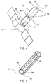
fig. 1 shows a perspective view of a space telescope comprised of two space vehicles which orbit in a formation, wherein the telescope comprises a shielding device according to a presently preferred embodiment of the present invention; -
fig. 2 shows a perspective view of one among two space vehicles offig. 1 , including the shielding device shown infig. 1 , in a first operating configuration, -
fig. 3 shows a perspective view of a space vehicle shown infig. 2 , wherein the shielding device is shown in a second operating configuration, -
fig. 4 shows a perspective view of space vehicle shown infig. 2 , wherein the shielding device is shown in a third operating configuration, -
fig. 5 shows a perspective view of a component of shielding device offig. 1 , wherein the structure of this component is schematically shown, -
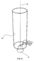
fig. 6 shows a perspective view, wherein a component of shielding device offig. 1 is shown in greater detail, this component being visible infig. 2 ; and -
fig. 7 shows a transversal section, wherein the telescope offig. 1 is schematically shown and operation of shielding device offig. 1 is schematically illustrated. - In the drawings, same or similar elements are indicated by same numeral references.
- With reference to
fig. 1 , 10 generally indicates a space telescope, in this example, a telescope for observing X-ray sources, including a pair of space vehicles, which may operate in a formation. More in particular, thepair 10 of space vehicles respectively comprises a Mirror Spacecraft 12 or MSC and a Detector Spacecraft 14 or DSC. The MSC carries on board focusing devices and observation optics, such as special mirrors or other types of optics, which are called "mirrors" in the following, and orients them towards the scientific objectives to be observed, such as a celestial body S1. The DSC carries on board anoptoelectronic apparatus 16 or detector (schematically shown infig. 6 ), on which images are focused, which may then be processed, stored and/or transmitted to earthbound stations. - More in particular, in the present example, the
detector 16 comprises a plurality of optoelectronic sensors (not shown in figures), which may cooperate with incident electromagnetic radiation X1, X2 (fig. 1 ), i.e. electromagnetic radiation which is generally within the nominal field of view ofdetector 16. The field of view of detector generally is the solid angle in the sky visible by detector. In the present example, without shielding devices, the nominal field of view is in particular of hemispherical shape, i.e. it is substantially equal to one half of the sky. - With reference to
fig. 1 , on board the DSC ashielding device 20 according to a currently preferred embodiment of the present invention is provided. Theshielding device 20 has to selectively shield the detector from incident electromagnetic radiation X1, X2, so thatdetector 16 is almost exclusively struck by incident electromagnetic radiation originating from the source, which is aimed at by the telescope, i.e. desired radiation X1. In this example, this desired radiation is coming fromMSC 12. In other words,shielding device 20 is capable of shielding thedetector 16 from incident electromagnetic radiation coming from sources, which are different with respect to the one, which is aimed at by the telescope, i.e. the undesired radiation X2. In this particular case, regarding an X-ray telescope, this undesired radiation comprises for example incident electromagnetic radiation coming from X-ray sources, such as celestial bodies S2, which are not the one at which the telescope is aiming. - With reference to
fig. 4 ,shielding device 20 comprises asupport structure 22, for supporting at least a shielding element orfilter - Advantageously,
support structure 22 is an extensible structure, and more in particular, an inflatable structure. Thestructure 22 is able to achieve a stand-by operating configuration (fig. 2 ), in which it is essentially folded together, and an active operating configuration (fig. 4 ), in which it is essentially completely unfolded. In other words, thestructure 22 is able to achieve a stand-by operating configuration, in which it is essentially deflated and compacted, and an active operating configuration, in which it is essentially completely inflated and extends along the longitudinal axis ZZ. Inflation of support structure is achieved, for example by means of a gas, by using a known pressurizing device. - From now on, when not otherwise stated, it is implied that the
support structure 20 is in the active operating condition. - According to an embodiment,
support structure 22 has a tubular shape, in this example a cylindrical shape, which extends around above said longitudinal extension axis ZZ. This axis, in the present example, is in particular coincident with focal axis ZZ oftelescope 10. - With reference to
fig. 5 , in which a particularly advantageous embodiment ofsupport structure 20 is schematically shown, this structure has a segmented structure, including a plurality ofinflatable chambers 28, which are positioned, according to a contiguous arrangement, about the focal axis ZZ. In the embodiment offig. 5 ,inflatable chambers 28 are longitudinally extensible chambers, which preferably extend along the whole length of support structure. Such segmented structure advantageously allows an increase of bending rigidity of inflatable structure. According to an alternate embodiment,structure 22 may however be provided in another way, for example in order to provide only one inflatable chamber. - Still referring to
fig. 4 ,shielding device 20 comprises a plurality offilters filters - According to an embodiment of the invention,
filters support structure 20 reaches the active operating configuration. In particular, in the appended figures,filters - In the example shown,
filters Filters - According to an embodiment, each filter body comprises a shielding portion, which in the example shown, is shaped like a
shielding annulus 30, and a pass-through portion, which, in the example shown, is a pass-through aperture 32, surrounded by the shielding annulus. In other words, in the present example, wherein the shielding portions are annuluses, pass-throughapertures 32 are circular apertures. - Pass-through
apertures 32 are each capable of letting incident electromagnetic radiation pass through, having incident angles within a respective first incident angle range.Shielding annuluses 30 may each shield the detector 16 (fig. 6 ) from incident electromagnetic radiation having incident angles within a respective second incident angle range, which is distinct from first range. More in particular, shielding annuluses may shield from incident electromagnetic radiation having incident angles greater than incident angles of electromagnetic radiation passing through respective pass-through apertures. - According to an embodiment, when the support structure is in the active operating configuration, the filters are aligned and mutually separated by predefined distances, along focal axis ZZ of telescope. In particular, in the embodiment shown in figures,
filters - According to a particularly advantageous embodiment, pass-through
apertures 32 have dimensions transversal to focal axis ZZ, which decrease when distance between filters anddetector 16 diminishes. When the size of pass-throughapertures 32 is reduced,respective shielding annuluses 30 may shield thedetector 16 from incident radiation forming incident angles, which increase with respect to focal axis. Preferably, also external diameter ofshielding annuluses 30 decreases with a reduction of distance between filters and detector. - According to a particularly advantageous embodiment, the supporting structure may be impregnated with a polymer resin, which may polymerize when exposed to solar radiation, in order to further stiffen the supporting structure. This allows an increase of rigidity of support structure, so that
filters DSC 14. - A further advantage obtained with polymer resin is that it preserves the rigidity of
support structure 22 even if theinflatable chambers 28 are damaged, for instance in case of loss of pressure due to perforation by small meteorites. - According to an advantageous embodiment, shielding
device 20 comprises a fixedbaffle 34, which is provided at or near the focal plane of detector (fig. 6 ). - Such a baffle is provided for shielding the detector from incident radiation having incident angles so high, that it cannot be shielded by shielding
annuluses 30. - According to an embodiment, the fixed
baffle 34 is a tubular rigid baffle, which extends around focal axis ZZ of telescope. Advantageously, therigid baffle 34 extends inside the support structure. In other words, in this example, wherein the support structure is of cylindrical tubular shape, the fixed baffle is completely housed within the cavity formed by internal walls of cylinder. In the embodiment shown in figures, the fixedbaffle 34 advantageously has dimensions, transversal to focal axis ZZ, which are less than those of pass-throughapertures 32 offilters support structure 22 goes from stand-by configuration to the active operating configuration, and vice versa. - An example of operation of shielding
device 20 is described in the following, according to an embodiment of the present invention. - Initially, and during the whole launch phase, the support structure is in the stand-by configuration. In particular, this structure is folded together with
filters fig. 2 ). Once the space telescope has reached its orbit, the support structure is inflated by the pressurizing device, in order to achieve its active operating configuration. - For a better understanding of operation of shielding
device 20, reference should be made tofig. 7 . In this figure, a geometric transversal section of shieldingdevice 20 is schematically shown, with the exception ofsupport structure 22, according to a currently preferred embodiment of present invention. In this figure, in particular,focal plane 36 ofdetector 16, fixedbaffle 34, and twofilters telescope 10, in this example approx. 20 (m), themirror 38, which is provided on board theMSC 12 and an additional shielding element orfilter 40, called "mirror skirt", are schematically shown. The mirror skirt is analogous tofilters mirror 38, in order to shield it from a first portion of incident electromagnetic radiation. -
Fig. 7 also shows a plurality of limit incident angles α, β, γ, δ, which are respectively defined between some reference directions P1, P2, P3, P4 and focal axis ZZ of detector. Above said reference directions are bound to geometry of shielding device and are particularly suitable for defining the shielding action offilters mirror skirt 40 and fixedbaffle 34. Limit angles α, β, γ, δ offig. 7 are respectively in an increasing order, and for sake of clarity, are illustrated by reference to an axis YY, which is parallel to focal axis ZZ. - Still with reference to
fig. 7 , it is to be noted thatmirror skirt 40 may shield from a first portion of undesired radiation, and more particularly, radiation having incident angles between angles α and β. In a similar manner,filter 24, including pass-through aperture having a major radius R1, and filter 26, including pass-through aperture having minor radius R2, are capable of shielding from undesired radiation having incident angles between angles β and γ and angles γ and δ, respectively. Finally, incident radiation having incident angles greater than angle δ is blocked by fixedbaffle 34. To summarize:mirror 40, filters 24, 26 and fixed baffle are capable of cooperating with incident electromagnetic radiation, so that the whole system substantially operates like a collimator, in order to allow only incident radiation with an incident angle less than angle α to reachfocal plane 36 ofdetector 16. - Based on above description, one may understand that a shielding device of above said type is able to fully achieve intended goals, overcoming the drawbacks of devices of the known art.
- The provision of a shielding device including plate-like filters and an inflatable support structure, provides a significant reduction of mass of shielding device with respect to solutions of known art, which use large monolithic cylinders.
- Furthermore, the provision of an inflatable support structure allows a considerable reduction of bulk of shielding structure, in particular during launch phase, so that this device is rendered essentially compatible with any launch device. This is particularly important in the case of X-ray space telescopes. These telescopes would in fact require monolithic cylinders, of such a size as to be rendered incompatible even with respect to commonly used launchers, used for putting into orbit space telescopes.
- According to a particularly advantageous embodiment, the shielding device according to the present invention is capable of shielding the detector also from optical radiation, such as solar radiation, reducing the need for, or even eliminating the need for particular optical filters, used in the known art for shielding detectors operating at X-ray wavelength, from solar radiation. This is particularly advantageous since in the case of low energy X-ray detectors, above said optical filters also attenuate the useful X radiation.
- It is clear that modifications and/or variations may be introduced in the examples described and illustrated above.
- According to an embodiment of the invention, both the support structure and the filters may be manufactured in alternate ways, with respect to above embodiments. For instance, the support structure may have a square sectional shape, whereas the filters may comprise square or generally polygonal shaped perforated plates. Filters may also be produced in order to provide pass-through portions, which are different from pass-through apertures. The pass-through portions may for example be made of materials substantially transparent with respect to desired electromagnetic radiation.
- According to an embodiment, the filters may be provided in such a way to allow a frequency filtering instead of a spatial filtering.
- In general, the number and size of filters may vary according to specific needs.
- Anyway, it is to be noted that, in general, a shielding device according to the present invention may be employed also for shielding optical and/or electronic devices, which differ from optics of a space telescopes, for instance those used for protecting telecommunication devices or other instruments provided on board of satellites, space stations or spacecrafts in general. In particular, the shielding device may be advantageously used with optical and/or electronic apparatuses, which operate in the frequency range of X-rays and/or γ -rays.
- The shielding device may be used for example also in fields, different from the specific space sector, for instance for aeronautical or terrestrial applications.
- It is useful to note that, in the end, in case of non-optical devices, the focal axis corresponds to another equivalent reference axis, which is characteristic for such devices. For example, for an antenna, the focal axis corresponds to the pointing axis of the antenna.
Claims (12)
- Shielding device (20) for optical and/or electronic apparatuses (16), which may cooperate with incident electromagnetic radiation (X1, X2), the shielding device including:- at least a filter (24, 26) provided for interacting with said incident electromagnetic radiation (X1, X2), for selectively filtering said radiation; and- a support structure (22) supporting the filter (24, 26);characterized in that:- said shielding device comprises at least two filters,- the support structure (22) is a tubular inflatable structure, which is able to achieve an operating stand-by configuration, in which it is substantially folded together, and an active operating configuration, in which it extends around a longitudinal extension axis (ZZ) and is essentially completely unfolded,- each filter (24, 26) is a rigid plate filter transversely positioned with respect to said longitudinal extension axis (ZZ) when the support structure reaches its active operating configuration, each rigid plate filter comprising a pass-through portion (32) and a shielding portion (30), said at least two filters being arranged in an aligned and mutually distanced way, according to predefined distances along said longitudinal extension axis (ZZ), when the support structure (22) reaches its active operating configuration.
- Shielding device (20) according to claim 1, wherein the incident electromagnetic radiation (X1, X2) comprises radiation having a frequency within the frequency range from X-rays to γ-rays.
- Shielding device (20) according to claim 1 or 2, wherein said longitudinal extension axis coincides with the focal axis (ZZ) or pointing axis of said optical and/or electronic apparatuses (16).
- Shielding device (20) according to any of preceding claims, wherein the incident electromagnetic radiation (X1, X2) may form incident angles with said longitudinal extension angle (ZZ), which are different from one another, the filter (24, 26) being such as to selectively filter incident electromagnetic radiation (X1, X2), according to respective incident angles.
- Shielding device (20) according to claim 1, wherein the pass-through portion is a pass-through aperture (32), and wherein the shielding portion (30) extends around said pass-through aperture.
- Shielding device (20) according to claim 5, wherein at least said pass-through portions (32) of filters have transversal dimensions (R1, R2), with respect to longitudinal extension axis (ZZ), which decrease with a decrease in distance between filters (24, 26) and optical and/or electronic apparatuses (16), the shielding portions (30) of filters being such as to shield the incident electromagnetic radiation (X1, X2) having incident angles increasing with a decrease in transversal dimensions (R1, R2) of pass-through portions.
- Shielding device (20) according to any of preceding claims, wherein the support structure (22) includes a plurality of inflatable chambers (28), which may achieve a longitudinal extension, and are arranged in a mutually contiguous manner around said longitudinal extension axis (ZZ).
- Shielding device (20) according to any of the preceding claims, wherein said support structure (22) comprises polymeric resins, which may polymerize when exposed to solar radiation, in order to stiffen the support structure.
- Shielding device (20) according to any of preceding claims, including a fixed baffle (34) provided at or near said optical and/or electronic apparatuses (16).
- Shielding device (20) according to claim 9, wherein the fixed baffle (34) is a tubular rigid baffle, which extends around said longitudinal extension axis, said fixed baffle extending inside the support structure (22) when said structure reaches the active operating configuration.
- Space vehicle (14) including a shielding device (20) according to any of preceding claims.
- Space vehicle (14) according to claim 11, wherein said vehicle is a satellite including a space telescope.
Priority Applications (3)
| Application Number | Priority Date | Filing Date | Title |
|---|---|---|---|
| EP08425546.2A EP2151704B1 (en) | 2008-08-07 | 2008-08-07 | Shielding device for optical and/or electronic apparatuses, and space vehicle comprising such device |
| ES08425546.2T ES2441070T3 (en) | 2008-08-07 | 2008-08-07 | Shielding device for optical and / or electronic devices, and space vehicle comprising said device |
| US12/512,177 US8083407B2 (en) | 2008-08-07 | 2009-07-30 | Shielding device for optical and/or electronic apparatuses, and space vehicle comprising such device |
Applications Claiming Priority (1)
| Application Number | Priority Date | Filing Date | Title |
|---|---|---|---|
| EP08425546.2A EP2151704B1 (en) | 2008-08-07 | 2008-08-07 | Shielding device for optical and/or electronic apparatuses, and space vehicle comprising such device |
Publications (2)
| Publication Number | Publication Date |
|---|---|
| EP2151704A1 EP2151704A1 (en) | 2010-02-10 |
| EP2151704B1 true EP2151704B1 (en) | 2013-11-20 |
Family
ID=40114430
Family Applications (1)
| Application Number | Title | Priority Date | Filing Date |
|---|---|---|---|
| EP08425546.2A Not-in-force EP2151704B1 (en) | 2008-08-07 | 2008-08-07 | Shielding device for optical and/or electronic apparatuses, and space vehicle comprising such device |
Country Status (3)
| Country | Link |
|---|---|
| US (1) | US8083407B2 (en) |
| EP (1) | EP2151704B1 (en) |
| ES (1) | ES2441070T3 (en) |
Families Citing this family (14)
| Publication number | Priority date | Publication date | Assignee | Title |
|---|---|---|---|---|
| KR101130119B1 (en) * | 2010-04-30 | 2012-03-28 | 한국과학기술원 | Optical Structure for Aerospace Engineering |
| ITTO20110323A1 (en) * | 2011-04-08 | 2012-10-09 | Thales Alenia Space Italia S P A C On Unico Socio | OPTICAL METROLOGICAL SYSTEM, LARGE AND PRECISION PROJECTIVE |
| FR2974348B1 (en) * | 2011-04-21 | 2014-01-24 | Thales Sa | DEVICE FOR PROTECTING AN OPTICAL INSTRUMENT OF A SATELLITE |
| FR2974787B1 (en) | 2011-05-05 | 2014-11-28 | Thales Sa | DEVICE FOR PROTECTING A MULTIFACEAL OPTICAL INSTRUMENT |
| CN102565987A (en) * | 2012-01-20 | 2012-07-11 | 中国科学院上海技术物理研究所 | Space large-caliber extensible shading cover structure |
| CN103832599A (en) * | 2012-11-27 | 2014-06-04 | 中国科学院空间科学与应用研究中心 | Composite shielding method for satellite to resist total dose effect |
| CN103336399A (en) * | 2013-07-10 | 2013-10-02 | 北京空间机电研究所 | Rotatable wedge-shaped sunshade capable of being unfolded segmentally |
| CN103693214B (en) * | 2013-12-06 | 2016-03-16 | 上海卫星工程研究所 | A kind ofly be applied to the large-scale of spacecraft and open up light shield mechanism |
| CN106324943B (en) * | 2016-10-20 | 2018-11-23 | 北京空间机电研究所 | A kind of space camera flexibility self-deploys hood |
| US10583939B2 (en) * | 2017-04-02 | 2020-03-10 | Richard Williams | Deployed electromagnetic radiation deflector shield (DERDS) which creates a zone of minimum radiation and magnetic/plasma effects for spacecraft and extra-planetary base station protection |
| FR3065203B1 (en) * | 2017-04-18 | 2019-06-21 | Arianegroup Sas | LIGHT TUBULAR STRUCTURE |
| CN108151783B (en) * | 2017-11-22 | 2019-10-15 | 中国科学院长春光学精密机械与物理研究所 | Optical remote sensor hood |
| US12253479B1 (en) * | 2021-12-08 | 2025-03-18 | Jaywant Philip Parmar | Space-based x-ray imaging system |
| WO2025253479A1 (en) * | 2024-06-04 | 2025-12-11 | Ntt株式会社 | Radiation shielding system, flying body, and radiation shielding method |
Citations (1)
| Publication number | Priority date | Publication date | Assignee | Title |
|---|---|---|---|---|
| DE2537436B1 (en) * | 1975-08-22 | 1977-01-27 | Christian Dipl-Ing Kopp | Underwater viewer with inflatable double walled case - which is collapsible for carriage, floatable, and resistant to mechanical shock |
Family Cites Families (13)
| Publication number | Priority date | Publication date | Assignee | Title |
|---|---|---|---|---|
| DE213315C (en) * | ||||
| US3518355A (en) * | 1968-12-06 | 1970-06-30 | Lectromagnetics Inc | Electromagnetic shield |
| US4370750A (en) * | 1981-05-15 | 1983-01-25 | The United States Of America As Represented By The Administrator Of The National Aeronautics And Space Administration | Extended range X-ray telescope |
| US4562583A (en) * | 1984-01-17 | 1985-12-31 | The United States Of America As Represented By The Administrator Of The National Aeronautics And Space Administration | Spectral slicing X-ray telescope with variable magnification |
| EP0201727A1 (en) * | 1985-05-15 | 1986-11-20 | Oerlikon-Contraves AG | Reflector aerial |
| CH666235A5 (en) * | 1987-06-24 | 1988-07-15 | Contraves Ag | INFLATABLE FOLDING STRUCTURE AND METHOD FOR PRODUCING FOLDING STRUCTURES. |
| US5345238A (en) * | 1990-03-13 | 1994-09-06 | Teledyne Industries, Inc. | Satellite signature suppression shield |
| US6118579A (en) * | 1998-04-04 | 2000-09-12 | Endemann; Thomas R. | Planetary astrographic telescope |
| US6024458A (en) * | 1998-10-16 | 2000-02-15 | Boeing North American | Optical shield with graduated conical baffles |
| US6481671B1 (en) * | 2000-08-14 | 2002-11-19 | Ball Aerospace & Technologies Corp. | Spacecraft sunshield for use in performing solar torque balancing |
| US7382332B2 (en) * | 2001-05-30 | 2008-06-03 | Essig Jr John Raymond | Modular inflatable multifunction field-deployable apparatus and methods of manufacture |
| US7144123B2 (en) * | 2003-04-09 | 2006-12-05 | Lundgren Mark A | Space optics cover and extendable baffle for contamination control |
| FR2867283B1 (en) * | 2004-03-05 | 2006-05-19 | Centre Nat Etd Spatiales | STELLAR OCCULTATION METHOD, DEVICE AND SET FOR IMPLEMENTING THE METHOD |
-
2008
- 2008-08-07 EP EP08425546.2A patent/EP2151704B1/en not_active Not-in-force
- 2008-08-07 ES ES08425546.2T patent/ES2441070T3/en active Active
-
2009
- 2009-07-30 US US12/512,177 patent/US8083407B2/en not_active Expired - Fee Related
Patent Citations (1)
| Publication number | Priority date | Publication date | Assignee | Title |
|---|---|---|---|---|
| DE2537436B1 (en) * | 1975-08-22 | 1977-01-27 | Christian Dipl-Ing Kopp | Underwater viewer with inflatable double walled case - which is collapsible for carriage, floatable, and resistant to mechanical shock |
Also Published As
| Publication number | Publication date |
|---|---|
| US8083407B2 (en) | 2011-12-27 |
| US20100034358A1 (en) | 2010-02-11 |
| EP2151704A1 (en) | 2010-02-10 |
| ES2441070T3 (en) | 2014-01-31 |
Similar Documents
| Publication | Publication Date | Title |
|---|---|---|
| US8083407B2 (en) | Shielding device for optical and/or electronic apparatuses, and space vehicle comprising such device | |
| EP3600841B1 (en) | Additive manufacturing system for on-orbit fabrication of structures | |
| Weisskopf et al. | An overview of the performance and scientific results from the Chandra X‐Ray Observatory | |
| Culhane et al. | The EUV imaging spectrometer for Hinode | |
| EP0888967B1 (en) | Spacecraft platforms | |
| US10442557B2 (en) | Satellite comprising an optical photography instrument | |
| US11506865B2 (en) | Honeycomb sandwich panel, optical device, and artificial satellite | |
| Weisskopf et al. | Advanced X-ray Astrophysics Facility (AXAF): an overview | |
| US8139932B2 (en) | Imaging system and method | |
| Schwartz | Invited review article: the Chandra X-ray observatory | |
| Ramsey et al. | The imaging x-ray polarimetry explorer (IXPE): technical overview IV | |
| Martin et al. | Next-generation active telescope for space astronomy | |
| Bui et al. | System design and development of VELOX-I nanosatellite | |
| Ayre et al. | ATHENA: system design and implementation for a next generation x-ray telescope | |
| Robinson et al. | Mechanical overview of the International X-ray Observatory | |
| Lichodziejewski et al. | Inflatably deployed membrane waveguide array antenna for space | |
| Martin et al. | ATSA: a cold, active telescope for Space Astronomy | |
| Fiore et al. | HEXIT-SAT: a mission concept for X-ray grazing incidence telescopes from 0.5 to 70 keV | |
| Lillie et al. | Key enabling technologies for the next generation of space telescopes | |
| Bely | The NGST'yardstick mission' | |
| Deininger et al. | The small satellite-based, imaging x-ray polarimeter explorer (IXPE) mission | |
| Rather et al. | Breakthrough technologies for ultra large telescopes | |
| Mathew et al. | All spherical optical design of an Ultraviolet Cosmic Imager | |
| Cotton et al. | Wide-angle geocoronal telescope (WIDGET) | |
| Ogasaka et al. | Development of supermirror hard X-ray telescope and the results of the first InFOCuS flight observation |
Legal Events
| Date | Code | Title | Description |
|---|---|---|---|
| PUAI | Public reference made under article 153(3) epc to a published international application that has entered the european phase |
Free format text: ORIGINAL CODE: 0009012 |
|
| AK | Designated contracting states |
Kind code of ref document: A1 Designated state(s): AT BE BG CH CY CZ DE DK EE ES FI FR GB GR HR HU IE IS IT LI LT LU LV MC MT NL NO PL PT RO SE SI SK TR |
|
| AX | Request for extension of the european patent |
Extension state: AL BA MK RS |
|
| 17P | Request for examination filed |
Effective date: 20100805 |
|
| AKX | Designation fees paid |
Designated state(s): DE ES FR GB IT NL |
|
| 17Q | First examination report despatched |
Effective date: 20110927 |
|
| GRAP | Despatch of communication of intention to grant a patent |
Free format text: ORIGINAL CODE: EPIDOSNIGR1 |
|
| INTG | Intention to grant announced |
Effective date: 20130626 |
|
| GRAS | Grant fee paid |
Free format text: ORIGINAL CODE: EPIDOSNIGR3 |
|
| GRAA | (expected) grant |
Free format text: ORIGINAL CODE: 0009210 |
|
| AK | Designated contracting states |
Kind code of ref document: B1 Designated state(s): DE ES FR GB IT NL |
|
| REG | Reference to a national code |
Ref country code: GB Ref legal event code: FG4D |
|
| REG | Reference to a national code |
Ref country code: DE Ref legal event code: R096 Ref document number: 602008028816 Country of ref document: DE Effective date: 20140116 |
|
| REG | Reference to a national code |
Ref country code: ES Ref legal event code: FG2A Ref document number: 2441070 Country of ref document: ES Kind code of ref document: T3 Effective date: 20140131 |
|
| REG | Reference to a national code |
Ref country code: NL Ref legal event code: T3 |
|
| REG | Reference to a national code |
Ref country code: DE Ref legal event code: R097 Ref document number: 602008028816 Country of ref document: DE |
|
| PLBE | No opposition filed within time limit |
Free format text: ORIGINAL CODE: 0009261 |
|
| STAA | Information on the status of an ep patent application or granted ep patent |
Free format text: STATUS: NO OPPOSITION FILED WITHIN TIME LIMIT |
|
| 26N | No opposition filed |
Effective date: 20140821 |
|
| REG | Reference to a national code |
Ref country code: DE Ref legal event code: R097 Ref document number: 602008028816 Country of ref document: DE Effective date: 20140821 |
|
| REG | Reference to a national code |
Ref country code: FR Ref legal event code: PLFP Year of fee payment: 9 |
|
| REG | Reference to a national code |
Ref country code: FR Ref legal event code: PLFP Year of fee payment: 10 |
|
| REG | Reference to a national code |
Ref country code: FR Ref legal event code: PLFP Year of fee payment: 11 |
|
| PGFP | Annual fee paid to national office [announced via postgrant information from national office to epo] |
Ref country code: NL Payment date: 20200814 Year of fee payment: 13 |
|
| PGFP | Annual fee paid to national office [announced via postgrant information from national office to epo] |
Ref country code: FR Payment date: 20200724 Year of fee payment: 13 Ref country code: GB Payment date: 20200728 Year of fee payment: 13 Ref country code: DE Payment date: 20200729 Year of fee payment: 13 |
|
| PGFP | Annual fee paid to national office [announced via postgrant information from national office to epo] |
Ref country code: IT Payment date: 20200728 Year of fee payment: 13 |
|
| REG | Reference to a national code |
Ref country code: ES Ref legal event code: FD2A Effective date: 20210105 |
|
| PG25 | Lapsed in a contracting state [announced via postgrant information from national office to epo] |
Ref country code: ES Free format text: LAPSE BECAUSE OF NON-PAYMENT OF DUE FEES Effective date: 20190808 |
|
| REG | Reference to a national code |
Ref country code: DE Ref legal event code: R119 Ref document number: 602008028816 Country of ref document: DE |
|
| REG | Reference to a national code |
Ref country code: NL Ref legal event code: MM Effective date: 20210901 |
|
| GBPC | Gb: european patent ceased through non-payment of renewal fee |
Effective date: 20210807 |
|
| PG25 | Lapsed in a contracting state [announced via postgrant information from national office to epo] |
Ref country code: NL Free format text: LAPSE BECAUSE OF NON-PAYMENT OF DUE FEES Effective date: 20210901 |
|
| PG25 | Lapsed in a contracting state [announced via postgrant information from national office to epo] |
Ref country code: IT Free format text: LAPSE BECAUSE OF NON-PAYMENT OF DUE FEES Effective date: 20210807 Ref country code: GB Free format text: LAPSE BECAUSE OF NON-PAYMENT OF DUE FEES Effective date: 20210807 Ref country code: FR Free format text: LAPSE BECAUSE OF NON-PAYMENT OF DUE FEES Effective date: 20210831 Ref country code: DE Free format text: LAPSE BECAUSE OF NON-PAYMENT OF DUE FEES Effective date: 20220301 |