EP2151416A1 - Apparatus for producing trichlorosilane and method for producing trichlorosilane - Google Patents
Apparatus for producing trichlorosilane and method for producing trichlorosilane Download PDFInfo
- Publication number
- EP2151416A1 EP2151416A1 EP09167090A EP09167090A EP2151416A1 EP 2151416 A1 EP2151416 A1 EP 2151416A1 EP 09167090 A EP09167090 A EP 09167090A EP 09167090 A EP09167090 A EP 09167090A EP 2151416 A1 EP2151416 A1 EP 2151416A1
- Authority
- EP
- European Patent Office
- Prior art keywords
- raw material
- decomposing furnace
- producing
- material supplying
- tube
- Prior art date
- Legal status (The legal status is an assumption and is not a legal conclusion. Google has not performed a legal analysis and makes no representation as to the accuracy of the status listed.)
- Granted
Links
Images





Classifications
-
- C—CHEMISTRY; METALLURGY
- C01—INORGANIC CHEMISTRY
- C01B—NON-METALLIC ELEMENTS; COMPOUNDS THEREOF; METALLOIDS OR COMPOUNDS THEREOF NOT COVERED BY SUBCLASS C01C
- C01B33/00—Silicon; Compounds thereof
- C01B33/08—Compounds containing halogen
- C01B33/107—Halogenated silanes
-
- B—PERFORMING OPERATIONS; TRANSPORTING
- B01—PHYSICAL OR CHEMICAL PROCESSES OR APPARATUS IN GENERAL
- B01J—CHEMICAL OR PHYSICAL PROCESSES, e.g. CATALYSIS OR COLLOID CHEMISTRY; THEIR RELEVANT APPARATUS
- B01J19/00—Chemical, physical or physico-chemical processes in general; Their relevant apparatus
- B01J19/0053—Details of the reactor
- B01J19/006—Baffles
-
- B—PERFORMING OPERATIONS; TRANSPORTING
- B01—PHYSICAL OR CHEMICAL PROCESSES OR APPARATUS IN GENERAL
- B01J—CHEMICAL OR PHYSICAL PROCESSES, e.g. CATALYSIS OR COLLOID CHEMISTRY; THEIR RELEVANT APPARATUS
- B01J19/00—Chemical, physical or physico-chemical processes in general; Their relevant apparatus
- B01J19/18—Stationary reactors having moving elements inside
- B01J19/1812—Tubular reactors
-
- B—PERFORMING OPERATIONS; TRANSPORTING
- B01—PHYSICAL OR CHEMICAL PROCESSES OR APPARATUS IN GENERAL
- B01J—CHEMICAL OR PHYSICAL PROCESSES, e.g. CATALYSIS OR COLLOID CHEMISTRY; THEIR RELEVANT APPARATUS
- B01J19/00—Chemical, physical or physico-chemical processes in general; Their relevant apparatus
- B01J19/18—Stationary reactors having moving elements inside
- B01J19/1812—Tubular reactors
- B01J19/1843—Concentric tube
-
- B—PERFORMING OPERATIONS; TRANSPORTING
- B01—PHYSICAL OR CHEMICAL PROCESSES OR APPARATUS IN GENERAL
- B01J—CHEMICAL OR PHYSICAL PROCESSES, e.g. CATALYSIS OR COLLOID CHEMISTRY; THEIR RELEVANT APPARATUS
- B01J19/00—Chemical, physical or physico-chemical processes in general; Their relevant apparatus
- B01J19/24—Stationary reactors without moving elements inside
- B01J19/2415—Tubular reactors
-
- B—PERFORMING OPERATIONS; TRANSPORTING
- B01—PHYSICAL OR CHEMICAL PROCESSES OR APPARATUS IN GENERAL
- B01J—CHEMICAL OR PHYSICAL PROCESSES, e.g. CATALYSIS OR COLLOID CHEMISTRY; THEIR RELEVANT APPARATUS
- B01J19/00—Chemical, physical or physico-chemical processes in general; Their relevant apparatus
- B01J19/24—Stationary reactors without moving elements inside
- B01J19/2415—Tubular reactors
- B01J19/244—Concentric tubes
-
- B—PERFORMING OPERATIONS; TRANSPORTING
- B01—PHYSICAL OR CHEMICAL PROCESSES OR APPARATUS IN GENERAL
- B01J—CHEMICAL OR PHYSICAL PROCESSES, e.g. CATALYSIS OR COLLOID CHEMISTRY; THEIR RELEVANT APPARATUS
- B01J2219/00—Chemical, physical or physico-chemical processes in general; Their relevant apparatus
- B01J2219/00049—Controlling or regulating processes
- B01J2219/00051—Controlling the temperature
- B01J2219/00074—Controlling the temperature by indirect heating or cooling employing heat exchange fluids
- B01J2219/00087—Controlling the temperature by indirect heating or cooling employing heat exchange fluids with heat exchange elements outside the reactor
-
- B—PERFORMING OPERATIONS; TRANSPORTING
- B01—PHYSICAL OR CHEMICAL PROCESSES OR APPARATUS IN GENERAL
- B01J—CHEMICAL OR PHYSICAL PROCESSES, e.g. CATALYSIS OR COLLOID CHEMISTRY; THEIR RELEVANT APPARATUS
- B01J2219/00—Chemical, physical or physico-chemical processes in general; Their relevant apparatus
- B01J2219/00049—Controlling or regulating processes
- B01J2219/00051—Controlling the temperature
- B01J2219/00159—Controlling the temperature controlling multiple zones along the direction of flow, e.g. pre-heating and after-cooling
-
- B—PERFORMING OPERATIONS; TRANSPORTING
- B01—PHYSICAL OR CHEMICAL PROCESSES OR APPARATUS IN GENERAL
- B01J—CHEMICAL OR PHYSICAL PROCESSES, e.g. CATALYSIS OR COLLOID CHEMISTRY; THEIR RELEVANT APPARATUS
- B01J2219/00—Chemical, physical or physico-chemical processes in general; Their relevant apparatus
- B01J2219/00761—Details of the reactor
- B01J2219/00763—Baffles
- B01J2219/00765—Baffles attached to the reactor wall
-
- B—PERFORMING OPERATIONS; TRANSPORTING
- B01—PHYSICAL OR CHEMICAL PROCESSES OR APPARATUS IN GENERAL
- B01J—CHEMICAL OR PHYSICAL PROCESSES, e.g. CATALYSIS OR COLLOID CHEMISTRY; THEIR RELEVANT APPARATUS
- B01J2219/00—Chemical, physical or physico-chemical processes in general; Their relevant apparatus
- B01J2219/00761—Details of the reactor
- B01J2219/00763—Baffles
- B01J2219/00779—Baffles attached to the stirring means
-
- Y—GENERAL TAGGING OF NEW TECHNOLOGICAL DEVELOPMENTS; GENERAL TAGGING OF CROSS-SECTIONAL TECHNOLOGIES SPANNING OVER SEVERAL SECTIONS OF THE IPC; TECHNICAL SUBJECTS COVERED BY FORMER USPC CROSS-REFERENCE ART COLLECTIONS [XRACs] AND DIGESTS
- Y02—TECHNOLOGIES OR APPLICATIONS FOR MITIGATION OR ADAPTATION AGAINST CLIMATE CHANGE
- Y02E—REDUCTION OF GREENHOUSE GAS [GHG] EMISSIONS, RELATED TO ENERGY GENERATION, TRANSMISSION OR DISTRIBUTION
- Y02E60/00—Enabling technologies; Technologies with a potential or indirect contribution to GHG emissions mitigation
- Y02E60/30—Hydrogen technology
- Y02E60/32—Hydrogen storage
Definitions
- the gas discharge tube may be formed in a double-tube structure to surround the periphery of the upper part of the raw material supplying tube on the outside of the decomposing furnace.
- Gas discharged from the decomposing furnace after the reaction is at a high temperature.
- the discharge tube of the high-temperature gas surrounds the raw material supplying tube, heat exchange is made between the polymer and the hydrogen chloride flowing through the raw material supplying tube and the gas flowing through the discharge tube. Therefore, the polymer or the like can be preheated before being introduced into the decomposing furnace, so that it is possible to enhance efficiency of the reaction between the polymer and the hydrogen chloride.
- the decomposing furnace may be provided with a pressurized gas injection tube for injecting pressurized gas into the decomposing furnace and a furnace fluid discharge tube for discharging fluids in the furnace expelled by the pressurized gas.
- a pressurized gas injection tube for injecting pressurized gas into the decomposing furnace
- a furnace fluid discharge tube for discharging fluids in the furnace expelled by the pressurized gas.
- a number of spherical rolling members provided on the inner bottom portion of the decomposing furnace may further be included. Since silicon oxide is more likely to be deposited on the inner bottom portion of the decomposing furnace, by inserting from the outside a bar-shaped member or the like to move the rolling members, the silicon oxide can be crushed, so that the removal operation thereof can be easily performed.
- the pressurized gas injection tube 23 is provided with valves 25 and 26 for switching between the passageways of the raw material supplying tube 3 and the reaction chamber 13.
- the furnace fluid discharge tube 24 is used for discharging fluids in the furnace which contain silicon oxide and are removed by the injection of pressurized gas from the raw material supplying tube 3 or the reaction chamber 13.
- the furnace fluid discharge tube 24 is provided with valves 27 and 28 for switching the passageways of the raw material supplying tube 3 or the reaction chamber 13.
- the furnace fluid discharge tube 24 is connected to a cyclone 29. Silicon oxide collected in the cyclone 29 is processed by a silicon oxide processing system 30.
- the valves 25 to 28 of the pressurized gas injection tube 23 and the furnace fluid discharge tube 24 are closed during the operation of the decomposing furnace 2 and opened during maintenance, as described later, to clean the inside of the decomposing furnace 2.
- the communicating port 22 is provided separately from the gas discharge tube 4 illustrated in FIG. 1 , however, the gas discharge tube 4 may also be used as the communicating port 22.
- a fluidizing chlorination furnace 31 for producing crude TCS by reacting metallurgical silicon (Me-Si) and hydrogen chloride (HCl) with each other a distillation column 32 for distilling of the produced gas containing the crude TCS which is produced in the fluidizing chlorination furnace 31, an evaporator 33 for evaporating the purified T
- the heat from the heating unit 8 on the outer side of the furnace main body 5 is transferred through the reaction chamber 13 and the fin 14 around the raw material supplying tube 3, and the internal fluid mixture is preheated by the heat. Accordingly, most of the fluid mixture is evaporated and gasified, and the fluid mixture is introduced into the reaction chamber 13 through the lower end opening 3 a of the raw material supplying tube 3.
- FIG. 5 illustrates an apparatus for producing TCS according to a second embodiment of the present invention.
- the two gas discharge tubes 4 are connected to the end plate 7 of the decomposing furnace 2.
- a gas discharge tube 42 is formed as a cylinder which a diameter of the cylinder is larger than the raw material supplying tube 3 to surround the section of the raw material supplying tube 3 which protrudes upward from the decomposing furnace 2 such that the raw material supplying tube 3 and the gas discharge tube 42 are provided in a double-tube structure.
- FIG 6 illustrates an apparatus for producing TCS according to a third embodiment of the present invention.
- the apparatus for producing trichlorosilane 51 is provided with an agitating member 54 formed by fixing a second fin 53 to the periphery of a core bar 52 in the raw material supplying tube 3.
- the raw material supplying tube 3 is provided with the same preheating unit 43 as in the second embodiment, the agitating member 54 has a length extending downward from the preheating unit 43 to the vicinity of the inner bottom portion of the furnace main body 5, and the front end portion thereof protrudes from the lower end opening 3a of the raw material supplying tube 3.
- the agitating member 54 may also be provided only in the preheating unit 43.
- the fin 61 having the static mixer structure Due to the fin 61 having the static mixer structure, fluid is agitated and mixed in combination of a dividing operation of dividing the fluid into two flows whenever the fluid passes through the single element 62, a mixing (or converting) operation of moving the fluid from the center to the outside or from the outside to the center along the twisted surface of the element 62, and a reversing operation of reversing the rotation direction at every element 62 for agitating.
- a dividing operation of dividing the fluid into two flows whenever the fluid passes through the single element 62 a mixing (or converting) operation of moving the fluid from the center to the outside or from the outside to the center along the twisted surface of the element 62, and a reversing operation of reversing the rotation direction at every element 62 for agitating.
- a mixing (or converting) operation of moving the fluid from the center to the outside or from the outside to the center along the twisted surface of the element 62
- a reversing operation of
- the fin is fixed to the outer peripheral surface of the raw material supplying tube.
- the fin may be fixed to the inner peripheral surface of the furnace main body with a gap from the raw material supplying tube.
- a hole may be provided along the injection direction to the fin 14 existing in the injection direction.
- a fin for heat transfer may be provided to the outside of the section of the raw material supplying tube 3 corresponding to the preheating unit 43.
Landscapes
- Chemical & Material Sciences (AREA)
- Organic Chemistry (AREA)
- Chemical Kinetics & Catalysis (AREA)
- Inorganic Chemistry (AREA)
- Silicon Compounds (AREA)
Abstract
Description
- The present invention relates to a producing apparatus for decomposing and converting high boiling point chlorosilanes-containing materials (hereinafter, referred to as polymer) generated in a polycrystalline silicon producing process and in a trichlorosilane producing or converting process into trichlorosilane, and more particularly, to an apparatus for producing trichlorosilane by decomposing a polymer produced in a chlorination process, a polymer separated from an exhaust gas of a reaction process of polycrystalline silicon, or a polymer produced in a conversion process for producing trichlorosilane from silicon tetrachloride in an exhaust gas, and a method for producing trichlorosilane.
Priority is claimed on Japanese Patent Application No.2008-201863, filed on August 5, 2008 - High-purity polycrystalline silicon used for semiconductor materials are mainly produced by the Siemens process using trichlorosilane (SiHCl3: TCS) and hydrogen as the raw materials. The Siemens process is a process of introducing a gas mixture of trichlorosilane and hydrogen into a reactor so as to come in contact with a glowing silicon rod, and depositing silicon on the surface of the silicon rod due to the hydrogen reduction and thermal decomposition of trichlorosilane at high temperature. For the high-purity trichlorosilane introduced into the reactor, for example, high-purity trichlorosilane obtained by distilling and purifying crude trichlorosilane obtained through a chlorination process is used. The chlorination process is a process for introducing metallurgical silicon and hydrogen chloride into a fluidizing chlorination furnace so as to react with each other and produce crude trichlorosilane using the chlorination of silicon.
- In the producing of polycrystalline silicon, gases discharged from the reactor include unreacted trichlorosilane, hydrogen chloride, silicon tetrachloride (STC) as a byproduct, and chlorosilanes (referred to as high boiling point chlorosilanes) having higher boiling points than silicon tetrachlorides such as tetrachlorodisilane (Si2H2Cl4) and hexachlorodisilane (Si2Cl6) (refer to
WO02/012122 - Conventionally, polymers are produced when the gas produced in the chlorination furnace or in the converter, or the gas discharged from the reactor, is collected and distilled. These polymers should be hydrolyzed and disposed of. Accordingly, there is a problem in that costs involved in the hydrolysis and waste disposal are expensive.
- In addition, a method is known for returning polymers generated in the producing of polycrystalline silicon to a fluid reaction container to be separated and using the separated polymers to produce trichlorosilane (refer to
JP-A-01-188414 - The present invention is designed to solve the above-mentioned problems. An object of the present invention is to provide a producing apparatus for decomposing and converting polymers separated in a polycrystalline silicon producing process, and in a trichlorosilane producing or converting process, into trichlorosilane.
- According to an aspect of the present invention, there is provided an apparatus for producing trichlorosilane which introduces, into a decomposing furnace, hydrogen chloride and polymer containing high boiling point chlorosilanes generated in a polycrystalline silicon producing process, in a trichlorosilane producing or in a converting process, and reacting them with each other at high temperatures such that the polymer decomposes, thereby producing trichlorosilane. The apparatus for producing trichlorosilane includes: in the decomposing furnace, a heating unit heating the inside of the decomposing furnace, a raw material supplying tube for guiding the polymer and the hydrogen chloride to the inner bottom portion of the decomposing furnace along the longitudinal direction of the decomposing furnace and supplying to the decomposing furnace through its lower end opening, a reaction chamber provided between the outer peripheral surface of the raw material supplying tube and the inner peripheral surface of the decomposing furnace, and a gas discharge tube for discharging reaction gas from the top of the reaction chamber. In addition, a fin is formed integrally with at least one of the outer peripheral surface of the raw material supplying tube or the inner peripheral surface of the decomposing furnace. The fin guides the fluid mixture including the polymer and the hydrogen chloride supplied from the lower end opening of the raw material supplying tube to be agitated and rise upward in the reaction chamber.
- In the apparatus for producing trichlorosilane, since trichlorosilane is produced by decomposing polymer, trichlorosilane can be recovered by decomposing polymer separated in, for example, the polycrystalline silicon producing process. Therefore, in the apparatus for producing trichlorosilane, the burden due to the waste disposal of the polymer using hydrolysis can be significantly reduced. In addition, since the recovered trichlorosilane is reused, the use efficiency of the raw material is increased, so that it is possible to reduce the producing cost of polycrystalline silicon. In addition, since polymer and hydrogen chloride are agitated and rise upward to the top of the decomposing furnace while coming in contact with the fin in the reaction chamber on the outside of the raw material supplying tube, heat is also transferred from the fin for effective heating, and the temperature in the furnace can be uniformized, thereby achieving a highly efficient reaction. In addition, although silicon oxide is generated by a reaction between oxides contained in the polymer and moisture in the hydrogen chloride gas, as the reaction chamber is provided on the outside of the raw material supplying tube, it is possible to suppress the clogging up of the raw material supplying tube with the silicon oxide.
- In the apparatus for producing trichlorosilane according to the aspect of the present invention, the raw material supplying tube may be provided along the center axis of the decomposing furnace in a straight manner.
With such a configuration, since the raw material supplying tube is provided in the straight manner, although silicon oxide adheres to the inner surface of the lower end opening of the raw material supplying tube, it is possible to easily perform a removal operation of the silicon oxide by inserting a bar-shaped member into the raw material supplying tube, or the like. - In the apparatus for producing trichlorosilane according to the aspect of the present invention, a polymer supplying system and a hydrogen chloride supplying system may be connected to an upper section of the raw material supplying tube which protrudes outward from the decomposing furnace, and an agitating member having a second fin may be inserted into the raw material supplying tube.
With such a configuration, the polymer and the hydrogen chloride can be mixed by the second fin in the raw material supplying tube before they are supplied to the reaction chamber, so that the reaction in the reaction chamber effectively occurs. In this case, when the agitating member moves vertically, although silicon oxide is adhered to the lower end opening of the raw material supplying tube and the inner bottom portion of the decomposing furnace, the silicon oxide can be crushed by moving the agitating member vertically, so that the silicon oxide can be easily removed. - In the apparatus for producing trichlorosilane according to the aspect of the present invention, the gas discharge tube may be formed in a double-tube structure to surround the periphery of the upper part of the raw material supplying tube on the outside of the decomposing furnace.
Gas discharged from the decomposing furnace after the reaction is at a high temperature. In the configuration in which the discharge tube of the high-temperature gas surrounds the raw material supplying tube, heat exchange is made between the polymer and the hydrogen chloride flowing through the raw material supplying tube and the gas flowing through the discharge tube. Therefore, the polymer or the like can be preheated before being introduced into the decomposing furnace, so that it is possible to enhance efficiency of the reaction between the polymer and the hydrogen chloride. - In the apparatus for producing trichlorosilane according to the aspect of the present invention, the decomposing furnace may be provided with a pressurized gas injection tube for injecting pressurized gas into the decomposing furnace and a furnace fluid discharge tube for discharging fluids in the furnace expelled by the pressurized gas.
With such a configuration, although silicon oxide generated by a reaction between oxides contained in the polymer and moisture in the hydrogen chloride gas is adhered to the decomposing furnace, the adhered silicon oxide can be removed by the pressurize gas by injecting the pressurized gas continuously or intermittently to clean the inside. As the pressurized gas, an inert gas, such as nitrogen or the like, may be used. - In the apparatus for producing trichlorosilane according to the aspect of the present invention, a number of spherical rolling members provided on the inner bottom portion of the decomposing furnace may further be included.
Since silicon oxide is more likely to be deposited on the inner bottom portion of the decomposing furnace, by inserting from the outside a bar-shaped member or the like to move the rolling members, the silicon oxide can be crushed, so that the removal operation thereof can be easily performed. - According to another aspect of the present invention, there is provided a method for producing trichlorosilane which introduces into a decomposing furnace hydrogen chloride and polymer containing high boiling point chlorosilanes generated in a polycrystalline silicon producing process or in a trichlorosilane producing process or in a trichlorosilane converting process, and reacting them with each other at high temperature such that the polymer decomposes, thereby producing trichlorosilane. The decomposing furnace is preheated, and the polymer and the hydrogen chloride are supplied from the top of the heated decomposing furnace and guided to the inner bottom portion of the decomposing furnace while being gasified due to the preheated the decomposing furnace. Thereafter, a fluid mixture of the polymer and the hydrogen chloride is agitated and reacts with each other while rising upward from the inner bottom portion in the decomposing furnace.
- According to the aspects of the present invention, since trichlorosilane is produced by decomposing polymer, trichlorosilane can be recovered by decomposing polymer separated in, for example, the polycrystalline silicon producing process or the trichlorosilane producing process. Therefore, the burden of waste disposal of the polymer using hydrolysis can be significantly reduced. In addition, since the recovered trichlorosilane is reused, the use efficiency of the raw material is increased, so that it is possible to reduce the producing cost of polycrystalline silicon. In addition, since the polymer and the hydrogen chloride are agitated and rise upward to the top of the decomposing furnace while coming in contact with the fin in the reaction chamber on the outside of the raw material supplying tube, heat is also transferred from the fin for effective heating, and the temperature in the furnace can be uniformized, thereby achieving a highly efficient reaction. In addition, although silicon oxide is generated by the reaction, since the reaction chamber is provided on the outside of the raw material supplying tube, it is possible to suppress the clogging up of the raw material supplying tube by the silicon oxide.
-
-
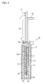
FIG 1 is a longitudinal sectional view showing an apparatus for producing trichlorosilane according to a first embodiment of the present invention. -
FIG. 2 is a longitudinal sectional view showing the apparatus for producing trichlorosilane ofFIG. 1 when viewed from side. -
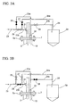
FIG. 3A is a plumbing diagram showing an example of discharging silicon oxide in a decomposing furnace by using the pressurized gas injection tube illustrated inFIG. 2 . -
FIG. 3B is a plumbing diagram showing an example of discharging silicon oxide in a decomposing furnace by using the pressurized gas injection tube illustrated inFIG. 2 . -
FIG. 4 is a flow diagram showing an example of a polycrystalline silicon producing process using an apparatus for producing trichlorosilane of the present invention. -
FIG. 5 is a longitudinal sectional view showing an apparatus for producing trichlorosilane according to a second embodiment of the present invention. -
FIG. 6 is a longitudinal sectional view showing an apparatus for producing trichlorosilane according to a third embodiment of the present invention. -
FIG. 7 is a front view showing a raw material supplying tube having a modified example of a fin used for the apparatus for producing trichlorosilane of the present invention. -
FIG 8 is a bottom view ofFIG. 7 . -
FIG. 9 is a longitudinal sectional view of the main part showing an example of providing a rolling member in a decomposing furnace of the apparatus for producing trichlorosilane according to the third embodiment ofFIG 6 . - Hereinafter, exemplary embodiments of an apparatus for producing trichlorosilane (SiHCl3: TCS)of the present invention will be described with reference to the accompanying drawings.
FIGS. 1 to 3B illustrate an apparatus for producing TCS according to a first embodiment. The apparatus for producingtrichlorosilane 1 includes a cylindrical decomposingfurnace 2 provided along in a longitudinal direction of the decomposing furnace, a rawmaterial supplying tube 3 which is inserted from above on the decomposingfurnace 2 to the inner bottom portion along the center axis C of the decomposingfurnace 2, and agas discharge tube 4 for discharging reaction gas from the top portion of the decomposingfurnace 2.
The decomposingfurnace 2 includes a furnacemain body 5 which is bottomed-cylindrical and has atop flange 5a, anend plate 7 which is joined to thetop flange 5a of the furnacemain body 5 withbolts 6 which can be detached, and aheating unit 8 heating the inside of the furnacemain body 5 from the periphery thereof. In addition, aninner bottom surface 5b of the furnacemain body 5 is formed as a spherical concave surface.
Theheating unit 8 includes a body-section heater 8a for surrounding the outer peripheral surface of the furnacemain body 5 and the bottom-section heater 8b for covering the outer bottom surface of the furnacemain body 5. InFIGS. 1 and2 ,reference numeral 9 denotes a frame for covering theheating unit 8. - The raw
material supplying tube 3 is formed as a straight cylinder, and penetrates through and is fixed vertically to theend plate 7 of the decomposingfurnace 2 and protrudes from the top of the decomposingfurnace 2. Apolymer supplying system 11 and a hydrogenchloride supplying system 12 are connected to a base end portion (upper end portion). In addition, the insertion length of the rawmaterial supplying tube 3 from theend plate 7 through the furnacemain body 5 is slightly shorter than the depth of the furnacemain body 5, so that alower end opening 3a is slightly spaced from theinner bottom surface 5b of the furnacemain body 5 when theend plate 7 is fixed to thetop flange 5a of the furnacemain body 5. - In addition, a cylindrical space formed between the outer peripheral surface of the raw
material supplying tube 3, which is inserted into the decomposingfurnace 2, and the inner peripheral surface of the furnacemain body 5 of the decomposingfurnace 2 is areaction chamber 13. Afin 14 is fixed to the outer peripheral surface of the rawmaterial supplying tube 3 exposed to thereaction chamber 13. Thefin 14 is, for example, arranged as a spiral shape along the longitudinal direction of the rawmaterial supplying tube 3. The outer peripheral end of thefin 14 is close to the inner peripheral surface of the furnacemain body 5 such that the gap therebetween is small which substantially partitions the inside of thereaction chamber 13 into spiral spaces.
The twogas discharge tubes 4 are provided to theend plate 7 in the illustration to discharge from the decomposingfurnace 2 gases that have been generated by reacting polymer and hydrogen chloride while rising upward in thereaction chamber 13. - As illustrated in
FIG 2 , a communicatingport 21 connected to the inside of the rawmaterial supplying tube 3 is formed at a midstream position of the rawmaterial supplying tube 3 protruding upward from theend plate 7, and a communicatingport 22 connected to thereaction chamber 13 is provided in theend plate 7, in addition to thegas discharge tube 4. The communicatingports gas injection tube 23 and a furnacefluid discharge tube 24 throughbranch tubes gas injection tube 23 is used for injecting inert gas, nitrogen, or the like in a pressurized state into the rawmaterial supplying tube 3 or thereaction chamber 13 through one of the communicatingports gas injection tube 23 is provided withvalves material supplying tube 3 and thereaction chamber 13. The furnacefluid discharge tube 24 is used for discharging fluids in the furnace which contain silicon oxide and are removed by the injection of pressurized gas from the rawmaterial supplying tube 3 or thereaction chamber 13. The furnacefluid discharge tube 24 is provided withvalves material supplying tube 3 or thereaction chamber 13. The furnacefluid discharge tube 24 is connected to acyclone 29. Silicon oxide collected in thecyclone 29 is processed by a siliconoxide processing system 30.
Thevalves 25 to 28 of the pressurizedgas injection tube 23 and the furnacefluid discharge tube 24 are closed during the operation of the decomposingfurnace 2 and opened during maintenance, as described later, to clean the inside of the decomposingfurnace 2. In addition, the communicatingport 22 is provided separately from thegas discharge tube 4 illustrated inFIG. 1 , however, thegas discharge tube 4 may also be used as the communicatingport 22. - Next, an example of a polycrystalline silicon producing process including the apparatus for producing
trichlorosilane 1 is described with reference toFIG 4 . In the producing process illustrated, a fluidizingchlorination furnace 31 for producing crude TCS by reacting metallurgical silicon (Me-Si) and hydrogen chloride (HCl) with each other, adistillation column 32 for distilling of the produced gas containing the crude TCS which is produced in thefluidizing chlorination furnace 31, anevaporator 33 for evaporating the purified TCS with silicon tetrachloride (STC), and TCS recovered from subsequent processes so as to produce a raw material gas, areactor 34 for producing polycrystalline silicon from the raw material gas supplied from theevaporator 33, and acondenser 35 for separating chlorosilanes from the exhaust gas of thereactor 34. - Chlorosilanes separated by the
condenser 35 by liquefaction are introduced to adistillation system 36 including plural distillation columns, and are distilled in a stepwise to fractionate TCS, STC and the polymer. The TCS and STC recovered are returned to theevaporator 33 to be reused as raw material gas components. In addition, gas discharged from thecondenser 35 contains hydrogen, hydrogen chloride, and the like and is introduced to ahydrogen recovery system 37 to separate hydrogen. The separated hydrogen is returned to thereactor 34 to be reused as a raw material gas.
Part of the STC from thedistillation system 36 reacts with hydrogen (H2) by aconverter 38 and converted into TCS. The gas discharged from theconverter 38 is processed so as to separate the hydrogen by ahydrogen recovery equipment 39, and the reaction gas containing TCS and STC is returned to thedistillation system 36.
The raw material gas to which the STC is added, which is used for polycrystalline silicon producing process, is used in theevaporator 33. However, there may be a case where raw material gas without STC is used. - In the producing process, various polymers are contained in the distillation residues separated from the bottoms of the
distillation column 32 after the chlorination process for producing TCS and the distillation column in thedistillation system 36 after the reaction process for producing polycrystalline silicon or the conversion process for converting STC into TCS. The distillation residues (polymers or high boiling point chlorosilanes-containing materials) are decomposed by the apparatus for producingtrichlorosilane 1 and converted into trichlorosilane. The obtained TCS is supplied to, for example, the fluidizingchlorination furnace 31 to be reused as the raw material for producing polycrystalline silicon. - Next, a method is described for producing TCS by decomposing polymers using the apparatus for producing
trichlorosilane 1.
In the polymers separated from thedistillation column 32 after the chlorination process and from thedistillation system 36 after the reaction process and the conversion process, about 20% to 40% by mass of high boiling point chlorosilanes. Specifically, for example, in the polymers, there is about 1% to 3% by mass of TCS, about 50% to 70% by mass of STC, about 12% to 20% by mass of Si2H2Cl4, about 13% to 22% by mass of Si2Cl6, and about 3% to 6% by mass of other high boiling point chlorosilanes. - The polymers are introduced into the decomposing
furnace 2 of the apparatus for producingtrichlorosilane 1 together with hydrogen chloride. It is preferable that the quantity ratio of the hydrogen chloride to the polymer be 10% to 30% by mass of hydrogen chloride to the total amount of the polymer composition. When the amount of the hydrogen chloride is greater than the quantity ratio, the amount of unreacted hydrogen chloride increases, which is not preferable. On the other hand, when the amount of the polymer is greater than the quantity ratio, a large amount of silicon powder is generated, and the burden for the maintenance of the equipment increases, resulting in a significant reduction in operation efficiency.
Polymer reacts with hydrogen chloride at high temperatures of 450°C or higher and is converted into TCS. It is preferable that the temperature in the decomposingfurnace 2, specifically, the temperature in thereaction chamber 13 be equal to or higher than 450°C and equal to or lower than 700°C. When the temperature in the furnace is lower than 450°C, the decomposition of polymer does not sufficiently occur. When the temperature in the furnace is higher than 700°C, the produced TCS reacts with hydrogen chloride and STC generates, so that the recovery efficiency of TCS tends to decrease, which is not preferable. - In addition, polymers include TCS, STC, and high boiling point chlorosilanes having higher boiling points than that of STC, for example, tetrachlorodisilane (Si2H2Cl4), hexachlorodisilane (Si2Cl6). Decomposition reactions from high boiling point chlorosilanes into TCS include reactions represented as following reaction formulas (i) to (iii):
- (1) Decomposition reaction of tetrachlorodisilane (Si2H2Cl4)
Si2H2Cl4+HCl→SiH2Cl2+SiHCl3 (i)
Si2H2Cl4+2HCl→SiHCl3+H2 (ii)
- (2) Decomposition reaction of hexachlorodisilane (Si2Cl6)
Si2Cl6+HCl→SiHCl3+SiCl4 (iii)
- When a polymer and hydrogen chloride are respectively supplied from the
polymer supplying system 11 and the hydrogenchloride supplying system 12 to the rawmaterial supplying tube 3, while the decomposingfurnace 2 is heated by theheating unit 8, the polymer and the hydrogen chloride become a fluid mixture in the rawmaterial supplying tube 3 and are supplied to thereaction chamber 13 through thelower end opening 3a. In this case, since the rawmaterial supplying tube 3 is provided in the cylindrical furnacemain body 5 along the longitudinal direction of furnacemain body 5 and thefin 14 formed integrally with the outer peripheral surface of the rawmaterial supplying tube 3 is close to the inner peripheral surface of the furnacemain body 5. Therefore, the heat from theheating unit 8 on the outer side of the furnacemain body 5 is transferred through thereaction chamber 13 and thefin 14 around the rawmaterial supplying tube 3, and the internal fluid mixture is preheated by the heat. Accordingly, most of the fluid mixture is evaporated and gasified, and the fluid mixture is introduced into thereaction chamber 13 through thelower end opening 3 a of the rawmaterial supplying tube 3. - In addition, the fluid mixture introduced into the
reaction chamber 13 forms an upstream flow and flows upwardly from the bottom in thereaction chamber 13. However, since thefin 14 protrudes from the rawmaterial supplying tube 3 in thereaction chamber 13, the fluid mixture rises while being guided to the rear side of thefin 14. Thefin 14 is spiral and is arranged to spirally partition the space substantially in thereaction chamber 13, so that the fluid mixture forms a spiral flow along thefin 14 and rises upward while being agitated. In the meantime, the fluid mixture is heated by heat transfer from the inner peripheral surface of the furnacemain body 5, the surface of thefin 14, and the like to accelerate the reaction, and is converted into TCS to be discharged through thegas discharge tube 4.
Hydrogen chloride remains in the produced gas containing TCS discharged from thegas discharge tube 4. Therefore, in order to use the hydrogen chloride for a chloride reaction, the produced gas is introduced into the fluidizingchlorination furnace 31 in the polycrystalline silicon producing process as it is (seeFIG 4 ). Also the produced gas containing TCS is condensed so that the condensate is introduced into thedistillation column 32 after the chlorination process and reused for the polycrystalline silicon producing process. - In the apparatus for producing
TCS 1, the polymer and the hydrogen chloride are guided to the inner bottom portion of the decomposingfurnace 2 by the rawmaterial supplying tube 3 formed as a straight cylinder, and introduced into thereaction chamber 13 which surrounds the rawmaterial supplying tube 3 from the inner bottom portion thereof. In thereaction chamber 13, as shown as a dashed arrow ofFig. 1 , the fluid mixture of the polymer and the hydrogen chloride comes in contact with thefin 14 and rises upward while moving spirally around the rawmaterial supplying tube 3 to the top, and in the meantime, the fluid mixture is heated by the heat transfer from the inner peripheral surface of the furnacemain body 5 and the surface of thefin 14 by theheating unit 8. In addition, due to thereaction chamber 13 being formed into a spiral shape by thefin 14, thereaction chamber 13 is a longer passage in a spiral direction than the longitudinal length, so that the temperature distribution in thereaction chamber 13 becomes more uniform, thereby achieving a highly efficient reaction. - In addition, since the raw
material supplying tube 3 is formed as a straight cylinder and guides the polymer and the hydrogen chloride to rapidly reach the inner bottom portion of the decomposingfurnace 2, the reaction between the polymer and the hydrogen chloride in the rawmaterial supplying tube 3 is suppressed. Therefore, it is possible to suppress silicon oxide produced during the reaction from adhering to the inner surface of the rawmaterial supplying tube 3. Therefore, it is possible to suppress a phenomenon in which the rawmaterial supplying tube 3 is clogged up by the silicon oxide. - In addition, in the case where silicon oxide S is deposited on the inner bottom portion of the furnace
main body 5 as shown as a dashed line ofFig. 2 during the producing of TCS as described above, the operation of the decomposingfurnace 2 is stopped, and a pressurized gas such as inert gas is injected from the pressurizedgas injection tube 23. Then, the deposits of the silicon oxide S on the inner bottom portion are crushed by the pressure of the pressurized gas and broken into dust which floats such that the silicon oxide S can be removed from the furnacefluid discharge tube 24 along with the fluid in the furnace.
A method of discharging the silicon oxide is described with reference toFIGS. 3A and 3B . As illustrated inFIG 3A , the opening and the closing of thevalves 25 to 28 are controlled. First, thevalves valves gas injection tube 23 to the communicatingport 21 in the rawmaterial supplying tube 3, connect the furnacefluid discharge tube 24 to the communicatingport 22 in the reaction chamber 13 (in the figure, a black valve represents a closed state, and a white valve represents an open state). In addition, as shown as a dashed arrow ofFIG. 3A , a pressurized gas is injected into the decomposingfurnace 2 through the rawmaterial supplying tube 3 via thebranch tube 23b, and silicon oxide on the inner bottom portion is then crushed into dust and floats and is removed from thereaction chamber 13 via the furnacefluid discharge tube 24 to thecyclone 29. After a predetermined time, as illustrated inFIG. 3B , on the contrary to the case ofFIG. 3A , the opening and the closing of thevalves 25 to 28 are changed to inject the pressurized gas from the furnacefluid discharge tube 24 to thereaction chamber 13, and to discharged from the rawmaterial supplying tube 3. By repeating this, the inside of the decomposingfurnace 2 is cleaned. In this case, the state illustrated inFIG. 3A and the state illustrated inFIG. 3B are not switched, and cleaning may be performed in only one state thereof.
The discharged silicon oxide is collected in thecyclone 29 and sent to theprocessing system 30. In addition, although a small amount of silicon oxide adheres to the inside of thelower end opening 3 a of the rawmaterial supplying tube 3, it can be removed by the above-mentioned operation. However, since the rawmaterial supplying tube 3 is formed as the straight cylinder, for example, the silicon oxide can be easily taken off by inserting a bar-shaped member from above. -
FIG. 5 illustrates an apparatus for producing TCS according to a second embodiment of the present invention.
In the apparatus for producingtrichlorosilane 1 according to the first embodiment, the twogas discharge tubes 4 are connected to theend plate 7 of the decomposingfurnace 2. However, in the apparatus for producingtrichlorosilane 41 according to the second embodiment, agas discharge tube 42 is formed as a cylinder which a diameter of the cylinder is larger than the rawmaterial supplying tube 3 to surround the section of the rawmaterial supplying tube 3 which protrudes upward from the decomposingfurnace 2 such that the rawmaterial supplying tube 3 and thegas discharge tube 42 are provided in a double-tube structure. In addition, the double-tube section extends upward from the decomposingfurnace 2 by a predetermined length, and in the double-tube section, heat exchange occurs between the raw material fluid passing through the rawmaterial supplying tube 3 and the reaction gas passing through thegas discharge tube 42. That is, the double-tube section functions as preheatingunit 43 of the raw material fluid. Other configurations are the same as those of the first embodiment, and same elements are denoted by the same reference numerals, so that a description thereof will be omitted.
In the apparatus for producingtrichlorosilane 41 having the above-mentioned configuration, the polymer and the hydrogen chloride introduced into the rawmaterial supplying tube 3 is heated by heat from the reaction gas discharged from the decomposingfurnace 2 at the section corresponding to the preheatingunit 43 and is evaporated and gasified. The fluid mixture is introduced into thereaction chamber 13 through thelower end opening 3 a of the rawmaterial supplying tube 3, so that the reaction in thereaction chamber 13 effectively occurs. -
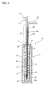
FIG 6 illustrates an apparatus for producing TCS according to a third embodiment of the present invention.
The apparatus for producingtrichlorosilane 51 is provided with an agitatingmember 54 formed by fixing asecond fin 53 to the periphery of acore bar 52 in the rawmaterial supplying tube 3. In this case, the rawmaterial supplying tube 3 is provided with thesame preheating unit 43 as in the second embodiment, the agitatingmember 54 has a length extending downward from the preheatingunit 43 to the vicinity of the inner bottom portion of the furnacemain body 5, and the front end portion thereof protrudes from thelower end opening 3a of the rawmaterial supplying tube 3.
In this case, the upper end of the agitatingmember 54 is supported by the wall of the rawmaterial supplying tube 3, and by removing the support to the upper end, the agitatingmember 54 can be moved vertically or rotated. Other configurations are the same as those of the first embodiment, and same elements are denoted the same reference numerals, so that a description thereof will be omitted. - In the apparatus for producing
trichlorosilane 51, the raw materials are supplied separately by thepolymer supplying system 11 and the hydrogenchloride supplying system 12 to the rawmaterial supplying tube 3, and are mixed with each other in the rawmaterial supplying tube 3 and introduced into thereaction chamber 13. The raw materials are effectively mixed with each other by the agitatingmember 54 provided in the rawmaterial supplying tube 3, so that it is possible to further enhance reaction efficiency in thereaction chamber 13 after the raw materials are introduced through thelower end opening 3a of the rawmaterial supplying tube 3.
In addition, the agitatingmember 54 can be moved vertically or rotated. Accordingly, in the case where silicon oxide is adhered to the vicinity of thelower end opening 3a of the rawmaterial supplying tube 3, by vertically moving or rotating the agitatingmember 54 during maintenance, the silicon oxide can be securely removed and silicon oxide deposited on the inner bottom portion of the furnacemain body 5 can be crushed. Therefore, it is possible to effectively perform the discharging of the silicon oxide by injecting the pressurized gas from the pressurizedgas injection tube 23 explained in the description of the apparatus for producing TCS of the first embodiment.
In addition, the agitatingmember 54 may also be provided only in the preheatingunit 43. -
FIGS. 7 and8 illustrate a modified example of a fin in the apparatus for producing TCS of the present invention.
Afin 61 has a structure of a so-called static mixer. That is, thefin 61 is configure by arrangingplural elements 62 in the longitudinal direction of the rawmaterial supplying tube 3, and the plural elements are formed by twisting rectangular plate members in a reverse direction at 180° and are alternately shifted at 90°. Due to thefin 61 having the static mixer structure, fluid is agitated and mixed in combination of a dividing operation of dividing the fluid into two flows whenever the fluid passes through thesingle element 62, a mixing (or converting) operation of moving the fluid from the center to the outside or from the outside to the center along the twisted surface of theelement 62, and a reversing operation of reversing the rotation direction at everyelement 62 for agitating.
By providing thefm 61 having the static mixer structure on the outer peripheral surface of the rawmaterial supplying tube 3, agitating and mixing in thereaction chamber 13 can be effectively performed, thereby further enhancing reaction efficiency.
In addition, in the case of thefin 61 having the static mixer structure, since thefin 61 is arranged to be shifted at 90°, at least two fins are needed. Depending on the capacity of the decomposing furnace, 5 to 20 fins may be provided. - In addition, in the apparatus for producing TCS of the embodiments, as illustrated in
FIG 9 , pluralspherical rolling members 65 made of stainless steel or the like may be provided on the inner bottom portion of the furnacemain body 5. InFIG. 9 , an example provided with the agitatingmember 54 of the third embodiment is shown. In this case, by vertically moving or rotating the agitatingmember 54, the rollingmembers 65 can be swung along theinner bottom surface 5b of the furnacemain body 5, so that the silicon oxide S can be reliably crushed by the rolling movement. - The present invention is not limited to the embodiments, and various modifications can be made without departing from the spirit and scope of the present invention.
For example, in the embodiments, the fin is fixed to the outer peripheral surface of the raw material supplying tube. However, the fin may be fixed to the inner peripheral surface of the furnace main body with a gap from the raw material supplying tube.
In addition, in order for the gas injected from the pressurizedgas injection tube 23 to easily reach theinner bottom surface 5b of the furnacemain body 5, a hole may be provided along the injection direction to thefin 14 existing in the injection direction.
In addition, in the second and third embodiments ofFIGS. 5 and6 , a fin for heat transfer may be provided to the outside of the section of the rawmaterial supplying tube 3 corresponding to the preheatingunit 43.
In addition, in the embodiments, polymer and hydrogen chloride are mixed with each other in the raw material supplying tube. However, a configuration may be employed in which the raw material supplying tube employs a double structure including an inner tube and an outer tube, hydrogen chloride is introduced through the inner tube, and a polymer is introduced between the inner and outer tubes. In the configuration, the polymer and hydrogen chloride are separately introduced in the raw material supplying tube, so that a reaction therebetween occurs after being introduced into the reaction chamber, thereby effectively preventing the raw material supplying tube from clogging up with silicon oxide. In this case, when the polymer flows in the outer tube while being in contact with the reaction chamber, the polymer is heated and gasified while flowing in the raw material supplying tube, thereby enabling an effective reaction in the reaction chamber.
In addition, in the embodiments, the furnace fluid discharge tube for discharging silicon oxide is provided in the end plate, however, may be provided to the bottom portion of the furnace main body.
In addition, in the embodiments, the fin is formed as a spiral shape. However, in place of such a continuous shape, plural fins may be arranged at intervals, and a straight or tubular shape may also be employed. For example, plural flat plate-shaped fins may be arranged at intervals in the longitudinal direction of the decomposing furnace, and in this case, the fins are shifted at predetermined angles such that portions thereof vertically overlap.
SiHCl3+2H2O→SiO2+H2+3HCl (iv)
SiCl4+2H2O→SiO2+4HCl (v)
Claims (7)
- An apparatus for producing trichlorosilane (1) which decomposes polymer containing high boiling point chlorosilanes generated in a polycrystalline silicon producing process, in a trichlorosilane producing or in a converting process, thereby producing trichlorosilane, the apparatus (1) comprising:a decomposing furnace (2) reacting a hydrogen chloride with the polymer at high temperatures for producing trichlorosilane;a heating unit (8) heating the inside of the decomposing furnace (2);a raw material supplying tube (3) for guiding the polymer and the hydrogen chloride to the inner bottom portion of the decomposing furnace (2) along the longitudinal direction of the decomposing furnace and supplying to the decomposing furnace (2) through a lower end opening (3a) of the raw material supplying tube (3);a reaction chamber (13) provided between the outer peripheral surface of the raw material supplying tube (3) and the inner peripheral surface of the decomposing furnace (2);a gas discharge tube (4) for discharging reaction gas from the top of the reaction chamber;a fin (14) which guides the polymer and the hydrogen chloride supplied from the lower end opening (3a) of the raw material supplying tube (3) to be agitated and rise upward and is formed integrally with at least one of the outer peripheral surface of the raw material supplying tube (3) or the inner peripheral surface of the decomposing furnace (2).
- The apparatus for producing trichlorosilane (1) according to claim 1, wherein the raw material supplying tube (3) is provided along the center axis (C) of the decomposing furnace (2) in the straight manner.
- The apparatus for producing trichlorosilane (1) according to claim 1 or 2,
wherein a polymer supplying system (11) and a hydrogen chloride supplying system (12) are connected to an upper section of the raw material supplying tube (3) which protrudes outward from the decomposing furnace (2), and
an agitating member (54) having a second fin (53) is inserted into the raw material supplying tube (3). - The apparatus for producing trichlorosilane (1) according to any one of claims 1 to 3, wherein the gas discharge tube(42) is formed in a double-tube structure to surround the periphery of the raw material supplying tube (3) on the outside of the decomposing furnace (2).
- The apparatus for producing trichlorosilane according to any one of claims 1 to 4, wherein the decomposing furnace is provided with a pressurized gas injection tube for injecting pressurized gas into the decomposing furnace and a furnace fluid discharge tube for discharging fluids in the furnace expelled by the pressurized gas.
- The apparatus for producing trichlorosilane (1) according to any one of claims 1 to 5, further comprising a number of spherical rolling members (65) provided on the inner bottom portion (5a) of the decomposing furnace (2).
- A method for producing trichlorosilan of introducing into a decomposing furnace (2) hydrogen chloride and polymer containing high boiling point chlorosilanes produced in a polycrystalline silicon producing process, in a trichlorosilane producing or in a converting process, and reacting them with each other at high temperature such that the polymer decomposes, thereby producing trichlorosilane, the method for producing trichlorosilan comprising:heating the decomposing furnace (2) and supplying the polymer and the hydrogen chloride from the top of the heated decomposing furnace (2) to be guided to the inner bottom portion of the decomposing furnace (2) while being gasified due to the preheating; andagitating a fluid mixture of the polymer and the hydrogen chloride and reacting them with each other while rising upward from the inner bottom portion (5b) in the decomposing furnace (2).
Applications Claiming Priority (1)
| Application Number | Priority Date | Filing Date | Title |
|---|---|---|---|
| JP2008201863 | 2008-08-05 |
Publications (2)
| Publication Number | Publication Date |
|---|---|
| EP2151416A1 true EP2151416A1 (en) | 2010-02-10 |
| EP2151416B1 EP2151416B1 (en) | 2017-03-01 |
Family
ID=41198637
Family Applications (1)
| Application Number | Title | Priority Date | Filing Date |
|---|---|---|---|
| EP09167090.1A Active EP2151416B1 (en) | 2008-08-05 | 2009-08-03 | Apparatus for producing trichlorosilane and method for producing trichlorosilane |
Country Status (7)
| Country | Link |
|---|---|
| US (3) | US8187552B2 (en) |
| EP (1) | EP2151416B1 (en) |
| JP (1) | JP5316290B2 (en) |
| KR (1) | KR101614542B1 (en) |
| CN (2) | CN101643213B (en) |
| MY (1) | MY172498A (en) |
| RU (1) | RU2496715C2 (en) |
Cited By (2)
| Publication number | Priority date | Publication date | Assignee | Title |
|---|---|---|---|---|
| WO2014173566A1 (en) * | 2013-04-24 | 2014-10-30 | Evonik Degussa Gmbh | Process for the preparation of hexachlorodisilane by cleavage of higher polychlorosilanes such as octachlorotrisilane |
| EP3483190A4 (en) * | 2016-07-08 | 2020-01-22 | C&Cpel Co., Ltd. | REACTOR FOR A METHOD FOR POLYMERIZING POLYOLEFINES WITH METALLOCEN-BASED SOLUTION |
Families Citing this family (15)
| Publication number | Priority date | Publication date | Assignee | Title |
|---|---|---|---|---|
| US20100264362A1 (en) * | 2008-07-01 | 2010-10-21 | Yongchae Chee | Method of producing trichlorosilane (TCS) rich Chlorosilane product stably from a fluidized gas phase reactor (FBR) and the structure of the reactor |
| JP5316291B2 (en) * | 2008-08-05 | 2013-10-16 | 三菱マテリアル株式会社 | Trichlorosilane production apparatus and production method |
| JP5316290B2 (en) * | 2008-08-05 | 2013-10-16 | 三菱マテリアル株式会社 | Trichlorosilane production apparatus and production method |
| JP5482265B2 (en) * | 2009-12-15 | 2014-05-07 | 三菱マテリアル株式会社 | Trichlorosilane production equipment |
| CN102190304B (en) * | 2010-03-08 | 2015-04-15 | 三菱综合材料株式会社 | Apparatus for producing trichlorosilane |
| US20110300050A1 (en) * | 2010-06-08 | 2011-12-08 | Memc Electronic Materials, Inc. | Trichlorosilane Vaporization System |
| JP5630412B2 (en) * | 2010-09-28 | 2014-11-26 | 三菱マテリアル株式会社 | Trichlorosilane production apparatus and production method |
| US8226920B1 (en) | 2011-01-07 | 2012-07-24 | Mitsubishi Polycrystalline Silicon America Corporation (MIPSA) | Apparatus and method for producing polycrystalline silicon having a reduced amount of boron compounds by venting the system with an inert gas |
| EP2688839B1 (en) * | 2011-03-25 | 2016-09-14 | Evonik Degussa GmbH | Use of silicon carbide tubes with a flanged or flared end |
| DE102011006116A1 (en) * | 2011-03-25 | 2012-09-27 | Evonik Degussa Gmbh | Use of burners with radiant tube in reactors for the reaction of chlorosilanes |
| US9732422B2 (en) | 2015-01-23 | 2017-08-15 | United Technologies Corporation | Method of coating metallic powder particles |
| KR101987129B1 (en) * | 2016-09-19 | 2019-06-10 | 한화케미칼 주식회사 | Fluidized bed reactor for composing trichlorosilane |
| RU2722027C1 (en) * | 2016-11-16 | 2020-05-26 | АйЭйчАй КОРПОРЕЙШН | Method of stabilizing chlorosilane polymer |
| CN113413627B (en) * | 2021-08-25 | 2021-11-09 | 山东蓝湾新材料有限公司 | Energy-saving separation device for high-molecular polymer intermediate |
| EP4624041A1 (en) * | 2024-03-28 | 2025-10-01 | Basell Polyolefine GmbH | Modular agitation means for agitating a gaseous stream of hydrocarbons |
Citations (9)
| Publication number | Priority date | Publication date | Assignee | Title |
|---|---|---|---|---|
| US4009751A (en) * | 1973-11-09 | 1977-03-01 | Slovenska Vysoka Skola Technika | Method of and apparatus for high intensity heat and/or mass transfer between two or more phases |
| US4590044A (en) * | 1982-10-07 | 1986-05-20 | Shell Oil Company | Multistage reactor for exothermic or endothermic chemical processes |
| JPH01188414A (en) | 1988-01-21 | 1989-07-27 | Osaka Titanium Co Ltd | Method for converting polymer to trichlorosilane in production of polycrystalline silicon |
| US6066759A (en) * | 1995-07-12 | 2000-05-23 | Basf Aktiengesellschaft | Process and device for preparing (cyclo)aliphatic biuret groups-containing polyisocyanates |
| US6291698B1 (en) * | 1999-04-22 | 2001-09-18 | Degussa Huels Ag | Process for preparing vinyl chlorosilanes |
| DE10032302A1 (en) * | 2000-07-04 | 2001-10-25 | Basf Ag | Tubular reactor used for carrying out heterogeneous catalyzed reactions, especially liquid phase oxidations has heat exchanger plates for transferring heat |
| WO2002012122A1 (en) | 2000-08-02 | 2002-02-14 | Mitsubishi Materials Polycrystalline Silicon Corporation | Process for producing disilicon hexachloride |
| JP2008201863A (en) | 2007-02-19 | 2008-09-04 | Hiroshima Pref Gov | Method for producing molded article of polylactic acid resin |
| EP2096082A1 (en) * | 2008-02-29 | 2009-09-02 | Mitsubishi Materials Corporation | Method and apparatus for manufacturing trichlorosilane |
Family Cites Families (26)
| Publication number | Priority date | Publication date | Assignee | Title |
|---|---|---|---|---|
| US1920632A (en) * | 1930-08-05 | 1933-08-01 | Koppers Co Inc | Contrivance for carrying out gas reactions at high temperatures |
| US2079017A (en) | 1933-10-18 | 1937-05-04 | Gen Chemical Corp | Apparatus for heating materials |
| US2855449A (en) * | 1954-03-12 | 1958-10-07 | Phillips Petroleum Co | Method of and apparatus for the acid-catalyzed alkylation of hydrocarbons |
| US3607125A (en) | 1968-12-30 | 1971-09-21 | Gen Electric | Reformer tube construction |
| US3945805A (en) * | 1974-04-18 | 1976-03-23 | Modine Manufacturing Company | Reactor-generator apparatus |
| US3945806A (en) * | 1974-04-18 | 1976-03-23 | Modine Manufacturing Company | Reactor-generator |
| CA1077197A (en) | 1975-03-24 | 1980-05-06 | Kazuhiko Kurimoto | Method for bulk polymerization of vinyl chloride |
| US4332296A (en) | 1980-08-01 | 1982-06-01 | Wayt Newell E | Well cleaning tool |
| JPS6131312A (en) * | 1984-07-20 | 1986-02-13 | Osaka Titanium Seizo Kk | Process and device for preparing polycrystalline silicon |
| JPH0649569B2 (en) * | 1985-11-25 | 1994-06-29 | 高純度シリコン株式会社 | Method and apparatus for producing trichlorosilane |
| SU1422571A1 (en) * | 1987-02-24 | 1999-08-10 | Государственный научно-исследовательский и проектный институт редкометаллической промышленности "Гиредмет" | METHOD OF PROCESSING THE CUBE RESIDUES OF TRICHLOROSYLAN PRODUCTION AND POLYCRYSTALLINE SILICON |
| US4969942A (en) | 1990-01-02 | 1990-11-13 | Ppg Industries, Inc. | Glass melter exhaust duct cleaning method and apparatus |
| JPH1149508A (en) * | 1997-06-03 | 1999-02-23 | Tokuyama Corp | Low waste polycrystalline silicon production method. |
| US6033290A (en) | 1998-09-29 | 2000-03-07 | Applied Materials, Inc. | Chemical mechanical polishing conditioner |
| DE10017168A1 (en) * | 2000-04-07 | 2001-10-11 | Bayer Ag | Continuous production of silane, useful in production of silicon for semiconductors, involves catalytic disproportionation of trichlorosilane over solid catalyst in 2 or more zones with intermediate condensation |
| US20020187096A1 (en) * | 2001-06-08 | 2002-12-12 | Kendig James Edward | Process for preparation of polycrystalline silicon |
| US7033561B2 (en) * | 2001-06-08 | 2006-04-25 | Dow Corning Corporation | Process for preparation of polycrystalline silicon |
| DE10309799A1 (en) | 2003-03-05 | 2004-09-23 | Sgl Acotec Gmbh | Method and device for producing hydrogen chloride |
| RU2274602C1 (en) * | 2004-08-16 | 2006-04-20 | Федеральное государственное унитарное предприятие "Государственный научно-исследовательский и проектный институт редкометаллической промышленности "Гиредмет" | Trichlorosilane production process |
| DE102004045245B4 (en) | 2004-09-17 | 2007-11-15 | Degussa Gmbh | Apparatus and process for the production of silanes |
| KR100783667B1 (en) | 2006-08-10 | 2007-12-07 | 한국화학연구원 | Method and apparatus for manufacturing particulate polycrystalline silicon |
| JP5205910B2 (en) * | 2006-10-31 | 2013-06-05 | 三菱マテリアル株式会社 | Trichlorosilane production equipment |
| CN101125654A (en) * | 2007-09-04 | 2008-02-20 | 浙江开化合成材料有限公司 | Large-scale fluidized bed reactor used for trichlorosilane production |
| US7814867B2 (en) * | 2008-02-26 | 2010-10-19 | Ex-Tar Technologies, Inc. | Reaction chamber for a direct contact rotating steam generator |
| JP5316291B2 (en) * | 2008-08-05 | 2013-10-16 | 三菱マテリアル株式会社 | Trichlorosilane production apparatus and production method |
| JP5316290B2 (en) * | 2008-08-05 | 2013-10-16 | 三菱マテリアル株式会社 | Trichlorosilane production apparatus and production method |
-
2009
- 2009-07-30 JP JP2009178450A patent/JP5316290B2/en not_active Expired - Fee Related
- 2009-08-03 US US12/461,148 patent/US8187552B2/en not_active Expired - Fee Related
- 2009-08-03 CN CN2009101638362A patent/CN101643213B/en active Active
- 2009-08-03 EP EP09167090.1A patent/EP2151416B1/en active Active
- 2009-08-03 KR KR1020090071355A patent/KR101614542B1/en active Active
- 2009-08-03 RU RU2009129709/05A patent/RU2496715C2/en active
- 2009-08-03 CN CN201310302831.XA patent/CN103496704B/en active Active
- 2009-08-03 MY MYPI20093194A patent/MY172498A/en unknown
-
2012
- 2012-01-09 US US13/345,864 patent/US8529844B2/en not_active Expired - Fee Related
- 2012-04-26 US US13/456,351 patent/US20120207661A1/en not_active Abandoned
Patent Citations (9)
| Publication number | Priority date | Publication date | Assignee | Title |
|---|---|---|---|---|
| US4009751A (en) * | 1973-11-09 | 1977-03-01 | Slovenska Vysoka Skola Technika | Method of and apparatus for high intensity heat and/or mass transfer between two or more phases |
| US4590044A (en) * | 1982-10-07 | 1986-05-20 | Shell Oil Company | Multistage reactor for exothermic or endothermic chemical processes |
| JPH01188414A (en) | 1988-01-21 | 1989-07-27 | Osaka Titanium Co Ltd | Method for converting polymer to trichlorosilane in production of polycrystalline silicon |
| US6066759A (en) * | 1995-07-12 | 2000-05-23 | Basf Aktiengesellschaft | Process and device for preparing (cyclo)aliphatic biuret groups-containing polyisocyanates |
| US6291698B1 (en) * | 1999-04-22 | 2001-09-18 | Degussa Huels Ag | Process for preparing vinyl chlorosilanes |
| DE10032302A1 (en) * | 2000-07-04 | 2001-10-25 | Basf Ag | Tubular reactor used for carrying out heterogeneous catalyzed reactions, especially liquid phase oxidations has heat exchanger plates for transferring heat |
| WO2002012122A1 (en) | 2000-08-02 | 2002-02-14 | Mitsubishi Materials Polycrystalline Silicon Corporation | Process for producing disilicon hexachloride |
| JP2008201863A (en) | 2007-02-19 | 2008-09-04 | Hiroshima Pref Gov | Method for producing molded article of polylactic acid resin |
| EP2096082A1 (en) * | 2008-02-29 | 2009-09-02 | Mitsubishi Materials Corporation | Method and apparatus for manufacturing trichlorosilane |
Cited By (5)
| Publication number | Priority date | Publication date | Assignee | Title |
|---|---|---|---|---|
| WO2014173566A1 (en) * | 2013-04-24 | 2014-10-30 | Evonik Degussa Gmbh | Process for the preparation of hexachlorodisilane by cleavage of higher polychlorosilanes such as octachlorotrisilane |
| CN105121343A (en) * | 2013-04-24 | 2015-12-02 | 赢创德固赛有限公司 | Process for the preparation of hexachlorodisilane by cleavage of higher polychlorosilanes such as octachlorotrisilane |
| US9758383B2 (en) | 2013-04-24 | 2017-09-12 | Evonik Degussa Gmbh | Process for the preparation of hexachlorodisilane by cleavage of higher polychlorosilanes such as octachlorotrisilane |
| EP3483190A4 (en) * | 2016-07-08 | 2020-01-22 | C&Cpel Co., Ltd. | REACTOR FOR A METHOD FOR POLYMERIZING POLYOLEFINES WITH METALLOCEN-BASED SOLUTION |
| US11219877B2 (en) | 2016-07-08 | 2022-01-11 | C&Cpel Co., Ltd. | Reactor for a metallocene catalyst-based solution polymerization process for preparing polyolefin polymers |
Also Published As
| Publication number | Publication date |
|---|---|
| EP2151416B1 (en) | 2017-03-01 |
| CN103496704B (en) | 2015-10-21 |
| US8529844B2 (en) | 2013-09-10 |
| RU2496715C2 (en) | 2013-10-27 |
| CN103496704A (en) | 2014-01-08 |
| JP5316290B2 (en) | 2013-10-16 |
| RU2009129709A (en) | 2011-02-10 |
| KR101614542B1 (en) | 2016-04-21 |
| US20100034722A1 (en) | 2010-02-11 |
| CN101643213B (en) | 2013-08-21 |
| MY172498A (en) | 2019-11-27 |
| US20120207661A1 (en) | 2012-08-16 |
| CN101643213A (en) | 2010-02-10 |
| JP2010059042A (en) | 2010-03-18 |
| US20120107190A1 (en) | 2012-05-03 |
| KR20100017062A (en) | 2010-02-16 |
| US8187552B2 (en) | 2012-05-29 |
Similar Documents
| Publication | Publication Date | Title |
|---|---|---|
| EP2151416B1 (en) | Apparatus for producing trichlorosilane and method for producing trichlorosilane | |
| JP5621957B2 (en) | Method and apparatus for producing trichlorosilane | |
| US8980191B2 (en) | Method and apparatus for manufacturing trichlorosilane | |
| KR101388323B1 (en) | Process for producing trichlorosilane and trichlorosilane producing apparatus | |
| TWI576560B (en) | Shell and tube heat exchangers and methods of using such heat exchangers | |
| CN102272047A (en) | Manufacturing method of polysilicon | |
| CN107555438A (en) | Polysilicon is prepared in the method and system of basic closed loop | |
| KR101055751B1 (en) | Method and apparatus for producing trichlorosilane using catalyst and reaction heat | |
| KR101768279B1 (en) | Apparatus and method for producing polycrystalline silicon using horizontal reactor | |
| WO2014100705A1 (en) | Conserved off gas recovery systems and processes | |
| CN102196995B (en) | The preparation method of trichlorosilane and Application way | |
| CN217341280U (en) | Device for preparing chlorosilane | |
| US20120213687A1 (en) | Method for manufacturing trichlorosilane | |
| JP5754499B2 (en) | Trichlorosilane production method | |
| JP5630412B2 (en) | Trichlorosilane production apparatus and production method | |
| ES2350559A1 (en) | Procedure for the use of light residues in a high purity silicon production plant. (Machine-translation by Google Translate, not legally binding) |
Legal Events
| Date | Code | Title | Description |
|---|---|---|---|
| PUAI | Public reference made under article 153(3) epc to a published international application that has entered the european phase |
Free format text: ORIGINAL CODE: 0009012 |
|
| AK | Designated contracting states |
Kind code of ref document: A1 Designated state(s): AT BE BG CH CY CZ DE DK EE ES FI FR GB GR HR HU IE IS IT LI LT LU LV MC MK MT NL NO PL PT RO SE SI SK SM TR |
|
| AX | Request for extension of the european patent |
Extension state: AL BA RS |
|
| 17P | Request for examination filed |
Effective date: 20100806 |
|
| 17Q | First examination report despatched |
Effective date: 20110128 |
|
| GRAP | Despatch of communication of intention to grant a patent |
Free format text: ORIGINAL CODE: EPIDOSNIGR1 |
|
| STAA | Information on the status of an ep patent application or granted ep patent |
Free format text: STATUS: GRANT OF PATENT IS INTENDED |
|
| INTG | Intention to grant announced |
Effective date: 20161107 |
|
| RIC1 | Information provided on ipc code assigned before grant |
Ipc: B01J 19/18 20060101ALI20161025BHEP Ipc: B01J 19/24 20060101ALI20161025BHEP Ipc: C01B 33/107 20060101AFI20161025BHEP Ipc: B01J 19/00 20060101ALI20161025BHEP |
|
| GRAS | Grant fee paid |
Free format text: ORIGINAL CODE: EPIDOSNIGR3 |
|
| GRAA | (expected) grant |
Free format text: ORIGINAL CODE: 0009210 |
|
| STAA | Information on the status of an ep patent application or granted ep patent |
Free format text: STATUS: THE PATENT HAS BEEN GRANTED |
|
| AK | Designated contracting states |
Kind code of ref document: B1 Designated state(s): AT BE BG CH CY CZ DE DK EE ES FI FR GB GR HR HU IE IS IT LI LT LU LV MC MK MT NL NO PL PT RO SE SI SK SM TR |
|
| REG | Reference to a national code |
Ref country code: GB Ref legal event code: FG4D |
|
| REG | Reference to a national code |
Ref country code: CH Ref legal event code: EP Ref country code: AT Ref legal event code: REF Ref document number: 871049 Country of ref document: AT Kind code of ref document: T Effective date: 20170315 |
|
| REG | Reference to a national code |
Ref country code: IE Ref legal event code: FG4D |
|
| REG | Reference to a national code |
Ref country code: DE Ref legal event code: R096 Ref document number: 602009044419 Country of ref document: DE |
|
| REG | Reference to a national code |
Ref country code: NL Ref legal event code: MP Effective date: 20170301 |
|
| REG | Reference to a national code |
Ref country code: LT Ref legal event code: MG4D |
|
| REG | Reference to a national code |
Ref country code: AT Ref legal event code: MK05 Ref document number: 871049 Country of ref document: AT Kind code of ref document: T Effective date: 20170301 |
|
| PG25 | Lapsed in a contracting state [announced via postgrant information from national office to epo] |
Ref country code: NO Free format text: LAPSE BECAUSE OF FAILURE TO SUBMIT A TRANSLATION OF THE DESCRIPTION OR TO PAY THE FEE WITHIN THE PRESCRIBED TIME-LIMIT Effective date: 20170601 Ref country code: FI Free format text: LAPSE BECAUSE OF FAILURE TO SUBMIT A TRANSLATION OF THE DESCRIPTION OR TO PAY THE FEE WITHIN THE PRESCRIBED TIME-LIMIT Effective date: 20170301 Ref country code: HR Free format text: LAPSE BECAUSE OF FAILURE TO SUBMIT A TRANSLATION OF THE DESCRIPTION OR TO PAY THE FEE WITHIN THE PRESCRIBED TIME-LIMIT Effective date: 20170301 Ref country code: LT Free format text: LAPSE BECAUSE OF FAILURE TO SUBMIT A TRANSLATION OF THE DESCRIPTION OR TO PAY THE FEE WITHIN THE PRESCRIBED TIME-LIMIT Effective date: 20170301 Ref country code: GR Free format text: LAPSE BECAUSE OF FAILURE TO SUBMIT A TRANSLATION OF THE DESCRIPTION OR TO PAY THE FEE WITHIN THE PRESCRIBED TIME-LIMIT Effective date: 20170602 |
|
| PG25 | Lapsed in a contracting state [announced via postgrant information from national office to epo] |
Ref country code: SE Free format text: LAPSE BECAUSE OF FAILURE TO SUBMIT A TRANSLATION OF THE DESCRIPTION OR TO PAY THE FEE WITHIN THE PRESCRIBED TIME-LIMIT Effective date: 20170301 Ref country code: BG Free format text: LAPSE BECAUSE OF FAILURE TO SUBMIT A TRANSLATION OF THE DESCRIPTION OR TO PAY THE FEE WITHIN THE PRESCRIBED TIME-LIMIT Effective date: 20170601 Ref country code: LV Free format text: LAPSE BECAUSE OF FAILURE TO SUBMIT A TRANSLATION OF THE DESCRIPTION OR TO PAY THE FEE WITHIN THE PRESCRIBED TIME-LIMIT Effective date: 20170301 Ref country code: AT Free format text: LAPSE BECAUSE OF FAILURE TO SUBMIT A TRANSLATION OF THE DESCRIPTION OR TO PAY THE FEE WITHIN THE PRESCRIBED TIME-LIMIT Effective date: 20170301 Ref country code: ES Free format text: LAPSE BECAUSE OF FAILURE TO SUBMIT A TRANSLATION OF THE DESCRIPTION OR TO PAY THE FEE WITHIN THE PRESCRIBED TIME-LIMIT Effective date: 20170301 |
|
| PG25 | Lapsed in a contracting state [announced via postgrant information from national office to epo] |
Ref country code: NL Free format text: LAPSE BECAUSE OF FAILURE TO SUBMIT A TRANSLATION OF THE DESCRIPTION OR TO PAY THE FEE WITHIN THE PRESCRIBED TIME-LIMIT Effective date: 20170301 |
|
| PG25 | Lapsed in a contracting state [announced via postgrant information from national office to epo] |
Ref country code: RO Free format text: LAPSE BECAUSE OF FAILURE TO SUBMIT A TRANSLATION OF THE DESCRIPTION OR TO PAY THE FEE WITHIN THE PRESCRIBED TIME-LIMIT Effective date: 20170301 Ref country code: SK Free format text: LAPSE BECAUSE OF FAILURE TO SUBMIT A TRANSLATION OF THE DESCRIPTION OR TO PAY THE FEE WITHIN THE PRESCRIBED TIME-LIMIT Effective date: 20170301 Ref country code: CZ Free format text: LAPSE BECAUSE OF FAILURE TO SUBMIT A TRANSLATION OF THE DESCRIPTION OR TO PAY THE FEE WITHIN THE PRESCRIBED TIME-LIMIT Effective date: 20170301 Ref country code: IT Free format text: LAPSE BECAUSE OF FAILURE TO SUBMIT A TRANSLATION OF THE DESCRIPTION OR TO PAY THE FEE WITHIN THE PRESCRIBED TIME-LIMIT Effective date: 20170301 Ref country code: EE Free format text: LAPSE BECAUSE OF FAILURE TO SUBMIT A TRANSLATION OF THE DESCRIPTION OR TO PAY THE FEE WITHIN THE PRESCRIBED TIME-LIMIT Effective date: 20170301 |
|
| PG25 | Lapsed in a contracting state [announced via postgrant information from national office to epo] |
Ref country code: PT Free format text: LAPSE BECAUSE OF FAILURE TO SUBMIT A TRANSLATION OF THE DESCRIPTION OR TO PAY THE FEE WITHIN THE PRESCRIBED TIME-LIMIT Effective date: 20170703 Ref country code: PL Free format text: LAPSE BECAUSE OF FAILURE TO SUBMIT A TRANSLATION OF THE DESCRIPTION OR TO PAY THE FEE WITHIN THE PRESCRIBED TIME-LIMIT Effective date: 20170301 Ref country code: SM Free format text: LAPSE BECAUSE OF FAILURE TO SUBMIT A TRANSLATION OF THE DESCRIPTION OR TO PAY THE FEE WITHIN THE PRESCRIBED TIME-LIMIT Effective date: 20170301 Ref country code: IS Free format text: LAPSE BECAUSE OF FAILURE TO SUBMIT A TRANSLATION OF THE DESCRIPTION OR TO PAY THE FEE WITHIN THE PRESCRIBED TIME-LIMIT Effective date: 20170701 |
|
| REG | Reference to a national code |
Ref country code: DE Ref legal event code: R097 Ref document number: 602009044419 Country of ref document: DE |
|
| PLBE | No opposition filed within time limit |
Free format text: ORIGINAL CODE: 0009261 |
|
| STAA | Information on the status of an ep patent application or granted ep patent |
Free format text: STATUS: NO OPPOSITION FILED WITHIN TIME LIMIT |
|
| PG25 | Lapsed in a contracting state [announced via postgrant information from national office to epo] |
Ref country code: DK Free format text: LAPSE BECAUSE OF FAILURE TO SUBMIT A TRANSLATION OF THE DESCRIPTION OR TO PAY THE FEE WITHIN THE PRESCRIBED TIME-LIMIT Effective date: 20170301 |
|
| 26N | No opposition filed |
Effective date: 20171204 |
|
| PG25 | Lapsed in a contracting state [announced via postgrant information from national office to epo] |
Ref country code: SI Free format text: LAPSE BECAUSE OF FAILURE TO SUBMIT A TRANSLATION OF THE DESCRIPTION OR TO PAY THE FEE WITHIN THE PRESCRIBED TIME-LIMIT Effective date: 20170301 |
|
| REG | Reference to a national code |
Ref country code: CH Ref legal event code: PL |
|
| PG25 | Lapsed in a contracting state [announced via postgrant information from national office to epo] |
Ref country code: MC Free format text: LAPSE BECAUSE OF FAILURE TO SUBMIT A TRANSLATION OF THE DESCRIPTION OR TO PAY THE FEE WITHIN THE PRESCRIBED TIME-LIMIT Effective date: 20170301 |
|
| GBPC | Gb: european patent ceased through non-payment of renewal fee |
Effective date: 20170803 |
|
| PG25 | Lapsed in a contracting state [announced via postgrant information from national office to epo] |
Ref country code: CH Free format text: LAPSE BECAUSE OF NON-PAYMENT OF DUE FEES Effective date: 20170831 Ref country code: LI Free format text: LAPSE BECAUSE OF NON-PAYMENT OF DUE FEES Effective date: 20170831 |
|
| REG | Reference to a national code |
Ref country code: BE Ref legal event code: MM Effective date: 20170831 |
|
| REG | Reference to a national code |
Ref country code: FR Ref legal event code: ST Effective date: 20180430 |
|
| REG | Reference to a national code |
Ref country code: IE Ref legal event code: MM4A |
|
| PG25 | Lapsed in a contracting state [announced via postgrant information from national office to epo] |
Ref country code: LU Free format text: LAPSE BECAUSE OF NON-PAYMENT OF DUE FEES Effective date: 20170803 |
|
| PG25 | Lapsed in a contracting state [announced via postgrant information from national office to epo] |
Ref country code: IE Free format text: LAPSE BECAUSE OF NON-PAYMENT OF DUE FEES Effective date: 20170803 Ref country code: GB Free format text: LAPSE BECAUSE OF NON-PAYMENT OF DUE FEES Effective date: 20170803 |
|
| PG25 | Lapsed in a contracting state [announced via postgrant information from national office to epo] |
Ref country code: FR Free format text: LAPSE BECAUSE OF NON-PAYMENT OF DUE FEES Effective date: 20170831 Ref country code: BE Free format text: LAPSE BECAUSE OF NON-PAYMENT OF DUE FEES Effective date: 20170831 |
|
| PG25 | Lapsed in a contracting state [announced via postgrant information from national office to epo] |
Ref country code: MT Free format text: LAPSE BECAUSE OF NON-PAYMENT OF DUE FEES Effective date: 20170803 |
|
| PG25 | Lapsed in a contracting state [announced via postgrant information from national office to epo] |
Ref country code: HU Free format text: LAPSE BECAUSE OF FAILURE TO SUBMIT A TRANSLATION OF THE DESCRIPTION OR TO PAY THE FEE WITHIN THE PRESCRIBED TIME-LIMIT; INVALID AB INITIO Effective date: 20090803 |
|
| PG25 | Lapsed in a contracting state [announced via postgrant information from national office to epo] |
Ref country code: CY Free format text: LAPSE BECAUSE OF NON-PAYMENT OF DUE FEES Effective date: 20170301 |
|
| PG25 | Lapsed in a contracting state [announced via postgrant information from national office to epo] |
Ref country code: MK Free format text: LAPSE BECAUSE OF FAILURE TO SUBMIT A TRANSLATION OF THE DESCRIPTION OR TO PAY THE FEE WITHIN THE PRESCRIBED TIME-LIMIT Effective date: 20170301 |
|
| PG25 | Lapsed in a contracting state [announced via postgrant information from national office to epo] |
Ref country code: TR Free format text: LAPSE BECAUSE OF FAILURE TO SUBMIT A TRANSLATION OF THE DESCRIPTION OR TO PAY THE FEE WITHIN THE PRESCRIBED TIME-LIMIT Effective date: 20170301 |
|
| REG | Reference to a national code |
Ref country code: DE Ref legal event code: R081 Ref document number: 602009044419 Country of ref document: DE Owner name: HIGH-PURITY SILICON CORP., YOKKAICHI-SHI, JP Free format text: FORMER OWNER: MITSUBISHI MATERIALS CORPORATION, TOKYO, JP |
|
| PGFP | Annual fee paid to national office [announced via postgrant information from national office to epo] |
Ref country code: DE Payment date: 20250820 Year of fee payment: 17 |