EP2151407A2 - Right angle turn (RAT) module for conveying multi-sheet collations - Google Patents
Right angle turn (RAT) module for conveying multi-sheet collations Download PDFInfo
- Publication number
- EP2151407A2 EP2151407A2 EP09009279A EP09009279A EP2151407A2 EP 2151407 A2 EP2151407 A2 EP 2151407A2 EP 09009279 A EP09009279 A EP 09009279A EP 09009279 A EP09009279 A EP 09009279A EP 2151407 A2 EP2151407 A2 EP 2151407A2
- Authority
- EP
- European Patent Office
- Prior art keywords
- directing
- sheet
- opposed
- right angle
- belt segments
- Prior art date
- Legal status (The legal status is an assumption and is not a legal conclusion. Google has not performed a legal analysis and makes no representation as to the accuracy of the status listed.)
- Granted
Links
- 238000005096 rolling process Methods 0.000 claims abstract description 27
- 230000007246 mechanism Effects 0.000 claims abstract description 11
- 230000000694 effects Effects 0.000 claims abstract description 10
- 238000000034 method Methods 0.000 claims description 9
- 238000003780 insertion Methods 0.000 claims description 5
- 230000037431 insertion Effects 0.000 claims description 5
- 230000003028 elevating effect Effects 0.000 claims 1
- 238000011144 upstream manufacturing Methods 0.000 description 6
- 230000001154 acute effect Effects 0.000 description 5
- 238000006073 displacement reaction Methods 0.000 description 3
- 238000004519 manufacturing process Methods 0.000 description 3
- 230000002093 peripheral effect Effects 0.000 description 2
- JOYRKODLDBILNP-UHFFFAOYSA-N Ethyl urethane Chemical compound CCOC(N)=O JOYRKODLDBILNP-UHFFFAOYSA-N 0.000 description 1
- 230000000712 assembly Effects 0.000 description 1
- 238000000429 assembly Methods 0.000 description 1
- 238000009434 installation Methods 0.000 description 1
- 230000003993 interaction Effects 0.000 description 1
- 230000003068 static effect Effects 0.000 description 1
- 238000011282 treatment Methods 0.000 description 1
Images



Classifications
-
- B—PERFORMING OPERATIONS; TRANSPORTING
- B65—CONVEYING; PACKING; STORING; HANDLING THIN OR FILAMENTARY MATERIAL
- B65H—HANDLING THIN OR FILAMENTARY MATERIAL, e.g. SHEETS, WEBS, CABLES
- B65H29/00—Delivering or advancing articles from machines; Advancing articles to or into piles
- B65H29/12—Delivering or advancing articles from machines; Advancing articles to or into piles by means of the nip between two, or between two sets of, moving tapes or bands or rollers
-
- B—PERFORMING OPERATIONS; TRANSPORTING
- B65—CONVEYING; PACKING; STORING; HANDLING THIN OR FILAMENTARY MATERIAL
- B65H—HANDLING THIN OR FILAMENTARY MATERIAL, e.g. SHEETS, WEBS, CABLES
- B65H31/00—Pile receivers
- B65H31/30—Arrangements for removing completed piles
- B65H31/3027—Arrangements for removing completed piles by the nip between moving belts or rollers
-
- B—PERFORMING OPERATIONS; TRANSPORTING
- B65—CONVEYING; PACKING; STORING; HANDLING THIN OR FILAMENTARY MATERIAL
- B65H—HANDLING THIN OR FILAMENTARY MATERIAL, e.g. SHEETS, WEBS, CABLES
- B65H2220/00—Function indicators
- B65H2220/09—Function indicators indicating that several of an entity are present
-
- B—PERFORMING OPERATIONS; TRANSPORTING
- B65—CONVEYING; PACKING; STORING; HANDLING THIN OR FILAMENTARY MATERIAL
- B65H—HANDLING THIN OR FILAMENTARY MATERIAL, e.g. SHEETS, WEBS, CABLES
- B65H2301/00—Handling processes for sheets or webs
- B65H2301/30—Orientation, displacement, position of the handled material
- B65H2301/33—Modifying, selecting, changing orientation
- B65H2301/332—Turning, overturning
- B65H2301/3321—Turning, overturning kinetic therefor
- B65H2301/33212—Turning, overturning kinetic therefor about an axis parallel to the direction of displacement of material
-
- B—PERFORMING OPERATIONS; TRANSPORTING
- B65—CONVEYING; PACKING; STORING; HANDLING THIN OR FILAMENTARY MATERIAL
- B65H—HANDLING THIN OR FILAMENTARY MATERIAL, e.g. SHEETS, WEBS, CABLES
- B65H2301/00—Handling processes for sheets or webs
- B65H2301/30—Orientation, displacement, position of the handled material
- B65H2301/33—Modifying, selecting, changing orientation
- B65H2301/332—Turning, overturning
- B65H2301/3322—Turning, overturning according to a determined angle
- B65H2301/33222—90°
-
- B—PERFORMING OPERATIONS; TRANSPORTING
- B65—CONVEYING; PACKING; STORING; HANDLING THIN OR FILAMENTARY MATERIAL
- B65H—HANDLING THIN OR FILAMENTARY MATERIAL, e.g. SHEETS, WEBS, CABLES
- B65H2301/00—Handling processes for sheets or webs
- B65H2301/30—Orientation, displacement, position of the handled material
- B65H2301/34—Modifying, selecting, changing direction of displacement
- B65H2301/341—Modifying, selecting, changing direction of displacement without change of plane of displacement
- B65H2301/3411—Right angle arrangement, i.e. 90 degrees
- B65H2301/34112—Right angle arrangement, i.e. 90 degrees changing leading edge
-
- B—PERFORMING OPERATIONS; TRANSPORTING
- B65—CONVEYING; PACKING; STORING; HANDLING THIN OR FILAMENTARY MATERIAL
- B65H—HANDLING THIN OR FILAMENTARY MATERIAL, e.g. SHEETS, WEBS, CABLES
- B65H2301/00—Handling processes for sheets or webs
- B65H2301/30—Orientation, displacement, position of the handled material
- B65H2301/34—Modifying, selecting, changing direction of displacement
- B65H2301/342—Modifying, selecting, changing direction of displacement with change of plane of displacement
-
- B—PERFORMING OPERATIONS; TRANSPORTING
- B65—CONVEYING; PACKING; STORING; HANDLING THIN OR FILAMENTARY MATERIAL
- B65H—HANDLING THIN OR FILAMENTARY MATERIAL, e.g. SHEETS, WEBS, CABLES
- B65H2301/00—Handling processes for sheets or webs
- B65H2301/40—Type of handling process
- B65H2301/42—Piling, depiling, handling piles
- B65H2301/422—Handling piles, sets or stacks of articles
- B65H2301/4226—Delivering, advancing piles
- B65H2301/42262—Delivering, advancing piles by acting on surface of outermost articles of the pile, e.g. in nip between pair of belts or rollers
-
- B—PERFORMING OPERATIONS; TRANSPORTING
- B65—CONVEYING; PACKING; STORING; HANDLING THIN OR FILAMENTARY MATERIAL
- B65H—HANDLING THIN OR FILAMENTARY MATERIAL, e.g. SHEETS, WEBS, CABLES
- B65H2404/00—Parts for transporting or guiding the handled material
- B65H2404/20—Belts
- B65H2404/25—Driving or guiding arrangements
- B65H2404/256—Arrangement of endless belt
- B65H2404/2561—Arrangement of endless belt twisted around an axis parallel the transport direction
-
- B—PERFORMING OPERATIONS; TRANSPORTING
- B65—CONVEYING; PACKING; STORING; HANDLING THIN OR FILAMENTARY MATERIAL
- B65H—HANDLING THIN OR FILAMENTARY MATERIAL, e.g. SHEETS, WEBS, CABLES
- B65H2404/00—Parts for transporting or guiding the handled material
- B65H2404/60—Other elements in face contact with handled material
- B65H2404/61—Longitudinally-extending strips, tubes, plates, or wires
- B65H2404/612—Longitudinally-extending strips, tubes, plates, or wires and shaped for curvilinear transport path
Definitions
- the present invention relates to apparatus for conveying sheet material, and more particularly, to a new and useful Right Angle Turn (RAT) module which is operative to re-direct a collation of sheet material from an upstream module to a downstream module of a mailpiece fabrication device.
- RAT Right Angle Turn
- Mailpiece creation systems such as mailpiece inserters are typically used by organizations such as banks, insurance companies, and utility companies to periodically produce a large volume of mailpieces, e.g., monthly billing or shareholders income/dividend statements.
- mailpiece inserters are analogous to automated assembly equipment inasmuch as sheets, inserts and envelopes are conveyed along a feed path and assembled in or at various modules of the mailpiece inserter. That is, the various modules work cooperatively to process the sheets until a finished mailpiece is produced.
- a mailpiece inserter While the exact configuration of each mailpiece inserter depends upon the needs of a particular customer/installation, a mailpiece inserter will frequently employ modules for re-directing the feed path, e.g., ninety degrees, to accommodate the configuration of a customer's facility. More specifically, a mailpiece inserter may employ one or more Right Angle Turn (RAT) modules to produce an L- or U-shaped inserter feed path.
- RAT Right Angle Turn
- a RAT module typically comprises one or more roller assemblies, i.e., a drive and idler roller pair, disposed at an acute angle relative to the direction of the feed path upon receipt by the roller(s).
- the roller assembly is disposed at an angle of approximately forty-five (45) degrees such that the sheet material will enter the module by contacting the peripheral surface of the roller assembly along a first line of tangency, i.e., to one side of the drive roller, and exit the module after being driven about the peripheral surface of the drive roller, to a second line of tangency along the other side thereof. Consequently, the sheet material is redirected ninety (90) degrees.
- RAT modules of the prior art have proven successful and reliable for re-directing individual sheets of material, i.e., a single sheet of material captured between the drive and idler rollers
- such modules are significantly less effective and/or reliable when re-directing multi-sheet collations. That is, when passing multiple sheets of material through a RAT module of the prior art, the sheets exhibit a propensity to skew, become misaligned, and/or do not maintain edge registration. Consequently, difficulties arise when inserting such collations into a mailpiece envelope. Specifically, insertion becomes difficult when attempting to fill an envelope with a collation which is skewed inasmuch as the internal side edges of the envelope pocket are no longer parallel to the side edges of the collation. Furthermore, when edge registration of the individual sheets of a collation is not maintained, i.e., are misaligned, the sheet collation may be oversized as compared to the pocket dimension of the envelope. Consequently, the envelope cannot be filled.
- RAT Right Angle Turn
- a Right Angle Turn (RAT) module for processing multi-sheet collations in a mailpiece fabrication device.
- the RAT module includes opposed belt segments defining a conveyance channel for capturing multi-sheet collations therebetween and for conveying multi-sheet collations from an input and to an output end of the conveyance channel.
- the opposed belt segments defining a first re-directing bend, a second re-directing bend and a twist section disposed therebetween.
- the first re-directing bend includes a rolling element for re-directing the opposed belt segments about a first axis of rotation while the second re-directing bend includes a rolling element for re-directing the opposed belt segments about a second axis of rotation.
- the first and second axes of rotation are orthogonal to each other so as to effect a twist section therebetween.
- the RAT module additionally includes a mechanism for driving the opposed belt segments about the first and second re-directing bends to convey the multi-sheet collations from the input to output ends and effect a right angle turn of the multi-sheet collations.
- Figure 1 is a schematic view of a portion of a mailpiece inserter including a Right Angle Turn (RAT) module according to the present invention interposed between an upstream module and a downstream module of the mailpiece inserter.
- RAT Right Angle Turn
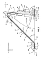
- Figure 2 is a profile view of the relevant portions of a Right Angle Turn (RAT) module according to the teachings of the present invention including opposed belt segments defining a channel for conveying a multi-sheet collation through first and second re-directing bends and a twist section disposed between the re-directing bends.
- RAT Right Angle Turn
- Figure 3 is a view taken substantially along line 3 - 3 of Fig. 2 to more fully illustrate the conveyance channel and the capability to re-direct the multi-sheet collation through a ninety-degree turn, i.e., from the input to output ends of the RAT module.
- Figure 4 is a top view taken substantially along line 4 - 4 of Fig. 2 to more fully illustrate the utility of the twist section to re-direct the multi-sheet collation through the ninety-degree turn of the RAT module.
- Figure 5 depicts an alternate embodiment of the present invention wherein a single conveyance belt synchronizes the opposed belt segments of the conveyance channel to prevent misalignment of the sheet collation.
- Figure 6 depicts another alternate embodiment of the present invention wherein a pair of anti-skew guides is disposed laterally of the conveyance channel to guide the multi-sheet collation through the twist section of the conveyance channel and prevent skewing of the sheet collation.
- Figure 7 depicts a sectional view taken substantially along line 7 - 7 of Fig. 6 .
- the present invention will be described in the context of a mailpiece inserter for re-directing sheet material through a right angle, or ninety-degree turn. Furthermore, the invention is generally applicable to any sheet material handling device such as may be used in the fabrication of mailpieces, e.g., sorters, facer/cancellers, feeders, etc. That is, the Right Angle Turn (RAT) module of the present invention is described in the context of a mailpiece inserter merely for illustration purposes and should not be construed as limiting the scope of the appended claims.
- RAT Right Angle Turn
- a mailpiece inserter 8 includes a RAT module 10 of the present invention interposed between an upstream module 12 and a downstream module 14.
- the modules 12, 14 are arranged such that the respective feed paths for conveying sheet material 20 are orthogonal, i.e., at right angles to each other.
- this arrangement of the various stations/modules 12, 14 may be influenced by the available space requirements of a customer and/or may be advantageous for ease of operator access to the various inserter modules.
- the upstream module 12 may be a folding module operative to fold a sheet material collation stack sheet material.
- the downstream module 14 may be any one of a variety of system stations/modules including an insertion module operative to insert a folded sheet collation into a mailpiece envelope.
- the function of the upstream and downstream modules 12 and 14 are irrelevant to the structure and function of the present invention, except that the feed paths and for conveying sheet material (denoted by arrows P 12 and P 14 ) are at right angles, i.e., orthogonal, to each other.
- the RAT module 10 includes opposed belt segments 22, 24 which define a channel 26 therebetween for conveying a multi-sheet collation 28 from an input end 30 to an output end 32.
- the opposed belt segments 22, 24 are formed from a urethane material and have a high coefficient of static friction, i.e., sufficient to capture and convey multi-sheet collations without slippage or inadvertent displacement.
- the phrase "opposed belts" are intended to describe the orientation and face-to-face relation of a conveyance belt rather than a meaning which implies a plurality of belts.
- the invention contemplates the use of both (i) a single continuous belt which is recurved to define the conveyance channel 26 and (ii) a pair of belts, each forming a continuous loop, which cooperates to form the conveyance channel 26.
- This aspect of the invention will be described in subsequent paragraphs.
- each of the opposed belt segments 22, 24 are shown as being broken away at the input and output ends 32, it should be appreciated that the belts 22, 24 complete a continuous closed loop, whether individually or in combination, and are driven by a conventional rotary drive mechanism.
- the mechanism for driving the opposed belt segments 22, 24 and mechanism for synchronizing the rate of displacement, or speed, of each will also be discussed in further detail hereinafter.
- the input end 30 is defined by a first pair of rolling elements 34a, 34b which, in combination with the belts 22, 24, form an input throat 30T for receiving the multi-sheet collation 28, e.g., from the upstream module 12.
- the output end 32 is similarly defined by a second pair of rolling elements 38a, 38b which, in combination with the belts 22, 24, define an exit interface 32E for conveying the multi-sheet collation 28 to the downstream module 14.
- the input and output ends 30, 32 and, consequently, the throat 30T and exit interface 32E are essentially coincident and co-planar, along line 36L and plane 36P. It should be appreciated, however, that input and output ends 30, 32 may differ in elevation and alignment.
- the opposed belt segments 22, 24 are disposed over and guided by various additional rolling elements to define an inclined section 40, a first re-directing bend 42, a vertical twist section 44 and a second re-directing bend 46. More, specifically, a rolling element 48 rotates about an axis of rotation 48A to direct the opposed belt segments 22, 24 up the inclined section 40 toward the first re-directing bend 42.
- the inclined section 40 defines an acute angle ⁇ of about forty-five (45) degrees, though this angle may vary depending upon the available space within the RAT module 10.
- the first re-directing bend 42 is effected by a rolling element 52 having a first axis of rotation 52A which redirects the opposed belt segments 22, 24 and, the course/direction of the sheet collation 28.
- the first re-directing bend 42 furthermore, re-directs the opposed belt segments 22, 24, and the course/direction of the sheet collation, over an obtuse angle ⁇ of about one-hundred and thirty-five (135) degrees.
- the first re-directing bend 42 directs the opposed belt segments 22, 24, vertically downwardly toward the second re-directing bend 46.
- the axis of rotation 48A is substantially parallel to the rotational axis 52A such that opposed belt segments 22, 24, and consequently, the sheet collation 28, are not skewed or twisted along the inclined section 40 of the conveyance channel 26.
- the inclined section 40 is incorporated to maintain the input and output ends 30, 32 at the same elevation, i.e., co-planar.
- the acute angle ⁇ introduced by the inclined section 40 necessitates that the first re-directing bend 42 introduce an obtuse angle ⁇ to direct the sheet collation 28 vertically downward.
- the inclined section 40 may be eliminated in its entirety such that the first re-directing bend 42 need only introduce an angle ⁇ of ninety (90) degrees, i.e., a right angle, to direct the opposed belt segments 22, 24, and the sheet collation 28, vertically downward.
- the second re-directing bend 46 is effected by a rolling element 54 having an second axis of rotation 54A which is orthogonal, i.e., at right angles, and lies in a parallel plane parallel to, the first rotational axis 52A associated with the rolling element 52 of the first re-directing bend 42. Furthermore, the rotational axis 52A, 54A are substantially vertically aligned along a vertical axis VA. As a consequence of the orthogonal and vertical orientation of the axes 52A, 54A, the opposed belt segments 22, 24 are vertically twisted from the first to the second re-directing bends 42, 46 of the conveyance channel 26.
- the orientation of the axes 52A, 54A produces the vertical twist section 44 which is aligned with the vertical axis VA of the conveyance channel 26.
- the second re-directing bend 46 changes the direction of the opposed belt segments 22, 24 by an additional (90) degrees, i.e., a right angle.
- the conveyance channel 26 re-directs the sheet collations 28 by ninety (90) degrees as they travel from the input to output ends 30, 32 of the channel 26. More specifically, the opposed belt segments 22, 24 are driven in the same direction and at the same speed to prevent misalignment of each multi-sheet collation 28.
- the mechanism for driving the opposed belt segments 22, 24 may include any conventional rotary drive mechanism 56 (see Figs 2 and 3 ) mounting to and driving one or more of the rolling elements 34a, 34b, 38a, 38b, 48, 52, 54.
- the rotary drive mechanism 56 drives rolling element 52, however, other rolling elements (not shown) which are part of and complete the closed-loop of the belts 22, 24 i.e., may also be employed to drive the belts 22, 24.
- the belts 22, 24 may comprise two individually driven belts or a single continuous belt.
- the sheet collations 28 are introduced into the throat 30T of the conveyance channel 28, i.e., at the input end 30 thereof. Each sheet collation 28 is captured between the opposed belt segments 22, 24 at a midsection thereof, i.e., about a centroid of the respective sheet collation 28, such that equal portions of the sheet collation 28 project beyond each side of the opposed belt segments 22, 24.
- the sheet collations 28 travel up the inclined section 40 and around the first re-directing bend 42.
- the twist section 44 causes each sheet collation 28 to rotate ninety-degrees about the vertical axis VA of the twist section 44. To complete the right angle turn, the sheet collations 28 travel around the second re-directing bend 46 and out the exit interface 32E of the conveyance channel 26.
- the RAT module 10 may include a single conveyance belt for synchronizing the opposed belt segments 22, 24 and preventing misalignment of a sheet collation 28.
- the belt is curved back, or must cross-over, from the input to the output ends 30, 32 to form multiple loops such as those seen in a figure-eight configuration.
- the conveyance channel 26 and opposed belt sections 22, 24 are formed by connecting the output ends 220, 240 of one of the belt sections 22, 24 to the input ends 22I, 24I of an opposing one of the belt sections 22, 24.
- a connecting portion 23, shown in dashed lines between the belt sections 22, 24 must cross over at least one of the belt sections so as to produce the cross-over/multi-loop configuration.
- Each connecting portion 23 must extend laterally to a side of the belt sections 22, 24, i.e., via rolling elements which move the respective connecting portion 23 away from the belt sections 22, 24.
- the connecting portion 23 and belt sections 22, 24 must be sufficiently distal or separate to allow passage of the sheet collations 28, i.e., without contacting the respective connecting portion 23.
- FIGS. 6 and 7 depict yet another embodiment of the present invention wherein anti-skew guides 60a, 60b are disposed on each side of the conveyance channel 26 to guide each multi-sheet collation 28 through the twist section 44 and prevent skewing of the sheet collations 28.
- each of the anti-skew guides 60a, 60b includes a spiral-shaped guide surface 62a, and 62b, respectively, which define acute angles ⁇ with respect to the vertical axis VA along the twist section 44.
- each of the spiral-shaped guide surfaces 62a, 62b are opposing such that an acute angle ⁇ is formed on opposing sides of the vertical axis VA.
- each of the anti-skew guides 60a, 60b inscribes an arc of between about 60 degrees to about 120 degrees about the vertical axis VA of the twist section 44.
- the spiral-shaped guide surfaces 62a, 62b jointly intersect a line HL which additionally intersects, and is orthogonal to, the vertical axis VA of the twist section 44.
- the line HL corresponds to, and is indicative of, a leading edge portion of each sheet collation 28 as it traverses the twist section 44 of the conveyance channel 26.
- the spiral-shaped guide surfaces 62a, 62b of the anti-skew guides 60a, 60b are operative to contact the leading edge of each sheet collation 28 to maintain alignment of the sheet collation 28 and facilitate subsequent insertion thereof into a mailpiece envelope. For example, if a sheet collation 28 is skewed as it enters the twist section 44, one of the laterally projecting portions of the sheet collation 28, i.e., a portion extending to one side of the opposed belt segments 22, 24, will present a first leading edge portion which contacts one of the spiral-shaped guide surfaces 62a, 62b.
- the guide surfaces 62a, 62b will have the effect of correcting a misalignment which may have been introduced by the RAT module 10.
- the sheet collation 28 will rotate until both the first and second leading edge portions are in contact with the guide surfaces 62a, 62b.
- the sheet collation 28 will be properly aligned for receipt by the downstream inserter module 14, i.e., for subsequent insertion into a mailpiece envelope. That is, the sheet collation 28 may be squarely inserted within the mailpiece envelope such that the side edges of the sheet collation 28 remain parallel to, and aligned with, the corresponding internal edges of the mailpiece envelope.
- the RAT module 10 of the present invention provides a reliable and efficient device for re-directing multi-sheet mailpiece collations 28.
- the RAT module 10 maintains alignment of the multi-sheet collations 28 though the use of anti-skew guides 60a, 60b and opposed belt segments 22, 24 formed by a single conveyance belt.
- the anti-skew guides 60a, 60b employ spiral-shaped guide surfaces 62a, 62b disposed to each side of the conveyance channel 26 to maintain alignment of the leading edge of the sheet collation 28 as it traverses downwardly along the twist section 44 of the conveyance channel 26.
- the multi-sheet collation 28 may be squarely inserted into a mailpiece envelope.
- the RAT module 10 may employ a single conveyance belt to positively synchronize the motion of each of the opposed belt segments 22, 24. That is, a single conveyance belt driven by a common drive mechanism eliminates the potential for one of the belt segments 22, 24 to be driven at a different rate of displacement than the other of the belt segments 22, 24.
Landscapes
- Engineering & Computer Science (AREA)
- Mechanical Engineering (AREA)
- Collation Of Sheets And Webs (AREA)
- Sorting Of Articles (AREA)
- Registering Or Overturning Sheets (AREA)
- Separation, Sorting, Adjustment, Or Bending Of Sheets To Be Conveyed (AREA)
Abstract
Description
- The present invention relates to apparatus for conveying sheet material, and more particularly, to a new and useful Right Angle Turn (RAT) module which is operative to re-direct a collation of sheet material from an upstream module to a downstream module of a mailpiece fabrication device.
- Mailpiece creation systems such as mailpiece inserters are typically used by organizations such as banks, insurance companies, and utility companies to periodically produce a large volume of mailpieces, e.g., monthly billing or shareholders income/dividend statements. In many respects, mailpiece inserters are analogous to automated assembly equipment inasmuch as sheets, inserts and envelopes are conveyed along a feed path and assembled in or at various modules of the mailpiece inserter. That is, the various modules work cooperatively to process the sheets until a finished mailpiece is produced.
- While the exact configuration of each mailpiece inserter depends upon the needs of a particular customer/installation, a mailpiece inserter will frequently employ modules for re-directing the feed path, e.g., ninety degrees, to accommodate the configuration of a customer's facility. More specifically, a mailpiece inserter may employ one or more Right Angle Turn (RAT) modules to produce an L- or U-shaped inserter feed path. In this way, the various inserter modules, together with the in-process mailpieces, are accessible to the operator(s) which may be centrally located within the bounded area of the inserter.
- A RAT module typically comprises one or more roller assemblies, i.e., a drive and idler roller pair, disposed at an acute angle relative to the direction of the feed path upon receipt by the roller(s). Generally, the roller assembly is disposed at an angle of approximately forty-five (45) degrees such that the sheet material will enter the module by contacting the peripheral surface of the roller assembly along a first line of tangency, i.e., to one side of the drive roller, and exit the module after being driven about the peripheral surface of the drive roller, to a second line of tangency along the other side thereof. Consequently, the sheet material is redirected ninety (90) degrees.
- While RAT modules of the prior art have proven successful and reliable for re-directing individual sheets of material, i.e., a single sheet of material captured between the drive and idler rollers, such modules are significantly less effective and/or reliable when re-directing multi-sheet collations. That is, when passing multiple sheets of material through a RAT module of the prior art, the sheets exhibit a propensity to skew, become misaligned, and/or do not maintain edge registration. Consequently, difficulties arise when inserting such collations into a mailpiece envelope. Specifically, insertion becomes difficult when attempting to fill an envelope with a collation which is skewed inasmuch as the internal side edges of the envelope pocket are no longer parallel to the side edges of the collation. Furthermore, when edge registration of the individual sheets of a collation is not maintained, i.e., are misaligned, the sheet collation may be oversized as compared to the pocket dimension of the envelope. Consequently, the envelope cannot be filled.
- A need, therefore, exists for a Right Angle Turn (RAT) module which is capable of re-directing mailpiece collations while maintaining alignment of the multi-sheet collation, both in terms of sheet registration and skewing of the sheet collation relative to the receiving envelope.
- A Right Angle Turn (RAT) module is disclosed for processing multi-sheet collations in a mailpiece fabrication device. The RAT module includes opposed belt segments defining a conveyance channel for capturing multi-sheet collations therebetween and for conveying multi-sheet collations from an input and to an output end of the conveyance channel. The opposed belt segments defining a first re-directing bend, a second re-directing bend and a twist section disposed therebetween. The first re-directing bend includes a rolling element for re-directing the opposed belt segments about a first axis of rotation while the second re-directing bend includes a rolling element for re-directing the opposed belt segments about a second axis of rotation. The first and second axes of rotation are orthogonal to each other so as to effect a twist section therebetween. The RAT module additionally includes a mechanism for driving the opposed belt segments about the first and second re-directing bends to convey the multi-sheet collations from the input to output ends and effect a right angle turn of the multi-sheet collations.
-
Figure 1 is a schematic view of a portion of a mailpiece inserter including a Right Angle Turn (RAT) module according to the present invention interposed between an upstream module and a downstream module of the mailpiece inserter. -
Figure 2 is a profile view of the relevant portions of a Right Angle Turn (RAT) module according to the teachings of the present invention including opposed belt segments defining a channel for conveying a multi-sheet collation through first and second re-directing bends and a twist section disposed between the re-directing bends. -
Figure 3 is a view taken substantially along line 3 - 3 ofFig. 2 to more fully illustrate the conveyance channel and the capability to re-direct the multi-sheet collation through a ninety-degree turn, i.e., from the input to output ends of the RAT module. -
Figure 4 is a top view taken substantially along line 4 - 4 ofFig. 2 to more fully illustrate the utility of the twist section to re-direct the multi-sheet collation through the ninety-degree turn of the RAT module. -
Figure 5 depicts an alternate embodiment of the present invention wherein a single conveyance belt synchronizes the opposed belt segments of the conveyance channel to prevent misalignment of the sheet collation. -
Figure 6 depicts another alternate embodiment of the present invention wherein a pair of anti-skew guides is disposed laterally of the conveyance channel to guide the multi-sheet collation through the twist section of the conveyance channel and prevent skewing of the sheet collation. -
Figure 7 depicts a sectional view taken substantially along line 7 - 7 ofFig. 6 . - The present invention will be described in the context of a mailpiece inserter for re-directing sheet material through a right angle, or ninety-degree turn. Furthermore, the invention is generally applicable to any sheet material handling device such as may be used in the fabrication of mailpieces, e.g., sorters, facer/cancellers, feeders, etc. That is, the Right Angle Turn (RAT) module of the present invention is described in the context of a mailpiece inserter merely for illustration purposes and should not be construed as limiting the scope of the appended claims.
- In
Fig. 1 , amailpiece inserter 8 includes aRAT module 10 of the present invention interposed between anupstream module 12 and adownstream module 14. Themodules sheet material 20 are orthogonal, i.e., at right angles to each other. As previously discussed in the Background of the Invention, this arrangement of the various stations/modules upstream module 12 may be a folding module operative to fold a sheet material collation stack sheet material. Thedownstream module 14 may be any one of a variety of system stations/modules including an insertion module operative to insert a folded sheet collation into a mailpiece envelope. The function of the upstream anddownstream modules - In
Figs. 2 ,3 and4 , theRAT module 10 includesopposed belt segments channel 26 therebetween for conveying amulti-sheet collation 28 from aninput end 30 to anoutput end 32. Theopposed belt segments conveyance channel 26 and (ii) a pair of belts, each forming a continuous loop, which cooperates to form theconveyance channel 26. This aspect of the invention will be described in subsequent paragraphs. Furthermore, while each of theopposed belt segments output ends 32, it should be appreciated that thebelts opposed belt segments - The
input end 30 is defined by a first pair ofrolling elements belts input throat 30T for receiving themulti-sheet collation 28, e.g., from theupstream module 12. Theoutput end 32 is similarly defined by a second pair ofrolling elements belts exit interface 32E for conveying themulti-sheet collation 28 to thedownstream module 14. Furthermore, in the described embodiment, the input and output ends 30, 32 and, consequently, thethroat 30T andexit interface 32E, are essentially coincident and co-planar, alongline 36L andplane 36P. It should be appreciated, however, that input and output ends 30, 32 may differ in elevation and alignment. - In addition to the
rolling elements output ends opposed belt segments inclined section 40, a first re-directingbend 42, avertical twist section 44 and a second re-directingbend 46. More, specifically, arolling element 48 rotates about an axis ofrotation 48A to direct theopposed belt segments inclined section 40 toward the first re-directingbend 42. In the described embodiment, theinclined section 40 defines an acute angle θ of about forty-five (45) degrees, though this angle may vary depending upon the available space within theRAT module 10. - The first re-directing
bend 42 is effected by arolling element 52 having a first axis ofrotation 52A which redirects theopposed belt segments sheet collation 28. The first re-directingbend 42, furthermore, re-directs theopposed belt segments bend 42 directs theopposed belt segments bend 46. Moreover, the axis ofrotation 48A is substantially parallel to therotational axis 52A such that opposedbelt segments sheet collation 28, are not skewed or twisted along theinclined section 40 of theconveyance channel 26. - Before continuing with our discussion of the
conveyance channel 26, it should be appreciated that theinclined section 40 is incorporated to maintain the input and output ends 30, 32 at the same elevation, i.e., co-planar. The acute angle θ introduced by theinclined section 40 necessitates that the first re-directingbend 42 introduce an obtuse angle β to direct thesheet collation 28 vertically downward. However, depending upon the desired location of the input and output ends 30, 32, theinclined section 40 may be eliminated in its entirety such that the first re-directingbend 42 need only introduce an angle β of ninety (90) degrees, i.e., a right angle, to direct theopposed belt segments sheet collation 28, vertically downward. - The second re-directing
bend 46 is effected by arolling element 54 having an second axis ofrotation 54A which is orthogonal, i.e., at right angles, and lies in a parallel plane parallel to, the firstrotational axis 52A associated with therolling element 52 of the first re-directingbend 42. Furthermore, therotational axis axes opposed belt segments bends conveyance channel 26. Accordingly, the orientation of theaxes vertical twist section 44 which is aligned with the vertical axis VA of theconveyance channel 26. Finally, the second re-directingbend 46 changes the direction of theopposed belt segments - In operation, the
conveyance channel 26 re-directs thesheet collations 28 by ninety (90) degrees as they travel from the input to output ends 30, 32 of thechannel 26. More specifically, theopposed belt segments multi-sheet collation 28. The mechanism for driving theopposed belt segments Figs 2 and3 ) mounting to and driving one or more of the rollingelements rotary drive mechanism 56drives rolling element 52, however, other rolling elements (not shown) which are part of and complete the closed-loop of thebelts belts belts - The sheet collations 28 are introduced into the
throat 30T of theconveyance channel 28, i.e., at theinput end 30 thereof. Eachsheet collation 28 is captured between theopposed belt segments respective sheet collation 28, such that equal portions of thesheet collation 28 project beyond each side of theopposed belt segments inclined section 40 and around the firstre-directing bend 42. As thesheet collations 28 are conveyed from the first to the second re-directing bends 42, 46, thetwist section 44 causes eachsheet collation 28 to rotate ninety-degrees about the vertical axis VA of thetwist section 44. To complete the right angle turn, thesheet collations 28 travel around thesecond re-directing bend 46 and out theexit interface 32E of theconveyance channel 26. - In an alternate embodiment of the invention shown in
Fig. 5 , theRAT module 10 may include a single conveyance belt for synchronizing theopposed belt segments sheet collation 28. When employing a single conveyance belt, the belt is curved back, or must cross-over, from the input to the output ends 30, 32 to form multiple loops such as those seen in a figure-eight configuration. More specifically, theconveyance channel 26 and opposedbelt sections belt sections belt sections portion 23, shown in dashed lines between thebelt sections portion 23 must extend laterally to a side of thebelt sections portion 23 away from thebelt sections portion 23 andbelt sections sheet collations 28, i.e., without contacting the respective connectingportion 23. -
Figures 6 and7 depict yet another embodiment of the present invention whereinanti-skew guides conveyance channel 26 to guide eachmulti-sheet collation 28 through thetwist section 44 and prevent skewing of thesheet collations 28. More specifically, each of theanti-skew guides guide surface twist section 44. Furthermore, each of the spiral-shapedguide surfaces Fig. 7 , each of theanti-skew guides twist section 44. Finally, the spiral-shapedguide surfaces twist section 44. The line HL corresponds to, and is indicative of, a leading edge portion of eachsheet collation 28 as it traverses thetwist section 44 of theconveyance channel 26. - In operation, the spiral-shaped
guide surfaces anti-skew guides sheet collation 28 to maintain alignment of thesheet collation 28 and facilitate subsequent insertion thereof into a mailpiece envelope. For example, if asheet collation 28 is skewed as it enters thetwist section 44, one of the laterally projecting portions of thesheet collation 28, i.e., a portion extending to one side of theopposed belt segments guide surfaces guide surfaces opposed belt segments RAT module 10. For example, should the first leading edge portion of thesheet collation 28 contact one of the spiral-shapedguide surfaces guide surfaces sheet collation 28 will rotate until both the first and second leading edge portions are in contact with the guide surfaces 62a, 62b. As such, thesheet collation 28 will be properly aligned for receipt by thedownstream inserter module 14, i.e., for subsequent insertion into a mailpiece envelope. That is, thesheet collation 28 may be squarely inserted within the mailpiece envelope such that the side edges of thesheet collation 28 remain parallel to, and aligned with, the corresponding internal edges of the mailpiece envelope. - In summary, the
RAT module 10 of the present invention provides a reliable and efficient device for re-directingmulti-sheet mailpiece collations 28. TheRAT module 10 maintains alignment of themulti-sheet collations 28 though the use ofanti-skew guides opposed belt segments anti-skew guides guide surfaces conveyance channel 26 to maintain alignment of the leading edge of thesheet collation 28 as it traverses downwardly along thetwist section 44 of theconveyance channel 26. As a result, themulti-sheet collation 28 may be squarely inserted into a mailpiece envelope. Furthermore, theRAT module 10 may employ a single conveyance belt to positively synchronize the motion of each of theopposed belt segments belt segments belt segments - It is to be understood that all of the present figures, and the accompanying narrative discussions of preferred embodiments, do not purport to be completely rigorous treatments of the methods and systems under consideration. For example, while the invention describes an interval of time for completing a phase of sorting operations, it should be appreciated that the processing time may differ. A person skilled in the art will understand that the steps of the present application represent general cause-and-effect relationships that do not exclude intermediate interactions of various types, and will further understand that the various structures and mechanisms described in this application can be implemented by a variety of different combinations of hardware and software, methods of escorting and storing individual mailpieces and in various configurations which need not be further elaborated herein.
Claims (13)
- A right angle turn module (10) for processing multi-sheet collations (28), comprising:opposed belt segments (22, 24) defining a conveyance channel (26) for capturing multi-sheet collations (28) therebetween and for conveying multi-sheet collations (28) from an input end (30) to an output end (32) of the conveyance channel (26), the opposed belt segments (22, 24) defining:a first re-directing bend (42) including a rolling element (52) for re-directing the opposed belt segments about a first axis of rotation (52A);a second re-directing bend (46) including a rolling element (54) for re-directing the opposed belt segments (22, 24) about a second axis of rotation (54A); the first and second axes of rotation being orthogonal so as to effect a twist section (44) therebetween; anda mechanism (56) for driving the opposed belt segments (22, 24) about the first and second re-directing bends (42, 46) to convey the multi-sheet collations (28) from the input to output ends and effect a right angle turn of the multi-sheet collations (28).
- The right angle turn module according to Claim 1 further comprising an inclined section (40) disposed between the input end (30) and the first re-directing bend (42) to effect a co-planar spatial relationship between the input and output ends.
- The right angle turn module according to Claim 1 or 2, wherein the opposed belt segments (22, 24) include a pair of belts, each of the belts (22, 24) forming a continuous loop and cooperating to define the conveyance channel (26).
- The right angle turn module according to Claim 1 or 2, wherein the opposed belt segments (22, 24) include a single continuous belt which is recurved to define the conveyance channel (26).
- The right angle turn module according to Claim 4, wherein the conveyance belt crosses over from the input end (30) to the output end (32) to form a multiple loop configuration.
- The right angle turn module according to Claim 5, wherein each of the opposed belt sections (22, 24) includes an input and output end, and wherein the conveyance belt is arranged by connecting the output ends of one of the belt sections to the input ends of an opposing one of the belt sections.
- The right angle turn module according to any preceding claim further comprising an anti-skew guide (60a, 60b) having a spiral-shaped guide surface (62a, 62b) for engaging a leading edge portion of a multi-sheet collation (28) to maintain a desired orientation thereof for alignment of the multi-sheet collation and subsequent insertion into a mailpiece envelope.
- The right angle turn module according to Claim 7, wherein the spiral-shaped guide surface (62a, 62b) circumscribes the twist section (44) of the conveyance channel (26).
- A method for re-directing multi-sheet collations (28) in a mailpiece creation device; comprising the steps of:capturing a multi-sheet collations (28) between opposed belt segments (22, 24), the opposed segments defining a conveyance channel (26);re-directing the opposed belt segments (22, 24) over a first rolling element (52) having a first axis of rotation (52A);re-directing the opposed belt segments (22, 24) over a second rolling element (54) having a second axis of rotation (54A), the second rolling element (54) re-directing the opposed belt segments (22, 24) through an angle α;arranging the first and second rotational axes of the first and second rolling elements at right angles to effect a twist section between the first and second rolling elements (52, 54); anddriving the opposed belt segments (22, 24) about the first and second rolling elements (52, 54) to convey the multi-sheet collations (28) from an input end (30) to and output end (32) of the conveyance channel (26) and effect a right angle turn of the multi-sheet collation (28).
- The method according to Claim 9 further comprising the step of guiding a leading edge portion of the multi-sheet collation (28) about an anti-skew guide (60a, 60b) having a spiral-shaped guide surface (62a, 62b) to prevent skewing of the multi-sheet collation (28).
- The method according to Claim 9 or 10, wherein the opposed belts (22, 24) comprise a single continuous conveyance belt and further comprising the step of arranging the conveyance belt such that an input end (30) of one of the opposed belt sections connects to an output end (32) of the other one of the opposed belt sections.
- The method according to Claim 9, 10 or 11 further comprising the step of elevating the opposed belts (22, 24) via an inclined section (40) between the input end and the first rolling element (52) such that the input and output ends are substantially co-planar.
- The method according to Claim 12, wherein the first rolling element (52) re-directs the opposed belt segments (22, 24) through an angle β, wherein the second rolling element (54) directs the opposed belt segments (22, 24) through an angle α, wherein the angle β is between ninety-degrees and one-hundred and thirty five degrees, and wherein the angle θ is at least ninety degrees.
Applications Claiming Priority (1)
| Application Number | Priority Date | Filing Date | Title |
|---|---|---|---|
| US12/188,334 US7887050B2 (en) | 2008-08-08 | 2008-08-08 | Right angle turn (RAT) module for conveying mailpiece collations |
Publications (3)
| Publication Number | Publication Date |
|---|---|
| EP2151407A2 true EP2151407A2 (en) | 2010-02-10 |
| EP2151407A3 EP2151407A3 (en) | 2012-01-18 |
| EP2151407B1 EP2151407B1 (en) | 2018-06-06 |
Family
ID=41353802
Family Applications (1)
| Application Number | Title | Priority Date | Filing Date |
|---|---|---|---|
| EP09009279.2A Not-in-force EP2151407B1 (en) | 2008-08-08 | 2009-07-16 | Right angle turn (rat) module for conveying multi-sheet collations |
Country Status (2)
| Country | Link |
|---|---|
| US (1) | US7887050B2 (en) |
| EP (1) | EP2151407B1 (en) |
Families Citing this family (2)
| Publication number | Priority date | Publication date | Assignee | Title |
|---|---|---|---|---|
| ITBO20110516A1 (en) * | 2011-09-09 | 2013-03-10 | C M C Srl | EQUIPMENT TO CHANGE THE DIRECTION OF ADVANCEMENT OF PLATES OF INSERTS TO BE PACKED |
| US10414115B2 (en) * | 2014-04-21 | 2019-09-17 | G&K-Vijuk Intern. Corp. | System and method for making a folded article |
Family Cites Families (13)
| Publication number | Priority date | Publication date | Assignee | Title |
|---|---|---|---|---|
| US3476384A (en) * | 1967-07-14 | 1969-11-04 | Sta Hi Corp | Newspaper-stream reversing apparatus |
| DE3134266C2 (en) * | 1981-08-29 | 1984-11-29 | Licentia Patent-Verwaltungs-Gmbh, 6000 Frankfurt | Device for changing the direction of movement of letters and similar rectangular mail items arriving in the direction of their long edges |
| US4705157A (en) * | 1986-06-09 | 1987-11-10 | Bell & Howell Company | Article turning assembly |
| US5333851A (en) * | 1992-12-30 | 1994-08-02 | Pitney Bowes Inc. | Document corner turning belt transport apparatus and method |
| US5451040A (en) * | 1993-05-03 | 1995-09-19 | R.R. Donnelley & Sons Co. | Signature feeder for a binding line |
| US6398204B1 (en) * | 2000-04-28 | 2002-06-04 | Kfw Automation, Inc. | On-edge stacking apparatus |
| US6409008B1 (en) * | 2001-02-15 | 2002-06-25 | John R. Newsome | Turnover conveyor |
| US6688593B1 (en) * | 2002-07-31 | 2004-02-10 | Pitney Bowes Inc. | Envelope transport turn module and ramp for an output portion of an inserter system |
| DE10257598A1 (en) * | 2002-12-09 | 2004-06-24 | Focke Gmbh & Co. Kg | Method and device for handling blanks, in particular coupons |
| US20050110208A1 (en) * | 2003-11-26 | 2005-05-26 | Kansa Technology, Llc | Transporter for delivering secondary supply of inserts to a packet of primary multiple packet inserter apparatus |
| US7036654B2 (en) * | 2004-04-30 | 2006-05-02 | Frost Engineering, Inc. | Conveyor for changing the angular orientation of conveyed articles |
| US7510183B2 (en) * | 2006-11-21 | 2009-03-31 | De La Ru Holdings, Plc | Note facing apparatus for high speed processing |
| JP2009155084A (en) * | 2007-12-27 | 2009-07-16 | Toshiba Corp | Paper sheet transport device |
-
2008
- 2008-08-08 US US12/188,334 patent/US7887050B2/en not_active Expired - Fee Related
-
2009
- 2009-07-16 EP EP09009279.2A patent/EP2151407B1/en not_active Not-in-force
Also Published As
| Publication number | Publication date |
|---|---|
| US7887050B2 (en) | 2011-02-15 |
| EP2151407B1 (en) | 2018-06-06 |
| US20100032894A1 (en) | 2010-02-11 |
| EP2151407A3 (en) | 2012-01-18 |
Similar Documents
| Publication | Publication Date | Title |
|---|---|---|
| EP0655983B1 (en) | Retractable-ramp accumulator | |
| EP0528493A1 (en) | Roller-accumulator for sheets | |
| EP1461279B1 (en) | Accumulator having power ramp | |
| US8540227B2 (en) | Accumulating apparatus for discrete paper or film objects and related methods | |
| CA1320076C (en) | Single cycle envelope flap opener | |
| CA2105010A1 (en) | Document registration apparatus with improvement to prevent shingling during removal of documents | |
| US7887050B2 (en) | Right angle turn (RAT) module for conveying mailpiece collations | |
| EP1433728A1 (en) | Banknote conveyor | |
| EP2189297B1 (en) | Envelope transport | |
| US20040021261A1 (en) | Envelope transport turn module and ramp for an output portion of an inserter system | |
| EP1795473B1 (en) | High throughput right angle turn module | |
| EP0133819A1 (en) | Sheet feeding apparatus | |
| US8246038B2 (en) | Medium transfer device and automatic paper currency deposit/withdrawal machine | |
| CA2585600C (en) | Forward and reverse media accumulation system | |
| CA2432233C (en) | Flat article transport and aligner system | |
| GB2209738A (en) | Folding and nesting paper sheets | |
| JPH0218029Y2 (en) | ||
| JP6793097B2 (en) | Paper leaf corner break correction device and paper leaf handling device | |
| CA2548718C (en) | Cut sheet feeder | |
| JPH09136735A (en) | Sheet feeding device | |
| US7451978B2 (en) | Continuously adjustable paper path guide deck | |
| JP3545116B2 (en) | Bill transporter | |
| US8038149B2 (en) | Alignment/registration and conveyance apparatus | |
| JPH03293246A (en) | Conveying mechanism for paper sheets | |
| EP1728744A1 (en) | Platen for cut sheet feeder |
Legal Events
| Date | Code | Title | Description |
|---|---|---|---|
| PUAI | Public reference made under article 153(3) epc to a published international application that has entered the european phase |
Free format text: ORIGINAL CODE: 0009012 |
|
| AK | Designated contracting states |
Kind code of ref document: A2 Designated state(s): AT BE BG CH CY CZ DE DK EE ES FI FR GB GR HR HU IE IS IT LI LT LU LV MC MK MT NL NO PL PT RO SE SI SK SM TR |
|
| AX | Request for extension of the european patent |
Extension state: AL BA RS |
|
| PUAL | Search report despatched |
Free format text: ORIGINAL CODE: 0009013 |
|
| AK | Designated contracting states |
Kind code of ref document: A3 Designated state(s): AT BE BG CH CY CZ DE DK EE ES FI FR GB GR HR HU IE IS IT LI LT LU LV MC MK MT NL NO PL PT RO SE SI SK SM TR |
|
| AX | Request for extension of the european patent |
Extension state: AL BA RS |
|
| RIC1 | Information provided on ipc code assigned before grant |
Ipc: B65H 31/30 20060101ALI20111214BHEP Ipc: B65H 29/12 20060101AFI20111214BHEP |
|
| 17P | Request for examination filed |
Effective date: 20120516 |
|
| GRAP | Despatch of communication of intention to grant a patent |
Free format text: ORIGINAL CODE: EPIDOSNIGR1 |
|
| INTG | Intention to grant announced |
Effective date: 20180307 |
|
| GRAS | Grant fee paid |
Free format text: ORIGINAL CODE: EPIDOSNIGR3 |
|
| GRAA | (expected) grant |
Free format text: ORIGINAL CODE: 0009210 |
|
| AK | Designated contracting states |
Kind code of ref document: B1 Designated state(s): AT BE BG CH CY CZ DE DK EE ES FI FR GB GR HR HU IE IS IT LI LT LU LV MC MK MT NL NO PL PT RO SE SI SK SM TR |
|
| REG | Reference to a national code |
Ref country code: GB Ref legal event code: FG4D |
|
| REG | Reference to a national code |
Ref country code: CH Ref legal event code: EP Ref country code: AT Ref legal event code: REF Ref document number: 1005861 Country of ref document: AT Kind code of ref document: T Effective date: 20180615 |
|
| REG | Reference to a national code |
Ref country code: IE Ref legal event code: FG4D |
|
| REG | Reference to a national code |
Ref country code: DE Ref legal event code: R096 Ref document number: 602009052637 Country of ref document: DE |
|
| REG | Reference to a national code |
Ref country code: FR Ref legal event code: PLFP Year of fee payment: 10 |
|
| REG | Reference to a national code |
Ref country code: NL Ref legal event code: MP Effective date: 20180606 |
|
| REG | Reference to a national code |
Ref country code: LT Ref legal event code: MG4D |
|
| PG25 | Lapsed in a contracting state [announced via postgrant information from national office to epo] |
Ref country code: SE Free format text: LAPSE BECAUSE OF FAILURE TO SUBMIT A TRANSLATION OF THE DESCRIPTION OR TO PAY THE FEE WITHIN THE PRESCRIBED TIME-LIMIT Effective date: 20180606 Ref country code: ES Free format text: LAPSE BECAUSE OF FAILURE TO SUBMIT A TRANSLATION OF THE DESCRIPTION OR TO PAY THE FEE WITHIN THE PRESCRIBED TIME-LIMIT Effective date: 20180606 Ref country code: LT Free format text: LAPSE BECAUSE OF FAILURE TO SUBMIT A TRANSLATION OF THE DESCRIPTION OR TO PAY THE FEE WITHIN THE PRESCRIBED TIME-LIMIT Effective date: 20180606 Ref country code: NO Free format text: LAPSE BECAUSE OF FAILURE TO SUBMIT A TRANSLATION OF THE DESCRIPTION OR TO PAY THE FEE WITHIN THE PRESCRIBED TIME-LIMIT Effective date: 20180906 Ref country code: FI Free format text: LAPSE BECAUSE OF FAILURE TO SUBMIT A TRANSLATION OF THE DESCRIPTION OR TO PAY THE FEE WITHIN THE PRESCRIBED TIME-LIMIT Effective date: 20180606 Ref country code: CY Free format text: LAPSE BECAUSE OF FAILURE TO SUBMIT A TRANSLATION OF THE DESCRIPTION OR TO PAY THE FEE WITHIN THE PRESCRIBED TIME-LIMIT Effective date: 20180606 Ref country code: BG Free format text: LAPSE BECAUSE OF FAILURE TO SUBMIT A TRANSLATION OF THE DESCRIPTION OR TO PAY THE FEE WITHIN THE PRESCRIBED TIME-LIMIT Effective date: 20180906 |
|
| PGFP | Annual fee paid to national office [announced via postgrant information from national office to epo] |
Ref country code: DE Payment date: 20180727 Year of fee payment: 10 Ref country code: FR Payment date: 20180726 Year of fee payment: 10 |
|
| PG25 | Lapsed in a contracting state [announced via postgrant information from national office to epo] |
Ref country code: LV Free format text: LAPSE BECAUSE OF FAILURE TO SUBMIT A TRANSLATION OF THE DESCRIPTION OR TO PAY THE FEE WITHIN THE PRESCRIBED TIME-LIMIT Effective date: 20180606 Ref country code: GR Free format text: LAPSE BECAUSE OF FAILURE TO SUBMIT A TRANSLATION OF THE DESCRIPTION OR TO PAY THE FEE WITHIN THE PRESCRIBED TIME-LIMIT Effective date: 20180907 Ref country code: HR Free format text: LAPSE BECAUSE OF FAILURE TO SUBMIT A TRANSLATION OF THE DESCRIPTION OR TO PAY THE FEE WITHIN THE PRESCRIBED TIME-LIMIT Effective date: 20180606 |
|
| PGFP | Annual fee paid to national office [announced via postgrant information from national office to epo] |
Ref country code: GB Payment date: 20180727 Year of fee payment: 10 |
|
| REG | Reference to a national code |
Ref country code: AT Ref legal event code: MK05 Ref document number: 1005861 Country of ref document: AT Kind code of ref document: T Effective date: 20180606 |
|
| PG25 | Lapsed in a contracting state [announced via postgrant information from national office to epo] |
Ref country code: NL Free format text: LAPSE BECAUSE OF FAILURE TO SUBMIT A TRANSLATION OF THE DESCRIPTION OR TO PAY THE FEE WITHIN THE PRESCRIBED TIME-LIMIT Effective date: 20180606 |
|
| PG25 | Lapsed in a contracting state [announced via postgrant information from national office to epo] |
Ref country code: SK Free format text: LAPSE BECAUSE OF FAILURE TO SUBMIT A TRANSLATION OF THE DESCRIPTION OR TO PAY THE FEE WITHIN THE PRESCRIBED TIME-LIMIT Effective date: 20180606 Ref country code: IS Free format text: LAPSE BECAUSE OF FAILURE TO SUBMIT A TRANSLATION OF THE DESCRIPTION OR TO PAY THE FEE WITHIN THE PRESCRIBED TIME-LIMIT Effective date: 20181006 Ref country code: PL Free format text: LAPSE BECAUSE OF FAILURE TO SUBMIT A TRANSLATION OF THE DESCRIPTION OR TO PAY THE FEE WITHIN THE PRESCRIBED TIME-LIMIT Effective date: 20180606 Ref country code: EE Free format text: LAPSE BECAUSE OF FAILURE TO SUBMIT A TRANSLATION OF THE DESCRIPTION OR TO PAY THE FEE WITHIN THE PRESCRIBED TIME-LIMIT Effective date: 20180606 Ref country code: AT Free format text: LAPSE BECAUSE OF FAILURE TO SUBMIT A TRANSLATION OF THE DESCRIPTION OR TO PAY THE FEE WITHIN THE PRESCRIBED TIME-LIMIT Effective date: 20180606 Ref country code: RO Free format text: LAPSE BECAUSE OF FAILURE TO SUBMIT A TRANSLATION OF THE DESCRIPTION OR TO PAY THE FEE WITHIN THE PRESCRIBED TIME-LIMIT Effective date: 20180606 Ref country code: CZ Free format text: LAPSE BECAUSE OF FAILURE TO SUBMIT A TRANSLATION OF THE DESCRIPTION OR TO PAY THE FEE WITHIN THE PRESCRIBED TIME-LIMIT Effective date: 20180606 |
|
| PG25 | Lapsed in a contracting state [announced via postgrant information from national office to epo] |
Ref country code: SM Free format text: LAPSE BECAUSE OF FAILURE TO SUBMIT A TRANSLATION OF THE DESCRIPTION OR TO PAY THE FEE WITHIN THE PRESCRIBED TIME-LIMIT Effective date: 20180606 Ref country code: IT Free format text: LAPSE BECAUSE OF FAILURE TO SUBMIT A TRANSLATION OF THE DESCRIPTION OR TO PAY THE FEE WITHIN THE PRESCRIBED TIME-LIMIT Effective date: 20180606 |
|
| REG | Reference to a national code |
Ref country code: CH Ref legal event code: PL |
|
| REG | Reference to a national code |
Ref country code: DE Ref legal event code: R097 Ref document number: 602009052637 Country of ref document: DE |
|
| PG25 | Lapsed in a contracting state [announced via postgrant information from national office to epo] |
Ref country code: LU Free format text: LAPSE BECAUSE OF NON-PAYMENT OF DUE FEES Effective date: 20180716 Ref country code: MC Free format text: LAPSE BECAUSE OF FAILURE TO SUBMIT A TRANSLATION OF THE DESCRIPTION OR TO PAY THE FEE WITHIN THE PRESCRIBED TIME-LIMIT Effective date: 20180606 |
|
| REG | Reference to a national code |
Ref country code: BE Ref legal event code: MM Effective date: 20180731 |
|
| PLBE | No opposition filed within time limit |
Free format text: ORIGINAL CODE: 0009261 |
|
| STAA | Information on the status of an ep patent application or granted ep patent |
Free format text: STATUS: NO OPPOSITION FILED WITHIN TIME LIMIT |
|
| REG | Reference to a national code |
Ref country code: IE Ref legal event code: MM4A |
|
| PG25 | Lapsed in a contracting state [announced via postgrant information from national office to epo] |
Ref country code: IE Free format text: LAPSE BECAUSE OF NON-PAYMENT OF DUE FEES Effective date: 20180716 Ref country code: LI Free format text: LAPSE BECAUSE OF NON-PAYMENT OF DUE FEES Effective date: 20180731 Ref country code: CH Free format text: LAPSE BECAUSE OF NON-PAYMENT OF DUE FEES Effective date: 20180731 |
|
| 26N | No opposition filed |
Effective date: 20190307 |
|
| PG25 | Lapsed in a contracting state [announced via postgrant information from national office to epo] |
Ref country code: DK Free format text: LAPSE BECAUSE OF FAILURE TO SUBMIT A TRANSLATION OF THE DESCRIPTION OR TO PAY THE FEE WITHIN THE PRESCRIBED TIME-LIMIT Effective date: 20180606 Ref country code: BE Free format text: LAPSE BECAUSE OF NON-PAYMENT OF DUE FEES Effective date: 20180731 Ref country code: SI Free format text: LAPSE BECAUSE OF FAILURE TO SUBMIT A TRANSLATION OF THE DESCRIPTION OR TO PAY THE FEE WITHIN THE PRESCRIBED TIME-LIMIT Effective date: 20180606 |
|
| REG | Reference to a national code |
Ref country code: DE Ref legal event code: R082 Ref document number: 602009052637 Country of ref document: DE Representative=s name: HOFFMANN - EITLE PATENT- UND RECHTSANWAELTE PA, DE Ref country code: DE Ref legal event code: R081 Ref document number: 602009052637 Country of ref document: DE Owner name: DMT SOLUTIONS GLOBAL CORP. (N.D.GES.D. STAATES, US Free format text: FORMER OWNER: PITNEY BOWES INC., STAMFORD, CONN., US |
|
| REG | Reference to a national code |
Ref country code: GB Ref legal event code: 732E Free format text: REGISTERED BETWEEN 20191128 AND 20191204 |
|
| PG25 | Lapsed in a contracting state [announced via postgrant information from national office to epo] |
Ref country code: MT Free format text: LAPSE BECAUSE OF NON-PAYMENT OF DUE FEES Effective date: 20180716 |
|
| REG | Reference to a national code |
Ref country code: DE Ref legal event code: R119 Ref document number: 602009052637 Country of ref document: DE |
|
| GBPC | Gb: european patent ceased through non-payment of renewal fee |
Effective date: 20190716 |
|
| PG25 | Lapsed in a contracting state [announced via postgrant information from national office to epo] |
Ref country code: TR Free format text: LAPSE BECAUSE OF FAILURE TO SUBMIT A TRANSLATION OF THE DESCRIPTION OR TO PAY THE FEE WITHIN THE PRESCRIBED TIME-LIMIT Effective date: 20180606 |
|
| PG25 | Lapsed in a contracting state [announced via postgrant information from national office to epo] |
Ref country code: GB Free format text: LAPSE BECAUSE OF NON-PAYMENT OF DUE FEES Effective date: 20190716 Ref country code: DE Free format text: LAPSE BECAUSE OF NON-PAYMENT OF DUE FEES Effective date: 20200201 |
|
| PG25 | Lapsed in a contracting state [announced via postgrant information from national office to epo] |
Ref country code: HU Free format text: LAPSE BECAUSE OF FAILURE TO SUBMIT A TRANSLATION OF THE DESCRIPTION OR TO PAY THE FEE WITHIN THE PRESCRIBED TIME-LIMIT; INVALID AB INITIO Effective date: 20090716 Ref country code: PT Free format text: LAPSE BECAUSE OF FAILURE TO SUBMIT A TRANSLATION OF THE DESCRIPTION OR TO PAY THE FEE WITHIN THE PRESCRIBED TIME-LIMIT Effective date: 20180606 |
|
| PG25 | Lapsed in a contracting state [announced via postgrant information from national office to epo] |
Ref country code: FR Free format text: LAPSE BECAUSE OF NON-PAYMENT OF DUE FEES Effective date: 20190731 Ref country code: MK Free format text: LAPSE BECAUSE OF NON-PAYMENT OF DUE FEES Effective date: 20180606 |