EP2151347A1 - Arrangement for generating a traction force of a track bound vehicle - Google Patents
Arrangement for generating a traction force of a track bound vehicle Download PDFInfo
- Publication number
- EP2151347A1 EP2151347A1 EP08014130A EP08014130A EP2151347A1 EP 2151347 A1 EP2151347 A1 EP 2151347A1 EP 08014130 A EP08014130 A EP 08014130A EP 08014130 A EP08014130 A EP 08014130A EP 2151347 A1 EP2151347 A1 EP 2151347A1
- Authority
- EP
- European Patent Office
- Prior art keywords
- arrangement
- motor
- traction
- converter
- interface
- Prior art date
- Legal status (The legal status is an assumption and is not a legal conclusion. Google has not performed a legal analysis and makes no representation as to the accuracy of the status listed.)
- Withdrawn
Links
- 230000004907 flux Effects 0.000 claims abstract description 8
- 239000003990 capacitor Substances 0.000 claims description 7
- 238000004804 winding Methods 0.000 claims description 7
- 238000001816 cooling Methods 0.000 claims description 4
- XLYOFNOQVPJJNP-UHFFFAOYSA-N water Substances O XLYOFNOQVPJJNP-UHFFFAOYSA-N 0.000 claims description 2
- 239000000110 cooling liquid Substances 0.000 claims 2
- 230000006698 induction Effects 0.000 description 8
- 230000001360 synchronised effect Effects 0.000 description 6
- 239000000463 material Substances 0.000 description 4
- 230000001154 acute effect Effects 0.000 description 2
- 229910000831 Steel Inorganic materials 0.000 description 1
- 238000001914 filtration Methods 0.000 description 1
- 238000004519 manufacturing process Methods 0.000 description 1
- 238000000034 method Methods 0.000 description 1
- 229910001172 neodymium magnet Inorganic materials 0.000 description 1
- 239000010959 steel Substances 0.000 description 1
Images

Classifications
-
- B—PERFORMING OPERATIONS; TRANSPORTING
- B60—VEHICLES IN GENERAL
- B60L—PROPULSION OF ELECTRICALLY-PROPELLED VEHICLES; SUPPLYING ELECTRIC POWER FOR AUXILIARY EQUIPMENT OF ELECTRICALLY-PROPELLED VEHICLES; ELECTRODYNAMIC BRAKE SYSTEMS FOR VEHICLES IN GENERAL; MAGNETIC SUSPENSION OR LEVITATION FOR VEHICLES; MONITORING OPERATING VARIABLES OF ELECTRICALLY-PROPELLED VEHICLES; ELECTRIC SAFETY DEVICES FOR ELECTRICALLY-PROPELLED VEHICLES
- B60L9/00—Electric propulsion with power supply external to the vehicle
- B60L9/16—Electric propulsion with power supply external to the vehicle using AC induction motors
- B60L9/18—Electric propulsion with power supply external to the vehicle using AC induction motors fed from DC supply lines
- B60L9/22—Electric propulsion with power supply external to the vehicle using AC induction motors fed from DC supply lines polyphase motors
-
- B—PERFORMING OPERATIONS; TRANSPORTING
- B60—VEHICLES IN GENERAL
- B60L—PROPULSION OF ELECTRICALLY-PROPELLED VEHICLES; SUPPLYING ELECTRIC POWER FOR AUXILIARY EQUIPMENT OF ELECTRICALLY-PROPELLED VEHICLES; ELECTRODYNAMIC BRAKE SYSTEMS FOR VEHICLES IN GENERAL; MAGNETIC SUSPENSION OR LEVITATION FOR VEHICLES; MONITORING OPERATING VARIABLES OF ELECTRICALLY-PROPELLED VEHICLES; ELECTRIC SAFETY DEVICES FOR ELECTRICALLY-PROPELLED VEHICLES
- B60L15/00—Methods, circuits, or devices for controlling the traction-motor speed of electrically-propelled vehicles
- B60L15/20—Methods, circuits, or devices for controlling the traction-motor speed of electrically-propelled vehicles for control of the vehicle or its driving motor to achieve a desired performance, e.g. speed, torque, programmed variation of speed
-
- B—PERFORMING OPERATIONS; TRANSPORTING
- B60—VEHICLES IN GENERAL
- B60L—PROPULSION OF ELECTRICALLY-PROPELLED VEHICLES; SUPPLYING ELECTRIC POWER FOR AUXILIARY EQUIPMENT OF ELECTRICALLY-PROPELLED VEHICLES; ELECTRODYNAMIC BRAKE SYSTEMS FOR VEHICLES IN GENERAL; MAGNETIC SUSPENSION OR LEVITATION FOR VEHICLES; MONITORING OPERATING VARIABLES OF ELECTRICALLY-PROPELLED VEHICLES; ELECTRIC SAFETY DEVICES FOR ELECTRICALLY-PROPELLED VEHICLES
- B60L3/00—Electric devices on electrically-propelled vehicles for safety purposes; Monitoring operating variables, e.g. speed, deceleration or energy consumption
- B60L3/0023—Detecting, eliminating, remedying or compensating for drive train abnormalities, e.g. failures within the drive train
- B60L3/003—Detecting, eliminating, remedying or compensating for drive train abnormalities, e.g. failures within the drive train relating to inverters
-
- B—PERFORMING OPERATIONS; TRANSPORTING
- B60—VEHICLES IN GENERAL
- B60L—PROPULSION OF ELECTRICALLY-PROPELLED VEHICLES; SUPPLYING ELECTRIC POWER FOR AUXILIARY EQUIPMENT OF ELECTRICALLY-PROPELLED VEHICLES; ELECTRODYNAMIC BRAKE SYSTEMS FOR VEHICLES IN GENERAL; MAGNETIC SUSPENSION OR LEVITATION FOR VEHICLES; MONITORING OPERATING VARIABLES OF ELECTRICALLY-PROPELLED VEHICLES; ELECTRIC SAFETY DEVICES FOR ELECTRICALLY-PROPELLED VEHICLES
- B60L3/00—Electric devices on electrically-propelled vehicles for safety purposes; Monitoring operating variables, e.g. speed, deceleration or energy consumption
- B60L3/0023—Detecting, eliminating, remedying or compensating for drive train abnormalities, e.g. failures within the drive train
- B60L3/0061—Detecting, eliminating, remedying or compensating for drive train abnormalities, e.g. failures within the drive train relating to electrical machines
-
- B—PERFORMING OPERATIONS; TRANSPORTING
- B60—VEHICLES IN GENERAL
- B60L—PROPULSION OF ELECTRICALLY-PROPELLED VEHICLES; SUPPLYING ELECTRIC POWER FOR AUXILIARY EQUIPMENT OF ELECTRICALLY-PROPELLED VEHICLES; ELECTRODYNAMIC BRAKE SYSTEMS FOR VEHICLES IN GENERAL; MAGNETIC SUSPENSION OR LEVITATION FOR VEHICLES; MONITORING OPERATING VARIABLES OF ELECTRICALLY-PROPELLED VEHICLES; ELECTRIC SAFETY DEVICES FOR ELECTRICALLY-PROPELLED VEHICLES
- B60L3/00—Electric devices on electrically-propelled vehicles for safety purposes; Monitoring operating variables, e.g. speed, deceleration or energy consumption
- B60L3/04—Cutting off the power supply under fault conditions
-
- B—PERFORMING OPERATIONS; TRANSPORTING
- B60—VEHICLES IN GENERAL
- B60L—PROPULSION OF ELECTRICALLY-PROPELLED VEHICLES; SUPPLYING ELECTRIC POWER FOR AUXILIARY EQUIPMENT OF ELECTRICALLY-PROPELLED VEHICLES; ELECTRODYNAMIC BRAKE SYSTEMS FOR VEHICLES IN GENERAL; MAGNETIC SUSPENSION OR LEVITATION FOR VEHICLES; MONITORING OPERATING VARIABLES OF ELECTRICALLY-PROPELLED VEHICLES; ELECTRIC SAFETY DEVICES FOR ELECTRICALLY-PROPELLED VEHICLES
- B60L50/00—Electric propulsion with power supplied within the vehicle
- B60L50/40—Electric propulsion with power supplied within the vehicle using propulsion power supplied by capacitors
-
- B—PERFORMING OPERATIONS; TRANSPORTING
- B60—VEHICLES IN GENERAL
- B60L—PROPULSION OF ELECTRICALLY-PROPELLED VEHICLES; SUPPLYING ELECTRIC POWER FOR AUXILIARY EQUIPMENT OF ELECTRICALLY-PROPELLED VEHICLES; ELECTRODYNAMIC BRAKE SYSTEMS FOR VEHICLES IN GENERAL; MAGNETIC SUSPENSION OR LEVITATION FOR VEHICLES; MONITORING OPERATING VARIABLES OF ELECTRICALLY-PROPELLED VEHICLES; ELECTRIC SAFETY DEVICES FOR ELECTRICALLY-PROPELLED VEHICLES
- B60L50/00—Electric propulsion with power supplied within the vehicle
- B60L50/50—Electric propulsion with power supplied within the vehicle using propulsion power supplied by batteries or fuel cells
- B60L50/51—Electric propulsion with power supplied within the vehicle using propulsion power supplied by batteries or fuel cells characterised by AC-motors
-
- B—PERFORMING OPERATIONS; TRANSPORTING
- B60—VEHICLES IN GENERAL
- B60L—PROPULSION OF ELECTRICALLY-PROPELLED VEHICLES; SUPPLYING ELECTRIC POWER FOR AUXILIARY EQUIPMENT OF ELECTRICALLY-PROPELLED VEHICLES; ELECTRODYNAMIC BRAKE SYSTEMS FOR VEHICLES IN GENERAL; MAGNETIC SUSPENSION OR LEVITATION FOR VEHICLES; MONITORING OPERATING VARIABLES OF ELECTRICALLY-PROPELLED VEHICLES; ELECTRIC SAFETY DEVICES FOR ELECTRICALLY-PROPELLED VEHICLES
- B60L9/00—Electric propulsion with power supply external to the vehicle
- B60L9/16—Electric propulsion with power supply external to the vehicle using AC induction motors
- B60L9/24—Electric propulsion with power supply external to the vehicle using AC induction motors fed from AC supply lines
- B60L9/28—Electric propulsion with power supply external to the vehicle using AC induction motors fed from AC supply lines polyphase motors
-
- H—ELECTRICITY
- H02—GENERATION; CONVERSION OR DISTRIBUTION OF ELECTRIC POWER
- H02K—DYNAMO-ELECTRIC MACHINES
- H02K1/00—Details of the magnetic circuit
- H02K1/06—Details of the magnetic circuit characterised by the shape, form or construction
- H02K1/22—Rotating parts of the magnetic circuit
- H02K1/27—Rotor cores with permanent magnets
- H02K1/2706—Inner rotors
- H02K1/272—Inner rotors the magnetisation axis of the magnets being perpendicular to the rotor axis
- H02K1/274—Inner rotors the magnetisation axis of the magnets being perpendicular to the rotor axis the rotor consisting of two or more circumferentially positioned magnets
- H02K1/2753—Inner rotors the magnetisation axis of the magnets being perpendicular to the rotor axis the rotor consisting of two or more circumferentially positioned magnets the rotor consisting of magnets or groups of magnets arranged with alternating polarity
- H02K1/276—Magnets embedded in the magnetic core, e.g. interior permanent magnets [IPM]
- H02K1/2766—Magnets embedded in the magnetic core, e.g. interior permanent magnets [IPM] having a flux concentration effect
-
- B—PERFORMING OPERATIONS; TRANSPORTING
- B60—VEHICLES IN GENERAL
- B60L—PROPULSION OF ELECTRICALLY-PROPELLED VEHICLES; SUPPLYING ELECTRIC POWER FOR AUXILIARY EQUIPMENT OF ELECTRICALLY-PROPELLED VEHICLES; ELECTRODYNAMIC BRAKE SYSTEMS FOR VEHICLES IN GENERAL; MAGNETIC SUSPENSION OR LEVITATION FOR VEHICLES; MONITORING OPERATING VARIABLES OF ELECTRICALLY-PROPELLED VEHICLES; ELECTRIC SAFETY DEVICES FOR ELECTRICALLY-PROPELLED VEHICLES
- B60L2200/00—Type of vehicles
- B60L2200/26—Rail vehicles
-
- B—PERFORMING OPERATIONS; TRANSPORTING
- B60—VEHICLES IN GENERAL
- B60L—PROPULSION OF ELECTRICALLY-PROPELLED VEHICLES; SUPPLYING ELECTRIC POWER FOR AUXILIARY EQUIPMENT OF ELECTRICALLY-PROPELLED VEHICLES; ELECTRODYNAMIC BRAKE SYSTEMS FOR VEHICLES IN GENERAL; MAGNETIC SUSPENSION OR LEVITATION FOR VEHICLES; MONITORING OPERATING VARIABLES OF ELECTRICALLY-PROPELLED VEHICLES; ELECTRIC SAFETY DEVICES FOR ELECTRICALLY-PROPELLED VEHICLES
- B60L2210/00—Converter types
- B60L2210/40—DC to AC converters
-
- B—PERFORMING OPERATIONS; TRANSPORTING
- B60—VEHICLES IN GENERAL
- B60L—PROPULSION OF ELECTRICALLY-PROPELLED VEHICLES; SUPPLYING ELECTRIC POWER FOR AUXILIARY EQUIPMENT OF ELECTRICALLY-PROPELLED VEHICLES; ELECTRODYNAMIC BRAKE SYSTEMS FOR VEHICLES IN GENERAL; MAGNETIC SUSPENSION OR LEVITATION FOR VEHICLES; MONITORING OPERATING VARIABLES OF ELECTRICALLY-PROPELLED VEHICLES; ELECTRIC SAFETY DEVICES FOR ELECTRICALLY-PROPELLED VEHICLES
- B60L2220/00—Electrical machine types; Structures or applications thereof
- B60L2220/10—Electrical machine types
- B60L2220/12—Induction machines
-
- B—PERFORMING OPERATIONS; TRANSPORTING
- B60—VEHICLES IN GENERAL
- B60L—PROPULSION OF ELECTRICALLY-PROPELLED VEHICLES; SUPPLYING ELECTRIC POWER FOR AUXILIARY EQUIPMENT OF ELECTRICALLY-PROPELLED VEHICLES; ELECTRODYNAMIC BRAKE SYSTEMS FOR VEHICLES IN GENERAL; MAGNETIC SUSPENSION OR LEVITATION FOR VEHICLES; MONITORING OPERATING VARIABLES OF ELECTRICALLY-PROPELLED VEHICLES; ELECTRIC SAFETY DEVICES FOR ELECTRICALLY-PROPELLED VEHICLES
- B60L2220/00—Electrical machine types; Structures or applications thereof
- B60L2220/10—Electrical machine types
- B60L2220/14—Synchronous machines
-
- B—PERFORMING OPERATIONS; TRANSPORTING
- B60—VEHICLES IN GENERAL
- B60L—PROPULSION OF ELECTRICALLY-PROPELLED VEHICLES; SUPPLYING ELECTRIC POWER FOR AUXILIARY EQUIPMENT OF ELECTRICALLY-PROPELLED VEHICLES; ELECTRODYNAMIC BRAKE SYSTEMS FOR VEHICLES IN GENERAL; MAGNETIC SUSPENSION OR LEVITATION FOR VEHICLES; MONITORING OPERATING VARIABLES OF ELECTRICALLY-PROPELLED VEHICLES; ELECTRIC SAFETY DEVICES FOR ELECTRICALLY-PROPELLED VEHICLES
- B60L2240/00—Control parameters of input or output; Target parameters
- B60L2240/10—Vehicle control parameters
- B60L2240/36—Temperature of vehicle components or parts
-
- B—PERFORMING OPERATIONS; TRANSPORTING
- B60—VEHICLES IN GENERAL
- B60L—PROPULSION OF ELECTRICALLY-PROPELLED VEHICLES; SUPPLYING ELECTRIC POWER FOR AUXILIARY EQUIPMENT OF ELECTRICALLY-PROPELLED VEHICLES; ELECTRODYNAMIC BRAKE SYSTEMS FOR VEHICLES IN GENERAL; MAGNETIC SUSPENSION OR LEVITATION FOR VEHICLES; MONITORING OPERATING VARIABLES OF ELECTRICALLY-PROPELLED VEHICLES; ELECTRIC SAFETY DEVICES FOR ELECTRICALLY-PROPELLED VEHICLES
- B60L2240/00—Control parameters of input or output; Target parameters
- B60L2240/40—Drive Train control parameters
- B60L2240/42—Drive Train control parameters related to electric machines
- B60L2240/421—Speed
-
- B—PERFORMING OPERATIONS; TRANSPORTING
- B60—VEHICLES IN GENERAL
- B60L—PROPULSION OF ELECTRICALLY-PROPELLED VEHICLES; SUPPLYING ELECTRIC POWER FOR AUXILIARY EQUIPMENT OF ELECTRICALLY-PROPELLED VEHICLES; ELECTRODYNAMIC BRAKE SYSTEMS FOR VEHICLES IN GENERAL; MAGNETIC SUSPENSION OR LEVITATION FOR VEHICLES; MONITORING OPERATING VARIABLES OF ELECTRICALLY-PROPELLED VEHICLES; ELECTRIC SAFETY DEVICES FOR ELECTRICALLY-PROPELLED VEHICLES
- B60L2240/00—Control parameters of input or output; Target parameters
- B60L2240/40—Drive Train control parameters
- B60L2240/42—Drive Train control parameters related to electric machines
- B60L2240/425—Temperature
-
- Y—GENERAL TAGGING OF NEW TECHNOLOGICAL DEVELOPMENTS; GENERAL TAGGING OF CROSS-SECTIONAL TECHNOLOGIES SPANNING OVER SEVERAL SECTIONS OF THE IPC; TECHNICAL SUBJECTS COVERED BY FORMER USPC CROSS-REFERENCE ART COLLECTIONS [XRACs] AND DIGESTS
- Y02—TECHNOLOGIES OR APPLICATIONS FOR MITIGATION OR ADAPTATION AGAINST CLIMATE CHANGE
- Y02T—CLIMATE CHANGE MITIGATION TECHNOLOGIES RELATED TO TRANSPORTATION
- Y02T10/00—Road transport of goods or passengers
- Y02T10/60—Other road transportation technologies with climate change mitigation effect
- Y02T10/70—Energy storage systems for electromobility, e.g. batteries
-
- Y—GENERAL TAGGING OF NEW TECHNOLOGICAL DEVELOPMENTS; GENERAL TAGGING OF CROSS-SECTIONAL TECHNOLOGIES SPANNING OVER SEVERAL SECTIONS OF THE IPC; TECHNICAL SUBJECTS COVERED BY FORMER USPC CROSS-REFERENCE ART COLLECTIONS [XRACs] AND DIGESTS
- Y02—TECHNOLOGIES OR APPLICATIONS FOR MITIGATION OR ADAPTATION AGAINST CLIMATE CHANGE
- Y02T—CLIMATE CHANGE MITIGATION TECHNOLOGIES RELATED TO TRANSPORTATION
- Y02T10/00—Road transport of goods or passengers
- Y02T10/60—Other road transportation technologies with climate change mitigation effect
- Y02T10/72—Electric energy management in electromobility
Definitions
- the slots are placed so that the magnet flux is concentrated and the flux-density in the airgap between the rotor and the stator can be higher than the flux-density in the magnets. Furthermore, the slots are placed so that the rotor will be salient, i.e. the synchronous inductance in the q-direction (the direction from the north pole to the south pole of the whole rotor) is higher than in the d-direction (the direction in between the poles of the rotor).
Landscapes
- Engineering & Computer Science (AREA)
- Power Engineering (AREA)
- Transportation (AREA)
- Mechanical Engineering (AREA)
- Life Sciences & Earth Sciences (AREA)
- Sustainable Development (AREA)
- Sustainable Energy (AREA)
- Electric Propulsion And Braking For Vehicles (AREA)
Abstract
Description
- The invention relates to an arrangement for generating a traction force of a track bound vehicle, in particular of a rail vehicle. More specifically, the present invention relates to motors for drives for traction vehicles.
- Today, the most widely used motor for traction vehicles is the induction motor. These motors have losses in the rotor caused by the slip and thus reducing the efficiency. If the pole number of the rotor for any electric machine can be increased, the airgap (between the rotor and the stator) volume or the active volume can be increased, and as a result, the torque capability of the motor can be increased. It is difficult to obtain good performance with a high polenumber using an induction motor. Usually, the optimal pole number for an induction motor in a traction application is 4 or 6 poles.
- According to the present invention a permanent magnet or a set of permanent magnets is used to produce the magnetic flux of the rotor, so that a synchronous motor for traction vehicles instead of an induction motor is achieved. Such a motor is often called permanent magnet synchronous motor (PMSM).
- A PMSM has lower rotor losses compared to an induction motor, and thus higher efficiency. It can also be built with a higher pole number, compared to an induction motor, without sacrificing performance, and thus it can have a higher torque capability.
- It is proposed to mount the magnets of the synchronous motor in the interior of the rotor. As a result, the manufacturing of the motor will be less costly. It will also give more opportunities to adapt the parameters of the machine to the requirements and to protect the magnets.
- The permanent magnet excited synchronous motor can utilize the same power circuit as the induction motor. In particular, the PMSM can be part of the same arrangement for producing traction power as an induction motor.
- A PMSM generates voltage whenever it is rotated and may generate excessive current when short-circuited. Therefore, according to a preferred embodiment of the invention, electrical switches are provided to disconnect the motor from the traction converter in case there is a fault in the converter.
- Usually, the thermal capability of the stator windings of a motor for traction applications allows a higher average temperature than 200°C in order to be able to dissipate losses in more efficient manner. The same is also true for a PMSM, and it is therefore proposed to utilize a stator winding of high thermal performance.
- A gearbox may be combined with the PMSM in order to transfer mechanical energy (for example to the axle of a rail vehicle). A gearbox will increase the torque on the wheel shaft of the vehicle and thus reduces the required motor volume.
- The PMSM can be cooled by any method of cooling which is normally used for traction motors. The motor can be self ventilated or force cooled by air or by water, depending on the type of vehicle it is mounted in.
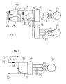
- Embodiments of the invention will be described with reference to the attached drawing. The figures of the drawing show:
- Fig. 1
- a cross sectional view of a rotor having a set of permanent magnets for generating the magnetic flux of the rotor,
- Fig. 2
- an arrangement for providing traction energy of a vehicle, wherein electric energy is provided by an AC power supply network,
- Fig. 3
- an arrangement for providing traction energy of a vehicle, wherein electric energy is provided by an AC power supply network.
-
Figure 1 shows a cross-section through a rotor 1 of a permanent magnet synchronous motor (PMSM). The axis of rotation is denoted by 6. The rotor comprises a plurality of circular discs made of steel which are stacked in order to form the rotor.Figure 1 shows one of the discs. The discs are fixed to a cylindrical shaft 7. Both the shaft 7 and the discs are coaxial to the axis of rotation 6. - Several slots S are cut out of the interior of the discs. Only some of the slots S are denoted by " S " and " S' " in
figure 1 . Each of the slots S, S' extends in a longitudinal direction which is parallel to the axis of rotation 6, i.e. extends perpendicularly to the image plane offigure 1 . Each of the slots is filled with apermanent magnet - In the image plane of
figure 1 (and in all parallel planes of the rotor 1), which plane extends perpendicularly to the axis of rotation 6, the slots S extend lengthwise in a direction which is inclined with reference to the radial direction. One radius line is denoted by "R" infigure 1 . The inclination angle is denoted by "φ". In the embodiment shown, all slots S are inclined by the same inclination angle and all slots S' are inclined by an inclination angle having the same amount, but is oriented in the opposite direction, i.e. the inclination angle is "-φ". For each slot S there is a corresponding slot S', wherein the inclination angle of slot S is given by φ and wherein the inclination angle of the corresponding slot S' is given by -φ. Furthermore the corresponding slots S, S' are located at the same distance to the axis of rotation 6, so that a radius line R can be defined for each pair of corresponding slots and the slots are located and oriented symmetrically to this radius line R. - Furthermore, there are two pairs of corresponding slots S, S' in each region around the rotor 1. One of the corresponding pairs has a greater length (filled with magnet 3) and one pair has a smaller length (filled with magnet 2). Both pairs are symmetric to the same radius line R. Consequently, the two pairs of corresponding slots form a double V, wherein the smaller V is located at least partly inside the opening of the larger V and the acute ends of the Vs are pointing to the axis of rotation 6. In circumference direction, these double Vs have two neighbour double Vs, but the magnetic fields of the magnets in the slots of the neighbours are oriented in the opposite direction (as indicated by arrows in
figure 1 ). In total there eight double Vs, so that the pole number of the rotor 1 is eight. - The slots are placed so that the magnet flux is concentrated and the flux-density in the airgap between the rotor and the stator can be higher than the flux-density in the magnets. Furthermore, the slots are placed so that the rotor will be salient, i.e. the synchronous inductance in the q-direction (the direction from the north pole to the south pole of the whole rotor) is higher than in the d-direction (the direction in between the poles of the rotor).
- At the acute end of the V (for example as indicated by "4"), only a comparatively small "bridge" made of the disc material separates the slots S, S'. The dimension of the bridge, i.e. the distance between the slots S, S' is a factor which influences the maximum allowed speed of the rotor. In particular, the bridge must withstand the centrifugal forces acting on the magnets and the rotor poles. If the rotor rotates at a higher speed, the material at the bridges might break and the rotor might be damaged.
- The bridges also have the function that the material at the bridges will saturate and thus limit the leakage of magnet flux.
- There are further slots 5 (in the example eight slots, corresponding to the pole number) extending perpendicularly to the image plane of
figure 1 through the whole rotor 1 and theseslots 5 are not filled with permanent magnets. During rotation of the rotor 1, air can flow through theslots 5 and the interior of the rotor is thereby cooled. -
Figure 2 shows an arrangement comprising twoPMSM 11. Each of themotors 11 is connected to atraction converter 13 via a three-phase AC connection 15. There is aswitch 14 in each of the lines of the three-phase AC connections 15. - The DC-side of the
traction converters 13 is connected toDC lines overvoltage protection device 18, acapacitor bank 19 and afilter branch 20 for filtering harmonic frequencies are connected between the DC lines 16, 17. - The DC lines 16, 17 are also connected to
line converters line converters transformer 25 and thetransformer 25 is connected to the AC line (not shown in detail). -
Figure 3 shows an arrangement comprising onePMSM 31. Themotor 31 is connected to atraction converter 33 via a three-phase AC connection 35. There is aswitch 34 in each of the lines of the three-phase AC connections 35. - The DC-side of the
traction converter 33 is connected toDC lines capacitor bank 42 is connected between the DC lines 36, 37 and a filter inductance 38 (DC choke) is provided inline 37. Thisline 37 is connected to a DCpower supply network 39, for example via apantograph 40.
Claims (13)
- An arrangement for generating a traction force of a track bound vehicle, in particular of a rail vehicle, the arrangement comprising:• a traction converter (13) adapted to convert a direct current (DC) to an alternating current (AC), the traction converter (13) having a first interface for connecting the traction converter (13) to a power source on a direct current side and having a second interface for connecting the traction converter (13) to at least one traction motor (11) on an alternating current side,• a traction motor (11) which is connected to the second interface,wherein a rotor (1) of the traction motor (11) is designed to generate the magnetic flux required to operate the motor (11) using permanent magnets (2, 3) and wherein the permanent magnets (2, 3) are mounted in the interior of the rotor (1).
- The arrangement of the preceding claim, wherein the arrangement comprises:• a traction transformer (25) having a primary winding and a secondary winding,• a line converter (21, 22) consisting of one or several pulsed converters adapted to convert an alternating current in a power supply line to a direct current, wherein the line converter (21, 22) is connected to the secondary winding of the traction transformer (25),• a capacitor battery (19) connected to the DC terminals of the pulsed inverter/inverters,wherein the traction converter (13) is consisting of one or several pulsed converters and the first interface being connected to the capacitor battery (19).
- The arrangement of claim 1, wherein the arrangement comprises a DC choke (38) having a first terminal connected to a DC power source (39) and a second terminal connected to a capacitor battery (42) connected electrically in parallel with the DC terminals of the traction converter (33).
- The arrangement of one of the two preceding claim, further comprising a series-resonant circuit (20) electrically connected in parallel with the capacitor battery (19).
- The arrangement of one of the three preceding claims, further comprising an overvoltage protection device (18) electrically connected in parallel with the capacitor battery (19).
- The arrangement of one of the preceding claims, the arrangement comprising electrical power connections (15) connecting the traction motor (11) with the second interface, wherein one or several of the electrical power connections (15) between the traction converter (13) and the traction motor (11) comprise an electrical switch (14), which can be actuated in order to interrupt the power connection (15).
- The arrangement of one of the preceding claims, wherein the traction motor (11) is connected to a gearbox for transferring mechanical energy for producing traction of the vehicle.
- The arrangement of one of the preceding claims, wherein the motor (11) is combined with a fan for producing an airflow for cooling the motor (11) and wherein the fan is mounted on a rotating shaft of the motor.
- The arrangement of one of the preceding claims, wherein the motor (11) is combined with a fan for producing an airflow for cooling the motor (11) and wherein the fan is a fan external to the motor (11).
- The arrangement of one of the preceding claims, wherein the motor (11) is combined with a cooling system adapted to cool the motor (11) using a cooling liquid.
- The arrangement of the preceding claim, wherein the cooling liquid is water.
- The arrangement of one of the preceding claims, wherein the average temperature of windings of at least one electromagnet of the stator of the motor is allowed to exceed 220°C.
- The arrangement of one of the preceding claims, wherein the average temperature of windings of at least one electromagnet of the stator of the motor is allowed to exceed 200°C.
Priority Applications (1)
| Application Number | Priority Date | Filing Date | Title |
|---|---|---|---|
| EP08014130A EP2151347A1 (en) | 2008-08-07 | 2008-08-07 | Arrangement for generating a traction force of a track bound vehicle |
Applications Claiming Priority (1)
| Application Number | Priority Date | Filing Date | Title |
|---|---|---|---|
| EP08014130A EP2151347A1 (en) | 2008-08-07 | 2008-08-07 | Arrangement for generating a traction force of a track bound vehicle |
Publications (1)
| Publication Number | Publication Date |
|---|---|
| EP2151347A1 true EP2151347A1 (en) | 2010-02-10 |
Family
ID=40042638
Family Applications (1)
| Application Number | Title | Priority Date | Filing Date |
|---|---|---|---|
| EP08014130A Withdrawn EP2151347A1 (en) | 2008-08-07 | 2008-08-07 | Arrangement for generating a traction force of a track bound vehicle |
Country Status (1)
| Country | Link |
|---|---|
| EP (1) | EP2151347A1 (en) |
Cited By (3)
| Publication number | Priority date | Publication date | Assignee | Title |
|---|---|---|---|---|
| JP2015056936A (en) * | 2013-09-11 | 2015-03-23 | 三菱電機株式会社 | Rotating electrical machine and cooling method for rotating electrical machine |
| JP2018039316A (en) * | 2016-09-06 | 2018-03-15 | 株式会社日立製作所 | COOLING DEVICE, Trolley equipped with the cooling device, and railway vehicle |
| EP3985863A4 (en) * | 2019-06-14 | 2023-07-05 | Hitachi, Ltd. | DRIVING DEVICE FOR THREE-PHASE AC MOTORS, RAILWAY VEHICLE EQUIPPED THEREOF, AND DRIVING METHOD FOR THREE-PHASE AC MOTORS |
Citations (4)
| Publication number | Priority date | Publication date | Assignee | Title |
|---|---|---|---|---|
| EP0993107A2 (en) * | 1998-10-05 | 2000-04-12 | ABB Daimler-Benz Transportation (Technology) GmbH | Power converter circuit |
| WO2005077703A1 (en) * | 2004-02-16 | 2005-08-25 | Siemens Aktiengesellschaft | Electric drive system |
| JP2006311692A (en) * | 2005-04-27 | 2006-11-09 | Toshiba Corp | Railway vehicle drive control device |
| US20070096578A1 (en) * | 2005-10-31 | 2007-05-03 | Jahns Thomas M | Device having permanent-magnet pieces |
-
2008
- 2008-08-07 EP EP08014130A patent/EP2151347A1/en not_active Withdrawn
Patent Citations (4)
| Publication number | Priority date | Publication date | Assignee | Title |
|---|---|---|---|---|
| EP0993107A2 (en) * | 1998-10-05 | 2000-04-12 | ABB Daimler-Benz Transportation (Technology) GmbH | Power converter circuit |
| WO2005077703A1 (en) * | 2004-02-16 | 2005-08-25 | Siemens Aktiengesellschaft | Electric drive system |
| JP2006311692A (en) * | 2005-04-27 | 2006-11-09 | Toshiba Corp | Railway vehicle drive control device |
| US20070096578A1 (en) * | 2005-10-31 | 2007-05-03 | Jahns Thomas M | Device having permanent-magnet pieces |
Cited By (3)
| Publication number | Priority date | Publication date | Assignee | Title |
|---|---|---|---|---|
| JP2015056936A (en) * | 2013-09-11 | 2015-03-23 | 三菱電機株式会社 | Rotating electrical machine and cooling method for rotating electrical machine |
| JP2018039316A (en) * | 2016-09-06 | 2018-03-15 | 株式会社日立製作所 | COOLING DEVICE, Trolley equipped with the cooling device, and railway vehicle |
| EP3985863A4 (en) * | 2019-06-14 | 2023-07-05 | Hitachi, Ltd. | DRIVING DEVICE FOR THREE-PHASE AC MOTORS, RAILWAY VEHICLE EQUIPPED THEREOF, AND DRIVING METHOD FOR THREE-PHASE AC MOTORS |
Similar Documents
| Publication | Publication Date | Title |
|---|---|---|
| US20210367484A1 (en) | High acceleration rotary actuator | |
| CN109327088B (en) | Rotary electric machine and electric vehicle equipped with the same | |
| JP5681026B2 (en) | Stator and rotating electric machine | |
| CN103201930B (en) | Vehicle-mounted dynamo-electric machine system | |
| CN111512519A (en) | Rotary motor | |
| CN103858318A (en) | Permanent magnet type rotating electrical machine and vehicle equipped with permanent magnet type rotating electrical machine | |
| EP4407844B1 (en) | Flat wire electric motor and stator thereof | |
| US20150311759A1 (en) | Asynchronous machine with optimized distribution of electrical losses between stator and rotor | |
| WO2018159181A1 (en) | Rotating electric machine rotor and rotating electric machine equipped with same | |
| JP2020512806A (en) | Rotating electric machine with optimized configuration | |
| US12136859B2 (en) | Electric machine | |
| CN107508440B (en) | An axial multi-unit stator electric excitation bipolar induction motor | |
| CN102403860B (en) | Equal pole double-section reluctance generator | |
| Feng et al. | Design and comparison of surface inset permanent magnet machine and surface permanent magnet machine without heavy rare earth magnets for traction applications | |
| EP2256907A1 (en) | An electric machine | |
| CN210780255U (en) | A high-speed vernier motor with conductor independent drive and compact structure | |
| CN112072883A (en) | Motor for oil pumping unit | |
| CN110635639A (en) | Radial magnetic field compound dual power flow motor | |
| CN115765370B (en) | Four-phase double-stator doubly salient motor | |
| KR20200099716A (en) | Apparatus for Multi-stage disk-type power generation | |
| CN108199551A (en) | A kind of non-overlapping winding tooth socket type birotor electric excitation synchronous motor | |
| CN209994255U (en) | Permanent magnet high-efficiency synchronous motor for ventilation system | |
| JP4984544B2 (en) | Power system | |
| Zhou et al. | Research on a four-phase fault-tolerant PMSM used for EVs | |
| JP2024098633A (en) | Rotary electric machine |
Legal Events
| Date | Code | Title | Description |
|---|---|---|---|
| PUAI | Public reference made under article 153(3) epc to a published international application that has entered the european phase |
Free format text: ORIGINAL CODE: 0009012 |
|
| AK | Designated contracting states |
Kind code of ref document: A1 Designated state(s): AT BE BG CH CY CZ DE DK EE ES FI FR GB GR HR HU IE IS IT LI LT LU LV MC MT NL NO PL PT RO SE SI SK TR |
|
| AX | Request for extension of the european patent |
Extension state: AL BA MK RS |
|
| 17P | Request for examination filed |
Effective date: 20100810 |
|
| AKX | Designation fees paid |
Designated state(s): AT BE BG CH CY CZ DE DK EE ES FI FR GB GR HR HU IE IS IT LI LT LU LV MC MT NL NO PL PT RO SE SI SK TR |
|
| 17Q | First examination report despatched |
Effective date: 20110120 |
|
| STAA | Information on the status of an ep patent application or granted ep patent |
Free format text: STATUS: THE APPLICATION IS DEEMED TO BE WITHDRAWN |
|
| 18D | Application deemed to be withdrawn |
Effective date: 20110603 |