EP2151294A1 - Linear compensator tool for drill countersinking and seal groove machining - Google Patents
Linear compensator tool for drill countersinking and seal groove machining Download PDFInfo
- Publication number
- EP2151294A1 EP2151294A1 EP09166998A EP09166998A EP2151294A1 EP 2151294 A1 EP2151294 A1 EP 2151294A1 EP 09166998 A EP09166998 A EP 09166998A EP 09166998 A EP09166998 A EP 09166998A EP 2151294 A1 EP2151294 A1 EP 2151294A1
- Authority
- EP
- European Patent Office
- Prior art keywords
- tool
- compensator
- nose piece
- outer casing
- casing
- Prior art date
- Legal status (The legal status is an assumption and is not a legal conclusion. Google has not performed a legal analysis and makes no representation as to the accuracy of the status listed.)
- Granted
Links
Images



Classifications
-
- B—PERFORMING OPERATIONS; TRANSPORTING
- B23—MACHINE TOOLS; METAL-WORKING NOT OTHERWISE PROVIDED FOR
- B23B—TURNING; BORING
- B23B31/00—Chucks; Expansion mandrels; Adaptations thereof for remote control
- B23B31/02—Chucks
- B23B31/08—Chucks holding tools yieldably
- B23B31/083—Chucks holding tools yieldably axially
-
- B—PERFORMING OPERATIONS; TRANSPORTING
- B23—MACHINE TOOLS; METAL-WORKING NOT OTHERWISE PROVIDED FOR
- B23B—TURNING; BORING
- B23B49/00—Measuring or gauging equipment on boring machines for positioning or guiding the drill; Devices for indicating failure of drills during boring; Centering devices for holes to be bored
- B23B49/003—Stops attached to drilling tools, tool holders or drilling machines
- B23B49/005—Attached to the drill
-
- B—PERFORMING OPERATIONS; TRANSPORTING
- B23—MACHINE TOOLS; METAL-WORKING NOT OTHERWISE PROVIDED FOR
- B23B—TURNING; BORING
- B23B51/00—Tools for drilling machines
- B23B51/10—Bits for countersinking
- B23B51/104—Bits for countersinking with stops
-
- B—PERFORMING OPERATIONS; TRANSPORTING
- B23—MACHINE TOOLS; METAL-WORKING NOT OTHERWISE PROVIDED FOR
- B23C—MILLING
- B23C3/00—Milling particular work; Special milling operations; Machines therefor
- B23C3/28—Grooving workpieces
-
- Y—GENERAL TAGGING OF NEW TECHNOLOGICAL DEVELOPMENTS; GENERAL TAGGING OF CROSS-SECTIONAL TECHNOLOGIES SPANNING OVER SEVERAL SECTIONS OF THE IPC; TECHNICAL SUBJECTS COVERED BY FORMER USPC CROSS-REFERENCE ART COLLECTIONS [XRACs] AND DIGESTS
- Y10—TECHNICAL SUBJECTS COVERED BY FORMER USPC
- Y10T—TECHNICAL SUBJECTS COVERED BY FORMER US CLASSIFICATION
- Y10T408/00—Cutting by use of rotating axially moving tool
- Y10T408/03—Processes
-
- Y—GENERAL TAGGING OF NEW TECHNOLOGICAL DEVELOPMENTS; GENERAL TAGGING OF CROSS-SECTIONAL TECHNOLOGIES SPANNING OVER SEVERAL SECTIONS OF THE IPC; TECHNICAL SUBJECTS COVERED BY FORMER USPC CROSS-REFERENCE ART COLLECTIONS [XRACs] AND DIGESTS
- Y10—TECHNICAL SUBJECTS COVERED BY FORMER USPC
- Y10T—TECHNICAL SUBJECTS COVERED BY FORMER US CLASSIFICATION
- Y10T408/00—Cutting by use of rotating axially moving tool
- Y10T408/55—Cutting by use of rotating axially moving tool with work-engaging structure other than Tool or tool-support
- Y10T408/561—Having tool-opposing, work-engaging surface
- Y10T408/5623—Having tool-opposing, work-engaging surface with presser foot
- Y10T408/56245—Having tool-opposing, work-engaging surface with presser foot including tool-guide [or bushing]
-
- Y—GENERAL TAGGING OF NEW TECHNOLOGICAL DEVELOPMENTS; GENERAL TAGGING OF CROSS-SECTIONAL TECHNOLOGIES SPANNING OVER SEVERAL SECTIONS OF THE IPC; TECHNICAL SUBJECTS COVERED BY FORMER USPC CROSS-REFERENCE ART COLLECTIONS [XRACs] AND DIGESTS
- Y10—TECHNICAL SUBJECTS COVERED BY FORMER USPC
- Y10T—TECHNICAL SUBJECTS COVERED BY FORMER US CLASSIFICATION
- Y10T408/00—Cutting by use of rotating axially moving tool
- Y10T408/55—Cutting by use of rotating axially moving tool with work-engaging structure other than Tool or tool-support
- Y10T408/564—Movable relative to Tool along tool-axis
- Y10T408/5653—Movable relative to Tool along tool-axis with means to bias Tool away from work
-
- Y—GENERAL TAGGING OF NEW TECHNOLOGICAL DEVELOPMENTS; GENERAL TAGGING OF CROSS-SECTIONAL TECHNOLOGIES SPANNING OVER SEVERAL SECTIONS OF THE IPC; TECHNICAL SUBJECTS COVERED BY FORMER USPC CROSS-REFERENCE ART COLLECTIONS [XRACs] AND DIGESTS
- Y10—TECHNICAL SUBJECTS COVERED BY FORMER USPC
- Y10T—TECHNICAL SUBJECTS COVERED BY FORMER US CLASSIFICATION
- Y10T408/00—Cutting by use of rotating axially moving tool
- Y10T408/83—Tool-support with means to move Tool relative to tool-support
- Y10T408/85—Tool-support with means to move Tool relative to tool-support to move radially
- Y10T408/858—Moving means including wedge, screw or cam
- Y10T408/8595—Pivotable tool-support
-
- Y—GENERAL TAGGING OF NEW TECHNOLOGICAL DEVELOPMENTS; GENERAL TAGGING OF CROSS-SECTIONAL TECHNOLOGIES SPANNING OVER SEVERAL SECTIONS OF THE IPC; TECHNICAL SUBJECTS COVERED BY FORMER USPC CROSS-REFERENCE ART COLLECTIONS [XRACs] AND DIGESTS
- Y10—TECHNICAL SUBJECTS COVERED BY FORMER USPC
- Y10T—TECHNICAL SUBJECTS COVERED BY FORMER US CLASSIFICATION
- Y10T408/00—Cutting by use of rotating axially moving tool
- Y10T408/89—Tool or Tool with support
- Y10T408/892—Tool or Tool with support with work-engaging structure detachable from cutting edge
- Y10T408/8925—Depth-limiting member
Definitions
- This invention relates in general to machining applications, and in particular to a linear compensator tool for drill countersinking and seal groove machining.
- the linear compensator tool ensures accurate drill countersinking and seal groove machining capabilities without control system feedback.
- NC Numerically Controlled
- NC machines required to perform these types of processes are forced to integrate a complicated, expensive, and time consuming process of measuring and recording surface profile variations prior to actual machining and drilling. These recorded part surface variations are then used to adjust, or offset, the NC program to account for the deviations from the engineered nominal surface.
- NC Machines outfitted with the capability to perform these types of processes are substantially more expensive and complicated due to the added components and control hardware and software to operate the system.
- the lack of viable low-cost drill countersinking tools forces companies to convert these machines into accurate drill countersinking machines with expensive modifications and/or total machine replacement. This situation is prevalent throughout the aircraft industry, both in the commercial and military sectors.
- the capability of sensing this surface location is incorporated into the machine and control system. This allows the machine to countersink to a depth relative to the sensed part surface.
- the drill countersink tool is fed a specific distance into the part relative to that surface to achieve the desired countersink diameter/depth.
- Retrofitting existing machines without the specific designed-in countersinking and seal groove machining capabilities is very expensive and results in substantial machine downtime during retrofit.
- Most NC Machines have no or limited available control lines to the spindle for intelligent drilling system. Integration costs for intelligent drilling systems are extremely costly and impact machine operations during installation/debugging.
- the drill countersinking and seal groove machining tool proposed in this patent application precludes having to implement substantial changes to the machine and/or additional processes to accommodate an accurate drill countersinking or seal groove machining operation.
- the functionality of the linear compensator tool allows it to be used like any other standard tool which does not require any interface to the control system or special NC Programming allowances.
- This tool can be setup and adjusted off-line of the machine, unlike many of the specially designed drill countersinking machines.
- This tool can be stored as a standard tool in the machine's automated tool storage/retrieval system.
- This tool effectively turns an ordinary NC milling machine into an automated drilling machine at a much lower cost and allows the use of existing machines without upgrading or replacing the equipment.
- This tool effectively turns an ordinary NC milling machine into an accurate seal groove milling machine without the need for elaborate measurements of the part surface profiles.
- the seal groove machining and drill countersinking tool incorporate a linear compensator design which applies sufficient force to react to the drilling or seal groove machining process, but not so much force as to distort the work piece being drilled or machined. Additionally, the linear compensator design ensures that the reactant force does not exceed the machine force override allowances. Varying spring rates and/or air pressures on the linear compensator system will accommodate most applications.
- the tool is designed to absorb over travel of the machining tool, in order to ensure that the surface to be machined is always in contact with the tool, Incorporation of the linear compensator system provides countersinking and seal groove machining capabilities that do not require some form of control system feedback.
- the linear compensator design can be adapted to virtually any numerical control machine spindle interface (i.e., HSK Holders, CAT Tapered Holders, etc.) with very minor modifications to the machine.
- a variety of adjustable micro-stop countersinking and seal groove machining assemblies can be adapted to the linear compensator system, enabling reaction to part surface profile variations and producing an accurate countersink or seal groove real time.
- standard tool holder 21 has a shaft 25 with a splined receptacle capable of receiving and rotating a tool.
- the tool is a countersinking drill bit 24.
- Tool holder 21 may hold one of a number of machining tools, including a seal groove cutter.
- a linear compensator tool is connected to a standard tool holder 21 to ensure accuracy in machining processes.
- the standard tool holder 21 is connected to a spindle of an NC machine 19.
- the LCT can exist in a number of embodiment including a linear bearing with springs LCT 121 ( Figures 8 and 9 ), and a mechanical sleeve with spring LCT 141 ( Figures 10 and 11 ).
- the LCT is a hollow shaft air cylinder LCT 31.
- LCT 31 is connected to tool holder 21 by means of a clocking ring 51 and a bearing (not visible).
- the bearing (not visible) is connected to clocking ring 51 by means of connector snap 55.
- the bearing (not visible) and clocking ring 51 are connected to tool holder 21 by means of connector snap 53.
- Locking pin 57 extends vertically from the top surface of ring 51, and slides into a bushing (not visible) on the face of NC machine 19. Clocking ring 51, the bearing (not visible), and locking pin 57 ensure that the body of LCT 31 is fixed and does not rotate with tool holder 21 and countersinking drill bit 24.
- casing 33 is generally cylindrical in shape with the exterior portion of casing 33 being smooth. In an alternate embodiment, casing 33 could take other forms such as a square or rectangle.
- the interior surface of casing 33 is machined in a manner to enable it to receive inner casing 37.
- the upper interior surface of casing 33 forms a downward facing shoulder 34.
- Inner casing 37 slidingly engages outer casing 33.
- casing 37 could take other forms such as a square or rectangle.
- the outer surface of casing 37 forms a flange section 38.
- Flange section 38 and shoulder 34 limit the movement of casing 37 within casing 33.
- O-ring seals 39, 41 ensure that the contact surfaces between outer casing 33 and inner casing 37 are properly sealed.
- a cap 35 is placed around inner casing 37, on the bottom of LCT 3 1, and is secured to outer casing 33.
- Cap 35 is generally circular in shape and has a T-shaped cross section that produces a small annulus between inner casing 37 and cap 35.
- O-ring seal 43 ensures that the contacting surfaces between inner casing 37 and cap 35 are sealed.
- Inner casing 37 is free to telescope in and out of casing 33, but is limited in range by cap 35 and shoulder 34.
- a spring 45 surrounds inner casing 37, and is located in the annulus between inner casing 37 and cap 35. Spring 45 acts to compress inner casing 37 as far as possible towards clocking ring 51.
- Air ports 47, 49 are located in outer casing 33. Port 47 is connected to a compressed air line, whereas port 49 is open to the atmosphere.
- Micro-stop nose piece 61 is attached to the bottom of inner casing 37 by way of mounting flange 77. As illustrated by Figures 3 and 4 , micro-stop nose piece 61 is comprised of various components. These components include nose piece 63, locking collar 65, locking ring 67, threaded fixture 69, shaft 79, and tool casing 85. Locking ring 67 is threaded, and is screwed on to threads 71 on fixture 69. Locking collar 65 slides onto fixture 69, and is positioned around threads 71. A pin (not visible) is located on the inner surface of collar 65, and slides into slot 75 on fixture 69. The pin (not visible), captured in slot 75, ensures that collar 65 can not rotate around fixture 69.
- One end of collar 65 is saw tooth patterned.
- Nose piece 63 is threaded on one end 63b, and is screwed onto the threads 73 on fixture 69.
- End 63b of nose piece 63 has teeth that align with the teeth on collar 65, preventing rotation of nose piece 63.
- End 63a of nose piece 63 has an aperture that extends from the main body of the nose piece 63, and allows a machining tool to pass through the aperture, forming a shoulder.
- shaft 79 One end of shaft 79 is splined, and the other extends through fixture 69, where tool collar 85 surrounds it. Just above collar 85, a thrust bearing 83 is placed on shaft 79. Pinned collar 81, located just above bearing 83, holds bearing 83 in place on shaft 79.
- the shaft assembly is inserted into nose piece fixture 69.
- Section 87 of the nose piece assembly 61 contains a close tolerance pilot that controls the center line of shaft 79.
- a locking ring 89 which locks the pilot in place.
- the locking ring 89 is another locking ring 91 which locks shaft 79 into the micro-stop nose piece assembly 61.
- hollow shaft air cylinder LCT 31 is connected to a standard tool holder 21 for countersinking.
- Standard tool holder 21 is connected to a spindle of NC machine 19.
- LCT 31 is connected to tool holder 21 as previously discussed.
- a countersinking drill bit 24 is inserted into the micro stop nose piece assembly 61.
- Bit 24 has a counterbore portion 24a at its upper end that extends below end 63a of nose piece 63.
- nose piece 63 is adjusted to ensure the desired countersink depth. The desired depth is determined by the extent that bit 24, and in particular counterbore portion 24a extends below the aperture on end 63a of nose piece 63.
- Nose piece 63 is adjusted by screwing ring 67 toward connector flange 77. Locking collar 65 is then free to move up or down on fixture 69.
- Nose piece 63 is then rotated on threads 73 in order to control the extent that counterbore portion 24a of bit 24 extends below end 63a.
- locking collar 65 is positioned to lockingly engage the teeth on end 63b of nose piece 63.
- Locking ring 67 is then tightened securely against collar 65, locking the nose piece 63 in position and ensuring the desired drill depth of bit 24.
- NC machine 19 is programmed to lower tool holder 21 from a starting point 106 to a point 107 based on the thickness of the minimum thickness panel 105. Programming will ensure that counterbore portion 24a of bit 24 cuts to the proper depth of the panel regardless of wether the panel is one of maximum thickness 101, nominal thickness 103, or minimum thickness 105, Typical variations in panel thickness are illustrated by 109, and in one embodiment, may be less than 0.020 inches.
- the programmed point 107 is the same point in space regardless of the thickness of panels 101, 103, 105.
- Programmed point 107 is determined by measuring the amount of travel it takes for end 24a to form the counterbore in minimum thickness panel 105 to the correct depth.
- the travel of tool holder 21 to point 107 should equal the distance d in Figure 5C .
- the traveled distance of tool holder 21 to point 107 will be slightly greater than the distance d'; which is the distance counterbore end 24a travels to cut the counterbore to the proper depth in medium thickness panel 103 ( Figure 5B ).
- the traveled distance of LCT 31 to point 107 will be even greater than the distance d", which is the distance counterbore end 24a travels to cut the counterbore to the proper depth in maximum thickness panel 10 ( Figure 5A ).
- pressure is supplied to LCT 31 by an air source (not shown), which pumps air into LCT 31.
- Air enters LCT 31 through port 47 and fills the annulus between outer casing 33 and inner casing 37.
- inner casing 37 fully extends outwards from casing 33.
- port 49 ensures that any air trapped below flange 38 in the annulus between casing 37 and casing 33 is vented to the atmosphere.
- a gap 112 exists between shoulder 34 and flange 38. Gap 112 is designed to absorb over travel of tool holder 21, and in one embodiment, gap 112 is designed to absorb up to 0.100 inches of over travel.
- the tool holder 21 starts at the same elevation 106 and ends at the same elevation 107.
- NC machine 19 rotates countersinking drill bit 24 and begins lowering tool holder 21 and bit 24 toward programmed point 107.
- tool holder 21 is at a different distance from the panel depending on the panel thickness.
- bit 24 starts drilling sooner than with panel 105 because it contacts panel 103 at a lesser distance d'.
- the pressure of LCT 31 is such that bit 24 will penetrate the panel surface and continue toward the desired point 107 without any change in the position of flange 38, as illustrated by Figure 6B .
- nose piece 63a contacts panel 103, tool holder 21 is not yet at point 107.
- the resistance of nosepiece 63a overcomes the air pressure, causing shoulder 34 to advance toward flange 38.
- shaft 79 advances further into receptacle 25 ( Figure 2 ). Drill bit 24 does not move further downward, however, as it has fully cut the counterbore and nosepiece 63a prevents further downward movement.
- bit 24 starts drilling sooner than with panels 105, 103 because it contacts panel 101 at a lesser distance d".
- the pressure of LCT 31 is such that bit 24 will penetrate the panel surface and continue toward the desired point 107 without any change in the position of flange 38, as illustrated by Figure 6A .
- Drill bit counterbore 24a will have cut to the full depth before LCT 31 has reached point 107.
- nosepiece 63a prevents further downward movement of drill bit portion 24a, causing shoulder 34 to advance toward flange 38.
- shaft 79 advances further into receptacle 25 ( Figure 2 ).
- LCT 31 continues downward until reaching point 107.
- the amount of over travel absorbed by LCT 31 varies with the panel thickness.
- Figure 7C when drilling a panel of minimum thickness 105, LCT 31 absorbs the least amount or no over travel. Due to the thickness of panel 105, the shoulder formed by the aperture on end 63b of nose piece 63 contacts the panel surface when tool holder 21 reaches point 107, which is programmed for the minimum thickness panel 105. In one example, there is no over travel to be absorbed. Accordingly, at the end of the machining operation, the original gap 112 between flange 38 and shoulder 34 remains.
- LCT 31 absorbs over travel. Due to the thickness of panel 103, the shoulder formed by the aperture on end 63b of nose piece 63 contacts the panel surface before tool holder 21 reaches point 107, which is programmed for the minimum thickness panel 105, As a result, LCT 31 must absorb the over travel distance 110, which is equal to the difference between d' and d ( Figures 5B and 5C ). In one example, shoulder 34 has advanced towards flange 38, leaving a gap 113.
- LCT 31 absorbs the greatest amount of over travel. Due to the thickness of panel 101, the shoulder formed by the aperture on end 63b of nose piece 63 contacts the panel surface before tool holder 21 reaches point 107, which is programmed for the minimum thickness panel 105, As a result, LCT 31 must absorb the over travel distance 111, which is equal to the difference between d" and d ( Figures 5A and 5C ). In one example, the over travel distance 111 is equal to original distance 112 that LCT 31 was designed to absorb. Accordingly, when tool holder 21 reaches point 107, flange 38 is in contact with shoulder 34.
- LCT 31 operates as previously discussed when connected to a standard tool holder 21 for seal groove machining.
- the gap between flange 38 and shoulder 34 allows LCT 31 to absorb over-travel by the tool holder, which guarantees nosepiece 63 contacts the panel surface resulting in a consistent seal groove width / depth regardless of the panel thickness.
- the variations in panel thickness illustrated above may be present over the surface profile of a single panel sought to be machined.
- LCT 31 responds to variations in the surface profile of a panel by compressing (absorbing over travel) or extending depending on the panel thickness at a given point.
- LCT is illustrated in the form of linear bearings with spring LCT 121.
- LCT 121 is connected to tool holder 21 by means of clocking ring 51 and a bearing (not visible).
- Bearing (not visible) is connected to clocking ring 51 by means of connector snap 55.
- Bearing (not visible) and clocking ring 51 are connected to tool holder 21 by means of connector snap 53.
- Locking pin 57 extends vertically from the top face of ring 51, and slides into a bushing (not visible) on the face of the NC machine. Clocking ring 51, bearing (not visible), and locking pin 57 ensure that the body of LCT 121 is fixed and does not rotate with tool holder 21 and drill countersinking bit 24.
- a plurality of flanged linear bearings 127 are attached to the bottom of clocking ring 51. Bearings 127 extend downward towards mounting plate 123.
- Mounting plate 123 is circular in shape, but in an alternate embodiment could take other forms such as a square or rectangle.
- a rod 129 travels through each linear bearing 127 and extends downward before connecting to mounting plate 123.
- Locking nuts 130 are attached to the end of rods 129 opposite mounting plate 123. Nuts 130 ensure that rods 129 are fixed between clocking ring 51 and mounting plate 123.
- Rods 129 can move axially in linear bearings 127, but are limited in range of movement due to nut 130 on one end and linear bearing 127 on the other.
- each rod 129 and linear bearing 127 Surrounding each rod 129 and linear bearing 127 is a spring 131, which is connected between clocking ring 51 and mounting plate 123.
- Spring 131 acts to ensure that LCT 121 is fully extended in its natural state, ensuring a maximum gap between clocking ring 51 and mounting plate 123.
- Plate 125 is connected to the bottom of mounting plate 123.
- Micro-stop nose piece 61 is attached to the bottom of plate 125 by way of mounting flange 77. Once micro-stop nose piece assembly 61 is mounted to plate 125, the splined end of shaft 79 is connected to tool holder shaft hub 25. Shaft 79 can move axially within LCT 121 due to the splined end and hub.
- Linear bearings with spring LCT 121 performs just as LCT 31.
- Figure 8 illustrates LCT 121 in a natural state, prior to contacting a workpiece. Gap 133 between linear bearings 127 and mounting plate 123 is the largest when plate 123 is fully extended.
- Figure 9 illustrates LCT 121 absorbing over travel, as indicated by the decreased size of gap 133.
- LCT 141 is illustrated in the form of spring actuated cylinder LCT 141.
- LCT 141 is connected to tool holder 21 by means of clocking ring 51 and a bearing (not visible).
- Bearing (not visible) is connected to clocking ring 51 by means of connector snap 55.
- Bearing (not visible) and clocking ring 51 are connected to tool holder 21 by means of connector snap 53.
- Locking pin 57 extends vertically from the top face of ring 51, and slides into a bushing (not visible) on the face of the NC machine. Clocking ring 51, bearing (not visible), and locking pin 57 ensure that the body of LCT 141 is fixed and does not rotate with tool holder 21 and drill countersinking bit 24.
- Mounting plate 143 is generally cylindrical and flat, with a T-shaped cross section 144 on each side.
- Outer casing 145 is machined to slide over and connect securely to mounting plate 143 of LCT 141.
- Casing 145 is generally cylindrical in shape with the exterior portion of casing 145 being smooth. In an alternate embodiment, casing 145 could take other forms such as a square or rectangle.
- the interior surface of casing 145 is machined in a manner to enable it to receive inner casing 147.
- the lower interior surface of casing 145 forms an upward facing shoulder 146.
- Inner casing 147 slidingly engages outer casing 145.
- casing 147 could take other forms such as a square or rectangle.
- the outer surface of casing 147 forms a flange section 148.
- Flange section 148 of casing 147, shoulder 146 of casing 145, and T-cross section 144 of plate 143 limit the movement of casing 147 within casing 145.
- Plate 143, outer casing 145, and inner casing 147 are machined to connect to one another with extremely close tolerances to form a mechanical sleeve.
- a small annulus if formed between the inner casing 147 and T-shaped cross section 144 of plate 143.
- Inner casing 147 is free to telescope in and out of casing 145, but is limited in range by section 144 of plate 143 and shoulder 146 of outer casing 145.
- a spring 149 surrounds inner casing 147, and is located in the annulus between inner casing 147 and outer casing 145.
- Spring 149 acts to ensure that LCT 141 is fully extended in its natural state, ensuing a maximum gap between flange 148 and T-section 144.
- Air ports 151 are located on the exterior of outer casing 145. Air ports 151 are open to the atmosphere and ensure that LCT 141 does not become pressurized with the telescoping movement of inner casing 147.
- Micro-stop nose piece 61 is attached to the bottom of inner casing 147 by way of mounting flange 77. Once micro-stop nose piece assembly 61 is mounted to casing 147, the splined end of shaft 79 is connected to the tool holder shaft hub 25. Shaft 79 can move axially within LCT 141 due to the splined end and hub.
- LCT 141 performs just as LCT 31 and LCT 121.
- Figure 10 illustrates LCT 141 in a natural state prior to contacting a workpiece. Gap 153, between flange 148 and T-section 144 is the largest when casing 147 is fully extended.
- Figure 11 illustrates LCT 141 absorbing over travel, as indicated by the decreased size of gap 153.
- linear compensator tool could be used in a number of various machining applications requiring material surface accuracy.
Landscapes
- Engineering & Computer Science (AREA)
- Mechanical Engineering (AREA)
- Drilling And Boring (AREA)
Abstract
Description
- This invention relates in general to machining applications, and in particular to a linear compensator tool for drill countersinking and seal groove machining. The linear compensator tool ensures accurate drill countersinking and seal groove machining capabilities without control system feedback.
- Current fabrication processes for trimming and drilling, and machining fuel seal grooves in composite and metallic aircraft panels utilize standard 3, 4, and 5 axis Numerically Controlled (NC) machine tools. Numerous machines of this type exist at aerospace companies which do not have integrated capabilities for machining operations to achieve specific seal groove widths/depths. Furthermore, these machines typically do not have integrated capabilities for performing drill countersinking operations to achieve specific countersink sizes/depths, and are relegated to drill-only operations which do not require specific depth control.
- NC machines required to perform these types of processes are forced to integrate a complicated, expensive, and time consuming process of measuring and recording surface profile variations prior to actual machining and drilling. These recorded part surface variations are then used to adjust, or offset, the NC program to account for the deviations from the engineered nominal surface. NC Machines outfitted with the capability to perform these types of processes are substantially more expensive and complicated due to the added components and control hardware and software to operate the system. The lack of viable low-cost drill countersinking tools forces companies to convert these machines into accurate drill countersinking machines with expensive modifications and/or total machine replacement. This situation is prevalent throughout the aircraft industry, both in the commercial and military sectors.
- Numerous machines exist today in production throughout the world without the capability to accurately machine seal grooves and drill countersink without substantial additional processes to accommodate the variations seen in composite and/or metallic panels, including surface profile variations. Numerically Controlled machines are programmed to move to a specific point in space without regard to where the actual part might be located. It is assumed that the part is located within a specific tolerance within the machine's work cell to achieve the desired level of accuracy during processing. Very small variations in machine accuracy and part location (i.e., as small as .001"- smaller than the thickness of a human hair) will result in seal groove widths and depths, and countersink diameters out of tolerance.
- The primary issues with accurate seal groove machining and drill countersinking of composite or metallic parts is knowing or being able to reference the part's surface profile that will be machine, or the part's surface that will be drilled. All seal grooves and countersinks are referenced by this surface. There is currently no Commercial-Off-The-Shelf (COTS) seal groove machining system available in industry which can accurately machine a seal groove to a specified width and depth while adjusting to varying part surface profiles real time without some type of control system feedback or extensive measurement operations to identify the actual part surface profile.
- In at expensive and complicated Automated Drilling Machine or Intelligent Drilling System the capability of sensing this surface location is incorporated into the machine and control system. This allows the machine to countersink to a depth relative to the sensed part surface. When the surface is located physically, or by non-contact methods, the drill countersink tool is fed a specific distance into the part relative to that surface to achieve the desired countersink diameter/depth.
- Retrofitting existing machines without the specific designed-in countersinking and seal groove machining capabilities is very expensive and results in substantial machine downtime during retrofit. Most NC Machines have no or limited available control lines to the spindle for intelligent drilling system. Integration costs for intelligent drilling systems are extremely costly and impact machine operations during installation/debugging.
- The drill countersinking and seal groove machining tool proposed in this patent application precludes having to implement substantial changes to the machine and/or additional processes to accommodate an accurate drill countersinking or seal groove machining operation. The functionality of the linear compensator tool allows it to be used like any other standard tool which does not require any interface to the control system or special NC Programming allowances. This tool can be setup and adjusted off-line of the machine, unlike many of the specially designed drill countersinking machines. This tool can be stored as a standard tool in the machine's automated tool storage/retrieval system.
- This tool effectively turns an ordinary NC milling machine into an automated drilling machine at a much lower cost and allows the use of existing machines without upgrading or replacing the equipment. This tool effectively turns an ordinary NC milling machine into an accurate seal groove milling machine without the need for elaborate measurements of the part surface profiles.
- The seal groove machining and drill countersinking tool incorporate a linear compensator design which applies sufficient force to react to the drilling or seal groove machining process, but not so much force as to distort the work piece being drilled or machined. Additionally, the linear compensator design ensures that the reactant force does not exceed the machine force override allowances. Varying spring rates and/or air pressures on the linear compensator system will accommodate most applications. The tool is designed to absorb over travel of the machining tool, in order to ensure that the surface to be machined is always in contact with the tool, Incorporation of the linear compensator system provides countersinking and seal groove machining capabilities that do not require some form of control system feedback.
- The linear compensator design can be adapted to virtually any numerical control machine spindle interface (i.e., HSK Holders, CAT Tapered Holders, etc.) with very minor modifications to the machine. A variety of adjustable micro-stop countersinking and seal groove machining assemblies can be adapted to the linear compensator system, enabling reaction to part surface profile variations and producing an accurate countersink or seal groove real time.
-
-
Figure 1 is a schematic side view of a standard tool holder connected to a NC machine. -
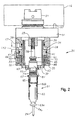
Figure 2 is a schematic sectional view of a hollow shaft air cylinder linear compensator tool attached to a standard tool holder and NC machine. -
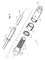
Figure 3 is a schematic side view of a micro-stop nose piece. -
Figure 4 is an exploded isometric view of the micro-stop nose piece ofFigure 3 . -
Figure 5A is a schematic sectional view of the linear compensator tool ofFigure 2 at the beginning of a machining operation of a maximum thickness panel. -
Figure 5B is a schematic sectional view of the linear compensator tool ofFigure 2 at the beginning of a machining operation of a nominal thickness panel. -
Figure 5C is a schematic sectional view of the linear compensator tool ofFigure 2 at the beginning of a machining operation of a minimum thickness panel. -
Figure 6A is a schematic sectional view of the linear compensator tool ofFigure 2 when first contacting the maximum thickness panel. -
Figure 6B is a schematic sectional view of the linear compensator tool ofFigure 2 when first contacting the nominal thickness panel. -
Figure 6C is a schematic sectional view of the linear compensator tool ofFigure 2 when first contacting the minimum thickness panel. -
Figure 7A is a schematic sectional view of the linear compensator tool ofFigure 2 after drill countersinking a maximum thickness panel. -
Figure 7B is a schematic sectional view of the linear compensator tool ofFigure 2 after drill countersinking a nominal thickness panel. -
Figure 7C is a schematic sectional view of the linear compensator tool ofFigure 2 after drill countersinking a minimum thickness panel. -
Figure 8 is a schematic sectional view of a linear bearings with springs linear compensator tool. -
Figure 9 is a schematic sectional view of the linear compensator tool ofFigure 8 after absorbing over travel. -
Figure 10 is a schematic sectional view of a mechanical sleeve with spring linear compensator tool. -
Figure 11 is a schematic sectional view of the linear compensator tool ofFigure 10 after absorbing over travel. - Referring to
Figure 1 ,standard tool holder 21 has ashaft 25 with a splined receptacle capable of receiving and rotating a tool. In this instance, the tool is acountersinking drill bit 24.Tool holder 21 may hold one of a number of machining tools, including a seal groove cutter. - Referring to
Figure 2 , a linear compensator tool (LCT) is connected to astandard tool holder 21 to ensure accuracy in machining processes. Thestandard tool holder 21 is connected to a spindle of anNC machine 19. The LCT can exist in a number of embodiment including a linear bearing with springs LCT 121 (Figures 8 and9 ), and a mechanical sleeve with spring LCT 141 (Figures 10 and11 ). In this example, the LCT is a hollow shaftair cylinder LCT 31. As illustrated byFigure 2 , LCT 31 is connected totool holder 21 by means of a clockingring 51 and a bearing (not visible). The bearing (not visible) is connected to clockingring 51 by means ofconnector snap 55. The bearing (not visible) andclocking ring 51 are connected totool holder 21 by means ofconnector snap 53. Lockingpin 57 extends vertically from the top surface ofring 51, and slides into a bushing (not visible) on the face ofNC machine 19. Clockingring 51, the bearing (not visible), and lockingpin 57 ensure that the body ofLCT 31 is fixed and does not rotate withtool holder 21 andcountersinking drill bit 24. - Attached to the bottom of clocking
ring 51 isouter casing 33 ofLCT 31.Casing 33 is generally cylindrical in shape with the exterior portion ofcasing 33 being smooth. In an alternate embodiment, casing 33 could take other forms such as a square or rectangle. The interior surface of casing 33 is machined in a manner to enable it to receiveinner casing 37. The upper interior surface of casing 33 forms a downward facingshoulder 34. -
Inner casing 37, generally cylindrical in shape, slidingly engagesouter casing 33. In an alternate embodiment, casing 37 could take other forms such as a square or rectangle. The outer surface of casing 37 forms aflange section 38.Flange section 38 andshoulder 34 limit the movement ofcasing 37 withincasing 33. O-ring seals outer casing 33 andinner casing 37 are properly sealed. Acap 35 is placed aroundinner casing 37, on the bottom of LCT 3 1, and is secured toouter casing 33.Cap 35 is generally circular in shape and has a T-shaped cross section that produces a small annulus betweeninner casing 37 andcap 35. O-ring seal 43 ensures that the contacting surfaces betweeninner casing 37 andcap 35 are sealed.Inner casing 37 is free to telescope in and out ofcasing 33, but is limited in range bycap 35 andshoulder 34. - A
spring 45 surroundsinner casing 37, and is located in the annulus betweeninner casing 37 andcap 35.Spring 45 acts to compressinner casing 37 as far as possible towards clockingring 51.Air ports outer casing 33.Port 47 is connected to a compressed air line, whereasport 49 is open to the atmosphere. -
Micro-stop nose piece 61 is attached to the bottom ofinner casing 37 by way of mountingflange 77. As illustrated byFigures 3 and4 ,micro-stop nose piece 61 is comprised of various components. These components includenose piece 63, lockingcollar 65, lockingring 67, threadedfixture 69,shaft 79, andtool casing 85. Lockingring 67 is threaded, and is screwed on tothreads 71 onfixture 69. Lockingcollar 65 slides ontofixture 69, and is positioned aroundthreads 71. A pin (not visible) is located on the inner surface ofcollar 65, and slides intoslot 75 onfixture 69. The pin (not visible), captured inslot 75, ensures thatcollar 65 can not rotate aroundfixture 69. One end ofcollar 65 is saw tooth patterned.Nose piece 63 is threaded on oneend 63b, and is screwed onto thethreads 73 onfixture 69.End 63b ofnose piece 63 has teeth that align with the teeth oncollar 65, preventing rotation ofnose piece 63.End 63a ofnose piece 63 has an aperture that extends from the main body of thenose piece 63, and allows a machining tool to pass through the aperture, forming a shoulder. - One end of
shaft 79 is splined, and the other extends throughfixture 69, wheretool collar 85 surrounds it. Just abovecollar 85, athrust bearing 83 is placed onshaft 79. Pinnedcollar 81, located just above bearing 83, holds bearing 83 in place onshaft 79. The shaft assembly is inserted intonose piece fixture 69.Section 87 of thenose piece assembly 61 contains a close tolerance pilot that controls the center line ofshaft 79. Just abovesection 87 is a lockingring 89 which locks the pilot in place. Just above the lockingring 89 is another lockingring 91 which locksshaft 79 into the micro-stopnose piece assembly 61. Once mounted toinner casing 37, the splined end ofshaft 79 is connected to the toolholder shaft hub 25.Shaft 79 can move axially withinLCT 31 due to the splined end and hub. - As illustrated by
Figures 5A, 5B, and 5C , hollow shaftair cylinder LCT 31 is connected to astandard tool holder 21 for countersinking.Standard tool holder 21 is connected to a spindle ofNC machine 19.LCT 31 is connected totool holder 21 as previously discussed. - A
countersinking drill bit 24 is inserted into the micro stopnose piece assembly 61.Bit 24 has acounterbore portion 24a at its upper end that extends belowend 63a ofnose piece 63. Referring back toFigures 3 and4 ,nose piece 63 is adjusted to ensure the desired countersink depth. The desired depth is determined by the extent that bit 24, and inparticular counterbore portion 24a extends below the aperture onend 63a ofnose piece 63.Nose piece 63 is adjusted by screwingring 67 towardconnector flange 77. Lockingcollar 65 is then free to move up or down onfixture 69.Nose piece 63 is then rotated onthreads 73 in order to control the extent thatcounterbore portion 24a ofbit 24 extends belowend 63a. Once the desired depth is set, lockingcollar 65 is positioned to lockingly engage the teeth onend 63b ofnose piece 63. Lockingring 67 is then tightened securely againstcollar 65, locking thenose piece 63 in position and ensuring the desired drill depth ofbit 24. -
NC machine 19 is programmed to lowertool holder 21 from astarting point 106 to apoint 107 based on the thickness of theminimum thickness panel 105. Programming will ensure thatcounterbore portion 24a ofbit 24 cuts to the proper depth of the panel regardless of wether the panel is one ofmaximum thickness 101,nominal thickness 103, orminimum thickness 105, Typical variations in panel thickness are illustrated by 109, and in one embodiment, may be less than 0.020 inches. - The programmed
point 107 is the same point in space regardless of the thickness ofpanels Programmed point 107 is determined by measuring the amount of travel it takes forend 24a to form the counterbore inminimum thickness panel 105 to the correct depth. The travel oftool holder 21 to point 107 should equal the distance d inFigure 5C . The traveled distance oftool holder 21 to point 107 will be slightly greater than the distance d'; which is thedistance counterbore end 24a travels to cut the counterbore to the proper depth in medium thickness panel 103 (Figure 5B ). The traveled distance ofLCT 31 to point 107 will be even greater than the distance d", which is thedistance counterbore end 24a travels to cut the counterbore to the proper depth in maximum thickness panel 10 (Figure 5A ). - Referring back to
Figure 2 , pressure is supplied toLCT 31 by an air source (not shown), which pumps air intoLCT 31. Air entersLCT 31 throughport 47 and fills the annulus betweenouter casing 33 andinner casing 37. AsLCT 31 is pressurized,inner casing 37 fully extends outwards from casing 33. Asinner casing 37 extends outwards from casing 33,port 49 ensures that any air trapped belowflange 38 in the annulus betweencasing 37 andcasing 33 is vented to the atmosphere. When casing 37 is fully extended, agap 112 exists betweenshoulder 34 andflange 38.Gap 112 is designed to absorb over travel oftool holder 21, and in one embodiment,gap 112 is designed to absorb up to 0.100 inches of over travel. The air pressure is sufficient so thatdrill bit 24 will not causeshoulder 34 to move towardflange 38 as it drills, However, when nose piece end 63a contacts the surface of one of thepanels Figures 7 ). - As illustrated by
Figures 5A, 5B, and 5C , thetool holder 21 starts at thesame elevation 106 and ends at thesame elevation 107.NC machine 19 rotates countersinkingdrill bit 24 and begins loweringtool holder 21 andbit 24 toward programmedpoint 107. Given the different thicknesses ofpanels tool holder 21 is at a different distance from the panel depending on the panel thickness. - Considering
minimum thickness panel 105, whenbit 24first contacts panel 105, the pressure ofLCT 31 is such thatbit 24 will penetrate the panel surface and continue toward the desiredpoint 107 without any change in the position offlange 38, as illustrated byFigure 6C . AsNC machine 19 continues to lowertool holder 21,bit 24 rotates and continues downwards until it has penetrated the panel and drillbit counterbore portion 24a has cut the proper counterbore depth inpanel 105. The pressure ofLCT 31 is regulate such that the once the shoulder onend 63a contacts the panel surface, the force acting upwards againstnose piece 63 is greater than the force acting downwards oninner casing 37. However, when machining theminimum thickness panel 105, end 63 a contacts the surface whentool holder 21 is atpoint 107, as illustrated byFigure 7C . TheNC machine 19 stops drilling oncetool holder 21 has reachedpoint 107. - Considering
nominal thickness panel 103, bit 24 starts drilling sooner than withpanel 105 because itcontacts panel 103 at a lesser distance d'. The pressure ofLCT 31 is such thatbit 24 will penetrate the panel surface and continue toward the desiredpoint 107 without any change in the position offlange 38, as illustrated byFigure 6B . Whennose piece 63a contacts panel 103,tool holder 21 is not yet atpoint 107. The resistance ofnosepiece 63a overcomes the air pressure, causingshoulder 34 to advance towardflange 38. Asshoulder 34 advances towardflange 38,shaft 79 advances further into receptacle 25 (Figure 2 ).Drill bit 24 does not move further downward, however, as it has fully cut the counterbore andnosepiece 63a prevents further downward movement. - For
maximum thickness panel 101, the same occurs as withnominal thickness panel 103.Bit 24 starts drilling sooner than withpanels contacts panel 101 at a lesser distance d". The pressure ofLCT 31 is such thatbit 24 will penetrate the panel surface and continue toward the desiredpoint 107 without any change in the position offlange 38, as illustrated byFigure 6A .Drill bit counterbore 24a will have cut to the full depth beforeLCT 31 has reachedpoint 107. AsLCT 31 moves further downward,nosepiece 63a prevents further downward movement ofdrill bit portion 24a, causingshoulder 34 to advance towardflange 38. Asshoulder 34 advances towardflange 38,shaft 79 advances further into receptacle 25 (Figure 2 ). - As illustrated by
Figures 7A, 7B, and 7C ,LCT 31 continues downward until reachingpoint 107. The amount of over travel absorbed byLCT 31 varies with the panel thickness. As illustrated byFigure 7C , when drilling a panel ofminimum thickness 105,LCT 31 absorbs the least amount or no over travel. Due to the thickness ofpanel 105, the shoulder formed by the aperture onend 63b ofnose piece 63 contacts the panel surface whentool holder 21 reaches point 107, which is programmed for theminimum thickness panel 105. In one example, there is no over travel to be absorbed. Accordingly, at the end of the machining operation, theoriginal gap 112 betweenflange 38 andshoulder 34 remains. - As illustrated by
Figure 7B , when drilling a panel ofnominal thickness 103,LCT 31 absorbs over travel. Due to the thickness ofpanel 103, the shoulder formed by the aperture onend 63b ofnose piece 63 contacts the panel surface beforetool holder 21 reaches point 107, which is programmed for theminimum thickness panel 105, As a result,LCT 31 must absorb the overtravel distance 110, which is equal to the difference between d' and d (Figures 5B and 5C ). In one example,shoulder 34 has advanced towardsflange 38, leaving a gap 113. - Referring to
Figure 7A , when drilling a panel ofmaximum thickness 101,LCT 31 absorbs the greatest amount of over travel. Due to the thickness ofpanel 101, the shoulder formed by the aperture onend 63b ofnose piece 63 contacts the panel surface beforetool holder 21 reaches point 107, which is programmed for theminimum thickness panel 105, As a result,LCT 31 must absorb the overtravel distance 111, which is equal to the difference between d" and d (Figures 5A and 5C ). In one example, the overtravel distance 111 is equal tooriginal distance 112 thatLCT 31 was designed to absorb. Accordingly, whentool holder 21 reaches point 107,flange 38 is in contact withshoulder 34. -
LCT 31 operates as previously discussed when connected to astandard tool holder 21 for seal groove machining. The only change in regard to the operation ofLCT 31 when seal groove machining is countersinkingdrill bit 24 is replaced with a seal groove cutting tool. As explained above, the gap betweenflange 38 andshoulder 34 allowsLCT 31 to absorb over-travel by the tool holder, which guaranteesnosepiece 63 contacts the panel surface resulting in a consistent seal groove width / depth regardless of the panel thickness. The variations in panel thickness illustrated above may be present over the surface profile of a single panel sought to be machined. During the seal groove machining process,LCT 31 responds to variations in the surface profile of a panel by compressing (absorbing over travel) or extending depending on the panel thickness at a given point. - Referring to
Figures 8 and9 , an alternate embodiment LCT is illustrated in the form of linear bearings withspring LCT 121.LCT 121 is connected totool holder 21 by means of clockingring 51 and a bearing (not visible). Bearing (not visible) is connected to clockingring 51 by means ofconnector snap 55. Bearing (not visible) andclocking ring 51 are connected totool holder 21 by means ofconnector snap 53. Lockingpin 57 extends vertically from the top face ofring 51, and slides into a bushing (not visible) on the face of the NC machine. Clockingring 51, bearing (not visible), and lockingpin 57 ensure that the body ofLCT 121 is fixed and does not rotate withtool holder 21 and drill countersinkingbit 24. - A plurality of flanged
linear bearings 127 are attached to the bottom of clockingring 51.Bearings 127 extend downward towards mountingplate 123. Mountingplate 123 is circular in shape, but in an alternate embodiment could take other forms such as a square or rectangle. Arod 129 travels through eachlinear bearing 127 and extends downward before connecting to mountingplate 123. Lockingnuts 130 are attached to the end ofrods 129 opposite mountingplate 123.Nuts 130 ensure thatrods 129 are fixed between clockingring 51 and mountingplate 123.Rods 129 can move axially inlinear bearings 127, but are limited in range of movement due tonut 130 on one end andlinear bearing 127 on the other. - Surrounding each
rod 129 andlinear bearing 127 is aspring 131, which is connected between clockingring 51 and mountingplate 123.Spring 131 acts to ensure thatLCT 121 is fully extended in its natural state, ensuring a maximum gap between clockingring 51 and mountingplate 123.Plate 125 is connected to the bottom of mountingplate 123. -
Micro-stop nose piece 61 is attached to the bottom ofplate 125 by way of mountingflange 77. Once micro-stopnose piece assembly 61 is mounted toplate 125, the splined end ofshaft 79 is connected to toolholder shaft hub 25.Shaft 79 can move axially withinLCT 121 due to the splined end and hub. - Linear bearings with
spring LCT 121 performs just asLCT 31.Figure 8 illustratesLCT 121 in a natural state, prior to contacting a workpiece.Gap 133 betweenlinear bearings 127 and mountingplate 123 is the largest whenplate 123 is fully extended.Figure 9 illustratesLCT 121 absorbing over travel, as indicated by the decreased size ofgap 133. - Referring to
Figures 10 and11 , an alternate embodiment LCT is illustrated in the form of spring actuatedcylinder LCT 141.LCT 141 is connected totool holder 21 by means of clockingring 51 and a bearing (not visible). Bearing (not visible) is connected to clockingring 51 by means ofconnector snap 55. Bearing (not visible) andclocking ring 51 are connected totool holder 21 by means ofconnector snap 53. Lockingpin 57 extends vertically from the top face ofring 51, and slides into a bushing (not visible) on the face of the NC machine. Clockingring 51, bearing (not visible), and lockingpin 57 ensure that the body ofLCT 141 is fixed and does not rotate withtool holder 21 and drill countersinkingbit 24. - Attached to the bottom of clocking
ring 51 is mountingplate 143. Mountingplate 143 is generally cylindrical and flat, with a T-shapedcross section 144 on each side.Outer casing 145 is machined to slide over and connect securely to mountingplate 143 ofLCT 141. Casing 145 is generally cylindrical in shape with the exterior portion ofcasing 145 being smooth. In an alternate embodiment, casing 145 could take other forms such as a square or rectangle. The interior surface ofcasing 145 is machined in a manner to enable it to receiveinner casing 147. The lower interior surface of casing 145 forms an upward facingshoulder 146. -
Inner casing 147, generally cylindrical in shape, slidingly engagesouter casing 145. In an alternate embodiment, casing 147 could take other forms such as a square or rectangle. The outer surface of casing 147 forms aflange section 148.Flange section 148 ofcasing 147,shoulder 146 ofcasing 145, and T-cross section 144 ofplate 143 limit the movement ofcasing 147 withincasing 145.Plate 143,outer casing 145, andinner casing 147 are machined to connect to one another with extremely close tolerances to form a mechanical sleeve. A small annulus if formed between theinner casing 147 and T-shapedcross section 144 ofplate 143.Inner casing 147 is free to telescope in and out ofcasing 145, but is limited in range bysection 144 ofplate 143 andshoulder 146 ofouter casing 145. - A
spring 149 surroundsinner casing 147, and is located in the annulus betweeninner casing 147 andouter casing 145.Spring 149 acts to ensure thatLCT 141 is fully extended in its natural state, ensuing a maximum gap betweenflange 148 and T-section 144.Air ports 151 are located on the exterior ofouter casing 145.Air ports 151 are open to the atmosphere and ensure thatLCT 141 does not become pressurized with the telescoping movement ofinner casing 147. -
Micro-stop nose piece 61 is attached to the bottom ofinner casing 147 by way of mountingflange 77. Once micro-stopnose piece assembly 61 is mounted tocasing 147, the splined end ofshaft 79 is connected to the toolholder shaft hub 25.Shaft 79 can move axially withinLCT 141 due to the splined end and hub. - Spring actuated
cylinder LCT 141 performs just asLCT 31 andLCT 121.Figure 10 illustratesLCT 141 in a natural state prior to contacting a workpiece.Gap 153, betweenflange 148 and T-section 144 is the largest when casing 147 is fully extended.Figure 11 illustratesLCT 141 absorbing over travel, as indicated by the decreased size ofgap 153. - While the invention has been shown in only one of its forms, it should be apparent to those skilled in the art that it is not so limited but is susceptible to various changes without departing from the scope of the invention. For example, linear compensator tool could be used in a number of various machining applications requiring material surface accuracy.
Claims (12)
- A linear compensator tool for attachment to a machining apparatus having a rotatably driven spindle that can be advanced to a selected point in space comprising:a compensator member with first and second ends, the first end having a coupling for mounting to the spindle for movement to the selected point in space;a nose piece having a bore with an axis into which a machining tool is inserted and retained, the nose piece being mounted to the second end for axial movement of the compensator member relative to the nose piece between first and second positions;a bias member mounted between first and second ends that urges the compensator member toward the first position; anda stop member carried by the nose piece for contacting the surface of a workpiece, the stop member preventing further movement of the nose piece toward the workpiece, so that continued movement of the compensator member toward the point in space causes the compensator member to overcome the bias member and move from the first position toward the second position.
- The linear compensator tool of Claim 1 wherein the bias member is a spring.
- The linear compensator tool of Claim 1 wherein the bias member is a pressurized air chamber.
- The linear compensator tool of Claim 1 wherein the bias member is a pressurized fluid chamber.
- The linear compensator tool of Claim 1 wherein the compensator member further comprises:an outer casing, connected to and axially extending from the coupling; andan inner casing axially disposed within the outer casing and capable of limited axial movement.
- The linear compensator tool of Claim 1 wherein the compensator member further comprises:an upper plate, connected to an axially extending from the coupling; anda lower plate, connected to the upper plate by at least one linear bearing and capable of limited axial movement.
- A linear compensator tool comprising:a coupling for connecting the compensator tool to a machining apparatus having a rotatably driven spindle;an outer casing, connected to and axially extending from the coupling;an inner casing axially disposed within the outer casing and capable of limited axial movement;a bias member located between the inner casing and outer casing for controlling the axial movement of the inner casing within the outer casing:a nose piece connected to and axially extending from the inner casing;a shaft capable of rotation extending from spindle through the outer casing, the inner casing, and into the nose piece; anda machining tool connected to the shaft and extending axially from the nose piece.
- The linear compensator tool of Claim 7 further comprising:a pressure port located on and extending through the outer casing for pressurizing an annulus between the inner casing and the outer casing; anda downward facing shoulder on the interior surface of the outer casing, and a flange section on the exterior surface of the inner casing, for limiting the axial movement of the inner casing within the outer casing.
- A method of machining a workpiece with a machining apparatus comprising:(a) mounting a nose piece with a stop member to a compensator member with first and second ends, the compensator member being capable of movement relative to the nose piece between first and second positions;(b) mounting the compensator member to a spindle of the machining apparatus;(c) inserting a machining tool into the nose piece;(d) urging the tool holder to the first position;(e) rotating the tool and moving the tool into the workpiece;(f) engaging the stop member with the surface of the workpiece; then(g) continuing movement of the compensator member toward the workpiece while the nose piece is prevented by the stop member from further movement; thereby causing the compensator member to move from the first position toward the second position.
- The method according to claim 9 wherein step (d) further comprises:urging the tool holder to the first position by placing a spring between the first and second endsof the compensator member.
- The method according to claim 9 wherein step (d) further comprises:urging the tool holder to the first position by introducing air between the first and second ends of the compensator member.
- The method according to claim 9 wherein step (d) further comprises:urging the tool holder to the first position by introducing fluid between the first and second ends of the compensator member.
Applications Claiming Priority (1)
| Application Number | Priority Date | Filing Date | Title |
|---|---|---|---|
| US12/183,892 US8585332B2 (en) | 2008-07-31 | 2008-07-31 | Linear compensator tool for drill countersinking and seal groove machining |
Publications (2)
| Publication Number | Publication Date |
|---|---|
| EP2151294A1 true EP2151294A1 (en) | 2010-02-10 |
| EP2151294B1 EP2151294B1 (en) | 2017-09-06 |
Family
ID=41393649
Family Applications (1)
| Application Number | Title | Priority Date | Filing Date |
|---|---|---|---|
| EP09166998.6A Active EP2151294B1 (en) | 2008-07-31 | 2009-07-31 | Linear compensator tool for drill countersinking and seal groove machining |
Country Status (3)
| Country | Link |
|---|---|
| US (1) | US8585332B2 (en) |
| EP (1) | EP2151294B1 (en) |
| CA (1) | CA2674784C (en) |
Cited By (2)
| Publication number | Priority date | Publication date | Assignee | Title |
|---|---|---|---|---|
| AT518874B1 (en) * | 2016-09-09 | 2018-02-15 | Fill Gmbh | processing machine |
| WO2018172517A1 (en) * | 2017-03-23 | 2018-09-27 | Felsomat Gmbh & Co. Kg | Machining system, having a double tool and a spring retainer |
Families Citing this family (10)
| Publication number | Priority date | Publication date | Assignee | Title |
|---|---|---|---|---|
| CN202688184U (en) * | 2012-07-18 | 2013-01-23 | 深圳市华星光电技术有限公司 | Cutting device |
| EP3046707B1 (en) * | 2013-09-19 | 2020-04-29 | Soteria Industries, Inc. | Collapsible drill and associated methods of use |
| US10046521B2 (en) * | 2014-01-16 | 2018-08-14 | Jabil Inc. | Remotely-accessible additive manufacturing systems and methods |
| US9486861B2 (en) | 2014-09-09 | 2016-11-08 | The Boeing Company | Apparatuses and methods for cutting a reverse spot-face in a workpiece |
| US11065659B2 (en) | 2014-10-03 | 2021-07-20 | Larry J. Costa | Harsh environment enclosure |
| WO2016054649A1 (en) * | 2014-10-03 | 2016-04-07 | Costa Larry J | Spindle mountable camera system |
| CN106406238A (en) * | 2016-11-23 | 2017-02-15 | 沈阳黎明航空发动机(集团)有限责任公司 | UGCAM method for improving circumferential milling capability of part |
| WO2020146293A1 (en) | 2019-01-07 | 2020-07-16 | Omg, Inc. | Drilling tool |
| US11831103B1 (en) * | 2021-01-14 | 2023-11-28 | Lockheed Martin Corporation | Self-aligning connector assembly |
| US20250073912A1 (en) * | 2023-09-02 | 2025-03-06 | Khalifa University of Science and Technology | Multi-stage hole machining end-effector for cobot systems |
Citations (1)
| Publication number | Priority date | Publication date | Assignee | Title |
|---|---|---|---|---|
| EP1724070A1 (en) * | 2005-05-19 | 2006-11-22 | Ficep Ltd | Engraving and marking device particulary for machine tools and the like |
Family Cites Families (26)
| Publication number | Priority date | Publication date | Assignee | Title |
|---|---|---|---|---|
| US281060A (en) * | 1883-07-10 | hawkins | ||
| US2744329A (en) * | 1954-05-05 | 1956-05-08 | Ohio Commw Eng Co | Constant pressure scriber |
| US2810960A (en) | 1956-07-06 | 1957-10-29 | Quentin S Johnson | Precision engraving instrument |
| US3060772A (en) * | 1960-03-07 | 1962-10-30 | Aircraft Tools Inc | Countersink tool and control means |
| US3384965A (en) * | 1967-06-26 | 1968-05-28 | Robert H. Sicking | Toolholder for engraving points |
| US3836278A (en) * | 1972-12-14 | 1974-09-17 | Int Research & Dev Co Ltd | Tapered drill bit |
| US4273481A (en) * | 1979-12-17 | 1981-06-16 | Mcdonnell Douglas Corporation | Hydraulic stop |
| US4560309A (en) * | 1983-01-25 | 1985-12-24 | The Oilgear Company | Two tooth tapered reamer |
| US4530625A (en) * | 1984-03-26 | 1985-07-23 | Mcdonnell Douglas Corporation | Hydraulic stop |
| US4784541A (en) * | 1986-04-21 | 1988-11-15 | Kabushiki Kaisha Sankyo Seiki Seisakusho | High-precision equipment |
| US4778313A (en) * | 1987-05-18 | 1988-10-18 | Manuflex Corp. | Intelligent tool system |
| US5277526A (en) * | 1990-08-09 | 1994-01-11 | Jobs S.P.A. | Apparatus with floating tool for drilling, boring, flaring and the like at a set depth using jigs |
| US5395187A (en) * | 1993-11-22 | 1995-03-07 | Mcdonnell Douglas Corporation | Method and apparatus for attaching a drill motor to a drill plate with a clamping device having an expandable collet |
| JPH09207012A (en) * | 1995-12-01 | 1997-08-12 | Miyagawa Kogyo Kk | Drilling spot facing cutter |
| US6480757B1 (en) * | 2000-02-17 | 2002-11-12 | Thermwood Corporation | Method of locating a workpiece on a computer numeric controlled machining system |
| WO2001070452A1 (en) | 2000-03-20 | 2001-09-27 | Dapra Corporation | Machine tool mounted marking apparatus and method |
| US6758640B2 (en) * | 2000-10-11 | 2004-07-06 | Fuji Seiko Limited | Method and apparatus for controlling movement of cutting blade and workpiece |
| US6543855B2 (en) * | 2001-08-24 | 2003-04-08 | Bae Industries, Inc. | Cup style spacer for attaching an upper arm to a seat frame forming a part of a seat integrated restraint mechanism |
| JP3907989B2 (en) * | 2001-09-28 | 2007-04-18 | 東芝機械株式会社 | Spindle head center of gravity correction device |
| JP2003263208A (en) * | 2002-03-11 | 2003-09-19 | Yoshiaki Kakino | NC program creation method, NC device, and computer program |
| US6722447B2 (en) * | 2002-05-01 | 2004-04-20 | The Boeing Company | Concentric pneumatic/hydraulic power feed apparatus |
| US6834434B2 (en) * | 2002-09-30 | 2004-12-28 | Lance Nelson | Spring-loaded engraving toolholder |
| US6761516B2 (en) * | 2002-10-11 | 2004-07-13 | The Boeing Company | Method for generating holes in laminate materials |
| TWI225819B (en) * | 2003-07-21 | 2005-01-01 | Asia Optical Co Inc | Processing method of mold insert hole |
| DE602004006885T2 (en) * | 2003-10-17 | 2008-01-31 | Bae Systems Plc | HYDRAULIC STOP |
| JP4622873B2 (en) * | 2006-01-27 | 2011-02-02 | 株式会社日立プラントテクノロジー | NC program creation method and program |
-
2008
- 2008-07-31 US US12/183,892 patent/US8585332B2/en active Active
-
2009
- 2009-07-29 CA CA2674784A patent/CA2674784C/en active Active
- 2009-07-31 EP EP09166998.6A patent/EP2151294B1/en active Active
Patent Citations (1)
| Publication number | Priority date | Publication date | Assignee | Title |
|---|---|---|---|---|
| EP1724070A1 (en) * | 2005-05-19 | 2006-11-22 | Ficep Ltd | Engraving and marking device particulary for machine tools and the like |
Non-Patent Citations (1)
| Title |
|---|
| "CONTROLLED/BUFFERED DOWNPRESSURE TOOL HOLDER", IBM TECHNICAL DISCLOSURE BULLETIN, US,, vol. 34, no. 2, 1 July 1991 (1991-07-01), pages 96 - 97, XP000210583, ISSN: 0018-8689 * |
Cited By (3)
| Publication number | Priority date | Publication date | Assignee | Title |
|---|---|---|---|---|
| AT518874B1 (en) * | 2016-09-09 | 2018-02-15 | Fill Gmbh | processing machine |
| AT518874A4 (en) * | 2016-09-09 | 2018-02-15 | Fill Gmbh | processing machine |
| WO2018172517A1 (en) * | 2017-03-23 | 2018-09-27 | Felsomat Gmbh & Co. Kg | Machining system, having a double tool and a spring retainer |
Also Published As
| Publication number | Publication date |
|---|---|
| CA2674784C (en) | 2013-12-10 |
| EP2151294B1 (en) | 2017-09-06 |
| US8585332B2 (en) | 2013-11-19 |
| US20100028097A1 (en) | 2010-02-04 |
| CA2674784A1 (en) | 2010-01-31 |
Similar Documents
| Publication | Publication Date | Title |
|---|---|---|
| CA2674784C (en) | Linear compensator tool for drill countersinking and seal groove machining | |
| US7128506B2 (en) | Toolhead for multi-axis machine tools | |
| US5161921A (en) | Method and equipment designed to drill countersunk holes on surfaces in any position | |
| US3740161A (en) | Automatic cutting tool adjustment means and method | |
| CN108856744B (en) | Machine tool tailstock with center driving and adjusting device | |
| US8696267B2 (en) | Drill/countersink assembly and method for producing countersunk holes | |
| US20040141819A1 (en) | Method of automated coolant delivery for a machine tool | |
| EP0177213A1 (en) | Telescopic tool adapter | |
| EP1795286A1 (en) | A tool-holder for milling machines, a milling machine and a milling procedure | |
| US4612831A (en) | Automatic boring tool | |
| US20120051864A1 (en) | Drill/countersink assembly and method for producing countersunk holes | |
| US4688321A (en) | Method for securing a workpiece to a fixture | |
| EP0584412A1 (en) | Precision depth spindle | |
| CN100369705C (en) | Conical bore boring machine | |
| GB2247634A (en) | Method and equipment designed to drill countersunk holes on surfaces in any position | |
| KR102578108B1 (en) | Cutting tools and adjusting devices for cutting tools equipped with adjusting devices | |
| CN210254387U (en) | Tool for controlling drilling depth of machine tool | |
| US6368031B1 (en) | Axial feed apparatus having an adjustable feed stop and associated method | |
| CN211539626U (en) | Accurate counter sinking device of braking products | |
| CN114012442A (en) | Door closer machining device and door closer body machining process applied to same | |
| EP4255657A1 (en) | Method for determining a working depth of a tool and tool for machining a workpiece | |
| CN120489031B (en) | A testing device for manufacturing drilling cutters | |
| CN206366706U (en) | A kind of saw plate hole machined positioner | |
| CN111113047A (en) | Machine tool | |
| CN118951072A (en) | Boring bar, boring tool and CNC machine tool |
Legal Events
| Date | Code | Title | Description |
|---|---|---|---|
| PUAI | Public reference made under article 153(3) epc to a published international application that has entered the european phase |
Free format text: ORIGINAL CODE: 0009012 |
|
| AK | Designated contracting states |
Kind code of ref document: A1 Designated state(s): AT BE BG CH CY CZ DE DK EE ES FI FR GB GR HR HU IE IS IT LI LT LU LV MC MK MT NL NO PL PT RO SE SI SK SM TR |
|
| AX | Request for extension of the european patent |
Extension state: AL BA RS |
|
| 17P | Request for examination filed |
Effective date: 20100614 |
|
| 17Q | First examination report despatched |
Effective date: 20100819 |
|
| GRAP | Despatch of communication of intention to grant a patent |
Free format text: ORIGINAL CODE: EPIDOSNIGR1 |
|
| INTG | Intention to grant announced |
Effective date: 20170315 |
|
| GRAS | Grant fee paid |
Free format text: ORIGINAL CODE: EPIDOSNIGR3 |
|
| GRAA | (expected) grant |
Free format text: ORIGINAL CODE: 0009210 |
|
| AK | Designated contracting states |
Kind code of ref document: B1 Designated state(s): AT BE BG CH CY CZ DE DK EE ES FI FR GB GR HR HU IE IS IT LI LT LU LV MC MK MT NL NO PL PT RO SE SI SK SM TR |
|
| REG | Reference to a national code |
Ref country code: GB Ref legal event code: FG4D |
|
| REG | Reference to a national code |
Ref country code: CH Ref legal event code: EP Ref country code: AT Ref legal event code: REF Ref document number: 925325 Country of ref document: AT Kind code of ref document: T Effective date: 20170915 |
|
| REG | Reference to a national code |
Ref country code: IE Ref legal event code: FG4D |
|
| REG | Reference to a national code |
Ref country code: DE Ref legal event code: R096 Ref document number: 602009048143 Country of ref document: DE |
|
| REG | Reference to a national code |
Ref country code: NL Ref legal event code: MP Effective date: 20170906 |
|
| REG | Reference to a national code |
Ref country code: LT Ref legal event code: MG4D |
|
| PG25 | Lapsed in a contracting state [announced via postgrant information from national office to epo] |
Ref country code: SE Free format text: LAPSE BECAUSE OF FAILURE TO SUBMIT A TRANSLATION OF THE DESCRIPTION OR TO PAY THE FEE WITHIN THE PRESCRIBED TIME-LIMIT Effective date: 20170906 Ref country code: FI Free format text: LAPSE BECAUSE OF FAILURE TO SUBMIT A TRANSLATION OF THE DESCRIPTION OR TO PAY THE FEE WITHIN THE PRESCRIBED TIME-LIMIT Effective date: 20170906 Ref country code: LT Free format text: LAPSE BECAUSE OF FAILURE TO SUBMIT A TRANSLATION OF THE DESCRIPTION OR TO PAY THE FEE WITHIN THE PRESCRIBED TIME-LIMIT Effective date: 20170906 Ref country code: NO Free format text: LAPSE BECAUSE OF FAILURE TO SUBMIT A TRANSLATION OF THE DESCRIPTION OR TO PAY THE FEE WITHIN THE PRESCRIBED TIME-LIMIT Effective date: 20171206 Ref country code: HR Free format text: LAPSE BECAUSE OF FAILURE TO SUBMIT A TRANSLATION OF THE DESCRIPTION OR TO PAY THE FEE WITHIN THE PRESCRIBED TIME-LIMIT Effective date: 20170906 |
|
| REG | Reference to a national code |
Ref country code: AT Ref legal event code: MK05 Ref document number: 925325 Country of ref document: AT Kind code of ref document: T Effective date: 20170906 |
|
| PG25 | Lapsed in a contracting state [announced via postgrant information from national office to epo] |
Ref country code: GR Free format text: LAPSE BECAUSE OF FAILURE TO SUBMIT A TRANSLATION OF THE DESCRIPTION OR TO PAY THE FEE WITHIN THE PRESCRIBED TIME-LIMIT Effective date: 20171207 Ref country code: ES Free format text: LAPSE BECAUSE OF FAILURE TO SUBMIT A TRANSLATION OF THE DESCRIPTION OR TO PAY THE FEE WITHIN THE PRESCRIBED TIME-LIMIT Effective date: 20170906 Ref country code: BG Free format text: LAPSE BECAUSE OF FAILURE TO SUBMIT A TRANSLATION OF THE DESCRIPTION OR TO PAY THE FEE WITHIN THE PRESCRIBED TIME-LIMIT Effective date: 20171206 Ref country code: LV Free format text: LAPSE BECAUSE OF FAILURE TO SUBMIT A TRANSLATION OF THE DESCRIPTION OR TO PAY THE FEE WITHIN THE PRESCRIBED TIME-LIMIT Effective date: 20170906 |
|
| PG25 | Lapsed in a contracting state [announced via postgrant information from national office to epo] |
Ref country code: NL Free format text: LAPSE BECAUSE OF FAILURE TO SUBMIT A TRANSLATION OF THE DESCRIPTION OR TO PAY THE FEE WITHIN THE PRESCRIBED TIME-LIMIT Effective date: 20170906 |
|
| PG25 | Lapsed in a contracting state [announced via postgrant information from national office to epo] |
Ref country code: CZ Free format text: LAPSE BECAUSE OF FAILURE TO SUBMIT A TRANSLATION OF THE DESCRIPTION OR TO PAY THE FEE WITHIN THE PRESCRIBED TIME-LIMIT Effective date: 20170906 Ref country code: PL Free format text: LAPSE BECAUSE OF FAILURE TO SUBMIT A TRANSLATION OF THE DESCRIPTION OR TO PAY THE FEE WITHIN THE PRESCRIBED TIME-LIMIT Effective date: 20170906 Ref country code: RO Free format text: LAPSE BECAUSE OF FAILURE TO SUBMIT A TRANSLATION OF THE DESCRIPTION OR TO PAY THE FEE WITHIN THE PRESCRIBED TIME-LIMIT Effective date: 20170906 |
|
| PG25 | Lapsed in a contracting state [announced via postgrant information from national office to epo] |
Ref country code: AT Free format text: LAPSE BECAUSE OF FAILURE TO SUBMIT A TRANSLATION OF THE DESCRIPTION OR TO PAY THE FEE WITHIN THE PRESCRIBED TIME-LIMIT Effective date: 20170906 Ref country code: SK Free format text: LAPSE BECAUSE OF FAILURE TO SUBMIT A TRANSLATION OF THE DESCRIPTION OR TO PAY THE FEE WITHIN THE PRESCRIBED TIME-LIMIT Effective date: 20170906 Ref country code: SM Free format text: LAPSE BECAUSE OF FAILURE TO SUBMIT A TRANSLATION OF THE DESCRIPTION OR TO PAY THE FEE WITHIN THE PRESCRIBED TIME-LIMIT Effective date: 20170906 Ref country code: IS Free format text: LAPSE BECAUSE OF FAILURE TO SUBMIT A TRANSLATION OF THE DESCRIPTION OR TO PAY THE FEE WITHIN THE PRESCRIBED TIME-LIMIT Effective date: 20180106 Ref country code: EE Free format text: LAPSE BECAUSE OF FAILURE TO SUBMIT A TRANSLATION OF THE DESCRIPTION OR TO PAY THE FEE WITHIN THE PRESCRIBED TIME-LIMIT Effective date: 20170906 |
|
| REG | Reference to a national code |
Ref country code: DE Ref legal event code: R097 Ref document number: 602009048143 Country of ref document: DE |
|
| PLBE | No opposition filed within time limit |
Free format text: ORIGINAL CODE: 0009261 |
|
| STAA | Information on the status of an ep patent application or granted ep patent |
Free format text: STATUS: NO OPPOSITION FILED WITHIN TIME LIMIT |
|
| REG | Reference to a national code |
Ref country code: FR Ref legal event code: PLFP Year of fee payment: 10 |
|
| PG25 | Lapsed in a contracting state [announced via postgrant information from national office to epo] |
Ref country code: DK Free format text: LAPSE BECAUSE OF FAILURE TO SUBMIT A TRANSLATION OF THE DESCRIPTION OR TO PAY THE FEE WITHIN THE PRESCRIBED TIME-LIMIT Effective date: 20170906 |
|
| 26N | No opposition filed |
Effective date: 20180607 |
|
| PG25 | Lapsed in a contracting state [announced via postgrant information from national office to epo] |
Ref country code: SI Free format text: LAPSE BECAUSE OF FAILURE TO SUBMIT A TRANSLATION OF THE DESCRIPTION OR TO PAY THE FEE WITHIN THE PRESCRIBED TIME-LIMIT Effective date: 20170906 |
|
| REG | Reference to a national code |
Ref country code: CH Ref legal event code: PL |
|
| PG25 | Lapsed in a contracting state [announced via postgrant information from national office to epo] |
Ref country code: MC Free format text: LAPSE BECAUSE OF FAILURE TO SUBMIT A TRANSLATION OF THE DESCRIPTION OR TO PAY THE FEE WITHIN THE PRESCRIBED TIME-LIMIT Effective date: 20170906 Ref country code: LU Free format text: LAPSE BECAUSE OF NON-PAYMENT OF DUE FEES Effective date: 20180731 |
|
| REG | Reference to a national code |
Ref country code: BE Ref legal event code: MM Effective date: 20180731 |
|
| PG25 | Lapsed in a contracting state [announced via postgrant information from national office to epo] |
Ref country code: LI Free format text: LAPSE BECAUSE OF NON-PAYMENT OF DUE FEES Effective date: 20180731 Ref country code: CH Free format text: LAPSE BECAUSE OF NON-PAYMENT OF DUE FEES Effective date: 20180731 |
|
| REG | Reference to a national code |
Ref country code: IE Ref legal event code: MM4A |
|
| PG25 | Lapsed in a contracting state [announced via postgrant information from national office to epo] |
Ref country code: BE Free format text: LAPSE BECAUSE OF NON-PAYMENT OF DUE FEES Effective date: 20180731 |
|
| PG25 | Lapsed in a contracting state [announced via postgrant information from national office to epo] |
Ref country code: IE Free format text: LAPSE BECAUSE OF NON-PAYMENT OF DUE FEES Effective date: 20180731 |
|
| PG25 | Lapsed in a contracting state [announced via postgrant information from national office to epo] |
Ref country code: MT Free format text: LAPSE BECAUSE OF NON-PAYMENT OF DUE FEES Effective date: 20180731 |
|
| PG25 | Lapsed in a contracting state [announced via postgrant information from national office to epo] |
Ref country code: TR Free format text: LAPSE BECAUSE OF FAILURE TO SUBMIT A TRANSLATION OF THE DESCRIPTION OR TO PAY THE FEE WITHIN THE PRESCRIBED TIME-LIMIT Effective date: 20170906 |
|
| PG25 | Lapsed in a contracting state [announced via postgrant information from national office to epo] |
Ref country code: HU Free format text: LAPSE BECAUSE OF FAILURE TO SUBMIT A TRANSLATION OF THE DESCRIPTION OR TO PAY THE FEE WITHIN THE PRESCRIBED TIME-LIMIT; INVALID AB INITIO Effective date: 20090731 Ref country code: PT Free format text: LAPSE BECAUSE OF FAILURE TO SUBMIT A TRANSLATION OF THE DESCRIPTION OR TO PAY THE FEE WITHIN THE PRESCRIBED TIME-LIMIT Effective date: 20170906 |
|
| PG25 | Lapsed in a contracting state [announced via postgrant information from national office to epo] |
Ref country code: CY Free format text: LAPSE BECAUSE OF FAILURE TO SUBMIT A TRANSLATION OF THE DESCRIPTION OR TO PAY THE FEE WITHIN THE PRESCRIBED TIME-LIMIT Effective date: 20170906 Ref country code: MK Free format text: LAPSE BECAUSE OF NON-PAYMENT OF DUE FEES Effective date: 20170906 |
|
| P01 | Opt-out of the competence of the unified patent court (upc) registered |
Effective date: 20230613 |
|
| PGFP | Annual fee paid to national office [announced via postgrant information from national office to epo] |
Ref country code: DE Payment date: 20250729 Year of fee payment: 17 |
|
| PGFP | Annual fee paid to national office [announced via postgrant information from national office to epo] |
Ref country code: IT Payment date: 20250721 Year of fee payment: 17 |
|
| PGFP | Annual fee paid to national office [announced via postgrant information from national office to epo] |
Ref country code: GB Payment date: 20250728 Year of fee payment: 17 |
|
| PGFP | Annual fee paid to national office [announced via postgrant information from national office to epo] |
Ref country code: FR Payment date: 20250728 Year of fee payment: 17 |