EP2151267B1 - Rotary valve assembly for fluid filtration system - Google Patents
Rotary valve assembly for fluid filtration system Download PDFInfo
- Publication number
- EP2151267B1 EP2151267B1 EP09173789.0A EP09173789A EP2151267B1 EP 2151267 B1 EP2151267 B1 EP 2151267B1 EP 09173789 A EP09173789 A EP 09173789A EP 2151267 B1 EP2151267 B1 EP 2151267B1
- Authority
- EP
- European Patent Office
- Prior art keywords
- filter cartridge
- tooth
- body portion
- representative
- surface formation
- Prior art date
- Legal status (The legal status is an assumption and is not a legal conclusion. Google has not performed a legal analysis and makes no representation as to the accuracy of the status listed.)
- Expired - Lifetime
Links
- 239000012530 fluid Substances 0.000 title claims description 30
- 238000001914 filtration Methods 0.000 title description 13
- 230000015572 biosynthetic process Effects 0.000 claims description 68
- 238000004519 manufacturing process Methods 0.000 claims description 3
- 229940090045 cartridge Drugs 0.000 description 88
- 238000005755 formation reaction Methods 0.000 description 54
- 238000000034 method Methods 0.000 description 9
- 230000013011 mating Effects 0.000 description 8
- 239000000446 fuel Substances 0.000 description 5
- 230000014759 maintenance of location Effects 0.000 description 4
- 238000012545 processing Methods 0.000 description 4
- 238000004891 communication Methods 0.000 description 2
- 239000007788 liquid Substances 0.000 description 2
- 239000011159 matrix material Substances 0.000 description 2
- XLYOFNOQVPJJNP-UHFFFAOYSA-N water Substances O XLYOFNOQVPJJNP-UHFFFAOYSA-N 0.000 description 2
- 238000003466 welding Methods 0.000 description 2
- 240000002791 Brassica napus Species 0.000 description 1
- OKTJSMMVPCPJKN-UHFFFAOYSA-N Carbon Chemical compound [C] OKTJSMMVPCPJKN-UHFFFAOYSA-N 0.000 description 1
- 229920001410 Microfiber Polymers 0.000 description 1
- 230000009286 beneficial effect Effects 0.000 description 1
- 229910052799 carbon Inorganic materials 0.000 description 1
- 235000013353 coffee beverage Nutrition 0.000 description 1
- 230000000295 complement effect Effects 0.000 description 1
- 238000013461 design Methods 0.000 description 1
- 230000004069 differentiation Effects 0.000 description 1
- 239000003651 drinking water Substances 0.000 description 1
- 235000020188 drinking water Nutrition 0.000 description 1
- 230000000694 effects Effects 0.000 description 1
- 239000008235 industrial water Substances 0.000 description 1
- 238000009434 installation Methods 0.000 description 1
- 230000000670 limiting effect Effects 0.000 description 1
- 238000012423 maintenance Methods 0.000 description 1
- 239000000463 material Substances 0.000 description 1
- 239000003658 microfiber Substances 0.000 description 1
- 238000012986 modification Methods 0.000 description 1
- 230000004048 modification Effects 0.000 description 1
- 235000014214 soft drink Nutrition 0.000 description 1
- 239000011800 void material Substances 0.000 description 1
Images







Classifications
-
- B—PERFORMING OPERATIONS; TRANSPORTING
- B01—PHYSICAL OR CHEMICAL PROCESSES OR APPARATUS IN GENERAL
- B01D—SEPARATION
- B01D35/00—Filtering devices having features not specifically covered by groups B01D24/00 - B01D33/00, or for applications not specifically covered by groups B01D24/00 - B01D33/00; Auxiliary devices for filtration; Filter housing constructions
- B01D35/14—Safety devices specially adapted for filtration; Devices for indicating clogging
- B01D35/153—Anti-leakage or anti-return valves
-
- B—PERFORMING OPERATIONS; TRANSPORTING
- B01—PHYSICAL OR CHEMICAL PROCESSES OR APPARATUS IN GENERAL
- B01D—SEPARATION
- B01D27/00—Cartridge filters of the throw-away type
- B01D27/08—Construction of the casing
-
- B—PERFORMING OPERATIONS; TRANSPORTING
- B01—PHYSICAL OR CHEMICAL PROCESSES OR APPARATUS IN GENERAL
- B01D—SEPARATION
- B01D27/00—Cartridge filters of the throw-away type
- B01D27/10—Safety devices, e.g. by-passes
- B01D27/106—Anti-leakage or anti-return valves
-
- B—PERFORMING OPERATIONS; TRANSPORTING
- B01—PHYSICAL OR CHEMICAL PROCESSES OR APPARATUS IN GENERAL
- B01D—SEPARATION
- B01D2201/00—Details relating to filtering apparatus
- B01D2201/40—Special measures for connecting different parts of the filter
- B01D2201/4046—Means for avoiding false mounting of different parts
-
- Y—GENERAL TAGGING OF NEW TECHNOLOGICAL DEVELOPMENTS; GENERAL TAGGING OF CROSS-SECTIONAL TECHNOLOGIES SPANNING OVER SEVERAL SECTIONS OF THE IPC; TECHNICAL SUBJECTS COVERED BY FORMER USPC CROSS-REFERENCE ART COLLECTIONS [XRACs] AND DIGESTS
- Y10—TECHNICAL SUBJECTS COVERED BY FORMER USPC
- Y10T—TECHNICAL SUBJECTS COVERED BY FORMER US CLASSIFICATION
- Y10T29/00—Metal working
- Y10T29/49—Method of mechanical manufacture
- Y10T29/49826—Assembling or joining
Definitions
- the subject disclosure relates to fluid filtration devices, and more particularly, to a filter assembly having a keyed lockout system to ensure replacement filter cartridge compatibility.
- the replaceable filters employed in commercial and consumer appliances are manufactured in accordance with particular design specifications and performance parameters provided by the appliance manufacturer.
- the filter media used in such filters consists of a proprietary material or is manufactured using a proprietary process.
- appliance manufactures often recommend that replacement cartridges be purchased from the original equipment provider so as to ensure the integrity and proper operation of the filtering system.
- the present disclosure is directed to a unique filter assembly for ensuring replacement cartridge compatibility in filtration systems having replaceable filter cartridges with lugged mounting systems.
- a filter cartridge comprising:
- a filter cartridge according to the first aspect of the invention comprising:
- FIG. 1 a filter assembly constructed in accordance with a preferred representative embodiment of the subject disclosure and designated generally by re ference numeral 10.
- Filter assembly 10 is configured for use in conjunction with a fluid processing system that includes an inlet conduit 12 for delivering unfiltered process fluid into the filter assembly and an outlet conduit 14 for delivering filtered p rocess fluid from the filter assembly 10.
- Filter assembly 10 is preferably mounted to a supporting structure associated with the fluid processing system by a bracket 16.
- filter assembly 10 includes a unique rotary valve assembly 18 that consists of a head portion 20 defining an interior chamber having an inlet port 22 for communicating with inlet conduit 12 and an outlet port 24 for communicating with outlet conduit 14.
- Rotary valve assembly 18 further includes a valve member 26 config ured for reception within the interior chamber of head portion 20 in such a manner so as to facilitate rotation of the valve member relative to the head portion between an open position wherein fluid is permitted to flow through the filter assembly and a c losed position wherein flow through the filter assembly is restricted. (See FIGS. 10-11 ).
- Valve member 26 includes an inlet orifice 32 for communicating with the inlet port 22 of head portion 20 and an outlet orifice 34 for communicating with the outlet port 24 of head portion 20. (See FIGS. 6 -7 ).
- the body of valve member 26 includes recesses 36a and 38a for accommodating upper and lower O -ring seals 36 and 38.
- O-ring seal 36 serves to sealingly isolate the inlet flow from the outlet flow within the interior chamber of head portion 20 during operation, while O -ring seal 38 8 prevents leakage to atmosphere.
- filter assembly 10 further includes a replaceable filter cartridge 40 constructed in accordance with a preferred representative embodiment of the present disclosure.
- Filter assembly 10 is adapted and configured to ensure that replacement cartridge 40 is compatible with the fluid processing system with which it is associated.
- the filter cartridge 40 and valve portion 26 are provided with keyed mating structures that ensure compatibility therebetween, and thus prevent the accidental or intentional installation of an incompatible or inferior replacement cartridge, which could jeopardize the integrity of the fluid processing system.
- replaceable filter cartridge 40 includes a generally cylindrical body portion 42 enclosing filter media for filtering process fluid.
- body portion 42 enclosing filter media for filtering process fluid.
- filter media for filtering process fluid.
- An end cap 44 encloses the body portion 42, and a cylindrical neck portion 46 depends from t he end cap 44.
- the neck portion 46 of filter cartridge 40 is adapted a nd configured for reception with the interior cavity of valve member 26 (see FIGS.
- one of a plurality of possible alternative representative embodiments could include a replaceable filter cartridge 40 wherein there is no difference in the diameter of the cylindrical body portion 42 and the cylindrical neck portion 46, thus, there is no differentiation between the cylindrical bottom portion 42 and the cylindrical neck portion 46 and, thus, the location of the cam lugs 62 and 64 need only be operatively positioned on the replaceable filter cartridge 40 such that the filter cartridge 40 is operatively connected to the intermediate support flange 7 0 that depends from mounting bracket 16.
- the upper section 46a defines a radial inlet passage 52 for receiving unfiltered process fluid entering the valve member 26 through inlet orifice 32 and directing the fluid into the body portion 42 of filter cartri dge 40.
- the upper section 46a further defines an axial outlet passage 54 for delivering filtered process fluid from the interior of body portion 42 to the interior cavity of valve member 26 for egress through the outlet orifice 34 into the interior chamber of head portion 20.
- the inlet and outlet passages in the neck portion could be reversed such that the inlet flow is axial and the outlet flow is radial.
- the inlet and outlet passages 52 and 54 are seal ingly isolated from one another by an upper O -ring seal 56 positioned at the upper end of neck portion 46.
- a second lower O -ring seal 58 8 is positioned below the radial inlet passage 52 to sealingly engage the neck portion 46 within the interior chamber of the valve member 26 and prevent the leakage of unfiltered process fluids from filter assembly 10 while in operation.
- a pair of diametrically opposed inclined cam lugs 62 and 64 project radially outwardly from the lower section 46b of neck portion 46.
- Cam lugs 62 and 64 are dimensioned and configured to facilitate rotational engagement of the filter cartridge within an intermediate support flange 70 that depends from mounting bracket 16.
- a central aperture 75 extends through support flange 70 for receiving the neck portion 46 of filter cartridge 40.
- a pair of diametrically opposed cam ramps 72 and 74 project radially into central aperture 75 for interacting with the inclined lower surfaces of cam lugs 62 and 64.
- the cam ramps 72 and 74 are spaced from one another to allow the cam lugs 62 and 64 to fit therebetween when the neck portion is extended through aperture 75 during assembly, and they are inclined along their arc length to facilitate rotational engagement of the filter cartridge with support flange 70, as illustrated in FIG. 4 .
- support flange 70 further includes a recessed seating area 76 defined by annular retaining wall 78 and co nfigured to receive and retain the head portion 20 of filter assembly 10.
- Diametrically opposed arcuate retention ribs 82 and 84 project inwardly from retaining wall 78 to frictionally engage with corresponding ramped engagement struts 92 and 94 that project radially outwardly from the lower region of head portion 20 when the head portion 20 is rotatably engaged within the recessed seating area 76 during assembly.
- Stop surfaces 82a and 84a are associated with retention ribs 82 and 84, respectively, for limi ting the movement of head portion 20 within seating area 76.
- the head portion 20 and support flange 70 may be adapted and configured to cooperate and engage with one another in a manner described hereinbelow with respect to filter assembly 800 and illustrated in FIGS. 52 -53 .
- the annular retaining wall 78 of support flange 70 is also configured to accommodate and support a shroud 90, which is configured to house and protect the rotary valve assembly 18 of filter assembly 10.
- the shroud 90 includes lateral apertures, i.e., aperture 92, for accommodating inlet and outlet conduits 12 and 14.
- cam lugs 62 and 64 are adapted and configured for reception within a pair of corresponding diametrically opposed reception areas 102 and 104 formed within the interior cavity 25 of valve member 26. More particularly, the upper surface of each cam lug 62, 64 is provided with a unique key formation having, in this case, a plurality of spaced apart axially projecting teeth that are adapted and configured to engage and mate with a corresponding set of spaced apart recesses formed within the reception areas of the valve member 26. This mating arrangement is designed to ensure replacement cartridge compatibility by only permitting replacement of a filter cartridge having a keyed surface formation that corresponds with the surface features of the reception areas in the valve member.
- each cam lug (62, 64) includes three spaced apart teeth (62a-62c, 64a-64c) and each reception area (102, 104) within the valve member 26 includes three corresponding recesses (102a -102c, 104a-104c) for accommodating the teeth when the neck portion 46 of cartridge 40 is received by valve member 26.
- the num ber of teeth that define the key formation on each cam lug can vary within the scope of this disclosure (see for example FIGS. 18 -40 ), as can the surface geometry of the key formation (see for example FIGS. 13-17 ).
- the reception area in t he rotary valve member would have a corresponding mating configuration to accommodate the key formation formed on the cam lugs.
- the key configuration on one lug could be different from the key configuration of the opposed lug. This will dramatically increase the number of possible key combinations available to a filter manufacturer.
- the neck portio n 46 of the filter cartridge 40 is inserted through the central aperture 75 of support flange 70, with the cam lugs 62 and 64 positioned between the diametrically opposed cam ramps 72 and 74.
- the valve member 26 is in the "off' position to receive the neck portion 46.
- the inlet and outlet orifices 32, 34 of valve member 26 are not aligned with the inlet and outlet ports 42, 44 of head portion 20.
- the teeth (62a -62c, 64a-64c) forming the keyed engagement surface of cam lugs 6 2 and 64 extend into the corresponding recesses (102a-102c, 104a-104c) of recessed areas 102 and 104 and mate therewith.
- valve member 26 Once the neck portion 46 of filter cartridge 40 has been intimately engaged within the interior chamber of valve member 26, the cartri dge and valve member may be rotated in a counter -clockwise direction with respect to the support flange 70 and head portion 20, as illustrated in FIG. 11 .
- the cam lugs 62, 64 projecting from neck portion 46 translate against the cam ramps 72, 74, causing the filter cartridge 40 to move helically upwardly in an axial direction.
- valve member 26 is rotated into the "on" or open position, wherein the inlet and outlet orifices 32 , 34 of the valve member 26 are aligned with the inlet and outlet ports 42, 44 of head portion 20 to allow fluid to flow through the filter assembly 10.
- cam lugs of a replacement filter cartridge introduced into the system are not configured to mate with the reception areas of the valve member, i.e., if the cam lugs have no keyed surface formation, which may be indicative of an unauthorized after-market filter cartridge, the cam lugs will interfere with and be unable to engage the reception areas in the valve member. Consequently, because the inclined cam surfaces of the cam lugs 62, 64 will be located below the inclined surfaces of the cam ramps 72, 74, the cam lugs will be unable to traverse the cam ramps. As a result, the cam lugs will be unable to effect rotation of the valve member into the "on" position to permit fluid to flow through the assembly. This will ensure replacement cartridge compatibility by preventing the use of inferior or unauthorized replacement filter cartridges.
- the key formation shown in the exemplary representative embodiment of FIGS. 3-11 corresponds to the key formation illustrated in FIG. 22 , which is selected from a group of key formations having five available tooth positions.
- the first, fourth and fifth teeth are present, while the second and third teeth are absent.
- the key formation illustrated in FIGS. 3 -11 , and 22 may be represented by the numerical expression (1, 0, 0, 1, 1).
- FIGS. 2 and 12 A cartridge having a neck portion with dia metrically opposed cam lugs that include such a formation referred to herein as a skeleton key formation, is illustrated in FIGS. 2 and 12 and is designated generally by reference numerals 40 and 140 respectively.
- the cam lugs 162 an d 164 of filter cartridge 140 includes a skeleton key formation defined by a tooth formation wherein only the first and fifth tooth positions are filled with teeth (i.e., teeth 162a, 162b).
- This skeleton key is represented by the numerical expression (1, 0 , 0, 0, 1). It should be understood that, in a five position key formation, the first and fifth position will always be filled, and, conversely, the recessed areas of the valve member will always have a recess located in the complementary positions.
- Table 2 sets forth the available tooth combinations for the five position key formation associated with the opposed cam lugs 162 and 164 of filter cartridge 140 and illustrated in FIGS. 3 -11 and 21-27 .
- Table 1 sets forth the available tooth configurations for the four position key formation associated with the opposed cam lugs 262 and 264 of filter cartridge 24 0 illustrated in FIGS. 18 -20 .
- the skeleton key formation which is not shown and is represented by the numerical expression (1, 0, 0, 1) there are three available tooth configurations for a four position key formation.
- Table 3 sets forth the available tooth configurations for the six position key formation associated with the opposed cam lugs 362 and 364 of replaceable filter cartridge 340 as illustrated in FIGS. 28 -41 .
- Table 3 sets forth the available tooth configurations for the six position key formation associated with the opposed cam lugs 362 and 364 of replaceable filter cartridge 340 as illustrated in FIGS. 28 -41 .
- the skeleton key formation which is not shown and is represented by the numerical expression (1, 0, 0, 0, 0, 1) there are fifteen available tooth configurations for a six position key formation.
- N 2 n-2 -1
- each manufacturer could offer a unique set of replacement fil ter cartridge, with each cartridge in the set having a different keyed surface formation provided on the camming lugs thereof, for mating with corresponding reception areas in a valve member supported within a particular type of appliance.
- FIGS. 13-17 there are illustrated a series of replacement filter cartridges constructed in accordance with a preferred representative embodiment of the subject disclosure each having a different keyed surface formation associated therewith.
- FIG S. 13, 14, 16 and 17 illustrate filter cartridges 403, 404, 406, and 407, respectively, with cam lugs 463, 464, 466 and 467 having keyed surface formations with portions that project both radially outwardly from the lugs as well as in an axial direction.
- cam lug 463 in FIG. 13 includes two teeth 463a, 463b which project axially and radially from the lug.
- FIG. 14 includes two axially projecting teeth 464a and 464c and one tooth 464b that project both radially and axially.
- FIG. 16 illustrates a cam lug 466 having an enlarged radially and axially projecting tooth 466a and a smaller axially projecting tooth 466b.
- Cam lug 467 in FIG. 17 includes two axially projecting teeth 467a and 467b and the majority of the cam lug itself project radially outwardly from the neck portion of the filter cartridge 407.
- a compatible rotary valve member would have recessed areas with mating features that correspond to the radially and axially exte nding keyed surface formations of cam lugs 463, 464, 466 and 467.
- FIG. 15 illustrates another replacement filter cartridge 405 constructed in accordance with a preferred representative embodiment of the subject disclosure wherein the keyed surface format ion provided on the cam lug 465 thereof is defined by a curved surface 465a.
- a compatible valve member for filter cartridge 405 would have reception areas with corresponding curved recesses to ensure compatibility with cartridge 405.
- Filt er cartridge 540 includes three cam lugs 561, 562 and 563 that are circumferentially spaced apart about the periphery of neck portion 546. Each cam lug has a keyed surface formation thereon for mating with a corresponding recessed area of a compatible rota ry valve member 26. As illustrated in FIGS. 42 -44 , the keyed surface formations of cam lugs 561-563 are derived from a five tooth configuration (see Table 2), and each cam lug has a different key pattern formed thereon.
- cam lug 561 has a fir st keyed surface formation that may be represented by the numerical expression (1, 0, 1, 0, 1)
- cam lug 562 has a second keyed surface formation that may be represented by the numerical expression (1, 0, 0, 1, 1)
- cam lug 563 has a third keyed surface formation that may be represented by the numerical expression (1, 1, 0, 0, 1). It is also envisioned that cam lugs 561 -563 could each have the same keyed surface formation provided thereon.
- Filter cartridge 640 includes two sets of diametrically opposed cam lugs that include cam 1 ugs 661-664.
- the first set of opposed cam lugs 661, 663 are positioned at a first axial height on neck portion 646, and the second set of opposed cam lugs 662, 664 are positioned at a second axial height on neck portion 646.
- each cam lug has a keyed surface formation thereon for mating with a corresponding recessed area of a compatible rotary valve member 26. As illustrated in FIGS.
- cam lugs 661-664 are derived from a five tooth configuration (see Table 2) .
- Cam lugs 661 and 664 have the same keyed surface formation thereon that may be represented by the numerical expression (1, 0, 0, 1, 1), while cam lugs 662 and 663 both have another keyed surface formation thereon that may be represented by the numerical expression (1, 1, 0, 0, 1). It is also envisioned that cam lugs 661 -664 could each have the same keyed surface formation provided thereon, or, in the alternative, each cam lug could have a different keyed surface formation provided thereon.
- Filter assembly 700 includes a head portion 720 enclosing a rotary valve member 726 that has a mechanism for minimizing leakage during cartridge replacement.
- the mechanism includes a floating check -ball 728 and an associated valve seat 730.
- FIG. 51 during normal service, when process fluid is fl owing through the system, the outlet flow pressure of the filtered fluid causes the check -ball 728 to remain in an unseated position.
- Filter assembly 800 differs from the previously described representative embodiments of the subject disclosure in that the assembly does not include a rotary valve member, such as the valve member 18 of filter assembly 10. Instead, as best seen in FIG. 53 , filter assembly 800 includes a head portion 820 with an in terior bore 825 having a lower region 825a configured to support an annular insert in the form of a key ring 818.
- Key ring 818 defines diametrically opposed reception areas 802, 804 for mating with corresponding keyed surface formations on the cam lugs 62, 64 formed on the neck portion 26 of a replacement filter cartridge 40, for example.
- a compatible replacement cartridge must have cam lugs with keyed surface formations that mate with the recessed areas of the key ring 818.
- filter assembly 800 further includes a mounting bracket 816 having a support flange 870 depending therefrom for facilitating rotational engagement of a replacement filter cartridge 40 with head member 820 and the associated key ring 818.
- a central aperture 875 extends through support flange 870 to receive the neck 46 of filter cartridge 40, and a pair of diametrically opposed cam raps 872 and 874 project radially into central aperture 875 for operatively interacting with the inclined lower surfaces of cam lugs 62, 64 when filter cartridge 40 is engaged with head portion 820.
- Support flange 870 further includes a recessed seating area 876 defined by an annular retaining wall 878 configured to receive and retain the head portion 820.
- head portion 820 includes a pair of diametrically opposed ramped cam struts 882 and 884 for operatively engaging a pair of diametrically opposed retention flanges 892 and 894 projecting radially inwardly from the retaining wall 878.
- ratchet nibs 882a and 884a project outwardly from the lower region of head portion 820 for engagement within corresponding notches 892a and 894a formed in retention flanges 892 and 894, respectively.
- head portion 820 and support flange 870 interact and engage may also be employed in conjunction with the filter assembly 10 described herein above, whereby head portion 20 and support flange 70 would be adapted and configured to interact and engage in a substantially similar manner.
- a key ring 818 having particular configuration of recesses which may be selected from a set of key rings each having different recess configurations, is first inserted into the lower region 825a of interior bore 825 of head potion 820.
- the head portion is then rotatably engaged within the seating area 8 76 of support flange 870.
- a filter cartridge 40 is brought into approximation with the head portion 820 by inserting the neck portion 46 of the cartridge through the central aperture 875 of support flange 870, allowing the camming lugs 62, 64 to pass between the opposed cam ramps 872, 874 projecting radially into aperture 875.
- the keyed surface formations of the cam lugs 62, 64 mate with the corresponding recessed areas 802, 804 in key ring 818, provided of course that the cartri dge and key ring are compatible with one another.
- This relative movement causes the key ring 818 to rotate within interior bore region 825a and causes the neck portion 46 of filter cartridge 40 to move axially into the upper region 825b of the interior bore 825 of head po rtion 820, until such time as the neck portion of the filter cartridge is sealingly received therein.
Landscapes
- Chemical & Material Sciences (AREA)
- Chemical Kinetics & Catalysis (AREA)
- Lubrication Details And Ventilation Of Internal Combustion Engines (AREA)
- Separation Using Semi-Permeable Membranes (AREA)
- Filtration Of Liquid (AREA)
- Filtering Of Dispersed Particles In Gases (AREA)
Description
- The subject disclosure relates to fluid filtration devices, and more particularly, to a filter assembly having a keyed lockout system to ensure replacement filter cartridge compatibility.
- Commercial vending machines for dispensing liquids such as coffee or soft drinks are wide spread in our society. It is common to filter liquids such as water in these vending machines before they are dispensed by circulating the water through an appropriate filter. It is also commonplace to find filtering devices in consumer appliances such as refrigerators for filtering drinking water and for ice production. Commercial and domestic filtering devices of this type have a limited useful life and require frequent replacement. Examples of prior art replaceable filtering devices of this type are disclosed in commonly assigned
U.S. Pat. No. 4,735,716 to Petrucci et al . andU.S. Pat. No. 4,806,240 to Giordano et al . - In most instances, the replaceable filters employed in commercial and consumer appliances are manufactured in accordance with particular design specifications and performance parameters provided by the appliance manufacturer. In many cases, the filter media used in such filters consists of a proprietary material or is manufactured using a proprietary process. Thus, appliance manufactures often recommend that replacement cartridges be purchased from the original equipment provider so as to ensure the integrity and proper operation of the filtering system.
- Oftentimes, the owner of a household appliance or the maintenance personnel servicing a commercial vending machine is not aware of the replacement filter specifications and operating parameters of the filtering system. Consequently, they unknowingly jeopardize the integrity of the filtration system by replacing a used filter with an inferior or inc ompatible replacement filter supplied by an after -market manufacturer. This problem has also been encountered by automotive filter manufacturers, as inferior replacement fuel filters are frequently installed in a vehicle without the knowledge of the vehicle owner or operator.
- One solution to this problem is disclosed in
U.S. Pat. No. 5,035,797 to Janik , wherein a key system is provided to ensure replacement cartridge compatibility for axially mounted fuel filters with threaded retaining collars. The key sy stem employs a unique matrix of axially projecting keys formed in a base for axially receiving a filter cartridge, and a corresponding matrix of slots formed in a compatible cartridge, so that for a given compatible cartridge and base, the keys are interlockable in the slots to securely lock the cartridge in the base. For each non -compatible cartridge and base, the base keys are not -mateable with the cartridge slots and interfere with the mounting of the cartridge to the base. A similar key system is disclosed inU.S. Pat. No. 5,186,829 to Janik , which includes a set of angularly spaced arcuate projections that protrude radially from the cylindrical side wall of the fuel filter cartridge to mate with corresponding spaced apart recesses in the base when the c artridge is axially pushed into the base.U.S. Pat. No. 5,837,137 to Janik discloses yet another key system for an axially mounted fuel filter with a threaded retaining collar. - While such prior art key systems are suitable for use in conjunction with axially mountable automotive fuel filters having threaded retaining collars, they are not easily adapted for use in conjunction with consumer and industrial water filtration systems wherein the filter cartridge is provided with a set of cam lugs configured to facilitate rotatable mounting of the cartridge to a base or supporting structure. Examples of prior art filter cartridges having lugged engagement portions are disclosed in the Petrucci et al. and Giordano et al. patents discussed hereinabove, and in
U.S. Pat. Nos. 4,857,189 and4,956,086 to Thomsen et al . It would beneficial to provide a key system for replaceable filter cartridges having lugged mounting systems. - The present disclosure is directed to a unique filter assembly for ensuring replacement cartridge compatibility in filtration systems having replaceable filter cartridges with lugged mounting systems.
- According to a first aspect of the present invention there is provided a filter cartridge comprising:
- a body portion configured to contain at least one filter media; and
- a cylindrical neck portion depending from the body portion;
- wherein the neck portion comprises an inlet port for directing a fluid into the body portion, an outlet port for directing the fluid out of the body portion, and at least two diametrically opposed lugs depending radially outwardly therefrom, each of the at least two lugs comprising:
- an inclined cam surface facing substantially toward the body portion; and
- a keyed surface formation comprising at least one axially projecting tooth facing substantially away from the body portion.
- According to a second aspect of the present invention there is provided a method of making a filter cartridge according to the first aspect of the invention comprising:
- forming a body portion configured to contain at least one filter media;
- forming a neck portion depending from the body portion, wherein the neck portion comprises:
- an inlet port for directing a fluid into the body portion and an outlet port for directing the fluid out of the body portion;
- forming at least two lugs depending radially outwardly from the neck portion, wherein each lug comprises an inclined cam surface facing substantially toward the body portion;
- configuring a keyed surface formation comprising at least one axially projecting tooth facing substantially away from the body portion, the keyed surface formation for reception within corresponding surface features of a reception are of a valve member;
- forming the keyed surface formation onto the inclined cam surface of at least one lug.
- These and other unique features of the present disclosure and the method of constructing the same will become more readily ap parent from the following description of the drawings taken in conjunction with the detailed description of the representative preferred embodiments.
- So that those having ordinary skill in the art to which the present d isclosure appertains will more readily understand how to construct and use the filter cartridge assembly of the present disclosure, reference may be had to the drawings wherein:
-
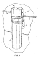
FIG. 1 is a perspective view of a filter assembly constructed in accordance with a representative preferred embodiment of the present disclosure; -
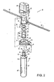
FIG. 2 is an exploded perspective view of the representative filter assembly ofFIG. 1 with parts separated for ease of illustration; -
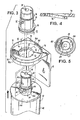
FIG. 3 is an enlarged perspective view of the repre sentative upper portion of the representative filter assembly ofFIG. 1 including the representative filter cartridge, representative support bracket and representative head member; -
FIG. 4 is a cross -sectional view of the representative support bracket sh own inFIG. 3 taken along line 4 -4 ofFIG. 3 illustrating the representative ramped camming surface formed thereon; -
FIG. 5 is bottom end view of the representative valve member shown inFIG. 3 as viewed along line 5 -5 ofFIG. 3 ; -
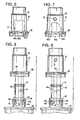
FIG. 6 is an elevational view of the representative valve member ofFIG. 3 , with a representative portion of the outer wall broken away to illustrate representative interior surface features thereof; -
FIG. 7 is an elevational view of the representative valve member ofFIG. 3 , with a representative portion of the outer wall broken away and rotated 180° from the position shown inFIG. 6 to illustrate representative interior surface features thereof; -
FIG. 8 is an elevational view of the representative upper portion of the filter cartridge and the valve member ofFIG. 3 , with the representative interlocking features thereof in axial alignment to facilitate the engagement therebetween; -
FIG. 9 is an elevational view of the representative upper portion of the representative filter cartri dge and the representative head member ofFIG. 3 , rotated 180° from the position shown inFIG. 8 , with the representative interlocking features thereof in axial alignment to facilitate the engagement therebetween; -
FIG. 10 is a perspective view of the repr esentative upper portion of the representative filter assembly of the present disclosure, with the representative wall of the representative head and representative valve members broken away to illustrate the initial position of the representative keyed ca mming lug of the representative filter relative to the representative ramped camming surface of the representative bracket member, wherein the representative valve assembly with which the representative head member is associated is closed to flow; -
FIG. 11 is a perspective view of the representative upper portion of the representative filter assembly of the present disclosure, with the representative wall of the representative head member broken away to illustrate the final position of the representative keyed camming lug of the representative filter relative to the representative ramped camming surface of the representative bracket member, wherein the representative valve assembly with which the representative head member is associated is open to flow; -
FIG. 12 is a perspective view of the representative cylindrical neck portion of the representative filter cartridge of the present disclosure, which includes camming lugs having a skeleton key formation; -
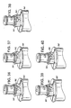
FIGS. 13-17 illustrate a variety of different key confi gurations provided on the camming lugs formed on the representative cylindrical neck portion of the representative filter cartridge of the present disclosure; -
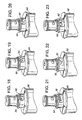
FIGS. 18-20 illustrate each of the available key patterns for a representative camming lug havin g a maximum of four teeth positions; -
FIGS. 21-27 illustrate each of the available key patterns for a representative camming lug having a maximum of five teeth positions; -
FIGS. 28-40 illustrate each of the available key patterns for a representative camming lug having a maximum of six teeth positions; -
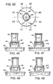
FIG. 41 is a top plan view of the neck portion of a representative filter cartridge constructed in accordance with a preferred representative embodiment of the present disclosure which includes three circumf erentially representative spaced camming lugs each having a different key formation thereon; -
FIG. 42 is a side elevational view of the representative neck portion of the representative filter cartridge ofFIG. 41 , taken along line 42 -42; -
FIG. 43 is a side elevational view of the representative neck portion of the representative filter cartridge ofFIG. 41 , rotated 120° from the view shown inFIG. 42 ; -
FIG. 44 is a side elevational view of the representative neck portion of the representative filter cartridge ofFIG. 41 , rotated 120° from the view shown inFIG. 43 ; -
FIG. 45 is a top plan view of the representative neck portion of a representative filter cartridge constructed in accordance with a preferred representative embodiment of the present disclosure w hich includes two sets of diametrically opposed camming lugs positioned at two different levels on the representative neck portion of the cartridge; -
FIG. 46 is a side elevational view of the representative neck portion of the representative filter cartrid ge ofFIG. 45 , taken along line 46 -46; -
FIG. 47 is a side elevational view of the representative neck portion of the representative filter cartridge ofFIG. 45 , rotated 90° from the view shown inFIG. 46 ; -
FIG. 48 is a side elevational view of the represen tative neck portion of the representative filter cartridge ofFIG. 45 , rotated 90° from the view shown inFIG. 47 ; -
FIG. 49 is a side elevational view of the representative neck portion of the representative filter cartridge ofFIG. 45 , rotated 90° from th e view shown inFIG. 48 ; -
FIG. 50 is a side elevational view in cross -section, of another representative filter assembly constructed in accordance with a preferred representative embodiment of the present disclosure wherein a representative ball valve is p ositioned within the assembly to inhibit the representative egress of fluid from the system when the filter cartridge is removed from the assembly, with the ball valve shown in an open position; -
FIG. 51 is a side elevational view in cross -section, of the representative filter assembly ofFIG. 50 with the ball valve shown in a closed position as the representative filter cartridge is removed from the assembly; -
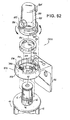
FIG. 52 is an exploded perspective view of another representative filter assembly constructed in accordance with a representative preferred embodiment of the present disclosure with the parts thereof separated for ease of illustration, including an annular insert in the form of a key ring having recesses designed to mate with corresponding surface fea tures on the keyed cam lugs of a replacement filter cartridge; and -
FIG. 53 is a perspective view of the representative filter assembly of theFIG. 52 with the head portion in cross -section to illustrate the interior structure thereof; - These and other features of the representative filter assembly of the present disclosure will become more readily apparent to those having ordinary skill in the art form the following detailed description of the representative preferred embodiments.
- Referring now to the figures wherein like reference numerals ident ify similar structural elements of the filter assembly of the subject disclosure, there is illustrated in
FIG. 1 a filter assembly constructed in accordance with a preferred representative embodiment of the subject disclosure and designated generally byre ference numeral 10.Filter assembly 10 is configured for use in conjunction with a fluid processing system that includes aninlet conduit 12 for delivering unfiltered process fluid into the filter assembly and anoutlet conduit 14 for delivering filtered p rocess fluid from thefilter assembly 10.Filter assembly 10 is preferably mounted to a supporting structure associated with the fluid processing system by abracket 16. - Referring to
FIG. 2 ,filter assembly 10 includes a uniquerotary valve assembly 18 that consists of ahead portion 20 defining an interior chamber having aninlet port 22 for communicating withinlet conduit 12 and anoutlet port 24 for communicating withoutlet conduit 14.Rotary valve assembly 18 further includes avalve member 26 config ured for reception within the interior chamber ofhead portion 20 in such a manner so as to facilitate rotation of the valve member relative to the head portion between an open position wherein fluid is permitted to flow through the filter assembly and a c losed position wherein flow through the filter assembly is restricted. (SeeFIGS. 10-11 ). -
Valve member 26 includes aninlet orifice 32 for communicating with theinlet port 22 ofhead portion 20 and anoutlet orifice 34 for communicating with theoutlet port 24 ofhead portion 20. (SeeFIGS. 6 -7 ). The body ofvalve member 26 includesrecesses ring seals ring seal 36 serves to sealingly isolate the inlet flow from the outlet flow within the interior chamber ofhead portion 20 during operation, while O -ring seal 38 8 prevents leakage to atmosphere. - With continuing reference to
FIG. 2 ,filter assembly 10 further includes areplaceable filter cartridge 40 constructed in accordance with a preferred representative embodiment of the present disclosure.Filter assembly 10 is adapted and configured to ensure thatreplacement cartridge 40 is compatible with the fluid processing system with which it is associated. Moreover, as discussed hereinbelow, thefilter cartridge 40 andvalve portion 26 are provided with keyed mating structures that ensure compatibility therebetween, and thus prevent the accidental or intentional installation of an incompatible or inferior replacement cartridge, which could jeopardize the integrity of the fluid processing system. - Referring to
FIG. 3 ,replaceable filter cartridge 40 includes a generallycylindrical body portion 42 enclosing filter media for filtering process fluid. Those skilled in the art will readily appreciate that any one of a variety of different types of filter media could be enclosed within the body portion including, for example, pleated media, micro -fibers or carbon media. Anend cap 44 encloses thebody portion 42, and acylindrical neck portion 46 depends from t he endcap 44. Those skilled in the art will readily appreciate that theend cap 44 andbody portion 42 can be joined together by sonic welding, spin welding or other similar methods known in the art. Theneck portion 46 offilter cartridge 40 is adapted a nd configured for reception with the interior cavity of valve member 26 (seeFIGS. 6 -9 ) and includes an upper section 46a and a lower portion 46b. As would be understood by those skilled in the art, one of a plurality of possible alternative representative embodiments could include areplaceable filter cartridge 40 wherein there is no difference in the diameter of thecylindrical body portion 42 and thecylindrical neck portion 46, thus, there is no differentiation between thecylindrical bottom portion 42 and thecylindrical neck portion 46 and, thus, the location of the cam lugs 62 and 64 need only be operatively positioned on thereplaceable filter cartridge 40 such that thefilter cartridge 40 is operatively connected to the intermediate support flange 7 0 that depends from mountingbracket 16. - The upper section 46a defines a
radial inlet passage 52 for receiving unfiltered process fluid entering thevalve member 26 throughinlet orifice 32 and directing the fluid into thebody portion 42 offilter cartri dge 40. The upper section 46a further defines anaxial outlet passage 54 for delivering filtered process fluid from the interior ofbody portion 42 to the interior cavity ofvalve member 26 for egress through theoutlet orifice 34 into the interior chamber ofhead portion 20. Those skilled in the art will readily appreciate that the inlet and outlet passages in the neck portion could be reversed such that the inlet flow is axial and the outlet flow is radial. The inlet andoutlet passages ring seal 56 positioned at the upper end ofneck portion 46. A second lower O -ring seal 58 8 is positioned below theradial inlet passage 52 to sealingly engage theneck portion 46 within the interior chamber of thevalve member 26 and prevent the leakage of unfiltered process fluids fromfilter assembly 10 while in operation. - Referring to
FIG. 2 in conjunction withFIG. 3 , presently preferably, a pair of diametrically opposed inclined cam lugs 62 and 64 project radially outwardly from the lower section 46b ofneck portion 46. Cam lugs 62 and 64 are dimensioned and configured to facilitate rotational engagement of the filter cartridge within anintermediate support flange 70 that depends from mountingbracket 16. As best seen inFIG. 3 , acentral aperture 75 extends throughsupport flange 70 for receiving theneck portion 46 offilter cartridge 40. A pair of diametrically opposed cam ramps 72 and 74 project radially intocentral aperture 75 for interacting with the inclined lower surfaces of cam lugs 62 and 64. The cam ramps 72 and 74 are spaced from one another to allow the cam lugs 62 and 64 to fit therebetween when the neck portion is extended throughaperture 75 during assembly, and they are inclined along their arc length to facilitate rotational engagement of the filter cartridge withsupport flange 70, as illustrated inFIG. 4 . - Referring to
FIGS. 2 and3 ,support flange 70 further includes a recessedseating area 76 defined byannular retaining wall 78 and co nfigured to receive and retain thehead portion 20 offilter assembly 10. Diametrically opposedarcuate retention ribs wall 78 to frictionally engage with corresponding ramped engagement struts 92 and 94 that project radially outwardly from the lower region ofhead portion 20 when thehead portion 20 is rotatably engaged within the recessedseating area 76 during assembly. Stop surfaces 82a and 84a are associated withretention ribs head portion 20 withinseating area 76. In an alternate representative embodiment, thehead portion 20 andsupport flange 70 may be adapted and configured to cooperate and engage with one another in a manner described hereinbelow with respect to filterassembly 800 and illustrated inFIGS. 52 -53 . - As best seen in
FIGS. 1 and2 , theannular retaining wall 78 ofsupport flange 70 is also configured to accommodate and support ashroud 90, which is configured to house and protect therotary valve assembly 18 offilter assembly 10. As illustrated, theshroud 90 includes lateral apertures, i.e.,aperture 92, for accommodating inlet andoutlet conduits support flange 70 could vary depending upon the nature of the operating environment within which the system is employed. - Referring to
FIG. 5 , in accordance with a presently preferred representative embodiment of the present disclosure, cam lugs 62 and 64 are adapted and configured for reception within a pair of corresponding diametrically opposedreception areas interior cavity 25 ofvalve member 26. More particularly, the upper surface of eachcam lug valve member 26. This mating arrangement is designed to ensure replacement cartridge compatibility by only permitting replacement of a filter cartridge having a keyed surface formation that corresponds with the surface features of the reception areas in the valve member. - In the exemplary representative embodiment of the disclosure illustrated in
FIGS. 3-9 , the key formation on each cam lug (62, 64) includes three spaced apart teeth (62a-62c, 64a-64c) and each reception area (102, 104) within thevalve member 26 includes three corresponding recesses (102a -102c, 104a-104c) for accommodating the teeth when theneck portion 46 ofcartridge 40 is received byvalve member 26. - As discussed in greater detail hereinbelow, the num ber of teeth that define the key formation on each cam lug can vary within the scope of this disclosure (see for example
FIGS. 18 -40 ), as can the surface geometry of the key formation (see for exampleFIGS. 13-17 ). In each instance, the reception area in t he rotary valve member would have a corresponding mating configuration to accommodate the key formation formed on the cam lugs. Furthermore, it is envisioned that the key configuration on one lug could be different from the key configuration of the opposed lug. This will dramatically increase the number of possible key combinations available to a filter manufacturer. - Referring to
FIG. 10 , when a compatible filter cartridge is introduced into thefilter assembly 10 of the subject disclosure, theneck portio n 46 of thefilter cartridge 40 is inserted through thecentral aperture 75 ofsupport flange 70, with the cam lugs 62 and 64 positioned between the diametrically opposed cam ramps 72 and 74. At such a time, thevalve member 26 is in the "off' position to receive theneck portion 46. Thus, the inlet andoutlet orifices valve member 26 are not aligned with the inlet andoutlet ports head portion 20. Thereupon, the teeth (62a -62c, 64a-64c) forming the keyed engagement surface of cam lugs 6 2 and 64 extend into the corresponding recesses (102a-102c, 104a-104c) of recessedareas - Once the
neck portion 46 offilter cartridge 40 has been intimately engaged within the interior chamber ofvalve member 26, the cartri dge and valve member may be rotated in a counter -clockwise direction with respect to thesupport flange 70 andhead portion 20, as illustrated inFIG. 11 . Upon rotatingfilter cartridge 40 in conjunction withvalve member 26, the cam lugs 62, 64 projecting fromneck portion 46 translate against the cam ramps 72, 74, causing thefilter cartridge 40 to move helically upwardly in an axial direction. As a result,valve member 26 is rotated into the "on" or open position, wherein the inlet andoutlet orifices valve member 26 are aligned with the inlet andoutlet ports head portion 20 to allow fluid to flow through thefilter assembly 10. - If the cam lugs of a replacement filter cartridge introduced into the system are not configured to mate with the reception areas of the valve member, i.e., if the cam lugs have no keyed surface formation, which may be indicative of an unauthorized after-market filter cartridge, the cam lugs will interfere with and be unable to engage the reception areas in the valve member. Consequently, because the inclined cam surfaces of the cam lugs 62, 64 will be located below the inclined surfaces of the cam ramps 72, 74, the cam lugs will be unable to traverse the cam ramps. As a result, the cam lugs will be unable to effect rotation of the valve member into the "on" position to permit fluid to flow through the assembly. This will ensure replacement cartridge compatibility by preventing the use of inferior or unauthorized replacement filter cartridges.
- The key formation shown in the exemplary representative embodiment of
FIGS. 3-11 , corresponds to the key formation illustrated inFIG. 22 , which is selected from a group of key formations having five available tooth positions. In the exemplary representative embodiment, the first, fourth and fifth teeth are present, while the second and third teeth are absent. Using the convention wherein the numeral "1" represents the presence of a tooth in a position of a key formation, and the numeral "0" represents the absence of a t ooth in a position of the key formation, the key formation illustrated inFIGS. 3 -11 , and22 may be represented by the numerical expression (1, 0, 0, 1, 1). - In accordance with a preferred representative embodiment of the subject disclosure, there exists a replacement cartridge that is provided with cam lugs having a surface formation that is compatible with a rotary valve member regardless of the number of recesses defined within the recessed areas formed therein. A cartridge having a neck portion with dia metrically opposed cam lugs that include such a formation referred to herein as a skeleton key formation, is illustrated in
FIGS. 2 and12 and is designated generally byreference numerals - Referring to
FIG. 12 , the cam lugs 162 and 164 offilter cartridge 140 includes a skeleton key formation defined by a tooth formation wherein only the first and fifth tooth positions are filled with teeth (i.e., teeth 162a, 162b). This skeleton key is represented by the numerical expression (1, 0 , 0, 0, 1). It should be understood that, in a five position key formation, the first and fifth position will always be filled, and, conversely, the recessed areas of the valve member will always have a recess located in the complementary positions. - Table 2 below, sets forth the available tooth combinations for the five position key formation associated with the opposed cam lugs 162 and 164 of
filter cartridge 140 and illustrated inFIGS. 3 -11 and21-27 . In total, excluding the skeleton key formation ofFIG. 12 , there are seven available tooth configurations for a five position key formation. Table 1 below sets forth the available tooth configurations for the four position key formation associated with the opposed cam lugs 262 and 264 offilter cartridge 24 0 illustrated inFIGS. 18 -20 . In total, excluding the skeleton key formation which is not shown and is represented by the numerical expression (1, 0, 0, 1) there are three available tooth configurations for a four position key formation. Table 3 sets forth the available tooth configurations for the six position key formation associated with the opposed cam lugs 362 and 364 ofreplaceable filter cartridge 340 as illustrated inFIGS. 28 -41 . In total, excluding the skeleton key formation which is not shown and is represented by the numerical expression (1, 0, 0, 0, 0, 1) there are fifteen available tooth configurations for a six position key formation.TABLE 1 Tooth Configurations (Four Positions) Figure 1, 1, 1, 1 18 1, 1, 0, 1 19 1, 0, 1, 1 20 TABLE 2 Tooth Configurations (5 positions) Figure 1, 1, 1, 1 1 21 1, 0, 0, 1, 1 22 1,0, 1, 0, 1 23 1, 1, 0, 1, 1 24 1, 1, 1, 0, 1 25 1, 0, 1, 1, 1 26 1, 1, 0, 0, 1 27 TABLE 3 Tooth Configurations (6 positions) Figure 1, 1, 1, 1, 1, 1 28 1, 1, 0, 0, 0, 1 29 1, 1, 1, 0, 0, 1 30 1, 1, 1, 1, 0, 1 31 1, 0, 0, 0, 1, 1 32 1, 0, 0, 1, 1, 1 33 1, 0, 1, 1, 1, 1 34 1, 1, 0, 0, 1, 1 35 1, 1, 0, 1, 1, 1 36 1, 1, 1, 0, 1, 1 37 1, 0, 1, 1, 0, 1 38 1, 1, 0, 1, 0, 1 39 1, 0, 1, 0, 1, 1 40 1, 0, 1, 0, 0, 1 not shown 1, 0, 0, 1, 0, 1 not shown - In summary, the number of available tooth combinations "N" for a given tooth configuration having "n" tooth positions can be expressed mathematically as follows: N=2n-2-1
- The relatively large number of key configur ation that are available though the keyed system of the subject disclosure will give original equipment manufacturers the ability to provide customized filters for each of their appliances. Thus, each manufacturer could offer a unique set of replacement fil ter cartridge, with each cartridge in the set having a different keyed surface formation provided on the camming lugs thereof, for mating with corresponding reception areas in a valve member supported within a particular type of appliance.
- Referring to
FIGS. 13-17 , there are illustrated a series of replacement filter cartridges constructed in accordance with a preferred representative embodiment of the subject disclosure each having a different keyed surface formation associated therewith. For example, FIG S. 13, 14, 16 and 17 illustratefilter cartridges cam lug 463 inFIG. 13 includes twoteeth 463a, 463b which project axially and radially from the lug.Cam lug 464 inFIG. 14 includes two axially projecting teeth 464a and 464c and one tooth 464b that project both radially and axially.FIG. 16 illustrates acam lug 466 having an enlarged radially and axially projecting tooth 466a and a smaller axially projecting tooth 466b.Cam lug 467 inFIG. 17 includes two axially projecting teeth 467a and 467b and the majority of the cam lug itself project radially outwardly from the neck portion of thefilter cartridge 407. In accordance with the subject disclosure, it follows that a compatible rotary valve member would have recessed areas with mating features that correspond to the radially and axially exte nding keyed surface formations of cam lugs 463, 464, 466 and 467. -
FIG. 15 , illustrates anotherreplacement filter cartridge 405 constructed in accordance with a preferred representative embodiment of the subject disclosure wherein the keyed surface format ion provided on thecam lug 465 thereof is defined by acurved surface 465a. In accordance with the subject disclosure, a compatible valve member forfilter cartridge 405 would have reception areas with corresponding curved recesses to ensure compatibility withcartridge 405. - Referring to
FIGS. 41 -44 , there is illustrated another replacement filter cartridge constructed in accordance with a preferred representative embodiment of the subject disclosure and designated generally byreference numeral 540. Filt ercartridge 540 includes three cam lugs 561, 562 and 563 that are circumferentially spaced apart about the periphery of neck portion 546. Each cam lug has a keyed surface formation thereon for mating with a corresponding recessed area of a compatible rotary valve member 26. As illustrated inFIGS. 42 -44 , the keyed surface formations of cam lugs 561-563 are derived from a five tooth configuration (see Table 2), and each cam lug has a different key pattern formed thereon. In particular,cam lug 561 has a fir st keyed surface formation that may be represented by the numerical expression (1, 0, 1, 0, 1),cam lug 562 has a second keyed surface formation that may be represented by the numerical expression (1, 0, 0, 1, 1), andcam lug 563 has a third keyed surface formation that may be represented by the numerical expression (1, 1, 0, 0, 1). It is also envisioned that cam lugs 561 -563 could each have the same keyed surface formation provided thereon. - Referring to
FIGS. 45 -49 , there is illustrated another replacement filter cartridge constructed in accordance with a preferred representative embodiment of the subject disclosure and designated generally byreference numeral 640.Filter cartridge 640 includes two sets of diametrically opposed cam lugs that include cam 1 ugs 661-664. The first set of opposed cam lugs 661, 663 are positioned at a first axial height onneck portion 646, and the second set of opposed cam lugs 662, 664 are positioned at a second axial height onneck portion 646. In addition, each cam lug has a keyed surface formation thereon for mating with a corresponding recessed area of a compatiblerotary valve member 26. As illustrated inFIGS. 46 -49 , the keyed surface formations of cam lugs 661-664 are derived from a five tooth configuration (see Table 2) . Cam lugs 661 and 664 have the same keyed surface formation thereon that may be represented by the numerical expression (1, 0, 0, 1, 1), while cam lugs 662 and 663 both have another keyed surface formation thereon that may be represented by the numerical expression (1, 1, 0, 0, 1). It is also envisioned that cam lugs 661 -664 could each have the same keyed surface formation provided thereon, or, in the alternative, each cam lug could have a different keyed surface formation provided thereon. - Referring to
FIGS. 50-51 , there is illustrated another filter assembly constructed in accordance with a preferred representative embodiment of the subject disclosure and designated generally byreference numeral 700.Filter assembly 700 includes ahead portion 720 enclosing arotary valve member 726 that has a mechanism for minimizing leakage during cartridge replacement. The mechanism includes a floating check -ball 728 and an associatedvalve seat 730. As shown inFIG. 51 , during normal service, when process fluid is fl owing through the system, the outlet flow pressure of the filtered fluid causes the check -ball 728 to remain in an unseated position. In contrast, when theneck portion 46 of areplacement filter cartridge 40 is removed from the interior bore of valve memb er 726, and the outlet flow pressure is terminated, the check -ball 728 becomes seated invalve seat 730, as shown inFIG. 51 . As a result, the void volume withinhead portion 720 is restricted from flowing out ofvalve member 726. - Referring now to
FIGS. 52-53 , there is illustrated another filter assembly constructed in accordance with a preferred representative embodiment of the subject disclosure and designated generally byreference numeral 800.Filter assembly 800 differs from the previously described representative embodiments of the subject disclosure in that the assembly does not include a rotary valve member, such as thevalve member 18 offilter assembly 10. Instead, as best seen inFIG. 53 ,filter assembly 800 includes ahead portion 820 with an in terior bore 825 having a lower region 825a configured to support an annular insert in the form of akey ring 818.Key ring 818 defines diametrically opposedreception areas neck portion 26 of areplacement filter cartridge 40, for example. In accordance with the subject disclosure, to ensure the integrity of the system with whichfilter assembly 800 is associated, a compatible replacement cartridge must have cam lugs with keyed surface formations that mate with the recessed areas of thekey ring 818. - Referring to
FIG. 52 ,filter assembly 800 further includes a mountingbracket 816 having asupport flange 870 depending therefrom for facilitating rotational engagement of areplacement filter cartridge 40 withhead member 820 and the associatedkey ring 818. Acentral aperture 875 extends throughsupport flange 870 to receive theneck 46 offilter cartridge 40, and a pair of diametrically opposed cam raps 872 and 874 project radially intocentral aperture 875 for operatively interacting with the inclined lower surfaces of cam lugs 62, 64 whenfilter cartridge 40 is engaged withhead portion 820.Support flange 870 further includes a recessedseating area 876 defined by anannular retaining wall 878 configured to receive and retain thehead portion 820. More particularly,head portion 820 includes a pair of diametrically opposed ramped cam struts 882 and 884 for operatively engaging a pair of diametrically opposedretention flanges wall 878. In addition, ratchet nibs 882a and 884a project outwardly from the lower region ofhead portion 820 for engagement withincorresponding notches retention flanges head portion 820 andsupport flange 870 interact and engage may also be employed in conjunction with thefilter assembly 10 described herein above, wherebyhead portion 20 andsupport flange 70 would be adapted and configured to interact and engage in a substantially similar manner. - To assemble the
filter assembly 800 of the subject disclosure, akey ring 818 having particular configuration of recesses, which may be selected from a set of key rings each having different recess configurations, is first inserted into the lower region 825a ofinterior bore 825 ofhead potion 820. The head portion is then rotatably engaged within the seating area 8 76 ofsupport flange 870. Thereafter, afilter cartridge 40 is brought into approximation with thehead portion 820 by inserting theneck portion 46 of the cartridge through thecentral aperture 875 ofsupport flange 870, allowing the camming lugs 62, 64 to pass between the opposed cam ramps 872, 874 projecting radially intoaperture 875. At such a time, the keyed surface formations of the cam lugs 62, 64 mate with the corresponding recessedareas key ring 818, provided of course that the cartri dge and key ring are compatible with one another. Once the cam lugs 62, 64 are mated with the recessedareas filter cartridge 40 is rotated through an arc of approximately 90°, such that the inclined lower surfaces of cam lugs 62, 64 translat e relative to cam ramps 872, 874. This relative movement causes thekey ring 818 to rotate within interior bore region 825a and causes theneck portion 46 offilter cartridge 40 to move axially into the upper region 825b of theinterior bore 825 ofhead po rtion 820, until such time as the neck portion of the filter cartridge is sealingly received therein. - It should be noted that provision is made such that
key ring 818 will rotate through a limited travel range relative to thehead portion 820 as filter ca rtridge 40 is rotated into engagement withhead portion 820. Furthermore, since a rotary valve member is not utilized withhead portion 820, the upper region 825b ofinterior bore 825 is dimensioned and configured to directly mate with theneck portion 46 offilter cartridge 40, such that theinlet port 52 inneck portion 46 is in direct fluid communication with theradial inlet port 812 ofhead portion 820 and theaxial outlet port 54 inneck portion 46 is in direct fluid communication with the radial outl etport 814 ofhead portion 820. - Although the disclosed fluid filtration apparatus has been described with respect to exemplary, representative, presently preferred embodiments, it is app arent that modifications and changes can be made thereto without departing from the and scope of the invention as defined by the appended embodiments.
Claims (14)
- A filter cartridge (40) comprising:a body portion (42) configured to contain at least one filter media; anda cylindrical neck portion (46) depending from the body portion;wherein the neck portion comprises an inlet port (32) for directing a fluid into the body portion, an outlet port (34) for directing the fluid out of the body portion, and at least two diametrically opposite lugs (62 ; 64) depending radially outwardly therefrom, each of the at least two lugs comprising:an inclined cam surface (72 ; 74) facing substantially toward the body portion; anda keyed surface formation (62a-62c; 64a-64c) comprising at least one axially projecting tooth (162a) facing substantially away from the body portion.
- The filter cartridge of claim 1 wherein the keyed surface formation is configured to engage a complimentary keyed surface formation (102a-102c; 104a-104c) on a corresponding reception assembly (102 ; 104).
- The filter cartridge of any of claims 1-2 wherein the keyed surface formation of one lug is different from the keyed surface formation of at least one other lug.
- The filter cartridge of any of claims 1-3 wherein each at least one axially projecting tooth is disposed in a tooth position of a defined tooth configuration.
- The filter cartridge of claim 1 further comprising at least one radially projecting tooth facing substantially away from the neck portion.
- The filter cartridge of any of claims 5 wherein the keyed surface formation is configured to engage a complimentary keyed surface formation on a corresponding reception assembly.
- The filter cartridge of any of claims 5-6 wherein the keyed surface formation of one lug is different from the keyed surface formation of at least one other lug.
- The filter cartridge of any of claims 5-7 wherein each at least one axially projecting tooth (464a) is disposed in a tooth position of a defined tooth configuration.
- The filter cartridge of any of claims 5-8 wherein each at least one radially projecting tooth (463a) is disposed in a tooth position of a defined tooth configuration.
- The filter cartridge of any of claim s 1-9 wherein the keyed surface formation comprises at least one to oth that projects from the lug both radially and axially (463a).
- The filter cartridge of any of claims 4 or 8-9 wherein the defined tooth configuration comprises one of 4 tooth positions, 5 tooth positions, or 6 tooth positions.
- The filter cartridge of any of claims 4, 8-9, or 11 wherein the tooth configuration comprises a number of available tooth combinations:

wherein "n" is the number of tooth positions. - The filter cartridge of any of claims 1-12 wherein the keyed surface formation of each lug is different.
- A method of making a filter cartridge (40) according to claim 1 comprising:forming a body portion (42) configured to contain at least one filter media;forming a neck portion (46) depending from the body portion , wherein the neck portion comprises an inlet port (32) for directing a fluid into the body portion and an outlet port (34) for directing the fluid out of the body portion;forming at least two lugs (62 ; 64) depending radially outwardly from the neck portion, wherein each lug comprises an inclined cam surface (72, 74) facing substantially toward the body portion;configuring a keyed surface formation (62a-62c; 64a-64c) comprising at least one axially projecting tooth (162a) facing substantially away from the body portion the keyed surface formation for reception within corresponding surface features of a reception area of a valve member (102; 104);forming the keyed surface formation onto the inclined cam surface of at least one lug.
Applications Claiming Priority (2)
| Application Number | Priority Date | Filing Date | Title |
|---|---|---|---|
| US09/553,982 US6458269B1 (en) | 2000-04-20 | 2000-04-20 | Keyed filter assembly |
| EP01928615A EP1274494B1 (en) | 2000-04-20 | 2001-04-18 | Keyed filter assembly |
Related Parent Applications (1)
| Application Number | Title | Priority Date | Filing Date |
|---|---|---|---|
| EP01928615A Division EP1274494B1 (en) | 2000-04-20 | 2001-04-18 | Keyed filter assembly |
Publications (2)
| Publication Number | Publication Date |
|---|---|
| EP2151267A1 EP2151267A1 (en) | 2010-02-10 |
| EP2151267B1 true EP2151267B1 (en) | 2014-06-11 |
Family
ID=24211571
Family Applications (2)
| Application Number | Title | Priority Date | Filing Date |
|---|---|---|---|
| EP09173789.0A Expired - Lifetime EP2151267B1 (en) | 2000-04-20 | 2001-04-18 | Rotary valve assembly for fluid filtration system |
| EP01928615A Expired - Lifetime EP1274494B1 (en) | 2000-04-20 | 2001-04-18 | Keyed filter assembly |
Family Applications After (1)
| Application Number | Title | Priority Date | Filing Date |
|---|---|---|---|
| EP01928615A Expired - Lifetime EP1274494B1 (en) | 2000-04-20 | 2001-04-18 | Keyed filter assembly |
Country Status (7)
| Country | Link |
|---|---|
| US (6) | US6458269B1 (en) |
| EP (2) | EP2151267B1 (en) |
| JP (1) | JP4854905B2 (en) |
| AU (2) | AU2001255452B2 (en) |
| BR (1) | BR0110311B1 (en) |
| DE (1) | DE60140528D1 (en) |
| WO (1) | WO2001080967A1 (en) |
Cited By (5)
| Publication number | Priority date | Publication date | Assignee | Title |
|---|---|---|---|---|
| USD847944S1 (en) | 2016-05-11 | 2019-05-07 | Hong Kong Ecoaqua Co., Limited | Filter cartridge |
| USD847945S1 (en) | 2016-05-11 | 2019-05-07 | Hong Kong Ecoaqua Co., Limited | Filter cartridge |
| USD847946S1 (en) | 2016-05-11 | 2019-05-07 | Hong Kong Ecoaqua Co., Limited | Filter cartridge |
| USD849188S1 (en) | 2016-05-11 | 2019-05-21 | Hong Kong Ecoaqua Co., Limited | Filter cartridge |
| GB2576609A (en) * | 2018-06-26 | 2020-02-26 | Atlas Copco Airpower Nv | Filter device and method for mounting such a filter device |
Families Citing this family (184)
| Publication number | Priority date | Publication date | Assignee | Title |
|---|---|---|---|---|
| US7407148B2 (en) * | 2000-04-20 | 2008-08-05 | 3M Innovative Properties Company | Rotary valve assembly for fluid filtration system |
| US6458269B1 (en) | 2000-04-20 | 2002-10-01 | Cuno Incorporated | Keyed filter assembly |
| US6949189B2 (en) * | 2000-04-20 | 2005-09-27 | Cuno Incorporated | Keyed filter assembly |
| EP1322399B1 (en) * | 2000-08-11 | 2011-07-13 | Omnipure Filter Company, Inc. | Keyed system for connection of filter cartridge to filter holder |
| US9314722B2 (en) | 2000-08-11 | 2016-04-19 | Omnipure Filter Company, Inc. | Keyed system for connection of filter cartridge to filter holder |
| US20110203985A1 (en) * | 2009-08-21 | 2011-08-25 | Omnipure Filter Company, Pllc | Keyed system for connection of filter to filter holder |
| US7476314B2 (en) * | 2000-08-11 | 2009-01-13 | Reid Roger P | Keyed system for connection of filter cartridge to filter holder |
| FR2831855B1 (en) | 2001-11-06 | 2004-04-02 | Gemplus Card Int | ARRANGEMENT FOR SUPPLYING A FLUID TO A MACHINE COMPRISING FALLING MEANS |
| US7638042B2 (en) * | 2002-02-15 | 2009-12-29 | 3M Innovative Properties Company | System for monitoring the performance of fluid treatment cartridges |
| US20030168389A1 (en) * | 2002-02-15 | 2003-09-11 | Astle Robert E. | System for monitoring the performance of fluid treatment cartridges |
| TWI269665B (en) * | 2002-02-21 | 2007-01-01 | Roger P Reid | Quick change filter and bracket system with key system and universal key option |
| GB2389323B (en) * | 2002-06-07 | 2005-08-17 | Baldwin Filters Inc | Environmentally friendly filter cartridge |
| US6843911B2 (en) * | 2002-10-31 | 2005-01-18 | Stanadyne Corporation | Base receptacle with fixed retainer for filter cartridge incorporating a peripheral compatibility matrix |
| US6923910B2 (en) * | 2003-01-07 | 2005-08-02 | Cuno Incorporated | Filter cartridge having bypass feature |
| US6868988B2 (en) * | 2003-02-28 | 2005-03-22 | Nestec S.A. | Containers of flowable substance adapted for connecting to dispensing devices of a beverage or food dispensing machine |
| USD494654S1 (en) | 2003-04-25 | 2004-08-17 | Procter & Gamble Co. | Fluidic cartridge fittings |
| USD492753S1 (en) | 2003-04-25 | 2004-07-06 | Procter & Gamble | Fluidic cartridge end piece |
| US7000894B2 (en) * | 2003-04-25 | 2006-02-21 | Pur Water Purification Products, Inc. | Fluidic cartridges and end pieces thereof |
| EP1631370A4 (en) * | 2003-05-02 | 2008-07-09 | 3M Innovative Properties Co | Crossflow filtration system with quick dry change elements |
| NL1023520C2 (en) * | 2003-05-23 | 2004-11-24 | Sgt Singapore Holdings Pte Ltd | Quick-change filter system as well as a base and a quick-change filter intended for such a system. |
| US7673756B2 (en) | 2005-06-29 | 2010-03-09 | Selecto, Inc. | Modular fluid purification system and components thereof |
| US20050023206A1 (en) * | 2003-07-29 | 2005-02-03 | Karl Fritze | Water filter adapter with locking feature |
| US7294262B2 (en) | 2003-08-27 | 2007-11-13 | Sta-Rite Industries, Llc | Modular fluid treatment apparatus |
| US20050244810A1 (en) * | 2003-09-29 | 2005-11-03 | Egan Josephine M | Taste signaling in gastrointestinal cells |
| DE102004014149B4 (en) * | 2004-03-20 | 2007-01-25 | Hydac Filtertechnik Gmbh | filter means |
| US6977039B2 (en) * | 2004-03-30 | 2005-12-20 | Natural Choice Corporation | Fluid filter apparatus and method |
| WO2006012031A1 (en) | 2004-06-29 | 2006-02-02 | Donaldson Company, Inc. | Liquid filter arrangement and methods |
| KR100634782B1 (en) * | 2004-10-01 | 2006-10-17 | 삼성전자주식회사 | Water Purifier |
| CN2741960Y (en) * | 2004-10-28 | 2005-11-23 | 厦门建霖卫浴工业有限公司 | Water purifier |
| CA2771265C (en) | 2005-01-27 | 2014-05-06 | Ecowater Systems, Llc | Encapsulated water treatment system |
| US7481926B2 (en) * | 2005-02-15 | 2009-01-27 | Mann & Hummel Gmbh | Filter device |
| BRPI0606908A2 (en) * | 2005-02-22 | 2009-07-28 | Baldwin Filters Inc | filter apparatus |
| US8057669B2 (en) * | 2005-02-22 | 2011-11-15 | Baldwin Filters, Inc. | Filter element and filter assembly including locking mechanism |
| DE202005007870U1 (en) * | 2005-05-13 | 2006-09-21 | Mann + Hummel Gmbh | Filter device, in particular for liquid filtration in internal combustion engines |
| CN101198390B (en) * | 2005-05-16 | 2010-10-06 | 3M创新有限公司 | Column Valve Manifold Interconnect Construction for Filtration Systems |
| JP4847526B2 (en) * | 2005-07-20 | 2011-12-28 | スリーエム イノベイティブ プロパティズ カンパニー | Fluid filtration system |
| CA2573486A1 (en) * | 2006-01-10 | 2007-07-10 | Moen Incorporated | Water filtration system |
| US20070158258A1 (en) * | 2006-01-11 | 2007-07-12 | Martin Blaze | Multiple flow integral filtration manifold |
| US7651070B2 (en) * | 2006-01-19 | 2010-01-26 | Clean & Clear Corporation | Canter element controlled combination manifold, valve and filter module system |
| KR20080104322A (en) * | 2006-03-22 | 2008-12-02 | 쓰리엠 이노베이티브 프로퍼티즈 컴파니 | Liquid filtration systems |
| US8252173B2 (en) | 2006-04-05 | 2012-08-28 | Aquis Wasser-Luft-Systeme Gmbh, Lindau Zweigniederlassung Rebstein | Water filter cartridge system having a combined blending valve system in the candle and adjusting device in the head |
| DE102007010129B4 (en) * | 2006-04-05 | 2022-09-15 | Aquis Wasser-Luft-Systeme Gmbh, Lindau, Zweigniederlassung Rebstein | Water filter cartridge system with combined blending valve technology in the candle and adjustment device in the head |
| US20070284296A1 (en) | 2006-06-08 | 2007-12-13 | Paragon Water Systems | Filter cartridge and head assembly with internal shutoff valve |
| KR20090024809A (en) * | 2006-06-27 | 2009-03-09 | 코닌클리케 필립스 일렉트로닉스 엔.브이. | Water purification system and filter element for this system |
| US20080000820A1 (en) * | 2006-06-30 | 2008-01-03 | Mitchell Alan J | Water Filter Cartridge and Valve with Autobypass Feature |
| KR100646182B1 (en) * | 2006-07-10 | 2006-11-15 | 정휘동 | Water purifier filter assembly |
| US7862720B2 (en) * | 2006-08-09 | 2011-01-04 | Aquamira Technologies, Inc. | Portable filtration system |
| ES2545952T3 (en) | 2006-08-10 | 2015-09-17 | Aquis Wasser-Luft-Systeme Gmbh, Lindau | Deposit |
| US8349180B2 (en) * | 2006-09-05 | 2013-01-08 | Pall Corporation | Filter elements and assemblies |
| DE102006044744C5 (en) * | 2006-09-20 | 2021-04-01 | Aquis Wasser-Luftsysteme GmbH Lindau, Zweigniederlassung Rebstein | Water filter device with encryption structure |
| US20080149556A1 (en) * | 2006-12-22 | 2008-06-26 | Quigley George T | Horizontal sanitary lenticular cartridge housing assembly |
| WO2008077609A2 (en) * | 2006-12-22 | 2008-07-03 | Aquis Wasser-Luft-Systeme Gmbh, Lindau, Zweigniederlassung Rebstein | Water filter device with depletion display |
| KR20080083903A (en) * | 2007-03-13 | 2008-09-19 | 삼성전자주식회사 | Water Purifier |
| GB0715247D0 (en) * | 2007-08-04 | 2007-09-12 | Parker Hannifin Ltd | Filter assembly |
| GB0715269D0 (en) * | 2007-08-04 | 2007-09-12 | Parker Hannifin Ltd | Filter assembly |
| US20100264078A1 (en) * | 2007-10-29 | 2010-10-21 | Bassett Laurence W | Latch reset filter unit |
| EP2092970B1 (en) | 2008-02-08 | 2011-05-18 | ARGO-HYTOS GmbH | Filter device for filtering a liquid |
| US7662283B2 (en) * | 2008-03-21 | 2010-02-16 | Pentair Filtration, Inc. | Modular drinking water filtration system with locking arrangement to assure filter cartridge compatibility |
| US7540957B1 (en) * | 2008-03-21 | 2009-06-02 | Pentair Filtration, Inc. | Modular drinking water filtration system with bottom load cartridges with grip-enhanced end rings and color coding |
| US7540956B1 (en) | 2008-03-21 | 2009-06-02 | Pentair Filtration, Inc. | Modular drinking water filtration system with removable and replaceable RO spindle |
| US20090236272A1 (en) * | 2008-03-21 | 2009-09-24 | Pentair Filtration, Inc. | Modular Drinking Water Filtration System with Keyed Attachment of Filter Head to Mounting Bracket and Modular Back Plates |
| US7695619B2 (en) * | 2008-03-21 | 2010-04-13 | Pentair Filtration, Inc. | Modular drinking water filtration system with adapter rings for replaceable cartridges to assure proper fit |
| US9782706B1 (en) | 2008-04-16 | 2017-10-10 | Selecto, Inc. | Flow connector for connecting screw-type filtration head to lug-type sump |
| CN101579591B (en) * | 2008-05-16 | 2011-03-09 | 鞍钢股份有限公司 | Coating filter equipment with alarming function |
| US8586338B2 (en) | 2008-05-30 | 2013-11-19 | 3M Innovative Properties Company | Ligand functionalized substrates |
| CN102083897B (en) | 2008-05-30 | 2013-06-12 | 3M创新有限公司 | Method of making ligand functionalized substrates |
| US8128819B2 (en) | 2008-06-16 | 2012-03-06 | Baldwin Filters Inc. | Fluid filter, fluid filter assembly, and mounting method |
| US8815090B2 (en) * | 2008-06-16 | 2014-08-26 | Baldwin Filters, Inc. | Filter with water separation device |
| US8241493B2 (en) | 2008-06-16 | 2012-08-14 | Baldwin Filters, Inc. | Filter with ejection mechanism |
| DE102008002727B4 (en) * | 2008-06-27 | 2020-12-17 | Brita Gmbh | Device for treating water, in particular a filter device, and cartridge |
| WO2010011483A2 (en) * | 2008-07-21 | 2010-01-28 | 3M Innovative Properties Company | Apparatus for dispersing additive into a fluid stream |
| US11426685B2 (en) | 2008-08-08 | 2022-08-30 | Kx Technologies Llc | Push filter with floating key lock |
| US9233322B1 (en) * | 2008-08-08 | 2016-01-12 | Kx Technologies Llc | Push filter with floating key lock |
| EP2355914B1 (en) | 2008-09-05 | 2014-06-11 | 3M Innovative Properties Company | Filtration system |
| JP5677958B2 (en) * | 2008-09-16 | 2015-02-25 | スリーエム イノベイティブ プロパティズ カンパニー | Filter cartridge and system using linear actuation |
| EP2373394B1 (en) * | 2008-11-04 | 2016-04-20 | 3M Innovative Properties Company | Fluid interconnect |
| BRPI0916064A2 (en) | 2008-11-04 | 2015-11-10 | 3M Innovative Properties Co | "filter element and sealing" |
| CN102317523B (en) * | 2008-12-23 | 2014-08-06 | 3M创新有限公司 | Functionalized nonwoven article |
| EP2446077B1 (en) | 2009-06-23 | 2016-05-18 | 3M Innovative Properties Company | Functionalized nonwoven article |
| USD610225S1 (en) | 2009-07-13 | 2010-02-16 | Paragon Water Systems | Key for a water filter assembly |
| US8393266B2 (en) * | 2009-07-20 | 2013-03-12 | Lifestyle Crafts, Llc | Systems and methods applying a design on a medium |
| DE102009050587A1 (en) | 2009-10-24 | 2011-04-28 | Hydac Filtertechnik Gmbh | Filter device and filter element for use in such a filter device |
| WO2011063100A2 (en) | 2009-11-20 | 2011-05-26 | 3M Innovative Properties Company | Filter cartridge with anti-drip feature |
| US8377672B2 (en) | 2010-02-18 | 2013-02-19 | 3M Innovative Properties Company | Ligand functionalized polymers |
| BR112012021943B1 (en) | 2010-03-03 | 2021-09-28 | 3M Innovative Properties Company | METHOD OF SEPARATION OF A TARGET BIOLOGICAL SPECIES FROM A FLUID |
| USD679779S1 (en) | 2010-03-03 | 2013-04-09 | Omnipure Filter Company, Inc. | Filter for liquid |
| USD712007S1 (en) | 2010-03-03 | 2014-08-26 | Omnipure Filter Company, Inc. | Filter for liquid |
| US8828126B2 (en) * | 2011-02-04 | 2014-09-09 | Leco Corporation | Removable final scrubber tube |
| USD654562S1 (en) | 2011-09-15 | 2012-02-21 | Whirlpool Corporation | Filter unit |
| USD654565S1 (en) | 2011-09-15 | 2012-02-21 | Whirlpool Corporation | Filter unit |
| USD654560S1 (en) | 2011-09-15 | 2012-02-21 | Whirlpool Corporation | Filter unit |
| US8580109B2 (en) | 2011-09-15 | 2013-11-12 | Whirlpool Corporation | Electronic interface for water filter system |
| USD655377S1 (en) | 2011-09-15 | 2012-03-06 | Whirlpool Corporation | Filter unit |
| USD655378S1 (en) | 2011-09-15 | 2012-03-06 | Whirlpool Corporation | Filter unit |
| USD654566S1 (en) | 2011-09-15 | 2012-02-21 | Whirlpool Corporation | Filter unit |
| US8845896B2 (en) * | 2011-09-15 | 2014-09-30 | Whirlpool Corporation | Water filter system |
| US8950052B2 (en) | 2011-09-15 | 2015-02-10 | Whirlpool Corporation | Method of installing a filter unit |
| US20130068684A1 (en) | 2011-09-15 | 2013-03-21 | Whirlpool Corporation | Filter unit |
| USD654563S1 (en) | 2011-09-15 | 2012-02-21 | Whirlpool Corporation | Filter unit |
| US8591736B2 (en) | 2011-09-15 | 2013-11-26 | Whirlpool Corporation | Water filter unit |
| US8413818B1 (en) | 2011-09-15 | 2013-04-09 | Whirlpool Corporation | Filter unit |
| US20130068683A1 (en) * | 2011-09-15 | 2013-03-21 | Whirlpool Corporation | Filter unit |
| USD654559S1 (en) | 2011-09-15 | 2012-02-21 | Whirlpool Corporation | Filter unit |
| USD654564S1 (en) | 2011-09-15 | 2012-02-21 | Whirlpool Corporation | Filter unit |
| USD654561S1 (en) | 2011-09-15 | 2012-02-21 | Whirlpool Corporation | Filter unit |
| US11975279B2 (en) | 2012-01-12 | 2024-05-07 | Davco Technology, Llc | Fluid filter assembly with a filter cartridge and housing interface |
| US8951415B2 (en) | 2012-03-16 | 2015-02-10 | Kx Technologies Llc | Filtration system |
| US8945383B2 (en) | 2012-03-16 | 2015-02-03 | Kx Technologies Llc | Filtration system |
| US20130240418A1 (en) * | 2012-03-19 | 2013-09-19 | Cummins Filtration Ip, Inc. | Filter Interface Security System |
| US8991619B2 (en) | 2012-03-26 | 2015-03-31 | Baldwin Filters, Inc. | Filter assembly with water evacuation and methods |
| USD704554S1 (en) | 2012-06-04 | 2014-05-13 | Halcyon International, LLC. | Lugged cap assembly |
| US9388594B2 (en) * | 2012-06-15 | 2016-07-12 | Gje Technology Llc | Portable swimming pool stair assembly with integral filter and circulation system |
| WO2014004607A1 (en) * | 2012-06-29 | 2014-01-03 | 3M Innovative Properties Company | Media cartridge with adjustable bypass |
| USD733871S1 (en) * | 2012-09-05 | 2015-07-07 | Pdd Group Ltd | Medicament cartridge |
| USD690795S1 (en) | 2012-09-25 | 2013-10-01 | Paragon Water Systems, Inc. | Key for a water filter assembly |
| USD690794S1 (en) | 2012-09-25 | 2013-10-01 | Paragon Water Systems, Inc. | Key for a water filter assembly |
| USD712008S1 (en) | 2012-09-25 | 2014-08-26 | Paragon Water Systems, Inc. | Key for a water filter assembly |
| USD733042S1 (en) * | 2012-12-21 | 2015-06-30 | Ebara Corporation | Energy exchange chamber |
| JP6339101B2 (en) | 2013-01-04 | 2018-06-06 | ボールドウィン・フィルターズ・インコーポレーテッドBaldwin Filters Inc | Filter element including three-part end cap and similar elements |
| PT2988845T (en) | 2013-01-21 | 2020-01-21 | Aquasana Inc | Liquid filtration systems, components, and methods |
| US20140238919A1 (en) * | 2013-02-22 | 2014-08-28 | General Electric Company | Apparatus for flow path modification in a water filter system |
| US20140367321A1 (en) * | 2013-06-18 | 2014-12-18 | Maxtec Plastics, Inc. | Quick change keyed water filter assembly |
| US9789424B2 (en) | 2013-06-26 | 2017-10-17 | Pentair Residential Filtration, Llc | Water filtration system and method |
| US9540269B2 (en) * | 2013-07-04 | 2017-01-10 | Maxtec Plastics, Inc. | Manifold bracket assembly for a modular encapsulated water treatment system |
| JP6153792B2 (en) * | 2013-07-04 | 2017-06-28 | 京セラ株式会社 | Network device, user terminal and processor |
| CA2922485A1 (en) * | 2013-09-16 | 2015-03-19 | 3M Innovative Properties Company | Media cartridge with linear, adjustable bypass |
| WO2015061168A1 (en) * | 2013-10-23 | 2015-04-30 | Cummins Filtration Ip, Inc. | Filter with engine integrity protection |
| DE102014102794B4 (en) | 2014-03-03 | 2018-05-03 | Fsp Fluid Systems Partners Holding Ag | Filter device for filtering a hydraulic fluid |
| USD755344S1 (en) | 2014-06-26 | 2016-05-03 | Pentair Residential Filtration, Llc | Filter cartridge |
| US9409107B2 (en) * | 2014-07-28 | 2016-08-09 | Cummins Filtration Ip, Inc. | Filter cartridge end plate for use in removing a filter cartridge from a shell |
| FR3026959B1 (en) | 2014-10-13 | 2019-07-12 | Cummins Filtration Ip, Inc. | REMOVABLE FILTER FOR SUCTION AND DISCHARGE CODES IN FILTRATION SYSTEMS |
| USD750738S1 (en) | 2014-10-23 | 2016-03-01 | Michael T. Baird | Set of mounting lugs for a water filter |
| USD750739S1 (en) | 2014-11-05 | 2016-03-01 | Michael T. Baird | Set of mounting lugs for a water filter |
| US9067154B1 (en) * | 2014-11-06 | 2015-06-30 | 3M Innovative Properties Company | Replacement filter cartridge |
| US20160129380A1 (en) * | 2014-11-06 | 2016-05-12 | 3M Innovative Properties Company | Replacement filter cartridge |
| US10682593B2 (en) * | 2014-12-22 | 2020-06-16 | Michael T. Baird | Water filter cartridge with slanted nozzles |
| US11020708B2 (en) * | 2015-02-10 | 2021-06-01 | Merck Patent Gmbh | Connecting mechanism for a water purification cartridge |
| USD768813S1 (en) * | 2015-03-16 | 2016-10-11 | Microfilter Co., Ltd. | Water purifying filter |
| KR101570193B1 (en) * | 2015-03-16 | 2015-11-18 | 주식회사 마이크로필터 | locking-unlocking structure for water purification system |
| USD768814S1 (en) * | 2015-03-16 | 2016-10-11 | Microfilter Co., Ltd. | Water purifying filter |
| USD764626S1 (en) * | 2015-03-26 | 2016-08-23 | Red Origen, LLC | Water filter fitting |
| CN106139714A (en) * | 2015-04-22 | 2016-11-23 | 天津市天创百纯环保科技有限公司 | A kind of intake-outlet is the filter that concave snaps connection |
| US10226722B1 (en) | 2015-05-07 | 2019-03-12 | Michael T. Baird | Overpressure leak detection lug |
| TWI702931B (en) * | 2015-09-02 | 2020-09-01 | 德商碧然德有限公司 | Head part for forming a liquid treatment apparatus, parts and method for assembling the same and liquid treatment apparatus |
| US10071326B2 (en) | 2015-09-11 | 2018-09-11 | 3M Innovative Properties Inc. | Filter cartridge for translational insertion and rotational engagement of a manifold |
| USD813357S1 (en) * | 2016-02-22 | 2018-03-20 | ZIP Heaters Aus. Pty. Ltd. | Filter key |
| GB2550351B (en) * | 2016-05-16 | 2019-11-13 | Sentinel Performance Solutions Ltd | Closed circuit type liquid flow system containing a chemical additive |
| CN106178656B (en) * | 2016-08-31 | 2018-04-10 | 中山方诺环保技术有限公司 | Filter element dismounting structure |
| GB201701107D0 (en) | 2017-01-23 | 2017-03-08 | Parker Hannifin Mfg (Uk) Ltd | A filter assembly |
| GB201701108D0 (en) | 2017-01-23 | 2017-03-08 | Parker Hannifin Mfg (Uk) Ltd | A filter assembly |
| WO2018134627A2 (en) * | 2017-01-23 | 2018-07-26 | Parker Hannifin Manufacturing (Uk) Limited | A filter assembly |
| US10525387B2 (en) | 2017-04-06 | 2020-01-07 | Whirlpool Corporation | Filter cartridge |
| US11278829B2 (en) * | 2017-08-11 | 2022-03-22 | King Technology Inc | Filterwell cartridge holder |
| US10584040B2 (en) | 2017-10-06 | 2020-03-10 | Whirlpool Corporation | Filter cartridge |
| US11167228B2 (en) * | 2018-01-05 | 2021-11-09 | Haier Us Appliance Solutions, Inc. | Point of entry water filter assembly |
| US10807025B2 (en) | 2018-08-06 | 2020-10-20 | Whirlpool Corporation | Blind attachment interface for filter housing assembly |
| US11273397B2 (en) | 2018-09-13 | 2022-03-15 | Electrolux Home Products, Inc. | Filter base for electronic connection to mating filter housing assembly |
| GB2577524B (en) * | 2018-09-27 | 2021-01-20 | Pegler Yorkshire Group Ltd | Plumbing fitting |
| USD928280S1 (en) * | 2018-12-29 | 2021-08-17 | Tianjin Tianchuang Best Pure Environmental Science and Technology Co. LTD | Filter |
| EP3938598A4 (en) * | 2019-03-15 | 2022-12-28 | King Technology, Inc. | FILTRATION WELL CARTRIDGE HOLDER |
| US11479455B2 (en) | 2019-05-17 | 2022-10-25 | Pepsico, Inc. | Water dispensing station |
| GB201907224D0 (en) | 2019-05-22 | 2019-07-03 | Parker Hannifin Emea Sarl | Interface seal assembly for a tubular filter element |
| USD894334S1 (en) * | 2019-08-26 | 2020-08-25 | Ningbo Pureza Technology, LLC | Water filter cartridge |
| GB2586837B (en) * | 2019-09-05 | 2023-09-06 | Aalberts Integrated Piping Systems Ltd | Plumbing Fitting with Movable Cavity Containing a Mechanism |
| USD894337S1 (en) * | 2019-09-27 | 2020-08-25 | Ningbo Pureza Technology, LLC | Water filter cartridge |
| CN115209974B (en) | 2019-10-30 | 2024-10-18 | 唐纳森公司 | Filter arrangement and method of use for liquids |
| USD946702S1 (en) | 2019-11-18 | 2022-03-22 | Electrolux Home Products, Inc. | Filter cartridge |
| USD948660S1 (en) | 2019-11-18 | 2022-04-12 | Electrolux Home Products, Inc. | Filter cartridge |
| USD969270S1 (en) | 2019-11-18 | 2022-11-08 | Electrolux Home Products, Inc. | Filter cartridge |
| USD946701S1 (en) | 2019-11-18 | 2022-03-22 | Electrolux Home Products, Inc. | Filter cartridge |
| US11413560B2 (en) | 2019-11-18 | 2022-08-16 | Electrolux Home Products, Inc. | Push filter with floating key lock |
| USD946699S1 (en) | 2019-11-18 | 2022-03-22 | Electrolux Home Products, Inc. | Filter cartridge |
| USD948659S1 (en) | 2019-11-18 | 2022-04-12 | Electrolux Home Products, Inc. | Filter cartridge |
| USD946703S1 (en) | 2019-11-18 | 2022-03-22 | Electrolux Home Products, Inc. | Filter cartridge |
| USD946700S1 (en) | 2019-11-18 | 2022-03-22 | Electrolux Home Products, Inc. | Filter cartridge |
| USD947319S1 (en) * | 2020-03-10 | 2022-03-29 | Xiaoping Huang | Filter element |
| USD987772S1 (en) | 2020-07-02 | 2023-05-30 | Qingdao Ecopure Filter Co., Ltd. | Water filter |
| WO2022229927A1 (en) | 2021-04-30 | 2022-11-03 | Whirlpool Corporation | Filter assembly |
| US11872510B2 (en) | 2021-07-01 | 2024-01-16 | Qingdao Ecopure Filter Co., Ltd | Water filter |
| USD1019884S1 (en) | 2021-08-03 | 2024-03-26 | Qingdao Ecopure Filter Co., Ltd. | Water filter |
| USD1016970S1 (en) | 2021-09-03 | 2024-03-05 | Qingdao Ecopure Filter Co., Ltd | Water filter |
| KR20240110606A (en) * | 2021-11-15 | 2024-07-15 | 엔테그리스, 아이엔씨. | How to modify filter cartridges and filter housings |
| EP4433189A4 (en) * | 2021-11-15 | 2025-08-13 | Entegris Inc | FILTER CARTRIDGE AND METHOD FOR RETROFITTING A FILTER HOUSING |
| US11898700B2 (en) * | 2022-03-07 | 2024-02-13 | Suburban Manufacturing, Llc | Machine lubrication system |
Family Cites Families (75)
| Publication number | Priority date | Publication date | Assignee | Title |
|---|---|---|---|---|
| US454822A (en) * | 1891-06-23 | Fourths to spencer w | ||
| US2338291A (en) * | 1941-07-21 | 1944-01-04 | Imp Brass Mfg Co | Two-way strainer |
| US2991885A (en) * | 1957-07-15 | 1961-07-11 | New York Business Dev Corp | Oil filter unit |
| DE1134659B (en) | 1959-07-16 | 1962-08-16 | Mann & Hummel Filter | Head piece on a filter housing |
| CH457114A (en) * | 1967-05-24 | 1968-05-31 | Bobst Fils Sa J | Folding machine for cardboard blanks |
| US3746171A (en) * | 1971-07-21 | 1973-07-17 | J Thomsen | Filter assembly |
| US3914176A (en) * | 1974-05-06 | 1975-10-21 | Clark Equipment Co | Dual filter assembly |
| US4006752A (en) * | 1975-10-24 | 1977-02-08 | Everpure, Inc. | Control for fluid flow system |
| US4396512A (en) * | 1979-06-01 | 1983-08-02 | Everpure, Inc. | Bacteriostatic filter media |
| JPS5632608A (en) * | 1979-08-27 | 1981-04-02 | Fuji Photo Film Co Ltd | Method of forming conductive film |
| US4271020A (en) * | 1979-10-22 | 1981-06-02 | Ryder International Corporation | Valve for filter device |
| US4437499A (en) * | 1981-05-11 | 1984-03-20 | Everpure, Inc. | Computer controlled sensor for beverage dispenser |
| US4440200A (en) * | 1981-05-12 | 1984-04-03 | Everpure, Inc. | Liquid dispenser with timing circuit |
| US4548227A (en) * | 1982-09-30 | 1985-10-22 | Everpure, Inc. | Chemical feeder device |
| US4515692A (en) | 1983-05-06 | 1985-05-07 | Water Soft, Inc. | Water filter |
| JPS6014914A (en) | 1983-07-05 | 1985-01-25 | Osaka Hatsudenki Kk | Filtration apparatus |
| US4556484A (en) * | 1983-07-05 | 1985-12-03 | Teledyne Industries, Inc. | Water filters |
| US4529514A (en) * | 1983-12-19 | 1985-07-16 | Oil-Rite Corporation | Filter assembly with shut off and filter element therefor |
| US4645601A (en) | 1984-08-31 | 1987-02-24 | Everpure, Inc. | Quick change reverse osmosis assembly |
| US4594361A (en) * | 1984-11-26 | 1986-06-10 | Everpure, Inc. | Stabilized polybromide resins and method of preparation |
| US4759474A (en) * | 1985-06-24 | 1988-07-26 | Everpure, Inc. | Beverage dispensing system and filter cartridge therefor |
| US4654142A (en) * | 1985-11-18 | 1987-03-31 | Everpure, Inc. | Filtering system |
| ATE105203T1 (en) * | 1986-01-27 | 1994-05-15 | Cuno Inc | QUICK-CHANGE FILTER CARTRIDGE AND HEAD FOR IT. |
| US4735716A (en) | 1986-01-27 | 1988-04-05 | Cuno Corporated | Quick-change filter cartridge and head therefor |
| USRE34050E (en) * | 1986-03-07 | 1992-09-01 | Everpure, Inc. | Filtering system |
| US4725354A (en) * | 1986-03-07 | 1988-02-16 | Everpure, Inc. | Filtering system |
| US4859328A (en) * | 1986-05-30 | 1989-08-22 | Caterpillar Inc. | Twist on disposable filter |
| US4731183A (en) | 1987-01-27 | 1988-03-15 | Ametek, Inc. | Filter with valve-in-head construction |
| US4806240A (en) | 1987-06-12 | 1989-02-21 | Cuno, Incorporated | Adapter and cartridge assembly |
| US4770770A (en) * | 1987-09-28 | 1988-09-13 | Everpure, Inc. | Water supply system using reverse osmosis unit for treatment of water supply |
| US4904382A (en) | 1987-11-23 | 1990-02-27 | Everpure, Inc. | Filter cartridge security for locking between operating and non-operating positions |
| GB2222534B (en) * | 1988-09-09 | 1992-11-25 | Process Scient Innovations | Filter assembly and cartridge therefor |
| US4956086A (en) | 1988-10-13 | 1990-09-11 | Everpure, Inc. | Filter cartridge with a lugged concentric closure portion |
| US4857189A (en) * | 1988-10-13 | 1989-08-15 | Everpure, Inc. | Filter cartridge with a lugged concentric closure portion |
| US4915831A (en) * | 1989-01-23 | 1990-04-10 | Cuno, Incorporated | Filter assembly featuring displaceable filter head plunger for locking into filter cartridge detent |
| US4907019A (en) * | 1989-03-27 | 1990-03-06 | Tektronix, Inc. | Ink jet cartridges and ink cartridge mounting system |
| US5049269A (en) * | 1989-06-08 | 1991-09-17 | Sunstrand Corporation | Filter assembly with spring loaded valve |
| US5035797A (en) * | 1990-02-14 | 1991-07-30 | Stanadyne Automotive Corp. | Key system for filter assembly |
| US5354464A (en) | 1990-03-14 | 1994-10-11 | Water Factory Systems | Multi-port connecting device |
| DE4021790A1 (en) | 1990-07-09 | 1992-01-16 | Wella Ag | Fluid dispenser for bottle filling - has dispensing head on storage container with lock engaged by bottle key |
| US5180015A (en) | 1990-10-04 | 1993-01-19 | Halliburton Company | Hydraulic lockout device for pressure controlled well tools |
| US5186829A (en) | 1991-08-16 | 1993-02-16 | Stanadyne Automotive Corp. | Fuel filter key system |
| DK94792D0 (en) | 1992-07-23 | 1992-07-23 | Micro Matic As | CLUTCH INTERIOR |
| FR2693920B1 (en) | 1992-07-23 | 1994-09-30 | Labinal | Improvements to housings for liquid filters. |
| US5336406A (en) * | 1993-01-26 | 1994-08-09 | Elkay Manufacturing Company | Replaceable filter cartridge and head assembly with safety shut-off valve |
| DE4310492A1 (en) | 1993-03-31 | 1994-10-06 | Hydac Filtertechnik Gmbh | Filter device with key port connection |
| US5527470A (en) * | 1994-11-16 | 1996-06-18 | Everpure Inc. | Water quality monitoring and control system for an ice maker |
| JP3585586B2 (en) * | 1995-07-28 | 2004-11-04 | 松下電器産業株式会社 | Mixing faucet with water purifier |
| US6548269B1 (en) * | 1995-11-27 | 2003-04-15 | Millennium Pharmaceuticals, Inc. | Ob receptor and methods for the diagnosis and treatment of body weight disorders, including obesity and cachexia |
| US5653871A (en) * | 1996-04-24 | 1997-08-05 | Everpure, Inc. | Filter assembly with O-ring protection |
| WO1997045362A1 (en) | 1996-05-28 | 1997-12-04 | Createchnic Ag | Coded filling system |
| US5826854A (en) * | 1996-06-07 | 1998-10-27 | Amana Refrigeration, Inc. | Fluid routing system |
| USD455814S1 (en) * | 1996-08-08 | 2002-04-16 | Pentapure Incorporated | Cartridge for a water purification and treatment system |
| US5753107A (en) * | 1996-08-08 | 1998-05-19 | Wtc Ecomaster Corporation | Dripless purification manifold and cartridge |
| US5837137A (en) | 1996-08-21 | 1998-11-17 | Stanadyne Automotive Corp. | Base/cartridge location and key system for fuel filter assembly |
| US5833849A (en) * | 1997-04-28 | 1998-11-10 | Everpure, Inc. | Spout mounted water filter and extension |
| US5914037A (en) * | 1997-11-24 | 1999-06-22 | Yen; Chiu-Sen | Filter device for a water filter |
| US6139738A (en) * | 1999-03-10 | 2000-10-31 | Parker-Hannifin Corporation | Cartridge filter with integrated threading having anti-rotation feature |
| US6217762B1 (en) * | 1999-03-29 | 2001-04-17 | Jeffrey G. Rooney | Specially adapted oil filter casing |
| USD433094S (en) * | 1999-07-16 | 2000-10-31 | Pentapure Incorporated | Cartridge connector |
| US6579455B1 (en) * | 1999-09-09 | 2003-06-17 | Pti Advanced Filtration | Filter and valve apparatus |
| US6555000B2 (en) * | 1999-12-03 | 2003-04-29 | Parker-Hannifin Corporation | Fuel filter with bypass valve |
| US6953526B1 (en) * | 2000-03-22 | 2005-10-11 | Cuno Incorporated | Filter assembly |
| US6949189B2 (en) * | 2000-04-20 | 2005-09-27 | Cuno Incorporated | Keyed filter assembly |
| US7407148B2 (en) * | 2000-04-20 | 2008-08-05 | 3M Innovative Properties Company | Rotary valve assembly for fluid filtration system |
| US6458269B1 (en) * | 2000-04-20 | 2002-10-01 | Cuno Incorporated | Keyed filter assembly |
| US6360764B1 (en) * | 2000-07-18 | 2002-03-26 | Pentapure Incorporated | Cartridge adapter |
| EP1322399B1 (en) * | 2000-08-11 | 2011-07-13 | Omnipure Filter Company, Inc. | Keyed system for connection of filter cartridge to filter holder |
| WO2002076575A2 (en) | 2001-03-21 | 2002-10-03 | Cuno Incorporated | Filter assembly and method of manufacture |
| US6649059B2 (en) * | 2001-07-05 | 2003-11-18 | Lancer Partnership, Ltd. | Apparatus for treating fluids |
| US6632355B2 (en) * | 2001-07-30 | 2003-10-14 | Pentapure Incorporated | Low spillage replaceable water filter assembly |
| CN1555286A (en) * | 2001-07-31 | 2004-12-15 | 彭塔普尔公司 | Water filter assembly for equipment |
| USD472604S1 (en) * | 2002-08-22 | 2003-04-01 | Pentapure Incorporated | Filter manifold connector |
| USD472299S1 (en) * | 2002-08-22 | 2003-03-25 | Pentapure Incorporated | Filter cartridge connector |
| US20050023206A1 (en) * | 2003-07-29 | 2005-02-03 | Karl Fritze | Water filter adapter with locking feature |
-
2000
- 2000-04-20 US US09/553,982 patent/US6458269B1/en not_active Expired - Lifetime
-
2001
- 2001-04-18 DE DE60140528T patent/DE60140528D1/en not_active Expired - Lifetime
- 2001-04-18 BR BRPI0110311-3A patent/BR0110311B1/en not_active IP Right Cessation
- 2001-04-18 EP EP09173789.0A patent/EP2151267B1/en not_active Expired - Lifetime
- 2001-04-18 EP EP01928615A patent/EP1274494B1/en not_active Expired - Lifetime
- 2001-04-18 JP JP2001578058A patent/JP4854905B2/en not_active Expired - Lifetime
- 2001-04-18 AU AU2001255452A patent/AU2001255452B2/en not_active Ceased
- 2001-04-18 AU AU5545201A patent/AU5545201A/en active Pending
- 2001-04-18 WO PCT/US2001/012596 patent/WO2001080967A1/en not_active Ceased
-
2002
- 2002-07-30 US US10/208,492 patent/US20020185425A1/en not_active Abandoned
-
2004
- 2004-01-08 US US10/753,894 patent/US7135113B2/en not_active Expired - Lifetime
-
2008
- 2008-07-15 US US12/173,692 patent/US7763170B2/en not_active Expired - Fee Related
-
2010
- 2010-07-26 US US12/843,094 patent/US20100288687A1/en not_active Abandoned
- 2010-07-26 US US12/843,102 patent/US20110005988A1/en not_active Abandoned
Cited By (6)
| Publication number | Priority date | Publication date | Assignee | Title |
|---|---|---|---|---|
| USD847944S1 (en) | 2016-05-11 | 2019-05-07 | Hong Kong Ecoaqua Co., Limited | Filter cartridge |
| USD847945S1 (en) | 2016-05-11 | 2019-05-07 | Hong Kong Ecoaqua Co., Limited | Filter cartridge |
| USD847946S1 (en) | 2016-05-11 | 2019-05-07 | Hong Kong Ecoaqua Co., Limited | Filter cartridge |
| USD849188S1 (en) | 2016-05-11 | 2019-05-21 | Hong Kong Ecoaqua Co., Limited | Filter cartridge |
| GB2576609A (en) * | 2018-06-26 | 2020-02-26 | Atlas Copco Airpower Nv | Filter device and method for mounting such a filter device |
| GB2576609B (en) * | 2018-06-26 | 2021-02-17 | Atlas Copco Airpower Nv | Filter device and method for mounting such a filter device |
Also Published As
| Publication number | Publication date |
|---|---|
| AU5545201A (en) | 2001-11-07 |
| US20090020470A1 (en) | 2009-01-22 |
| EP2151267A1 (en) | 2010-02-10 |
| JP2003530997A (en) | 2003-10-21 |
| US20040144713A1 (en) | 2004-07-29 |
| EP1274494A1 (en) | 2003-01-15 |
| EP1274494B1 (en) | 2009-11-18 |
| JP4854905B2 (en) | 2012-01-18 |
| US7763170B2 (en) | 2010-07-27 |
| US20020185425A1 (en) | 2002-12-12 |
| AU2001255452B2 (en) | 2005-08-11 |
| US7135113B2 (en) | 2006-11-14 |
| BR0110311B1 (en) | 2011-06-14 |
| US20110005988A1 (en) | 2011-01-13 |
| DE60140528D1 (en) | 2009-12-31 |
| US6458269B1 (en) | 2002-10-01 |
| WO2001080967A1 (en) | 2001-11-01 |
| BR0110311A (en) | 2003-02-18 |
| US20100288687A1 (en) | 2010-11-18 |
Similar Documents
| Publication | Publication Date | Title |
|---|---|---|
| EP1274494B1 (en) | Keyed filter assembly | |
| EP1689507B1 (en) | Keyed filter assembly | |
| EP1824577B1 (en) | Rotary valve assembly for fluid filtration system | |
| AU2001255452A1 (en) | Keyed filter assembly | |
| EP0532161B1 (en) | Fuel filter key system | |
| EP1070530B1 (en) | Oil filter cartridge | |
| EP0826406B1 (en) | Base/cartridge location and key system for fuel filter assembly | |
| US20020166805A1 (en) | Filter assembly and method of manufacture | |
| US9132367B2 (en) | Liquid filter assembly, system and methods | |
| EP1558356A1 (en) | Keyed connection between filter base and filter cartridge | |
| KR20170008840A (en) | Key system to ensure correct use of inserts |
Legal Events
| Date | Code | Title | Description |
|---|---|---|---|
| PUAI | Public reference made under article 153(3) epc to a published international application that has entered the european phase |
Free format text: ORIGINAL CODE: 0009012 |
|
| AC | Divisional application: reference to earlier application |
Ref document number: 1274494 Country of ref document: EP Kind code of ref document: P |
|
| AK | Designated contracting states |
Kind code of ref document: A1 Designated state(s): DE FR GB |
|
| RIN1 | Information on inventor provided before grant (corrected) |
Inventor name: TAYLOR, BRUCE G. Inventor name: BASSETT, LAWRENCE W. Inventor name: CARBO, DAVID A. Inventor name: CONTAXIS, WILLIAM III |
|
| RIN1 | Information on inventor provided before grant (corrected) |
Inventor name: TAYLOR, BRUCE G. Inventor name: CONTAXIS, WILLIAM III Inventor name: BASSETT, LAWRENCE W. Inventor name: CARBO, DAVID A. |
|
| 17P | Request for examination filed |
Effective date: 20100810 |
|
| 17Q | First examination report despatched |
Effective date: 20110328 |
|
| GRAP | Despatch of communication of intention to grant a patent |
Free format text: ORIGINAL CODE: EPIDOSNIGR1 |
|
| INTG | Intention to grant announced |
Effective date: 20140103 |
|
| GRAS | Grant fee paid |
Free format text: ORIGINAL CODE: EPIDOSNIGR3 |
|
| GRAA | (expected) grant |
Free format text: ORIGINAL CODE: 0009210 |
|
| AC | Divisional application: reference to earlier application |
Ref document number: 1274494 Country of ref document: EP Kind code of ref document: P |
|
| AK | Designated contracting states |
Kind code of ref document: B1 Designated state(s): DE FR GB |
|
| REG | Reference to a national code |
Ref country code: GB Ref legal event code: FG4D |
|
| REG | Reference to a national code |
Ref country code: DE Ref legal event code: R096 Ref document number: 60148850 Country of ref document: DE Effective date: 20140724 |
|
| REG | Reference to a national code |
Ref country code: DE Ref legal event code: R097 Ref document number: 60148850 Country of ref document: DE |
|
| PLBE | No opposition filed within time limit |
Free format text: ORIGINAL CODE: 0009261 |
|
| STAA | Information on the status of an ep patent application or granted ep patent |
Free format text: STATUS: NO OPPOSITION FILED WITHIN TIME LIMIT |
|
| 26N | No opposition filed |
Effective date: 20150312 |
|
| REG | Reference to a national code |
Ref country code: DE Ref legal event code: R097 Ref document number: 60148850 Country of ref document: DE Effective date: 20150312 |
|
| GBPC | Gb: european patent ceased through non-payment of renewal fee |
Effective date: 20150418 |
|
| PG25 | Lapsed in a contracting state [announced via postgrant information from national office to epo] |
Ref country code: GB Free format text: LAPSE BECAUSE OF NON-PAYMENT OF DUE FEES Effective date: 20150418 |
|
| REG | Reference to a national code |
Ref country code: FR Ref legal event code: ST Effective date: 20151231 |
|
| PG25 | Lapsed in a contracting state [announced via postgrant information from national office to epo] |
Ref country code: FR Free format text: LAPSE BECAUSE OF NON-PAYMENT OF DUE FEES Effective date: 20150430 |
|
| PGFP | Annual fee paid to national office [announced via postgrant information from national office to epo] |
Ref country code: DE Payment date: 20200408 Year of fee payment: 20 |
|
| REG | Reference to a national code |
Ref country code: DE Ref legal event code: R071 Ref document number: 60148850 Country of ref document: DE |