EP2151195A1 - Formation of a color map for an elastic image - Google Patents
Formation of a color map for an elastic image Download PDFInfo
- Publication number
- EP2151195A1 EP2151195A1 EP09166289A EP09166289A EP2151195A1 EP 2151195 A1 EP2151195 A1 EP 2151195A1 EP 09166289 A EP09166289 A EP 09166289A EP 09166289 A EP09166289 A EP 09166289A EP 2151195 A1 EP2151195 A1 EP 2151195A1
- Authority
- EP
- European Patent Office
- Prior art keywords
- strains
- color map
- histogram
- ultrasound
- receive signals
- Prior art date
- Legal status (The legal status is an assumption and is not a legal conclusion. Google has not performed a legal analysis and makes no representation as to the accuracy of the status listed.)
- Withdrawn
Links
Images


Classifications
-
- A—HUMAN NECESSITIES
- A61—MEDICAL OR VETERINARY SCIENCE; HYGIENE
- A61B—DIAGNOSIS; SURGERY; IDENTIFICATION
- A61B8/00—Diagnosis using ultrasonic, sonic or infrasonic waves
- A61B8/08—Clinical applications
-
- A—HUMAN NECESSITIES
- A61—MEDICAL OR VETERINARY SCIENCE; HYGIENE
- A61B—DIAGNOSIS; SURGERY; IDENTIFICATION
- A61B8/00—Diagnosis using ultrasonic, sonic or infrasonic waves
-
- A—HUMAN NECESSITIES
- A61—MEDICAL OR VETERINARY SCIENCE; HYGIENE
- A61B—DIAGNOSIS; SURGERY; IDENTIFICATION
- A61B8/00—Diagnosis using ultrasonic, sonic or infrasonic waves
- A61B8/13—Tomography
- A61B8/14—Echo-tomography
-
- A—HUMAN NECESSITIES
- A61—MEDICAL OR VETERINARY SCIENCE; HYGIENE
- A61B—DIAGNOSIS; SURGERY; IDENTIFICATION
- A61B8/00—Diagnosis using ultrasonic, sonic or infrasonic waves
- A61B8/48—Diagnostic techniques
- A61B8/485—Diagnostic techniques involving measuring strain or elastic properties
-
- G—PHYSICS
- G01—MEASURING; TESTING
- G01S—RADIO DIRECTION-FINDING; RADIO NAVIGATION; DETERMINING DISTANCE OR VELOCITY BY USE OF RADIO WAVES; LOCATING OR PRESENCE-DETECTING BY USE OF THE REFLECTION OR RERADIATION OF RADIO WAVES; ANALOGOUS ARRANGEMENTS USING OTHER WAVES
- G01S7/00—Details of systems according to groups G01S13/00, G01S15/00, G01S17/00
- G01S7/52—Details of systems according to groups G01S13/00, G01S15/00, G01S17/00 of systems according to group G01S15/00
- G01S7/52017—Details of systems according to groups G01S13/00, G01S15/00, G01S17/00 of systems according to group G01S15/00 particularly adapted to short-range imaging
- G01S7/52023—Details of receivers
- G01S7/52036—Details of receivers using analysis of echo signal for target characterisation
- G01S7/52042—Details of receivers using analysis of echo signal for target characterisation determining elastic properties of the propagation medium or of the reflective target
-
- G—PHYSICS
- G01—MEASURING; TESTING
- G01S—RADIO DIRECTION-FINDING; RADIO NAVIGATION; DETERMINING DISTANCE OR VELOCITY BY USE OF RADIO WAVES; LOCATING OR PRESENCE-DETECTING BY USE OF THE REFLECTION OR RERADIATION OF RADIO WAVES; ANALOGOUS ARRANGEMENTS USING OTHER WAVES
- G01S7/00—Details of systems according to groups G01S13/00, G01S15/00, G01S17/00
- G01S7/52—Details of systems according to groups G01S13/00, G01S15/00, G01S17/00 of systems according to group G01S15/00
- G01S7/52017—Details of systems according to groups G01S13/00, G01S15/00, G01S17/00 of systems according to group G01S15/00 particularly adapted to short-range imaging
- G01S7/52053—Display arrangements
- G01S7/52057—Cathode ray tube displays
- G01S7/52071—Multicolour displays; using colour coding; Optimising colour or information content in displays, e.g. parametric imaging
Definitions
- the present disclosure generally relates to ultrasound systems, and more particularly to the formation of a color map for forming an elastic image in an ultrasound system.
- An ultrasound system has become an important and popular diagnostic tool since it has a wide range of applications. Specifically, due to its non-invasive and non-destructive nature, the ultrasound system has been extensively used in the medical profession. Modem high-performance ultrasound systems and techniques are commonly used to produce two or three-dimensional images of internal features of an object (e.g., human organs).
- an object e.g., human organs
- the ultrasound image is displayed in a Brightness-mode (B-mode) by using reflectivity caused by an acoustic impedance difference between the tissues of the target object.
- B-mode Brightness-mode
- the reflectivity of the target object is hardly different from those of the neighboring tissues such as tumor, cancer or the like, then it is not easy to recognize the target object in the B-mode image.
- an ultrasound elastic imaging technology has been developed to visualize mechanical characteristics of the tissues such as the elasticity thereof in the ultrasound system. Such technology is very helpful for diagnosing lesions such as tumor and cancer, which are hardly recognized in the B-mode image.
- the ultrasound elastic imaging technology may utilize the scientific property that the elasticity of the tissues is related to a pathological phenomenon. For example, the tumor or cancer is relatively stiffer than the neighboring normal tissues. Thus, when stress is uniformly applied, a displacement of the tumor or cancer is typically smaller than those of the neighboring tissues.
- strains representing deformation of the tissues due to the application of the stress should be measured. The strains may be measured by using two ultrasound data obtained before and after compressing the tissues.
- the ultrasound system may provide a color map, which maps strains to pseudo colors.
- the elastic image may be colored according to the color map so that the tissues in the elastic image may be distinguished from each other.
- the conventional ultrasound system may provide a color map, which is formed by previously set colors, regardless of a portion subject to examination that is formed as an elastic image.
- the conventional color map may be formed to map relatively large strains to a red color and relatively small strains to a black color.
- a relatively soft portion such as fats and soft tissues
- a relatively hard portion such as bones and cancer tissues
- an ultrasound system comprises: a transmission/reception (Tx/Rx) unit operable to transmit ultrasound signals to a target object and receive ultrasound echo signals reflected from the target object to thereby obtain receive signals, the receive signals including first receive signals obtained before applying a stress to the target object and second receive signals obtained after applying a stress to the target object; an ultrasound data forming unit operable to form first and second ultrasound data based on the first and second receive signals, respectively; and a processing unit operable to compute strains by using the first and second ultrasound data and form a histogram of the computed strains, the processing unit being further operable to cluster the histogram for separation into a plurality of clusters and form a color map including a plurality of color map regions corresponding to the respective clusters.
- Tx/Rx transmission/reception
- a method of forming a color map for an elastic image in an ultrasound system comprises: a) transmitting ultrasound signals to a target object and receiving ultrasound echo signals reflected from the target object to thereby obtain receive signals, the receive signals including first receive signals obtained before applying a stress to the target object and second receive signals obtained after applying a stress to the target object; b) forming first and second ultrasound data based on the first and second receive signals, respectively; c) computing strains by using the first and second ultrasound data; d) forming a histogram of the computed strains; e) clustering the histogram for separation into a plurality of clusters; and f) forming a color map including a plurality of color map regions corresponding to the respective clusters.
- FIG. 1 is a block diagram showing an illustrative embodiment of an ultrasound system 100.
- the ultrasound system 100 may include an input unit 110 that may be operable to receive user inputs.
- the input unit 100 may include a control panel, a mouse and a keyboard. However, it is certainly not limited thereto.
- the ultrasound system 100 may further include a transmission/reception (Tx/Rx) unit 120 that may be operable to transmit ultrasound signals to the target object and receive ultrasound echo signals reflected from the target object to thereby form receive signals.
- Tx/Rx unit 120 may include a transmission (Tx) pulse generator 121, an ultrasound probe 122 and a beam former 123.
- the Tx pulse generator 121 may be operable to generate Tx pulses.
- a Tx pattern of the Tx pulses may be formed for a B-mode image.
- the ultrasound probe 122 may include at least one transducer element for reciprocal conversion between electrical signals and ultrasound signals.
- the ultrasound probe 122 may be operable to receive the Tx pulses and transmit ultrasound signals into the target object in response thereto.
- the ultrasound probe 122 may be further operable to receive ultrasound echo signals reflected from the target object and convert them into electrical receive signals.
- the electrical receive signals may be analog signals.
- a stress may be applied to the target object by using the probe.
- the probe may include a compression plate at a front side for compression.
- the electrical receive signals may include first receive signals obtained before applying a stress to the target object and second receive signals obtained after applying a stress to the target object.
- the beam former 123 may be operable to convert the electrical receive signals into digital receive signals and apply delays to the digital receive signals in consideration of distances between the transducer elements and focal points.
- the beam former 123 may be further operable to sum the digital receive signals with the delays applied, thereby outputting receive-focused digital signals.
- the receive-focused digital signals may include first digital signals corresponding to the first receive signals and second digital signals corresponding to the second receive signals.
- the ultrasound system 100 may further include an ultrasound data forming unit 130.
- the ultrasound data forming unit 130 may be embodied by a digital signal processor.
- the ultrasound data forming unit 130 may receive the first and second digital signals from the Tx/Rx unit 120 and perform signal processing thereupon such as gain adjustment, time gain compensation and the like, thereby forming ultrasound data.
- the ultrasound data forming unit 130 may be operable to form first ultrasound data corresponding to a first frame based on the first digital signals.
- the ultrasound data forming unit 130 may be further operable to form second ultrasound data corresponding to a second frame based on the second digital signals.
- the ultrasound system 100 may further include a processing unit 140.
- the processing unit 140 may be operable to compute strains by comparing the first and second ultrasound data.
- the processing unit 140 may be further operable to form a color map based on the computed strains.
- the processing unit 140 may be further operable to form an elastic image based on the computed strains and the color map.
- the ultrasound system 100 may further include a display unit 150.
- the display unit 150 may display the color map formed in the processing unit 140. Also, the display unit 150 may further display the elastic image formed in the elastic image forming section 147 of the processing unit 140.
- the ultrasound system 100 may further include a control unit 160 that may be operable to control the display unit 150 to display the elastic image and the color map. Also, the control unit 160 may be operable to control entire operations of the ultrasound system 100.
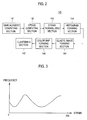
- FIG. 2 is a block diagram showing an illustrative embodiment of the processing unit 140.
- the processing unit 140 may include a displacement computing section 141.
- the displacement computing section 141 may be operable to compute displacements in a pixel unit between first and second frames.
- the displacement computing section 141 may be operable to compute displacement in a block unit (e.g., 4 4, 8 8, etc.).
- the displacements may be computed by using cross-correlation or auto-correlation. However, the computation of the displacements may not be limited thereto.
- the processing unit 140 may further include a strain computing section 142.
- the strain computing section 142 may be operable to compute local strains based on the displacement computed in a pixel unit or a block unit.
- the strains may be computed by one of the well-known strain computation methods. Thus, the detailed descriptions thereof will be omitted herein.
- the processing unit 140 may further include a strain normalizing section 143.
- the strain normalizing section 143 may be operable to normalize the computed strains.
- the strain normalizing section 143 may be operable to detect maximum and minimum strains from the computed strains, and map the strains to values ranging from 0 to 255. In such a case, the minimum strain may be mapped to 0 and the maximum strain may be mapped to 255.
- the strain normalizing section 143 may be operable to compute a mean and standard deviation of the strains.
- the strain normalizing section 143 may be further operable to subtract standard deviation multiplied by 2 from the mean, i.e., perform an operation of (mean - 2 standard deviation), and set the operation result as a minimum value.
- the strain normalizing section 143 may be further operable to add standard deviation multiplied by 2 to the mean, i.e., perform an operation of (mean+2 standard deviation), and set the operation result as a maximum value.
- the strain normalizing section 143 may be operable to map the strains to values ranging from 0 to 255. In such a case, the strains, which are equal to or greater than the maximum value, may be mapped to 255. Further, the strains, which are equal to or less than the minimum value, may be mapped to 0.
- the processing unit 140 may further include a histogram forming section 144.
- the histogram forming section 144 may be operable to form a histogram based on the normalized strains.
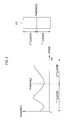
- a horizontal axis may represent a strain and a vertical axis may represent a frequency, as shown in FIG. 3 .
- the processing unit 140 may further include a clustering section 145.
- the clustering section 145 may be operable to cluster the histogram for separation into a plurality of clusters.
- the number of clusters may be selected according to the type of the target object. For example, if the target object may include fats, soft tissues, muscles and bones, then a four number of the clusters may be selected.
- the clustering may be performed by using the Otsu algorithm. If a user input for selecting the number of the clusters (e.g., 2) is inputted through the input unit 110, then the clustering section 145 may be operable to find a threshold by clustering the histogram using the Otsu algorithm. The clustering section 145 may be further operable to separate the histogram into two regions, i.e., a first cluster and a second cluster with reference to the threshold, as illustrated in FIG. 4 .
- the clustering section 145 may be operable to find three thresholds by clustering the histogram using the Otsu algorithm twice.
- the clustering section 145 may be further operable to separate the histogram into four regions, i.e., a first cluster, a second cluster, a third cluster and a fourth cluster with reference to the three thresholds, as illustrated in FIG. 5 .
- the thresholds may be found by using the k-means clustering algorithm.
- the Otsu algorithm and the k-means clustering algorithm may be adopted to cluster the histogram
- the algorithms for clustering are certainly not limited thereto. Any algorithms capable of performing the clustering may be adopted.
- the processing unit 140 may further include a color map forming section 146.
- the color map forming section 146 may be operable to form a color map 210 that maps the strains to colors, as shown in FIG. 4 .
- the color map 210 may be divided into a plurality of color map regions according to the threshold found by the clustering section 145. That is, the number of color map regions may be determined to be equal to the number of clusters.
- colors at each of the color map regions may be independently mapped to the strains. For example, when there are first and second clusters, the color map 210 may be divided into a first color map region and a second color map region.
- the color mapping in the first color map region may be carried out based on the strains included in the first cluster, while the color mapping in the second color map region may be carried out based on the strains included in the second cluster.
- the color map forming section 146 may be operable to form a color map consisting of four color map regions, as shown in FIG. 5 .
- the color mapping is certainly not limited thereto.
- an identical color may be mapped to the color map regions, and brightness thereof may be differently adjusted for each of the color map regions.
- the color at each of the color map regions may be mapped such that a region close to the threshold becomes dark and a region far to the threshold becomes light.
- the processing unit 140 may further comprise an elastic image forming section 147.
- the elastic image forming section 147 may be operable to form an elastic image of the target object based on the strains computed by the strain computing section 142 and the color map formed by the color map forming section 146. Also, the elastic image forming section 147 may be operable to form an elastic image of the target object based on the strains normalized in the strain normalizing section 143.
Landscapes
- Health & Medical Sciences (AREA)
- Life Sciences & Earth Sciences (AREA)
- Engineering & Computer Science (AREA)
- Physics & Mathematics (AREA)
- Medical Informatics (AREA)
- Animal Behavior & Ethology (AREA)
- Radiology & Medical Imaging (AREA)
- Nuclear Medicine, Radiotherapy & Molecular Imaging (AREA)
- Biomedical Technology (AREA)
- Heart & Thoracic Surgery (AREA)
- Biophysics (AREA)
- Molecular Biology (AREA)
- Surgery (AREA)
- Pathology (AREA)
- General Health & Medical Sciences (AREA)
- Public Health (AREA)
- Veterinary Medicine (AREA)
- Computer Networks & Wireless Communication (AREA)
- General Physics & Mathematics (AREA)
- Radar, Positioning & Navigation (AREA)
- Remote Sensing (AREA)
- Ultra Sonic Daignosis Equipment (AREA)
Abstract
Embodiments for forming a color map necessary for forming an elastic image in an ultrasound system. A transmission/reception (Tx/Rx) unit transmits ultrasound signals to a target object and receives ultrasound echo signals reflected from the target object to thereby obtain receive signals. The receive signals include first receive signals obtained before applying a stress to the target object and second receive signals obtained after applying a stress to the target object. An ultrasound data forming unit forms first and second ultrasound data based on the first and second receive signals, respectively. A processing unit computes strains by using the first and second ultrasound data and form a histogram based on the computed strains. The processing unit further clusters the histogram for separation into a plurality of clusters and forms a color map including a plurality of color map regions corresponding to the respective clusters.
Description
- The present application claims priority from Korean Patent Application No.
10-2008-0076342 filed on August 5, 2008 - The present disclosure generally relates to ultrasound systems, and more particularly to the formation of a color map for forming an elastic image in an ultrasound system.
- An ultrasound system has become an important and popular diagnostic tool since it has a wide range of applications. Specifically, due to its non-invasive and non-destructive nature, the ultrasound system has been extensively used in the medical profession. Modem high-performance ultrasound systems and techniques are commonly used to produce two or three-dimensional images of internal features of an object (e.g., human organs).
- Generally, the ultrasound image is displayed in a Brightness-mode (B-mode) by using reflectivity caused by an acoustic impedance difference between the tissues of the target object. However, if the reflectivity of the target object is hardly different from those of the neighboring tissues such as tumor, cancer or the like, then it is not easy to recognize the target object in the B-mode image.
- To resolve the problem of recognizing the tumor, cancer and the like in the B-mode, an ultrasound elastic imaging technology has been developed to visualize mechanical characteristics of the tissues such as the elasticity thereof in the ultrasound system. Such technology is very helpful for diagnosing lesions such as tumor and cancer, which are hardly recognized in the B-mode image. The ultrasound elastic imaging technology may utilize the scientific property that the elasticity of the tissues is related to a pathological phenomenon. For example, the tumor or cancer is relatively stiffer than the neighboring normal tissues. Thus, when stress is uniformly applied, a displacement of the tumor or cancer is typically smaller than those of the neighboring tissues. In order to form an elastic image, strains representing deformation of the tissues due to the application of the stress should be measured. The strains may be measured by using two ultrasound data obtained before and after compressing the tissues.
- Further, the ultrasound system may provide a color map, which maps strains to pseudo colors. The elastic image may be colored according to the color map so that the tissues in the elastic image may be distinguished from each other. The conventional ultrasound system may provide a color map, which is formed by previously set colors, regardless of a portion subject to examination that is formed as an elastic image. For example, the conventional color map may be formed to map relatively large strains to a red color and relatively small strains to a black color. Thus, when the target object may include bones, fats, soft tissues and cancer tissues, a relatively soft portion, such as fats and soft tissues, may be mapped to the red color and a relatively hard portion, such as bones and cancer tissues, may be mapped to the black color. Thus, it may be difficult to separate boundaries and positions between the tissues.
- Embodiments for forming a color map of an elastic image in an ultrasound system are disclosed herein. In one embodiment, by way of non-limiting example, an ultrasound system comprises: a transmission/reception (Tx/Rx) unit operable to transmit ultrasound signals to a target object and receive ultrasound echo signals reflected from the target object to thereby obtain receive signals, the receive signals including first receive signals obtained before applying a stress to the target object and second receive signals obtained after applying a stress to the target object; an ultrasound data forming unit operable to form first and second ultrasound data based on the first and second receive signals, respectively; and a processing unit operable to compute strains by using the first and second ultrasound data and form a histogram of the computed strains, the processing unit being further operable to cluster the histogram for separation into a plurality of clusters and form a color map including a plurality of color map regions corresponding to the respective clusters.
- In another embodiment, a method of forming a color map for an elastic image in an ultrasound system, comprises: a) transmitting ultrasound signals to a target object and receiving ultrasound echo signals reflected from the target object to thereby obtain receive signals, the receive signals including first receive signals obtained before applying a stress to the target object and second receive signals obtained after applying a stress to the target object; b) forming first and second ultrasound data based on the first and second receive signals, respectively; c) computing strains by using the first and second ultrasound data; d) forming a histogram of the computed strains; e) clustering the histogram for separation into a plurality of clusters; and f) forming a color map including a plurality of color map regions corresponding to the respective clusters.
- The Summary is provided to introduce a selection of concepts in a simplified form that are further described below in the Detailed Description. This Summary is not intended to identify key or essential features of the claimed subject matter, nor is it intended to be used in determining the scope of the claimed subject matter.
-
- FIG. 1
- is a block diagram showing an illustrative embodiment of an ultrasound system.
- FIG. 2
- is a block diagram showing an illustrative embodiment of the processing unit shown in
FIG. 1 . - FIG 3
- is a schematic diagram showing an illustrative embodiment of a histogram of normalized strains.
- FIGS. 4 and 5
- are schematic diagrams showing examples of thresholds and clusters obtained through clustering and color maps formed based thereon.
- A detailed description may be provided with reference to the accompanying drawings. One of ordinary skill in the art may realize that the following description is illustrative only and is not in any way limiting. Other embodiments of the present invention may readily suggest themselves to such skilled persons having the benefit of this disclosure.
-
FIG. 1 is a block diagram showing an illustrative embodiment of anultrasound system 100. Referring toFIG. 1 , theultrasound system 100 may include aninput unit 110 that may be operable to receive user inputs. In one embodiment, theinput unit 100 may include a control panel, a mouse and a keyboard. However, it is certainly not limited thereto. - The
ultrasound system 100 may further include a transmission/reception (Tx/Rx)unit 120 that may be operable to transmit ultrasound signals to the target object and receive ultrasound echo signals reflected from the target object to thereby form receive signals. In one embodiment, the Tx/Rx unit 120 may include a transmission (Tx)pulse generator 121, anultrasound probe 122 and a beam former 123. - The
Tx pulse generator 121 may be operable to generate Tx pulses. In one embodiment, a Tx pattern of the Tx pulses may be formed for a B-mode image. Theultrasound probe 122 may include at least one transducer element for reciprocal conversion between electrical signals and ultrasound signals. Theultrasound probe 122 may be operable to receive the Tx pulses and transmit ultrasound signals into the target object in response thereto. Theultrasound probe 122 may be further operable to receive ultrasound echo signals reflected from the target object and convert them into electrical receive signals. The electrical receive signals may be analog signals. In one embodiment, a stress may be applied to the target object by using the probe. The probe may include a compression plate at a front side for compression. The electrical receive signals may include first receive signals obtained before applying a stress to the target object and second receive signals obtained after applying a stress to the target object. - The beam former 123 may be operable to convert the electrical receive signals into digital receive signals and apply delays to the digital receive signals in consideration of distances between the transducer elements and focal points. The beam former 123 may be further operable to sum the digital receive signals with the delays applied, thereby outputting receive-focused digital signals. The receive-focused digital signals may include first digital signals corresponding to the first receive signals and second digital signals corresponding to the second receive signals.
- The
ultrasound system 100 may further include an ultrasounddata forming unit 130. The ultrasounddata forming unit 130 may be embodied by a digital signal processor. The ultrasounddata forming unit 130 may receive the first and second digital signals from the Tx/Rx unit 120 and perform signal processing thereupon such as gain adjustment, time gain compensation and the like, thereby forming ultrasound data. In one embodiment, the ultrasounddata forming unit 130 may be operable to form first ultrasound data corresponding to a first frame based on the first digital signals. Also, the ultrasounddata forming unit 130 may be further operable to form second ultrasound data corresponding to a second frame based on the second digital signals. - The
ultrasound system 100 may further include aprocessing unit 140. Theprocessing unit 140 may be operable to compute strains by comparing the first and second ultrasound data. Theprocessing unit 140 may be further operable to form a color map based on the computed strains. Theprocessing unit 140 may be further operable to form an elastic image based on the computed strains and the color map. - The
ultrasound system 100 may further include adisplay unit 150. Thedisplay unit 150 may display the color map formed in theprocessing unit 140. Also, thedisplay unit 150 may further display the elastic image formed in the elasticimage forming section 147 of theprocessing unit 140. - The
ultrasound system 100 may further include acontrol unit 160 that may be operable to control thedisplay unit 150 to display the elastic image and the color map. Also, thecontrol unit 160 may be operable to control entire operations of theultrasound system 100. -
FIG. 2 is a block diagram showing an illustrative embodiment of theprocessing unit 140. Referring toFIG. 2 , theprocessing unit 140 may include adisplacement computing section 141. Thedisplacement computing section 141 may be operable to compute displacements in a pixel unit between first and second frames. Also, thedisplacement computing section 141 may be operable to compute displacement in a block unit (e.g., 4 4, 8 8, etc.). In one embodiment, the displacements may be computed by using cross-correlation or auto-correlation. However, the computation of the displacements may not be limited thereto. - The
processing unit 140 may further include astrain computing section 142. Thestrain computing section 142 may be operable to compute local strains based on the displacement computed in a pixel unit or a block unit. The strains may be computed by one of the well-known strain computation methods. Thus, the detailed descriptions thereof will be omitted herein. - The
processing unit 140 may further include astrain normalizing section 143. Thestrain normalizing section 143 may be operable to normalize the computed strains. In one embodiment, thestrain normalizing section 143 may be operable to detect maximum and minimum strains from the computed strains, and map the strains to values ranging from 0 to 255. In such a case, the minimum strain may be mapped to 0 and the maximum strain may be mapped to 255. - In one embodiment, the
strain normalizing section 143 may be operable to compute a mean and standard deviation of the strains. Thestrain normalizing section 143 may be further operable to subtract standard deviation multiplied by 2 from the mean, i.e., perform an operation of (mean - 2 standard deviation), and set the operation result as a minimum value. Thestrain normalizing section 143 may be further operable to add standard deviation multiplied by 2 to the mean, i.e., perform an operation of (mean+2 standard deviation), and set the operation result as a maximum value. Thestrain normalizing section 143 may be operable to map the strains to values ranging from 0 to 255. In such a case, the strains, which are equal to or greater than the maximum value, may be mapped to 255. Further, the strains, which are equal to or less than the minimum value, may be mapped to 0. - The
processing unit 140 may further include ahistogram forming section 144. Thehistogram forming section 144 may be operable to form a histogram based on the normalized strains. In the histogram, a horizontal axis may represent a strain and a vertical axis may represent a frequency, as shown inFIG. 3 . - The
processing unit 140 may further include aclustering section 145. Theclustering section 145 may be operable to cluster the histogram for separation into a plurality of clusters. The number of clusters may be selected according to the type of the target object. For example, if the target object may include fats, soft tissues, muscles and bones, then a four number of the clusters may be selected. - In one embodiment, the clustering may be performed by using the Otsu algorithm. If a user input for selecting the number of the clusters (e.g., 2) is inputted through the
input unit 110, then theclustering section 145 may be operable to find a threshold by clustering the histogram using the Otsu algorithm. Theclustering section 145 may be further operable to separate the histogram into two regions, i.e., a first cluster and a second cluster with reference to the threshold, as illustrated inFIG. 4 . Further, if a user input for determining the number of the clusters (e.g., 4) is inputted through theinput unit 110, then theclustering section 145 may be operable to find three thresholds by clustering the histogram using the Otsu algorithm twice. Theclustering section 145 may be further operable to separate the histogram into four regions, i.e., a first cluster, a second cluster, a third cluster and a fourth cluster with reference to the three thresholds, as illustrated inFIG. 5 . In another embodiment, the thresholds may be found by using the k-means clustering algorithm. - Although it is described above that the Otsu algorithm and the k-means clustering algorithm may be adopted to cluster the histogram, the algorithms for clustering are certainly not limited thereto. Any algorithms capable of performing the clustering may be adopted.
- The
processing unit 140 may further include a colormap forming section 146. The colormap forming section 146 may be operable to form acolor map 210 that maps the strains to colors, as shown inFIG. 4 . In one embodiment, thecolor map 210 may be divided into a plurality of color map regions according to the threshold found by theclustering section 145. That is, the number of color map regions may be determined to be equal to the number of clusters. In one embodiment, colors at each of the color map regions may be independently mapped to the strains. For example, when there are first and second clusters, thecolor map 210 may be divided into a first color map region and a second color map region. In such a case, the color mapping in the first color map region may be carried out based on the strains included in the first cluster, while the color mapping in the second color map region may be carried out based on the strains included in the second cluster. Also, when there are four clusters, the colormap forming section 146 may be operable to form a color map consisting of four color map regions, as shown inFIG. 5 . - Although it is described above that the colors are differently mapped at each of the color map regions, the color mapping is certainly not limited thereto. In another embodiment, an identical color may be mapped to the color map regions, and brightness thereof may be differently adjusted for each of the color map regions. Also, the color at each of the color map regions may be mapped such that a region close to the threshold becomes dark and a region far to the threshold becomes light.
- The
processing unit 140 may further comprise an elasticimage forming section 147. In one embodiment, the elasticimage forming section 147 may be operable to form an elastic image of the target object based on the strains computed by thestrain computing section 142 and the color map formed by the colormap forming section 146. Also, the elasticimage forming section 147 may be operable to form an elastic image of the target object based on the strains normalized in thestrain normalizing section 143. - Although embodiments have been described with reference to a number of illustrative embodiments thereof, it should be understood that numerous other modifications and embodiments can be devised by those skilled in the art that will fall within the spirit and scope of the principles of this disclosure. More particularly, numerous variations and modifications are possible in the component parts and/or arrangements of the subject combination arrangement within the scope of the disclosure, the drawings and the appended claims. In addition to variations and modifications in the component parts and/or arrangements, alternative uses will also be apparent to those skilled in the art.
Claims (14)
- An ultrasound system, comprising:a transmission/reception (Tx/Rx) unit operable to transmit ultrasound signals to a target object and receive ultrasound echo signals reflected from the target object to thereby obtain receive signals, the receive signals including first receive signals obtained before applying a stress to the target object and second receive signals obtained after applying a stress to the target object;an ultrasound data forming unit operable to form first and second ultrasound data based on the first and second receive signals, respectively; anda processing unit operable to compute strains by using the first and second ultrasound data and form a histogram of the computed strains, the processing unit being further operable to cluster the histogram for separation into a plurality of clusters and form a color map including a plurality of color map regions corresponding to the respective clusters.
- The ultrasound system of Claim 1, wherein the processing unit includes:a displacement computing section operable to compute displacements by comparing the first and second ultrasound data;a strain computing section operable to compute the strains based on the computed displacements;a strain normalizing section operable to normalize the strains;a histogram forming section operable to form the histogram of the normalized strains;a clustering section operable to cluster the histogram to separate the histogram into the plurality of clusters; anda color map forming section operable to form the color map including the plurality of color map regions corresponding to the respective clusters.
- The ultrasound system of Claim 2, wherein the color map regions are mapped to different colors.
- The ultrasound system of Claim 2, wherein the color map regions are mapped to a color having different brightness from each other.
- The ultrasound system of Claim 2, wherein the strain normalizing section is further operable to:detect maximum and minimum strains from the strains computed by the strain computing section; andmap the strains to values ranging from 0 to 255, wherein the minimum strain is mapped to 0 and the maximum strain is mapped to 255.
- The ultrasound system of Claim 2, wherein the strain normalizing section is further operable to:compute mean and standard deviation of the strains computed by the strain computing section;perform an operation of (mean - 2 standard deviation) to set the operation result as a minimum value;perform an operation of (mean+2 standard deviation) to set the operation result as a maximum value; andmap the strains to values ranging from the maximum value of 0 to the maximum value of 255.
- The ultrasound system of Claim 2, wherein the clustering section is further configured to cluster the histogram to find at least one threshold and separate the histogram into the plurality of clusters based on the threshold.
- A method of forming a color map for an elastic image in an ultrasound system, comprising:a) transmitting ultrasound signals to a target object and receiving ultrasound echo signals reflected from the target object to thereby obtain receive signals, the receive signals including first receive signals obtained before applying a stress to the target object and second receive signals obtained after applying a stress to the target object;b) forming first and second ultrasound data based on the first and second receive signals, respectively;c) compute strains by using the first and second ultrasound data;d) forming a histogram of the computed strains;e) clustering the histogram for separation into a plurality of clusters; andf) forming a color map including a plurality of color map regions corresponding to the respective clusters.
- The method of Claim 8, wherein the c) includes:c1) computing displacements by comparing the first and second ultrasound data;c2) computing the strains based on the computed displacements;c3) normalizing the strains;c4) forming the histogram of the normalized strains;c5) clustering the histogram to separate the histogram into the plurality of clusters; andc6) forming the color map including the plurality of color map regions corresponding to the respective clusters.
- The method of Claim 9, wherein the color map regions are mapped to different colors.
- The method of Claim 9, wherein the color map regions are mapped to a color having different brightness from each other.
- The method of Claim 9, wherein the c3 includes:detecting maximum and minimum strains from the strains; andmapping the strains to values ranging from 0 to 255, wherein the minimum strain is mapped to 0 and the maximum strain is mapped to 255.
- The method of Claim 9, wherein the c3) includes:computing mean and standard deviation of the strains;performing an operation of (mean - 2 standard deviation) to set the operation result as a minimum value;performing an operation of (mean+2 standard deviation) to set the operation result as a maximum value; andmapping the strains to values ranging from 0 to 255 with reference to the maximum and minimum values.
- The method of Claim 9, wherein the c5) includes clustering the histogram to find at least one threshold, and separating the histogram into the plurality of clusters based on the threshold.
Applications Claiming Priority (1)
| Application Number | Priority Date | Filing Date | Title |
|---|---|---|---|
| KR1020080076342A KR101100498B1 (en) | 2008-08-05 | 2008-08-05 | Ultrasound System and Method for Forming Color Map |
Publications (1)
| Publication Number | Publication Date |
|---|---|
| EP2151195A1 true EP2151195A1 (en) | 2010-02-10 |
Family
ID=41037745
Family Applications (1)
| Application Number | Title | Priority Date | Filing Date |
|---|---|---|---|
| EP09166289A Withdrawn EP2151195A1 (en) | 2008-08-05 | 2009-07-24 | Formation of a color map for an elastic image |
Country Status (4)
| Country | Link |
|---|---|
| US (1) | US9629605B2 (en) |
| EP (1) | EP2151195A1 (en) |
| JP (1) | JP2010036041A (en) |
| KR (1) | KR101100498B1 (en) |
Cited By (2)
| Publication number | Priority date | Publication date | Assignee | Title |
|---|---|---|---|---|
| CN107427284A (en) * | 2015-10-23 | 2017-12-01 | 奥林巴斯株式会社 | The working procedure of ultrasound observation apparatus, the method for work of ultrasound observation apparatus and ultrasound observation apparatus |
| CN107884035A (en) * | 2016-09-30 | 2018-04-06 | 罗斯蒙特储罐雷达股份公司 | Radar level gauge system and the method for determining the interface material position in storage tank |
Families Citing this family (8)
| Publication number | Priority date | Publication date | Assignee | Title |
|---|---|---|---|---|
| JP2013542046A (en) * | 2010-11-10 | 2013-11-21 | エコーメトリックス,エルエルシー | Ultrasound image processing system and method |
| US9629610B2 (en) | 2010-12-22 | 2017-04-25 | Samsung Medison Co., Ltd. | Method of operating ultrasound diagnosis apparatus for providing map of interest index and ultrasound diagnosis apparatus using the method |
| US20120165665A1 (en) * | 2010-12-22 | 2012-06-28 | Samsung Medison Co., Ltd. | Method for providing mechanical index map and/or pressure map based on depth value and diagnostic ultrasound system using the method |
| JP5774560B2 (en) * | 2012-08-20 | 2015-09-09 | ジーイー・メディカル・システムズ・グローバル・テクノロジー・カンパニー・エルエルシー | Ultrasonic diagnostic apparatus and control program therefor |
| KR20150069830A (en) * | 2013-12-16 | 2015-06-24 | 삼성전자주식회사 | Method for providing blood vessel analysis information using medical image and apparatus providing blood vessel analysis information using medical image |
| WO2021002122A1 (en) * | 2019-07-03 | 2021-01-07 | パナソニックIpマネジメント株式会社 | Stress distribution image processing device |
| KR102414647B1 (en) * | 2020-11-02 | 2022-06-30 | 주식회사 맵퍼스 | System and method for extracting lane data using mobile mapping system |
| CN113397600A (en) * | 2021-06-18 | 2021-09-17 | 复旦大学 | Hepatic fibrosis assessment method based on ultrasonic radio frequency signal elastic reconstruction |
Citations (4)
| Publication number | Priority date | Publication date | Assignee | Title |
|---|---|---|---|---|
| EP0772158A2 (en) * | 1995-10-30 | 1997-05-07 | Hewlett-Packard Company | Image processing system |
| EP1810620A1 (en) * | 2006-01-24 | 2007-07-25 | Medison Co., Ltd. | Ultrasound diagnostic system and method of forming elastic images |
| US20070242863A1 (en) * | 2006-04-13 | 2007-10-18 | Bernice Eland Hoppel | Methods and Apparatus for Contouring at Least One Vessel |
| EP1938754A1 (en) * | 2005-10-19 | 2008-07-02 | Hitachi Medical Corporation | Ultrasonograph for creating elastic image |
Family Cites Families (20)
| Publication number | Priority date | Publication date | Assignee | Title |
|---|---|---|---|---|
| US7245746B2 (en) * | 2001-06-12 | 2007-07-17 | Ge Medical Systems Global Technology Company, Llc | Ultrasound color characteristic mapping |
| JP2003102723A (en) | 2001-09-27 | 2003-04-08 | Ge Medical Systems Global Technology Co Llc | Medical image display device and control method therefor |
| US6638228B1 (en) * | 2002-04-26 | 2003-10-28 | Koninklijke Philips Electronics N.V. | Contrast-agent enhanced color-flow imaging |
| US20040067591A1 (en) * | 2002-10-04 | 2004-04-08 | Wisconsin Alumni Research Foundation | Tissue mimicking elastography phantoms |
| JP4314035B2 (en) | 2003-01-15 | 2009-08-12 | 株式会社日立メディコ | Ultrasonic diagnostic equipment |
| US20050065429A1 (en) * | 2003-09-18 | 2005-03-24 | Ge Medical Systems Global Technology Company, Llc | Method for three plane interleaved acquisition for three dimensional temperature monitoring with MRI |
| AU2004203059A1 (en) * | 2004-06-08 | 2005-12-22 | The Government Of The United States Of America As Represented By The Secretary Of The Department Of Health And Human Services, Centers For Disease Control And Prevention | Apparatus and method for assessing peripheral circulation to evaluate a physiological condition |
| EP1647837B1 (en) | 2004-10-15 | 2008-08-13 | Medison Co., Ltd. | Ultrasound diagnostic system for providing elastic image with additional information |
| US20060084125A1 (en) * | 2004-10-18 | 2006-04-20 | Herzel Laor | Methods, devices, and systems for detection of cancer |
| US7736313B2 (en) * | 2004-11-22 | 2010-06-15 | Carestream Health, Inc. | Detecting and classifying lesions in ultrasound images |
| JP4874810B2 (en) * | 2004-11-26 | 2012-02-15 | 株式会社東芝 | X-ray CT system |
| CN100544678C (en) * | 2005-05-09 | 2009-09-30 | 株式会社日立医药 | Ultrasonic diagnostic device |
| KR100847796B1 (en) | 2005-07-27 | 2008-07-23 | 주식회사 메디슨 | Ultrasound system for forming and displaying elastic image |
| EP1747757B8 (en) * | 2005-07-27 | 2012-02-29 | Samsung Medison Co., Ltd. | Ultrasound system for displaying an elastic image |
| US8838215B2 (en) * | 2006-03-01 | 2014-09-16 | Angel Medical Systems, Inc. | Systems and methods of medical monitoring according to patient state |
| US7678051B2 (en) * | 2005-09-27 | 2010-03-16 | Siemens Medical Solutions Usa, Inc. | Panoramic elasticity ultrasound imaging |
| US20070263915A1 (en) * | 2006-01-10 | 2007-11-15 | Adi Mashiach | System and method for segmenting structures in a series of images |
| KR100908248B1 (en) * | 2006-09-13 | 2009-07-20 | 주식회사 메디슨 | Elastic video display method |
| JP4026158B1 (en) | 2006-09-27 | 2007-12-26 | 国立大学法人岐阜大学 | Interpretation support device, interpretation support method and program |
| JP2008161674A (en) | 2006-12-04 | 2008-07-17 | Matsushita Electric Ind Co Ltd | Ultrasonic diagnostic equipment |
-
2008
- 2008-08-05 KR KR1020080076342A patent/KR101100498B1/en not_active Expired - Fee Related
-
2009
- 2009-07-24 EP EP09166289A patent/EP2151195A1/en not_active Withdrawn
- 2009-08-04 US US12/535,604 patent/US9629605B2/en not_active Expired - Fee Related
- 2009-08-05 JP JP2009182325A patent/JP2010036041A/en active Pending
Patent Citations (4)
| Publication number | Priority date | Publication date | Assignee | Title |
|---|---|---|---|---|
| EP0772158A2 (en) * | 1995-10-30 | 1997-05-07 | Hewlett-Packard Company | Image processing system |
| EP1938754A1 (en) * | 2005-10-19 | 2008-07-02 | Hitachi Medical Corporation | Ultrasonograph for creating elastic image |
| EP1810620A1 (en) * | 2006-01-24 | 2007-07-25 | Medison Co., Ltd. | Ultrasound diagnostic system and method of forming elastic images |
| US20070242863A1 (en) * | 2006-04-13 | 2007-10-18 | Bernice Eland Hoppel | Methods and Apparatus for Contouring at Least One Vessel |
Non-Patent Citations (1)
| Title |
|---|
| ARIFIN A Z ET AL: "Image segmentation by histogram thresholding using hierarchical cluster analysis", PATTERN RECOGNITION LETTERS, ELSEVIER, AMSTERDAM, NL, vol. 27, no. 13, 1 October 2006 (2006-10-01), pages 1515 - 1521, XP025053195, ISSN: 0167-8655, [retrieved on 20061001] * |
Cited By (3)
| Publication number | Priority date | Publication date | Assignee | Title |
|---|---|---|---|---|
| CN107427284A (en) * | 2015-10-23 | 2017-12-01 | 奥林巴斯株式会社 | The working procedure of ultrasound observation apparatus, the method for work of ultrasound observation apparatus and ultrasound observation apparatus |
| CN107427284B (en) * | 2015-10-23 | 2021-04-13 | 奥林巴斯株式会社 | Ultrasonic observation device, working method of ultrasonic observation device, and storage medium |
| CN107884035A (en) * | 2016-09-30 | 2018-04-06 | 罗斯蒙特储罐雷达股份公司 | Radar level gauge system and the method for determining the interface material position in storage tank |
Also Published As
| Publication number | Publication date |
|---|---|
| US20100036250A1 (en) | 2010-02-11 |
| KR20100016740A (en) | 2010-02-16 |
| KR101100498B1 (en) | 2011-12-29 |
| JP2010036041A (en) | 2010-02-18 |
| US9629605B2 (en) | 2017-04-25 |
Similar Documents
| Publication | Publication Date | Title |
|---|---|---|
| US9629605B2 (en) | Formation of a color map for an elastic image | |
| US8684934B2 (en) | Adaptively performing clutter filtering in an ultrasound system | |
| US9008383B2 (en) | Enhancing quality of ultrasound image in ultrasound system | |
| US7833159B2 (en) | Image processing system and method of enhancing the quality of an ultrasound image | |
| US8900147B2 (en) | Performing image process and size measurement upon a three-dimensional ultrasound image in an ultrasound system | |
| US8956298B2 (en) | Providing an ultrasound spatial compound image in an ultrasound system | |
| US8469888B2 (en) | Formation of an enhanced elastic image in an ultrasound system | |
| EP2290395A2 (en) | Ultrasound system and method for providing information indicative of a change of elasticity information | |
| JPWO2005087111A1 (en) | Medical image diagnostic apparatus and medical image diagnostic method | |
| US9149256B2 (en) | Ultrasound strain imaging based on lateral displacement compensation | |
| US20120108962A1 (en) | Providing a body mark in an ultrasound system | |
| US20100016722A1 (en) | Formation of an elastic image in an ultrasound system | |
| EP2157442A1 (en) | Formation of an elastic image in an ultrasound system | |
| US20110028842A1 (en) | Providing A Plurality Of Slice Images In An Ultrasound System | |
| US20120053463A1 (en) | Providing ultrasound spatial compound images in an ultrasound system | |
| US20100152585A1 (en) | Ultrasound System And Method For Forming A Plurality Of Three-Dimensional Ultrasound Images | |
| US9125618B2 (en) | Providing an elastic image in an ultrasound system | |
| US9289190B2 (en) | Ultrasound strain imaging via pixel frame and window correlation | |
| US8337406B2 (en) | Adaptive persistence processing of elastic images | |
| KR102005326B1 (en) | Method for acquiring 3d depth information in image and system therefor | |
| EP2238911B1 (en) | Providing stress information in an ultrasound system | |
| US20100130862A1 (en) | Providing Volume Information On A Periodically Moving Target Object In An Ultrasound System | |
| US8503714B2 (en) | Dropout correction in ultrasound strain imaging | |
| US20120083694A1 (en) | Stretching based strain imaging in an ultrasound system |
Legal Events
| Date | Code | Title | Description |
|---|---|---|---|
| PUAI | Public reference made under article 153(3) epc to a published international application that has entered the european phase |
Free format text: ORIGINAL CODE: 0009012 |
|
| AK | Designated contracting states |
Kind code of ref document: A1 Designated state(s): AT BE BG CH CY CZ DE DK EE ES FI FR GB GR HR HU IE IS IT LI LT LU LV MC MK MT NL NO PL PT RO SE SI SK SM TR |
|
| 17P | Request for examination filed |
Effective date: 20100609 |
|
| 17Q | First examination report despatched |
Effective date: 20100716 |
|
| 18D | Application deemed to be withdrawn |
Effective date: 20150202 |
|
| STAA | Information on the status of an ep patent application or granted ep patent |
Free format text: STATUS: THE APPLICATION IS DEEMED TO BE WITHDRAWN |
|
| R18D | Application deemed to be withdrawn (corrected) |
Effective date: 20150203 |