EP2150809B1 - Device for the distribution of sample and carrier liquid across a micro-fabricated separation channel - Google Patents
Device for the distribution of sample and carrier liquid across a micro-fabricated separation channel Download PDFInfo
- Publication number
- EP2150809B1 EP2150809B1 EP08759970.0A EP08759970A EP2150809B1 EP 2150809 B1 EP2150809 B1 EP 2150809B1 EP 08759970 A EP08759970 A EP 08759970A EP 2150809 B1 EP2150809 B1 EP 2150809B1
- Authority
- EP
- European Patent Office
- Prior art keywords
- pillars
- micro
- flow distribution
- fabricated
- separation channel
- Prior art date
- Legal status (The legal status is an assumption and is not a legal conclusion. Google has not performed a legal analysis and makes no representation as to the accuracy of the status listed.)
- Active
Links
Images



Classifications
-
- G—PHYSICS
- G01—MEASURING; TESTING
- G01N—INVESTIGATING OR ANALYSING MATERIALS BY DETERMINING THEIR CHEMICAL OR PHYSICAL PROPERTIES
- G01N30/00—Investigating or analysing materials by separation into components using adsorption, absorption or similar phenomena or using ion-exchange, e.g. chromatography or field flow fractionation
- G01N30/02—Column chromatography
- G01N30/60—Construction of the column
- G01N30/6095—Micromachined or nanomachined, e.g. micro- or nanosize
-
- B—PERFORMING OPERATIONS; TRANSPORTING
- B01—PHYSICAL OR CHEMICAL PROCESSES OR APPARATUS IN GENERAL
- B01L—CHEMICAL OR PHYSICAL LABORATORY APPARATUS FOR GENERAL USE
- B01L3/00—Containers or dishes for laboratory use, e.g. laboratory glassware; Droppers
- B01L3/50—Containers for the purpose of retaining a material to be analysed, e.g. test tubes
- B01L3/502—Containers for the purpose of retaining a material to be analysed, e.g. test tubes with fluid transport, e.g. in multi-compartment structures
- B01L3/5027—Containers for the purpose of retaining a material to be analysed, e.g. test tubes with fluid transport, e.g. in multi-compartment structures by integrated microfluidic structures, i.e. dimensions of channels and chambers are such that surface tension forces are important, e.g. lab-on-a-chip
- B01L3/502746—Containers for the purpose of retaining a material to be analysed, e.g. test tubes with fluid transport, e.g. in multi-compartment structures by integrated microfluidic structures, i.e. dimensions of channels and chambers are such that surface tension forces are important, e.g. lab-on-a-chip characterised by the means for controlling flow resistance, e.g. flow controllers, baffles or throttle valves
-
- B—PERFORMING OPERATIONS; TRANSPORTING
- B01—PHYSICAL OR CHEMICAL PROCESSES OR APPARATUS IN GENERAL
- B01L—CHEMICAL OR PHYSICAL LABORATORY APPARATUS FOR GENERAL USE
- B01L3/00—Containers or dishes for laboratory use, e.g. laboratory glassware; Droppers
- B01L3/50—Containers for the purpose of retaining a material to be analysed, e.g. test tubes
- B01L3/502—Containers for the purpose of retaining a material to be analysed, e.g. test tubes with fluid transport, e.g. in multi-compartment structures
- B01L3/5027—Containers for the purpose of retaining a material to be analysed, e.g. test tubes with fluid transport, e.g. in multi-compartment structures by integrated microfluidic structures, i.e. dimensions of channels and chambers are such that surface tension forces are important, e.g. lab-on-a-chip
- B01L3/502753—Containers for the purpose of retaining a material to be analysed, e.g. test tubes with fluid transport, e.g. in multi-compartment structures by integrated microfluidic structures, i.e. dimensions of channels and chambers are such that surface tension forces are important, e.g. lab-on-a-chip characterised by bulk separation arrangements on lab-on-a-chip devices, e.g. for filtration or centrifugation
-
- G—PHYSICS
- G01—MEASURING; TESTING
- G01N—INVESTIGATING OR ANALYSING MATERIALS BY DETERMINING THEIR CHEMICAL OR PHYSICAL PROPERTIES
- G01N30/00—Investigating or analysing materials by separation into components using adsorption, absorption or similar phenomena or using ion-exchange, e.g. chromatography or field flow fractionation
- G01N30/02—Column chromatography
- G01N30/60—Construction of the column
- G01N30/6004—Construction of the column end pieces
- G01N30/6017—Fluid distributors
-
- B—PERFORMING OPERATIONS; TRANSPORTING
- B01—PHYSICAL OR CHEMICAL PROCESSES OR APPARATUS IN GENERAL
- B01L—CHEMICAL OR PHYSICAL LABORATORY APPARATUS FOR GENERAL USE
- B01L2200/00—Solutions for specific problems relating to chemical or physical laboratory apparatus
- B01L2200/06—Fluid handling related problems
- B01L2200/0631—Purification arrangements, e.g. solid phase extraction [SPE]
-
- B—PERFORMING OPERATIONS; TRANSPORTING
- B01—PHYSICAL OR CHEMICAL PROCESSES OR APPARATUS IN GENERAL
- B01L—CHEMICAL OR PHYSICAL LABORATORY APPARATUS FOR GENERAL USE
- B01L2200/00—Solutions for specific problems relating to chemical or physical laboratory apparatus
- B01L2200/12—Specific details about manufacturing devices
-
- B—PERFORMING OPERATIONS; TRANSPORTING
- B01—PHYSICAL OR CHEMICAL PROCESSES OR APPARATUS IN GENERAL
- B01L—CHEMICAL OR PHYSICAL LABORATORY APPARATUS FOR GENERAL USE
- B01L2400/00—Moving or stopping fluids
- B01L2400/04—Moving fluids with specific forces or mechanical means
- B01L2400/0403—Moving fluids with specific forces or mechanical means specific forces
- B01L2400/0406—Moving fluids with specific forces or mechanical means specific forces capillary forces
-
- B—PERFORMING OPERATIONS; TRANSPORTING
- B01—PHYSICAL OR CHEMICAL PROCESSES OR APPARATUS IN GENERAL
- B01L—CHEMICAL OR PHYSICAL LABORATORY APPARATUS FOR GENERAL USE
- B01L2400/00—Moving or stopping fluids
- B01L2400/04—Moving fluids with specific forces or mechanical means
- B01L2400/0403—Moving fluids with specific forces or mechanical means specific forces
- B01L2400/0457—Moving fluids with specific forces or mechanical means specific forces passive flow or gravitation
-
- B—PERFORMING OPERATIONS; TRANSPORTING
- B01—PHYSICAL OR CHEMICAL PROCESSES OR APPARATUS IN GENERAL
- B01L—CHEMICAL OR PHYSICAL LABORATORY APPARATUS FOR GENERAL USE
- B01L2400/00—Moving or stopping fluids
- B01L2400/08—Regulating or influencing the flow resistance
- B01L2400/084—Passive control of flow resistance
- B01L2400/086—Passive control of flow resistance using baffles or other fixed flow obstructions
Definitions
- the present invention relates to the field of liquid chromatography.
- the invention provides a device and method for the distribution of sample and carrier liquid across a separation channel.
- microfabricated separation channels arranged on the surface of a polymer, silicon or glass wafer.
- said microfabricated separation channels usually have a flat-rectangular cross-section, i.e. are much wider than deep or are much deeper than wide.
- microfabricated separation channels are coupled to a sample injector and to a detector device.
- this coupling is ensured using a cylindrical connection capillary.
- the technological challenge surfacing here is that the liquid coming from a round tubing with limited diameter should be spread uniformly over the cross-section of said microfabricated separation channel without creating excessive band broadening or axial dispersion.
- a distribution zone is arranged to make the transition between the flow in the flat-rectangular separation channel and the circular tubing needed to lead the sample towards an off-chip detector. If performing liquid chromatography, this transition should occur with a minimum of band broadening.
- One of the general engineering rules that can be used for the design of these flow distribution structures is that they should have a small total volume, for the band broadening or axial dispersion of a device is generally proportional to its volume.
- the present invention provides a device for the distribution of sample and carrier liquid in a micro-fabricated separation channel, wherein dispersion or permeability of the sample and carrier liquid across said separation channel is improved.
- the invention provides a device in which flow distribution zones are designed, wherein the lateral dispersion or permeability is promoted so as to become larger than the axial dispersion or permeability. Given that the incoming liquid needs to be spread in the lateral direction across the channel cross-section, such design is much more advantageous.
- the flow distribution structures proposed in US patent 6,156,273 and Sant et al. (2006) is that they have a lateral dispersion that is smaller than their axial dispersion.
- a device wherein flow distribution regions are developed that are filled, preferably over their entire depth, with an array of micro-fabricated pillars having a shape, size and positioning pattern selected such that said flow distribution region has a ratio of transversal to axial permeability of at least 2.
- This permeability ratio can for example be calculated using computational fluid dynamics software to calculate the pressure drop of a flow progressing through the distribution region in the axial direction and comparing that with the pressure drop of a flow progressing through the distribution region in the transversal direction with the same mean velocity. The ratio of both pressure drops is then the inverse of the permeability ratio.
- the present invention relates to a flow distribution region designed to spread a liquid uniformly across the lateral width of a flat-rectangular separation channel containing a separation medium.
- Said separation medium can be another micro-pillar array, a bead packing, a monolithic support or any other suitable chromatographic medium.
- distribution and “ dispersion” are used herein in some embodiments as synonyms and refer to the spatial property of being scattered about over an area or volume.
- permeability refers to the rate of flow of a liquid through a material, preferably across a micro-fabricated separation channel as defined herein.
- the invention provides a chromatographic separation device comprising a first substrate body carrying a micro-fabricated separation channel recessed on one of its surfaces and covered by a second substrate body, both perforated with the necessary connection-holes for the supply and withdrawal of the sample and mobile phase liquid, characterized therein that said micro-fabricated separation channel is preceded or succeeded by a flow distribution region that is filled from bottom to top with an array of micro-fabricated pillars having a shape, size and positioning pattern selected such that said flow distribution region has a ratio of transversal to axial permeability of at least 2.
- the invention relates to a chromatographic separation device comprising a first substrate body carrying a micro-fabricated separation channel recessed on one of its surfaces and covered by a second substrate body, whereby said first and said second substrate body are both perforated with inlet and outlet connection-holes for the supply and withdrawal of a sample and carrier liquid, characterized in that said micro-fabricated separation channel is preceded or succeeded by a flow distribution region that is filled with an array of micro-fabricated pillars, whereby said pillars have a shape, size and positioning pattern selected such that said flow distribution region has a ratio of transversal to axial permeability of at least 2.
- said flow distribution region has a substantially uniform lateral width, said width being equal to the width of said separation channel.
- a device wherein said micro-fabricated pillars have a diamond-like or ellipsoidal shape.
- said micro-fabricated pillars have a ratio of lateral width to axial width that is larger than 3/2.
- the invention relates to a device wherein said micro-fabricated pillars are arranged in different zones of different pillar sizes, whereby said different zones are arranged in a substantially monotonic order from the zone containing the smallest pillars to the zone containing the largest pillars, and whereby the zone containing the largest pillars is arranged closest to the inlet or outlet connection hole of said substrate body.
- a device wherein said micro-fabricated pillar zone having the largest pillars is adjacent to an open zone devoid of pillars.
- Said open zone preferably has a width of 1 to 20 ⁇ m.
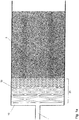
- Fig. 1a shows an embodiment of a flow distribution region according the present invention and preceding a separation channel filled with a separation medium 5, comprising a short open region 10, constituting a flow domain wherein the resistance against the flow in the lateral direction is minimal, preferably 1 to 10 ⁇ m wide and being directly connected to the inlet orifice 1, followed by a flow distribution region 20 according to the present invention comprising micro-machined pillars 30 having a ratio of lateral width 31 to axial width 32 ( Fig. 1b ) that is larger than 3/2 and sufficiently closely packed to induce a lateral permeability that is at least 2 times larger than the axial permeability.
- said micro-machined pillars are arranged in order of decreasing size, with the largest pillars closest to the inlet orifice 1 of the substrate body carrying said separation channel.
- the different regions making up the flow distribution regions should be arranged in an opposite order, starting with the smallest flow distribution pillars and ending with the open region.
- Fig. 1b shows a top view of a number of the possible micro-fabricated pillar shapes that can be effective for use in the flow distribution region(s) according to the present invention.
- micro-fabricated or micro-machined are used herein as synonym. Methods to produce the desired micro-pillars are well-known to those skilled in the art of micromachining, and are for example Bosch etching or LIGA replication. Substrates suitable to produce the micro-pillars are for example glass wafers or silica wafer.
- micro-pillar or "pillar” as used herein refer to structures that have been fabricated using a micromachining technique.
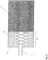
- the invention provides a device wherein the size and the inter-pillar distance of said micro-pillars is varied in lateral direction.
- Such embodiment is for instance illustrated on Fig. 2 .
- At least one part of the flow distribution region has a lesser depth than said separation channel, i.e. it is etched to a lesser depth than said separation channel.
- Fig. 3 shows such an embodiment, wherein the open region 10a and a first part of the flow distribution region 20a is etched to a significantly lesser depth than the separation channel containing the separation medium 5 and the second part of the flow distribution region 20b, preferably also preceded by an open region 10b.
- the advantage of this embodiment is that a further reduction of the volume of the flow distribution region is created.
- said deeper etched second part 20b can be omitted.
- a particular advantage of deeper etched second part 20b of said flow distribution can be obtained by selecting the pillar sizes and inter-pillar dimensions such that the axial permeability of said second part is very low. This will help to induce a convective flow in the open region 10b that runs essentially in the downward direction, hence promoting the mixing across the depth of the separation channel.
- the invention provides a device, wherein at least one part of the flow distribution region is arranged on a different surface than the surface carrying said separation channel.
- the present invention is not limited to flow distribution regions that are arranged on the same surface as the surface carrying said separation channel.
- the use of a perpendicularly etched connection channel 25 allows at least a part of the flow distribution region 20a to be arranged on either the surface of the substrate body 40 carrying the separation channel filled with the separation medium 5 (opposite to the surface carrying the separation channel), or on one of the surfaces of the substrate body 60 used to close off the separation channel.
- the advantage of these embodiments is that the perpendicular running connection channel 25 will induce a perpendicular flow to the separation channel, hence promoting mixing in the depth of the channel.
- a device may be provided wherein at least two different flow distribution regions are present at a different surface and are connected to a different liquid reservoir. Multiple inlet flows coming from different fluid reservoirs can be used. For example, as represented on Fig. 5 , one inlet flow is provided that feeds a first distribution region 20a, and a second inlet flow is provided that feeds a second distribution region 20b, and that enters the separation device via a second inlet orifice 70 machined in a third substrate 80 used to close off the second distribution region 20b ( Fig. 5 ).
- the advantage of this embodiment is that the sample to be separated can be sent through a flow distribution region that is smaller -hence creating less band broadening- than the flow distribution region used for the main mobile phase flow or carrier fluid. Both separate inlet flows can be organized alternately or simultaneously.
- a device wherein said flow distribution region is provided with one or more impermeable thin walls, which at least partly divide said flow distribution regions in two or more sections, said walls being provided parallel with the mean flow direction, and wherein preferably said sections are each connected to a different in- or outlet channel.
- the flow distribution region is at least partly divided using n impermeable thin walls 800, n being larger than 1, running parallel with the mean flow direction and hence preventing the communication between different lateral parts of the flow distribution region.
- Fig. 6a illustrates how this approach can be used to feed the sample to the central part of the channel only, using separate feeding channels 81, 82 and 83.
- FIG. 6b illustrates how this approach can be used to feed the liquid running through the central part of the channel exclusively to the detector device using a first outlet channel 92, while the liquid flowing closest to the channel side walls is evacuated to the waste using a second and a third outlet channel 91 and 93.
- Arranging said flow dividing impermeable walls into the flow distributor region is especially advantageous because the flow distributor will anyhow also limit the band broadening induced by the transition between the broad separation channel and the narrow in- and outlet channels and also because the high flow resistance of the distributor regions according to the present invention allows alleviating the influence of differences in flow resistance among the parallel inlet channels or among the parallel outlet channels by making the flow resistance of said parallel inlet and outlet channels negligible compared to the flow resistance of the flow distributor region.
- the present invention further relates to a method for controlling dispersion and/or permeability of a sample and carrier liquid across a micro-fabricated separation channel having inlet and outlet connection-holes for respectively the supply and the withdrawal of said sample and carrier liquid, said method comprising inducing a lateral permeability that is larger than an axial permeability.
- said method comprises inducing a lateral permeability that is at least 2 times larger than said axial permeability.
- the present method is carried out by providing in the front of, or in the back of said micro-fabricated separation channel a flow distribution region that is filled with an array of micro-fabricated pillars. Said pillars have a shape, size and positioning pattern as defined herein and selected such that said flow distribution region provides a ratio of transversal to axial permeability of at least 2.
- the invention provides a method for controlling flow dispersion or permeability of a sample and carrier liquid across a micro-fabricated separation channel comprising inducing in the lateral parts of said separation channel that are most remote of said connection holes a lower flow resistance.
- This embodiment can be obtained by adapting shape, size, positioning pattern, and/or inter-pillar distance of said micro-pillars in the lateral direction of said micro-fabricated separation channel.
- the invention further provides a method comprising separately controlling the permeability (dispersion) of said sample and said carrier liquid.
- Top view CCD-camera images can be used for comparing the band broadening obtained with a flow distribution region according to the present invention and being composed of diamond pillars with a lateral width that is 10 times larger than the axial width and therefore having a ratio of transversal to axial dispersion larger than two with the band broadening obtained in a continuously bifurcating inlet system as for example disclosed in US patent N° 6,156,273 .
- the band in the device according to the invention is clearly narrower and less distorted than the band in the prior art device.
- the distortions of the latter band are caused by the fact that any band distortion originating from a difference in flow resistance, caused by inevitable small etching errors, between the branches of a bifurcating channel system can not be corrected in the remainder of the inlet system since the different branches of the bifurcating inlet are not transversally interconnected.
- the flow distributors according to the present invention are designed such that they promote lateral mixing and therefore allow the immediate correction, through lateral mixing, of small band distortions.
Landscapes
- Chemical & Material Sciences (AREA)
- Health & Medical Sciences (AREA)
- General Health & Medical Sciences (AREA)
- Analytical Chemistry (AREA)
- Life Sciences & Earth Sciences (AREA)
- Immunology (AREA)
- Biochemistry (AREA)
- General Physics & Mathematics (AREA)
- Physics & Mathematics (AREA)
- Pathology (AREA)
- Dispersion Chemistry (AREA)
- Hematology (AREA)
- Clinical Laboratory Science (AREA)
- Chemical Kinetics & Catalysis (AREA)
- Molecular Biology (AREA)
- Engineering & Computer Science (AREA)
- Nanotechnology (AREA)
- Treatment Of Liquids With Adsorbents In General (AREA)
Description
- The present invention relates to the field of liquid chromatography. The invention provides a device and method for the distribution of sample and carrier liquid across a separation channel.
- In the art of liquid chromatography, more and more devices are being developed that make use of microfabricated separation channels arranged on the surface of a polymer, silicon or glass wafer. Using etching techniques, said microfabricated separation channels usually have a flat-rectangular cross-section, i.e. are much wider than deep or are much deeper than wide.
- To perform and detect a liquid chromatographic separation, said microfabricated separation channels are coupled to a sample injector and to a detector device. Traditionally, this coupling is ensured using a cylindrical connection capillary. The technological challenge surfacing here is that the liquid coming from a round tubing with limited diameter should be spread uniformly over the cross-section of said microfabricated separation channel without creating excessive band broadening or axial dispersion. Similarly, it is also important that at the end of the separation channel a distribution zone is arranged to make the transition between the flow in the flat-rectangular separation channel and the circular tubing needed to lead the sample towards an off-chip detector. If performing liquid chromatography, this transition should occur with a minimum of band broadening. One of the general engineering rules that can be used for the design of these flow distribution structures is that they should have a small total volume, for the band broadening or axial dispersion of a device is generally proportional to its volume.
- With this in mind, a solution to disperse the liquid across a microchannel proposed in Sant el al. (2006, Reduction of End Effect-Induced Zone Broadening in Field-Flow Fractionation Channels, Anal. Chem., online publication A-H), and making use of a triangular distribution region with an opening angle between 60 and 90 degrees, has the clear drawback that it would occupy a too large volume if the ratio of separation channel width to inlet channel width is large. For example, if the separation channel would be 1 cm wide, the length of the distribution triangle in the case of 90 degree opening angle a would also have to be 1 cm. The continuously bifurcating channel inlet proposed in
US patent N° 6,156,273 also makes use of such a diverging channel inlet or outlet. - There is a need in the art for providing a device for the distribution of sample and carrier liquid across a micro-fabricated separation channel, which overcomes at least some of the above-indicated drawbacks.
- The present invention provides a device for the distribution of sample and carrier liquid in a micro-fabricated separation channel, wherein dispersion or permeability of the sample and carrier liquid across said separation channel is improved. In particular, the invention provides a device in which flow distribution zones are designed, wherein the lateral dispersion or permeability is promoted so as to become larger than the axial dispersion or permeability. Given that the incoming liquid needs to be spread in the lateral direction across the channel cross-section, such design is much more advantageous. It is noted that the flow distribution structures proposed in
US patent 6,156,273 and Sant et al. (2006) is that they have a lateral dispersion that is smaller than their axial dispersion. - Thereto, in all embodiments according to the present invention, a device is provided wherein flow distribution regions are developed that are filled, preferably over their entire depth, with an array of micro-fabricated pillars having a shape, size and positioning pattern selected such that said flow distribution region has a ratio of transversal to axial permeability of at least 2.
- This permeability ratio can for example be calculated using computational fluid dynamics software to calculate the pressure drop of a flow progressing through the distribution region in the axial direction and comparing that with the pressure drop of a flow progressing through the distribution region in the transversal direction with the same mean velocity. The ratio of both pressure drops is then the inverse of the permeability ratio.
- A mathematical definition of permeability is given in Eq. (7) of De Smet J. et al. :"Influence of the Pillar Shape on the Band Broadening and the Separation Impedance of Perfectly Ordered 2-D Porous Chromatographic Media" Analytical chemistry, 76(3), 2004.
- Eghbali H. et al.: "Pressure-driven Chromatography in Perfectly Ordered Pillar Array Columns" LC-GC Europe, [Online] 1 April 2007 disclosed a chromatographic separation device according to the preamble of
claim 1. -
-
Figure 1a is a top view of a separation channel being arranged with one of the flow distribution regions according the present invention. -
Figure 1b illustrates examples of micro-pillar shapes with a suitable lateral width to axial width ratio. -
Figure 2 is a top view of one of the flow distribution regions according the present invention, consisting of pillars with a size and/or inter-pillar distance that varies in the lateral direction. -
Figure 3 is a longitudinal cross-sectional view of one of the flow distribution regions according the present invention, wherein at least one part of the flow distribution region is etched to a lesser depth than said separation channel. -
Figure 4 is a longitudinal cross-sectional view of a device according to the present invention wherein a flow distribution region is arranged on a surface different from the surface carrying the separation channel. -
Figure 5 is a longitudinal cross-sectional view of a device according to the present invention wherein two different flow distribution regions are connected to different inlet reservoirs. -
Figure 6a -b illustrate a top view of one of the flow distribution regions according to the present invention having parallel running separation walls and connected to different (Fig 6a ) inlet or (Fig 6b ) outlet channels. - The present invention relates to a flow distribution region designed to spread a liquid uniformly across the lateral width of a flat-rectangular separation channel containing a separation medium. Said separation medium can be another micro-pillar array, a bead packing, a monolithic support or any other suitable chromatographic medium.
- The terms "distribution" and "dispersion" are used herein in some embodiments as synonyms and refer to the spatial property of being scattered about over an area or volume.
- The term "permeability" as used herein refers to the rate of flow of a liquid through a material, preferably across a micro-fabricated separation channel as defined herein.
- In a first embodiment the invention provides a chromatographic separation device comprising a first substrate body carrying a micro-fabricated separation channel recessed on one of its surfaces and covered by a second substrate body, both perforated with the necessary connection-holes for the supply and withdrawal of the sample and mobile phase liquid, characterized therein that said micro-fabricated separation channel is preceded or succeeded by a flow distribution region that is filled from bottom to top with an array of micro-fabricated pillars having a shape, size and positioning pattern selected such that said flow distribution region has a ratio of transversal to axial permeability of at least 2. Preferably, the invention relates to a chromatographic separation device comprising a first substrate body carrying a micro-fabricated separation channel recessed on one of its surfaces and covered by a second substrate body, whereby said first and said second substrate body are both perforated with inlet and outlet connection-holes for the supply and withdrawal of a sample and carrier liquid, characterized in that said micro-fabricated separation channel is preceded or succeeded by a flow distribution region that is filled with an array of micro-fabricated pillars, whereby said pillars have a shape, size and positioning pattern selected such that said flow distribution region has a ratio of transversal to axial permeability of at least 2.
- In a preferred embodiment, said flow distribution region has a substantially uniform lateral width, said width being equal to the width of said separation channel.
- In another embodiment, a device is provided wherein said micro-fabricated pillars have a diamond-like or ellipsoidal shape. Preferably said micro-fabricated pillars have a ratio of lateral width to axial width that is larger than 3/2.
- In a preferred embodiment, the invention relates to a device wherein said micro-fabricated pillars are arranged in different zones of different pillar sizes, whereby said different zones are arranged in a substantially monotonic order from the zone containing the smallest pillars to the zone containing the largest pillars, and whereby the zone containing the largest pillars is arranged closest to the inlet or outlet connection hole of said substrate body.
- Even more preferred, a device is provided wherein said micro-fabricated pillar zone having the largest pillars is adjacent to an open zone devoid of pillars. Said open zone preferably has a width of 1 to 20 µm.
-
Fig. 1a shows an embodiment of a flow distribution region according the present invention and preceding a separation channel filled with aseparation medium 5, comprising a shortopen region 10, constituting a flow domain wherein the resistance against the flow in the lateral direction is minimal, preferably 1 to 10 µm wide and being directly connected to theinlet orifice 1, followed by aflow distribution region 20 according to the present invention comprisingmicro-machined pillars 30 having a ratio oflateral width 31 to axial width 32 (Fig. 1b ) that is larger than 3/2 and sufficiently closely packed to induce a lateral permeability that is at least 2 times larger than the axial permeability. In a preferred embodiment, said micro-machined pillars are arranged in order of decreasing size, with the largest pillars closest to theinlet orifice 1 of the substrate body carrying said separation channel. At the channel outlet, the different regions making up the flow distribution regions should be arranged in an opposite order, starting with the smallest flow distribution pillars and ending with the open region. -
Fig. 1b shows a top view of a number of the possible micro-fabricated pillar shapes that can be effective for use in the flow distribution region(s) according to the present invention. The terms "micro-fabricated" or micro-machined are used herein as synonym. Methods to produce the desired micro-pillars are well-known to those skilled in the art of micromachining, and are for example Bosch etching or LIGA replication. Substrates suitable to produce the micro-pillars are for example glass wafers or silica wafer. The terms "micro-pillar" or "pillar" as used herein refer to structures that have been fabricated using a micromachining technique. - In another embodiment, the invention provides a device wherein the size and the inter-pillar distance of said micro-pillars is varied in lateral direction. To promote a further good lateral distribution of the liquid, it also one of the aspects of the present invention to provide a pattern of pillars with a size and/or inter-pillar distance that varies in the lateral direction so as to have a flow distribution region having a lower flow resistance in the lateral channel parts that are most remote of the inlet and/or outlet orifices. Such embodiment is for instance illustrated on
Fig. 2 . - In yet another preferred embodiment, at least one part of the flow distribution region has a lesser depth than said separation channel, i.e. it is etched to a lesser depth than said separation channel.
Fig. 3 shows such an embodiment, wherein theopen region 10a and a first part of theflow distribution region 20a is etched to a significantly lesser depth than the separation channel containing theseparation medium 5 and the second part of theflow distribution region 20b, preferably also preceded by anopen region 10b. The advantage of this embodiment is that a further reduction of the volume of the flow distribution region is created. In some embodiments according to the present invention, said deeper etchedsecond part 20b can be omitted. In some case however, a particular advantage of deeper etchedsecond part 20b of said flow distribution can be obtained by selecting the pillar sizes and inter-pillar dimensions such that the axial permeability of said second part is very low. This will help to induce a convective flow in theopen region 10b that runs essentially in the downward direction, hence promoting the mixing across the depth of the separation channel. - In another embodiment, the invention provides a device, wherein at least one part of the flow distribution region is arranged on a different surface than the surface carrying said separation channel. The present invention is not limited to flow distribution regions that are arranged on the same surface as the surface carrying said separation channel. As represented in
Fig. 4 , the use of a perpendicularly etchedconnection channel 25 allows at least a part of theflow distribution region 20a to be arranged on either the surface of thesubstrate body 40 carrying the separation channel filled with the separation medium 5 (opposite to the surface carrying the separation channel), or on one of the surfaces of thesubstrate body 60 used to close off the separation channel. The advantage of these embodiments is that the perpendicularrunning connection channel 25 will induce a perpendicular flow to the separation channel, hence promoting mixing in the depth of the channel. - In another embodiment according to the present invention, a device may be provided wherein at least two different flow distribution regions are present at a different surface and are connected to a different liquid reservoir. Multiple inlet flows coming from different fluid reservoirs can be used. For example, as represented on
Fig. 5 , one inlet flow is provided that feeds afirst distribution region 20a, and a second inlet flow is provided that feeds asecond distribution region 20b, and that enters the separation device via asecond inlet orifice 70 machined in athird substrate 80 used to close off thesecond distribution region 20b (Fig. 5 ). The advantage of this embodiment is that the sample to be separated can be sent through a flow distribution region that is smaller -hence creating less band broadening- than the flow distribution region used for the main mobile phase flow or carrier fluid. Both separate inlet flows can be organized alternately or simultaneously. - In yet another embodiment according to the present invention, a device is provided, wherein said flow distribution region is provided with one or more impermeable thin walls, which at least partly divide said flow distribution regions in two or more sections, said walls being provided parallel with the mean flow direction, and wherein preferably said sections are each connected to a different in- or outlet channel. For instance, the flow distribution region is at least partly divided using n impermeable
thin walls 800, n being larger than 1, running parallel with the mean flow direction and hence preventing the communication between different lateral parts of the flow distribution region.Fig. 6a illustrates how this approach can be used to feed the sample to the central part of the channel only, usingseparate feeding channels Fig. 6b illustrates how this approach can be used to feed the liquid running through the central part of the channel exclusively to the detector device using afirst outlet channel 92, while the liquid flowing closest to the channel side walls is evacuated to the waste using a second and athird outlet channel - Limiting the injection and detection of species to the central region of the channel can be expected to be very advantageous if the flow distributing device itself functions improperly and leads to a
warped velocity profile 100. In this case it would be advantageous to only inject and/or detect in the central part of the channel, where the warp of the velocity profile will anyhow be much smaller than near the side-walls. It will also be very advantageous to circumvent the side-wall dispersion problem described in Broeckhoven and Desmet (Journal of Chromatography A, 1172 (2007), 25-39). - The present invention further relates to a method for controlling dispersion and/or permeability of a sample and carrier liquid across a micro-fabricated separation channel having inlet and outlet connection-holes for respectively the supply and the withdrawal of said sample and carrier liquid, said method comprising inducing a lateral permeability that is larger than an axial permeability. Preferably, said method comprises inducing a lateral permeability that is at least 2 times larger than said axial permeability. The present method is carried out by providing in the front of, or in the back of said micro-fabricated separation channel a flow distribution region that is filled with an array of micro-fabricated pillars. Said pillars have a shape, size and positioning pattern as defined herein and selected such that said flow distribution region provides a ratio of transversal to axial permeability of at least 2.
- In another embodiment, the invention provides a method for controlling flow dispersion or permeability of a sample and carrier liquid across a micro-fabricated separation channel comprising inducing in the lateral parts of said separation channel that are most remote of said connection holes a lower flow resistance. This embodiment can be obtained by adapting shape, size, positioning pattern, and/or inter-pillar distance of said micro-pillars in the lateral direction of said micro-fabricated separation channel.
- The invention further provides a method comprising separately controlling the permeability (dispersion) of said sample and said carrier liquid.
- Top view CCD-camera images can be used for comparing the band broadening obtained with a flow distribution region according to the present invention and being composed of diamond pillars with a lateral width that is 10 times larger than the axial width and therefore having a ratio of transversal to axial dispersion larger than two with the band broadening obtained in a continuously bifurcating inlet system as for example disclosed in
US patent N° 6,156,273 . The band in the device according to the invention is clearly narrower and less distorted than the band in the prior art device. The distortions of the latter band are caused by the fact that any band distortion originating from a difference in flow resistance, caused by inevitable small etching errors, between the branches of a bifurcating channel system can not be corrected in the remainder of the inlet system since the different branches of the bifurcating inlet are not transversally interconnected. The flow distributors according to the present invention on the other hand are designed such that they promote lateral mixing and therefore allow the immediate correction, through lateral mixing, of small band distortions.
Claims (12)
- A chromatographic separation device comprising a first substrate body carrying a micro-fabricated separation channel recessed on one of its surfaces and covered by a second substrate body, both perforated with the necessary connection-holes for the supply and withdrawal of a sample and mobile phase liquid, wherein said micro-fabricated separation channel is preceded or succeeded by a flow distribution region (20) that is filled with an array of micro-fabricated pillars, characterized by said pillars having a shape, size and positioning pattern selected such that said flow distribution region has a ratio of transversal to axial permeability of at least 2, whereby the incoming liquid is spread in the transversal direction across the channel cross-section.
- A device according to claim 1, wherein said flow distribution region has a substantially uniform lateral width that is equal to the width of said separation channel.
- A device according to claim 1 or 2, wherein said micro-fabricated pillars have a diamond-like or ellipsoidal shape.
- A device according to any of claims 1-3, wherein said micro-fabricated pillars have a ratio of lateral width to axial width that is larger than 3/2.
- A device according to any of claims 1-4, wherein said micro-fabricated pillars are arranged in different zones of different pillar sizes, whereby said different zones are arranged in a substantially monotonic order from the zone containing the smallest pillars to the zone containing the largest pillars, and whereby the zone containing the largest pillars is arranged closest to the inlet or outlet connection hole of said substrate body.
- A device according to any of claim 5, wherein said micro-fabricated pillar zone having the largest pillars is adjacent to an open zone devoid of pillars.
- A device according to claim 6, wherein said open zone has a width of 1 to 20 µm.
- A device according to any of claims 1-7, wherein the size and the inter-pillar distance of said micro-pillars is varied in lateral direction.
- A device according to any of claims 1-8, wherein at least one part of the flow distribution region has a lesser depth than said separation channel.
- A device according to any of claims 1-9, wherein at least one part of the flow distribution region is arranged on a surface which is different from the surface carrying said separation channel.
- A device according to any of claims 1-10, wherein at least two different flow distribution regions are provided on different surfaces and whereby said different flow distribution regions are connected to different liquid reservoirs.
- A device according to any of claims 1-11, wherein said flow distribution region is provided with one or more impermeable thin walls, which at least partly divide said flow distribution region in two or more sections, said walls being provided parallel with the mean flow direction, and wherein said sections are each connected to a different in- or outlet channel.
Priority Applications (3)
| Application Number | Priority Date | Filing Date | Title |
|---|---|---|---|
| EP19167776.4A EP3550298B1 (en) | 2007-05-23 | 2008-05-23 | Method and device for the distribution of sample and carrier liquid across a micro-fabricated separation channel |
| DK19167776.4T DK3550298T3 (en) | 2007-05-23 | 2008-05-23 | Method and device for distributing sample and carrier liquid over a microfabricated separation channel |
| EP08759970.0A EP2150809B1 (en) | 2007-05-23 | 2008-05-23 | Device for the distribution of sample and carrier liquid across a micro-fabricated separation channel |
Applications Claiming Priority (3)
| Application Number | Priority Date | Filing Date | Title |
|---|---|---|---|
| EP2007055008 | 2007-05-23 | ||
| PCT/EP2008/056369 WO2008142160A1 (en) | 2007-05-23 | 2008-05-23 | Device for the distribution of sample and carrier liquid across a micro-fabricated separation channel |
| EP08759970.0A EP2150809B1 (en) | 2007-05-23 | 2008-05-23 | Device for the distribution of sample and carrier liquid across a micro-fabricated separation channel |
Related Child Applications (2)
| Application Number | Title | Priority Date | Filing Date |
|---|---|---|---|
| EP19167776.4A Division EP3550298B1 (en) | 2007-05-23 | 2008-05-23 | Method and device for the distribution of sample and carrier liquid across a micro-fabricated separation channel |
| EP19167776.4A Division-Into EP3550298B1 (en) | 2007-05-23 | 2008-05-23 | Method and device for the distribution of sample and carrier liquid across a micro-fabricated separation channel |
Publications (2)
| Publication Number | Publication Date |
|---|---|
| EP2150809A1 EP2150809A1 (en) | 2010-02-10 |
| EP2150809B1 true EP2150809B1 (en) | 2019-05-15 |
Family
ID=41490293
Family Applications (2)
| Application Number | Title | Priority Date | Filing Date |
|---|---|---|---|
| EP19167776.4A Active EP3550298B1 (en) | 2007-05-23 | 2008-05-23 | Method and device for the distribution of sample and carrier liquid across a micro-fabricated separation channel |
| EP08759970.0A Active EP2150809B1 (en) | 2007-05-23 | 2008-05-23 | Device for the distribution of sample and carrier liquid across a micro-fabricated separation channel |
Family Applications Before (1)
| Application Number | Title | Priority Date | Filing Date |
|---|---|---|---|
| EP19167776.4A Active EP3550298B1 (en) | 2007-05-23 | 2008-05-23 | Method and device for the distribution of sample and carrier liquid across a micro-fabricated separation channel |
Country Status (2)
| Country | Link |
|---|---|
| EP (2) | EP3550298B1 (en) |
| DK (1) | DK3550298T3 (en) |
Family Cites Families (1)
| Publication number | Priority date | Publication date | Assignee | Title |
|---|---|---|---|---|
| US6156273A (en) | 1997-05-27 | 2000-12-05 | Purdue Research Corporation | Separation columns and methods for manufacturing the improved separation columns |
-
2008
- 2008-05-23 DK DK19167776.4T patent/DK3550298T3/en active
- 2008-05-23 EP EP19167776.4A patent/EP3550298B1/en active Active
- 2008-05-23 EP EP08759970.0A patent/EP2150809B1/en active Active
Non-Patent Citations (1)
| Title |
|---|
| None * |
Also Published As
| Publication number | Publication date |
|---|---|
| EP2150809A1 (en) | 2010-02-10 |
| EP3550298A1 (en) | 2019-10-09 |
| EP3550298B1 (en) | 2020-11-11 |
| DK3550298T3 (en) | 2021-02-08 |
Similar Documents
| Publication | Publication Date | Title |
|---|---|---|
| US8652420B2 (en) | Device for the distribution of sample and carrier liquid across a micro-fabricated separation channel | |
| CN101384354B (en) | Method for controlling the progress of a liquid in a microfluid component | |
| US20050032238A1 (en) | Vented microfluidic separation devices and methods | |
| EP0985146B1 (en) | Improved separation columns and methods for manufacturing the improved separation columns | |
| JP2010528276A5 (en) | ||
| WO2002095360A3 (en) | Method and apparatus for multiple electrospray sample introduction | |
| WO2008052138A3 (en) | Inline-injection microdevice and microfabricated integrated dna analysis system using same | |
| US20160084806A1 (en) | Micro-Machined Frit and Flow Distribution Devices for Liquid Chromatography | |
| RU2146553C1 (en) | Distributing device for absorption column | |
| CN105170207A (en) | Micro-droplet control chip based on branch structure | |
| US6833068B2 (en) | Passive injection control for microfluidic systems | |
| EP2718709B1 (en) | Reducing dispersion due to vias in planar microfluidic separation devices | |
| EP3550298B1 (en) | Method and device for the distribution of sample and carrier liquid across a micro-fabricated separation channel | |
| JP2004025159A (en) | Reactors and mixing systems | |
| JP2005534937A (en) | An instrument for separating sample components by liquid chromatography under pressure | |
| CN101632878B (en) | Distribution method and distribution device of mobile phases of chromatographic columns | |
| EP2240600B1 (en) | Microfluidic apparatus for wide area microarrays | |
| WO2006056219A1 (en) | Process for separation of dispersions and an apparatus | |
| JP4174599B2 (en) | High-performance liquid chromatograph fractionator | |
| US20040140007A1 (en) | Scalable inlet liquid distribution system for large scale chromatography columns | |
| US20060204400A1 (en) | Process for separation of dispersions and an apparatus | |
| CN219174499U (en) | Digital PCR chip based on focusing micro-flow control | |
| US20080230129A1 (en) | Device for Fluid Transport | |
| Barrow et al. | A microfabricated graphitic carbon column for high performance liquid chromatography | |
| KR20210119998A (en) | Filters for chemical reactors |
Legal Events
| Date | Code | Title | Description |
|---|---|---|---|
| PUAI | Public reference made under article 153(3) epc to a published international application that has entered the european phase |
Free format text: ORIGINAL CODE: 0009012 |
|
| 17P | Request for examination filed |
Effective date: 20091211 |
|
| AK | Designated contracting states |
Kind code of ref document: A1 Designated state(s): AT BE BG CH CY CZ DE DK EE ES FI FR GB GR HR HU IE IS IT LI LT LU LV MC MT NL NO PL PT RO SE SI SK TR |
|
| AX | Request for extension of the european patent |
Extension state: AL BA MK RS |
|
| GRAP | Despatch of communication of intention to grant a patent |
Free format text: ORIGINAL CODE: EPIDOSNIGR1 |
|
| RIC1 | Information provided on ipc code assigned before grant |
Ipc: G01N 30/60 20060101AFI20100421BHEP Ipc: B01L 3/00 20060101ALI20100421BHEP |
|
| DAX | Request for extension of the european patent (deleted) | ||
| GRAS | Grant fee paid |
Free format text: ORIGINAL CODE: EPIDOSNIGR3 |
|
| GRAJ | Information related to disapproval of communication of intention to grant by the applicant or resumption of examination proceedings by the epo deleted |
Free format text: ORIGINAL CODE: EPIDOSDIGR1 |
|
| GRAL | Information related to payment of fee for publishing/printing deleted |
Free format text: ORIGINAL CODE: EPIDOSDIGR3 |
|
| 17Q | First examination report despatched |
Effective date: 20130411 |
|
| INTC | Intention to grant announced (deleted) | ||
| STAA | Information on the status of an ep patent application or granted ep patent |
Free format text: STATUS: EXAMINATION IS IN PROGRESS |
|
| GRAP | Despatch of communication of intention to grant a patent |
Free format text: ORIGINAL CODE: EPIDOSNIGR1 |
|
| STAA | Information on the status of an ep patent application or granted ep patent |
Free format text: STATUS: GRANT OF PATENT IS INTENDED |
|
| INTG | Intention to grant announced |
Effective date: 20181122 |
|
| RIN1 | Information on inventor provided before grant (corrected) |
Inventor name: DESMET, GERT |
|
| GRAS | Grant fee paid |
Free format text: ORIGINAL CODE: EPIDOSNIGR3 |
|
| GRAA | (expected) grant |
Free format text: ORIGINAL CODE: 0009210 |
|
| STAA | Information on the status of an ep patent application or granted ep patent |
Free format text: STATUS: THE PATENT HAS BEEN GRANTED |
|
| RAP1 | Party data changed (applicant data changed or rights of an application transferred) |
Owner name: PHARMAFLUIDICS NV |
|
| AK | Designated contracting states |
Kind code of ref document: B1 Designated state(s): AT BE BG CH CY CZ DE DK EE ES FI FR GB GR HR HU IE IS IT LI LT LU LV MC MT NL NO PL PT RO SE SI SK TR |
|
| REG | Reference to a national code |
Ref country code: CH Ref legal event code: EP Ref country code: GB Ref legal event code: FG4D |
|
| REG | Reference to a national code |
Ref country code: DE Ref legal event code: R096 Ref document number: 602008060092 Country of ref document: DE |
|
| REG | Reference to a national code |
Ref country code: IE Ref legal event code: FG4D |
|
| REG | Reference to a national code |
Ref country code: CH Ref legal event code: NV Representative=s name: ING. MARCO ZARDI C/O M. ZARDI AND CO. S.A., CH |
|
| REG | Reference to a national code |
Ref country code: DK Ref legal event code: T3 Effective date: 20190731 |
|
| REG | Reference to a national code |
Ref country code: NL Ref legal event code: FP |
|
| REG | Reference to a national code |
Ref country code: LT Ref legal event code: MG4D |
|
| PG25 | Lapsed in a contracting state [announced via postgrant information from national office to epo] |
Ref country code: HR Free format text: LAPSE BECAUSE OF FAILURE TO SUBMIT A TRANSLATION OF THE DESCRIPTION OR TO PAY THE FEE WITHIN THE PRESCRIBED TIME-LIMIT Effective date: 20190515 Ref country code: LT Free format text: LAPSE BECAUSE OF FAILURE TO SUBMIT A TRANSLATION OF THE DESCRIPTION OR TO PAY THE FEE WITHIN THE PRESCRIBED TIME-LIMIT Effective date: 20190515 Ref country code: ES Free format text: LAPSE BECAUSE OF FAILURE TO SUBMIT A TRANSLATION OF THE DESCRIPTION OR TO PAY THE FEE WITHIN THE PRESCRIBED TIME-LIMIT Effective date: 20190515 Ref country code: FI Free format text: LAPSE BECAUSE OF FAILURE TO SUBMIT A TRANSLATION OF THE DESCRIPTION OR TO PAY THE FEE WITHIN THE PRESCRIBED TIME-LIMIT Effective date: 20190515 Ref country code: NO Free format text: LAPSE BECAUSE OF FAILURE TO SUBMIT A TRANSLATION OF THE DESCRIPTION OR TO PAY THE FEE WITHIN THE PRESCRIBED TIME-LIMIT Effective date: 20190815 Ref country code: PT Free format text: LAPSE BECAUSE OF FAILURE TO SUBMIT A TRANSLATION OF THE DESCRIPTION OR TO PAY THE FEE WITHIN THE PRESCRIBED TIME-LIMIT Effective date: 20190915 Ref country code: SE Free format text: LAPSE BECAUSE OF FAILURE TO SUBMIT A TRANSLATION OF THE DESCRIPTION OR TO PAY THE FEE WITHIN THE PRESCRIBED TIME-LIMIT Effective date: 20190515 |
|
| PG25 | Lapsed in a contracting state [announced via postgrant information from national office to epo] |
Ref country code: GR Free format text: LAPSE BECAUSE OF FAILURE TO SUBMIT A TRANSLATION OF THE DESCRIPTION OR TO PAY THE FEE WITHIN THE PRESCRIBED TIME-LIMIT Effective date: 20190816 Ref country code: LV Free format text: LAPSE BECAUSE OF FAILURE TO SUBMIT A TRANSLATION OF THE DESCRIPTION OR TO PAY THE FEE WITHIN THE PRESCRIBED TIME-LIMIT Effective date: 20190515 Ref country code: BG Free format text: LAPSE BECAUSE OF FAILURE TO SUBMIT A TRANSLATION OF THE DESCRIPTION OR TO PAY THE FEE WITHIN THE PRESCRIBED TIME-LIMIT Effective date: 20190815 |
|
| PG25 | Lapsed in a contracting state [announced via postgrant information from national office to epo] |
Ref country code: EE Free format text: LAPSE BECAUSE OF FAILURE TO SUBMIT A TRANSLATION OF THE DESCRIPTION OR TO PAY THE FEE WITHIN THE PRESCRIBED TIME-LIMIT Effective date: 20190515 Ref country code: SK Free format text: LAPSE BECAUSE OF FAILURE TO SUBMIT A TRANSLATION OF THE DESCRIPTION OR TO PAY THE FEE WITHIN THE PRESCRIBED TIME-LIMIT Effective date: 20190515 Ref country code: CZ Free format text: LAPSE BECAUSE OF FAILURE TO SUBMIT A TRANSLATION OF THE DESCRIPTION OR TO PAY THE FEE WITHIN THE PRESCRIBED TIME-LIMIT Effective date: 20190515 Ref country code: RO Free format text: LAPSE BECAUSE OF FAILURE TO SUBMIT A TRANSLATION OF THE DESCRIPTION OR TO PAY THE FEE WITHIN THE PRESCRIBED TIME-LIMIT Effective date: 20190515 |
|
| REG | Reference to a national code |
Ref country code: DE Ref legal event code: R097 Ref document number: 602008060092 Country of ref document: DE |
|
| PG25 | Lapsed in a contracting state [announced via postgrant information from national office to epo] |
Ref country code: IT Free format text: LAPSE BECAUSE OF FAILURE TO SUBMIT A TRANSLATION OF THE DESCRIPTION OR TO PAY THE FEE WITHIN THE PRESCRIBED TIME-LIMIT Effective date: 20190515 Ref country code: LU Free format text: LAPSE BECAUSE OF NON-PAYMENT OF DUE FEES Effective date: 20190523 Ref country code: MC Free format text: LAPSE BECAUSE OF FAILURE TO SUBMIT A TRANSLATION OF THE DESCRIPTION OR TO PAY THE FEE WITHIN THE PRESCRIBED TIME-LIMIT Effective date: 20190515 |
|
| PLBE | No opposition filed within time limit |
Free format text: ORIGINAL CODE: 0009261 |
|
| STAA | Information on the status of an ep patent application or granted ep patent |
Free format text: STATUS: NO OPPOSITION FILED WITHIN TIME LIMIT |
|
| PG25 | Lapsed in a contracting state [announced via postgrant information from national office to epo] |
Ref country code: TR Free format text: LAPSE BECAUSE OF FAILURE TO SUBMIT A TRANSLATION OF THE DESCRIPTION OR TO PAY THE FEE WITHIN THE PRESCRIBED TIME-LIMIT Effective date: 20190515 |
|
| 26N | No opposition filed |
Effective date: 20200218 |
|
| PG25 | Lapsed in a contracting state [announced via postgrant information from national office to epo] |
Ref country code: PL Free format text: LAPSE BECAUSE OF FAILURE TO SUBMIT A TRANSLATION OF THE DESCRIPTION OR TO PAY THE FEE WITHIN THE PRESCRIBED TIME-LIMIT Effective date: 20190515 Ref country code: IE Free format text: LAPSE BECAUSE OF NON-PAYMENT OF DUE FEES Effective date: 20190523 |
|
| PG25 | Lapsed in a contracting state [announced via postgrant information from national office to epo] |
Ref country code: SI Free format text: LAPSE BECAUSE OF FAILURE TO SUBMIT A TRANSLATION OF THE DESCRIPTION OR TO PAY THE FEE WITHIN THE PRESCRIBED TIME-LIMIT Effective date: 20190515 |
|
| PG25 | Lapsed in a contracting state [announced via postgrant information from national office to epo] |
Ref country code: CY Free format text: LAPSE BECAUSE OF FAILURE TO SUBMIT A TRANSLATION OF THE DESCRIPTION OR TO PAY THE FEE WITHIN THE PRESCRIBED TIME-LIMIT Effective date: 20190515 |
|
| PG25 | Lapsed in a contracting state [announced via postgrant information from national office to epo] |
Ref country code: IS Free format text: LAPSE BECAUSE OF FAILURE TO SUBMIT A TRANSLATION OF THE DESCRIPTION OR TO PAY THE FEE WITHIN THE PRESCRIBED TIME-LIMIT Effective date: 20190915 |
|
| PG25 | Lapsed in a contracting state [announced via postgrant information from national office to epo] |
Ref country code: HU Free format text: LAPSE BECAUSE OF FAILURE TO SUBMIT A TRANSLATION OF THE DESCRIPTION OR TO PAY THE FEE WITHIN THE PRESCRIBED TIME-LIMIT; INVALID AB INITIO Effective date: 20080523 Ref country code: MT Free format text: LAPSE BECAUSE OF FAILURE TO SUBMIT A TRANSLATION OF THE DESCRIPTION OR TO PAY THE FEE WITHIN THE PRESCRIBED TIME-LIMIT Effective date: 20190515 |
|
| REG | Reference to a national code |
Ref country code: AT Ref legal event code: UEP Ref document number: 1134042 Country of ref document: AT Kind code of ref document: T Effective date: 20190515 |
|
| PGFP | Annual fee paid to national office [announced via postgrant information from national office to epo] |
Ref country code: NL Payment date: 20230531 Year of fee payment: 16 Ref country code: FR Payment date: 20230530 Year of fee payment: 16 Ref country code: DK Payment date: 20230525 Year of fee payment: 16 Ref country code: DE Payment date: 20230515 Year of fee payment: 16 Ref country code: CH Payment date: 20230602 Year of fee payment: 16 |
|
| PGFP | Annual fee paid to national office [announced via postgrant information from national office to epo] |
Ref country code: AT Payment date: 20230526 Year of fee payment: 16 |
|
| PGFP | Annual fee paid to national office [announced via postgrant information from national office to epo] |
Ref country code: BE Payment date: 20230529 Year of fee payment: 16 |
|
| PGFP | Annual fee paid to national office [announced via postgrant information from national office to epo] |
Ref country code: GB Payment date: 20230522 Year of fee payment: 16 |
|
| REG | Reference to a national code |
Ref country code: DE Ref legal event code: R119 Ref document number: 602008060092 Country of ref document: DE |
|
| REG | Reference to a national code |
Ref country code: CH Ref legal event code: PL |
|
| REG | Reference to a national code |
Ref country code: DK Ref legal event code: EBP Effective date: 20240531 |
|
| REG | Reference to a national code |
Ref country code: NL Ref legal event code: MM Effective date: 20240601 |
|
| REG | Reference to a national code |
Ref country code: AT Ref legal event code: MM01 Ref document number: 1134042 Country of ref document: AT Kind code of ref document: T Effective date: 20240523 |
|
| PG25 | Lapsed in a contracting state [announced via postgrant information from national office to epo] |
Ref country code: AT Free format text: LAPSE BECAUSE OF NON-PAYMENT OF DUE FEES Effective date: 20240523 |
|
| GBPC | Gb: european patent ceased through non-payment of renewal fee |
Effective date: 20240523 |
|
| PG25 | Lapsed in a contracting state [announced via postgrant information from national office to epo] |
Ref country code: AT Free format text: LAPSE BECAUSE OF NON-PAYMENT OF DUE FEES Effective date: 20240523 Ref country code: CH Free format text: LAPSE BECAUSE OF NON-PAYMENT OF DUE FEES Effective date: 20240531 |
|
| PG25 | Lapsed in a contracting state [announced via postgrant information from national office to epo] |
Ref country code: NL Free format text: LAPSE BECAUSE OF NON-PAYMENT OF DUE FEES Effective date: 20240601 |
|
| REG | Reference to a national code |
Ref country code: BE Ref legal event code: MM Effective date: 20240531 |
|
| PG25 | Lapsed in a contracting state [announced via postgrant information from national office to epo] |
Ref country code: DE Free format text: LAPSE BECAUSE OF NON-PAYMENT OF DUE FEES Effective date: 20241203 |
|
| PG25 | Lapsed in a contracting state [announced via postgrant information from national office to epo] |
Ref country code: DK Free format text: LAPSE BECAUSE OF NON-PAYMENT OF DUE FEES Effective date: 20240531 |
|
| PG25 | Lapsed in a contracting state [announced via postgrant information from national office to epo] |
Ref country code: BE Free format text: LAPSE BECAUSE OF NON-PAYMENT OF DUE FEES Effective date: 20240531 |
|
| PG25 | Lapsed in a contracting state [announced via postgrant information from national office to epo] |
Ref country code: FR Free format text: LAPSE BECAUSE OF NON-PAYMENT OF DUE FEES Effective date: 20240531 |
|
| PG25 | Lapsed in a contracting state [announced via postgrant information from national office to epo] |
Ref country code: GB Free format text: LAPSE BECAUSE OF NON-PAYMENT OF DUE FEES Effective date: 20240523 |