EP2149942A1 - Electrical connector - Google Patents
Electrical connector Download PDFInfo
- Publication number
- EP2149942A1 EP2149942A1 EP09006034A EP09006034A EP2149942A1 EP 2149942 A1 EP2149942 A1 EP 2149942A1 EP 09006034 A EP09006034 A EP 09006034A EP 09006034 A EP09006034 A EP 09006034A EP 2149942 A1 EP2149942 A1 EP 2149942A1
- Authority
- EP
- European Patent Office
- Prior art keywords
- terminals
- connection portions
- electrical connector
- array
- inter
- Prior art date
- Legal status (The legal status is an assumption and is not a legal conclusion. Google has not performed a legal analysis and makes no representation as to the accuracy of the status listed.)
- Granted
Links
Images




Classifications
-
- H—ELECTRICITY
- H01—ELECTRIC ELEMENTS
- H01R—ELECTRICALLY-CONDUCTIVE CONNECTIONS; STRUCTURAL ASSOCIATIONS OF A PLURALITY OF MUTUALLY-INSULATED ELECTRICAL CONNECTING ELEMENTS; COUPLING DEVICES; CURRENT COLLECTORS
- H01R31/00—Coupling parts supported only by co-operation with counterpart
- H01R31/06—Intermediate parts for linking two coupling parts, e.g. adapter
-
- H—ELECTRICITY
- H01—ELECTRIC ELEMENTS
- H01R—ELECTRICALLY-CONDUCTIVE CONNECTIONS; STRUCTURAL ASSOCIATIONS OF A PLURALITY OF MUTUALLY-INSULATED ELECTRICAL CONNECTING ELEMENTS; COUPLING DEVICES; CURRENT COLLECTORS
- H01R12/00—Structural associations of a plurality of mutually-insulated electrical connecting elements, specially adapted for printed circuits, e.g. printed circuit boards [PCB], flat or ribbon cables, or like generally planar structures, e.g. terminal strips, terminal blocks; Coupling devices specially adapted for printed circuits, flat or ribbon cables, or like generally planar structures; Terminals specially adapted for contact with, or insertion into, printed circuits, flat or ribbon cables, or like generally planar structures
- H01R12/70—Coupling devices
- H01R12/71—Coupling devices for rigid printing circuits or like structures
- H01R12/72—Coupling devices for rigid printing circuits or like structures coupling with the edge of the rigid printed circuits or like structures
- H01R12/721—Coupling devices for rigid printing circuits or like structures coupling with the edge of the rigid printed circuits or like structures cooperating directly with the edge of the rigid printed circuits
-
- H—ELECTRICITY
- H01—ELECTRIC ELEMENTS
- H01R—ELECTRICALLY-CONDUCTIVE CONNECTIONS; STRUCTURAL ASSOCIATIONS OF A PLURALITY OF MUTUALLY-INSULATED ELECTRICAL CONNECTING ELEMENTS; COUPLING DEVICES; CURRENT COLLECTORS
- H01R13/00—Details of coupling devices of the kinds covered by groups H01R12/70 or H01R24/00 - H01R33/00
- H01R13/646—Details of coupling devices of the kinds covered by groups H01R12/70 or H01R24/00 - H01R33/00 specially adapted for high-frequency, e.g. structures providing an impedance match or phase match
- H01R13/6473—Impedance matching
- H01R13/6474—Impedance matching by variation of conductive properties, e.g. by dimension variations
Definitions
- the present invention relates to an electrical connector, and more particularly to an electrical connector designed to change an inter-terminal pitch.
- an object of the present invention to provide an electrical connector capable of achieving satisfactory high-speed transmission characteristics, while facilitating a reduction in overall size thereof, in such a manner that a part of a plurality of terminals are defined as high-speed transmission terminals, i.e., distinguished from the remaining normal terminals, and designed to have a terminal configuration and a pitch dimension which satisfy a desired characteristic impedance.
- an electrical connector which comprises a plurality of terminals arranged side-by-side in a horizontal direction, wherein each of the terminals has a first connection portion adapted to be connected with one of two members electrically connectable to each other via the electrical connector, and a second connection portion adapted to be connected with the other member.
- two or more first terminals consisting of a part of the terminals are arranged such that an inter-terminal pitch in the first connection portions thereof is equal to that in the second connection portions thereof, and two or more second terminals consisting of the remaining terminals other than the first terminals are arranged such that an inter-terminal pitch in the first connection portions thereof is less than that in the second connection portions thereof.
- the plurality of terminals may include an upper array of terminals arranged side-by-side in a horizontal direction, and a lower array of terminals arranged side-by-side in a horizontal direction and disposed on a lower side of the upper array in a vertical direction, wherein each of the terminals of the upper and lower arrays has a first connection portion adapted to be connected with one of two members electrically connectable to each other via the electrical connector, and a second connection portion adapted to be connected with the other member, and wherein: two or more first terminals consisting of a part of the terminals of the upper array are arranged such that an inter-terminal pitch in the first connection portions thereof is equal to that in the second connection portions thereof; two or more second terminals consisting of the remaining terminals of the upper array other than the first terminals are arranged such that an inter-terminal pitch in the first connection portions thereof is less than that in the second connection portions thereof; and all the terminals of the lower array are arranged such that an inter-terminal pitch
- each of the first terminals linearly extends between the first and second connection portions thereof in a horizontal direction
- each of the second terminals has a bent portion which is bent between the first and second connection portions thereof in the horizontal direction.
- each of the terminals has an obtusely inclined portion which is obtusely inclined between the first and second connection portions thereof in a vertical direction.
- the first terminals are disposed in a central region, and the second terminals are disposed on opposite sides of the central region.
- each of the first terminals has a width in the horizontal direction greater than that of each of the second terminals.
- each of the first terminals may be a high-speed transmission terminal.
- each of the pair of terminals preferably has a same length.
- each of the terminals is preferably covered by molding resin to form an air sealed structure.
- an electrical connector which comprises: an array of terminals arranged side-by-side in a horizontal direction, wherein each of the terminals of the array has a first connection portion adapted to be connected with a first one of two members electrically connectable to each other via the electrical connector, and a second connection portion adapted to be connected with the other, second, member; and a grounding plate.
- first terminals consisting of a part of the terminals of the array are arranged such that an inter-terminal pitch in the first connection portions thereof is equal to that in the second connection portions thereof, and two or more second terminals consisting of the remaining terminals of the array other than the first terminals are arranged such that an inter-terminal pitch in the first connection portions thereof is less than that in the second connection portions thereof.
- the first member includes a printed circuit board, and an external shell attached to the printed circuit board.
- the electrical connector is designed such that, when the first member is attached to the electrical connector, the first connection portions of the terminals of the array are brought into contact with the printed circuit board, and the grounding plate is brought into contact with the external shell in a vicinity of the first connection portions of the terminals of the array so as to be connected to ground.
- FIG. 1 is a perspective view showing an electrical connector 10 according to one embodiment of the present invention.
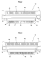
- FIGS. 2 and 3 are a top view and a bottom view of the electrical connector 10, respectively.
- the electrical connector 10 comprises a housing 12, an upper array of terminals 30 and a lower array of terminals 50 which are integrally molded with the housing 12, and grounding plate 70.
- the lower array of terminals 50 is omitted in FIG. 2
- the upper array of terminals 30 is omitted in FIG. 3 .
- the electrical connector 10 is adapted to allow a first member comprising an after-mentioned printed circuit board 26 and an after-mentioned external shell 27 to be connected thereto from the arrowed direction B in FIG. 1 , and allow a second member comprising a counterpart connector (not shown) to be connected thereto from the arrowed direction C in FIG. 1 .
- the first and second members are electrically connectable to each other through the terminal 30, 50 when they are connected to the electrical connector 10.
- FIG. 4 shows the first member in a state after being connected to the electrical connector 10 from the direction B
- FIG. 5 is a schematic sectional view taken along the line A-A in FIG. 4 .
- the first member to be connected to the electrical connector 10 from the direction B comprises a printed circuit board 26, and an external shell 27 attached to the printed circuit board 26 by a screw.
- the printed circuit board 26 is clamped between respective ones of after-mentioned wire connection portions (serving as first connection portions) 32 of the terminals 30 and after-mentioned wire connection portions (serving as first connection portions) 52 of the terminals 50 with a given contact pressure, and a plurality of tongue pieces 25 of the external shell 27 (which is illustrated only in FIG. 4 , and omitted in FIG.
- the second member to be connected to the electrical member 10 from the direction C is not illustrated, it may be considered that the second member has the same function as that of the first member illustrated in FIGS. 4 and 5 .
- the second member comprises a main body and an external shell.
- the main body is adapted to be brought into contact with after-mentioned terminal contact portions (serving as second contact portions) 34 of the terminals 30 and after-mentioned terminal contact portions (serving as second contact portions) 54 of the terminals 50, i.e., externally exposed portions 46, 48 of the terminals 30 and externally exposed portions 66 of the terminals 50
- the external shell is adapted to be brought into contact with an upper exposed portion 72 of the grounding plate 70 so as to be connected to ground.
- the upper exposed portion 72 and the lower exposed portion 74 are connected to each other inside the housing 12, and therefore may be considered as being electrically integral with each other.
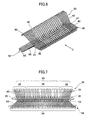
- FIG. 6 is a perspective view showing the arrangement of the upper array of terminals 30 and the lower array of terminals 50 in the electrical connector 10, wherein the housing 12 is removed for the sake of illustrative convenience.
- FIG. 7 is a front view showing the upper array of terminals 30 and the lower array of terminals 50 (together with the printed circuit board 26 for reference), when viewed in the arrowed direction D in FIG. 6 .
- FIG. 8 is a top view showing only the upper array of terminals 30, and
- FIG. 9 is a top view showing only the lower array of terminals 50.
- the terminals 30 of the upper array are arranged side-by-side in a horizontal direction
- the terminals 50 of the lower array are also arranged side-by-side in a horizontal direction and disposed under the terminals 30 of the upper array in a vertical direction.
- Each of the terminals 30 of the upper array has a first connection portion (wire connection portion) 32 and a second connection portion (terminal contact portion) 34
- each of the terminals 50 of the lower array has a first connection portion (wire connection portion) 52 and a second connection portion (terminal contact portion) 54.
- each of the terminals 30 of the upper array has a step between the first and second connection portions 32, 34
- each of the terminals 50 of the lower array has a step between the first and second connection portions 52, 54.
- each of the terminals 30 of the upper array has an obtusely inclined portion 40 which is obtusely inclined between the first and second connection portions 32, 34 thereof in a vertical direction
- each of the terminals 50 of the upper array has an obtusely inclined portion 60 which is obtusely inclined between the first and second connection portions 52, 54 thereof in the vertical direction.
- each of the obtusely inclined portions 40, 60 is formed to have a smooth inclined surface to effectively prevent deterioration in the high-speed transmission characteristics.
- the terminals 30 of the upper array consist of two types of terminals: two or more high-speed transmission terminals 36 adapted to be used for high-speed transmission, and the remaining normal terminals 38 other than the high-speed transmission terminals 36.
- the terminals 50 of the lower array consist only of terminals corresponding to the normal terminals 38 in the terminals 38 of the upper array.
- Each of the high-speed transmission terminals 36 included in the terminals 30 of the upper array is formed to have the same overall length and the same thickness in order to maintain high-speed transmission characteristics. Further, each of the high-speed transmission terminals 36 is formed to have a width dimension a in the horizontal direction greater than a width dimension b of each of the normal terminals 38 in the horizontal direction.
- the width dimension a is an optimal value derived from electrical properties of a material selected for the terminals 30 of the upper array.
- the high-speed transmission terminals 36 included in the terminals 30 of the upper array are arranged such that an inter-terminal pitch c in the first connection portion 32 thereof, i.e., a distance between respective centers of adjacent ones thereof, is equal to an inter-terminal pitch c in the second connection portions 34 thereof. That is, in the high-speed transmission terminals 36, an inter-terminal pitch in the wire connection portions is not changed from that in the terminal contact portions (terminal fitting portions).
- each of the high-speed transmission terminals 36 is a linear-shaped terminal 37 which linearly extends between the first and second connection portions 32, 34 in the horizontal direction.
- the linear-shaped high-speed transmission terminals 36 make it possible to more effectively prevent deterioration in the high-speed transmission characteristics. In cases where the high-speed transmission terminals 36 are used particularly for differential transmission, each of the high-speed transmission terminals 36 is required to have the same length. In such cases, the linear-shaped high-speed transmission terminals 36 make it possible to facilitate design for differential transmission.
- the normal terminals 38 included in the terminals 30 of the upper array together with the high-speed transmission terminals 36 are arranged such that an inter-terminal pitch d in the first connection portions 32 thereof is less than an inter-terminal pitch d' in the second connection portions 34 thereof. That is, in the normal terminals 38, the respective inter-terminal pitches in the first and second connection portions 32, 34 are different from each other.
- each of the normal terminals 38 is provided with a bent portion 39 which is bent between the first and second connection portions 32, 34 in the horizontal direction.
- the normal terminal 38 located closer to a center of the upper array in the horizontal direction has a smaller bending angle
- the normal terminal 38 located closer to each of opposite edges of the upper array in the horizontal direction has a larger bending angle.
- the high-speed transmission terminals 36 are distinguished from the remaining normal terminals 38, so as to satisfy a desired characteristic impedance. Further, in the terminals 30 of the upper array, the high-speed transmission terminals 36 are mixed with the normal terminals 38 in such a manner that the high-speed transmission terminals 36 are arranged to have an inter-terminal pitch different from that of the normal terminals 38, instead of forming all the terminals 30 as the high-speed transmission terminals 36. This makes it possible to facilitate reduction in overall size of the electrical connector, allow a larger number of terminals to be arranged within an existing limited terminal arrangement area (e.g., 50-pin area).
- an existing limited terminal arrangement area e.g., 50-pin area
- each of the high-speed transmission terminals 36 is formed to have the same length and a linear shape in consideration of differential signals and others and arranged in a central region of the electrical connector (a central region of the upper array) in paired relation with a ground terminal, and the normal terminals 38 are disposed on opposite sides of the central region in such a manner to reduce a horizontal distance on the side of the printed circuit board. This makes it possible to increase the number of contacts while maintaining an existing plug size, without spoiling the high-speed transmission characteristics. Further, the wire connection portions of the linear-shaped high-speed transmission terminals 36 and the normal terminals 38 having the reduced inter-terminal pitch can cope with a need for using a printed circuit board having the same size of an existing lower array of terminals 50.
- the terminals 50 of the lower array consisting only of the normal terminals are arranged such that an inter-terminal distance e in the first connection portions 52 thereof is less than an inter-terminal distance e' in the second connection portions 54 thereof, in the same manner as that in the normal terminals 38 included in the terminals 30 of the upper array. That is, the respective inter-terminal pitched in the first and second connection portions 52, 54 are different from each other.
- each of the normal terminals except a central one thereof, is provided with a bent portion 59 which is bent between the first and second connection portions 52, 54 in the horizontal direction, in the same manner as that in the normal terminals 38 included in the terminals 30 of the upper array.
- the normal terminal located closer to a center of the lower array in the horizontal direction has a smaller bending angle
- the normal terminal located closer to each of opposite edges of the lower array in the horizontal direction has a larger bending angle.
- each of the terminals of the upper and lower arrays except the wire connection portions 32, 52 (first connection portions) and the terminal contact portions 34, 54 (second connection portions), may be substantially fully covered by molding resin 12 to form a hermetic or air sealed structure.
- each of the terminals of the upper and lower arrays, except the terminal contact potions between respective ones of the terminals of the electrical connector and terminals of a counterpart connector, and the wire connection portions with the printed circuit board (or electrical wires) may be substantially fully covered by molding resin to form a single-piece structure.
Landscapes
- Details Of Connecting Devices For Male And Female Coupling (AREA)
- Coupling Device And Connection With Printed Circuit (AREA)
- Connector Housings Or Holding Contact Members (AREA)
Abstract
Description
- The present invention relates to an electrical connector, and more particularly to an electrical connector designed to change an inter-terminal pitch.
- In an electrical connector for use in medical apparatuses or the like, there are some cases in which only a specific part of a plurality of terminals are required to be compatible with high-speed transmission, as a particular usage mode. However, in a conventional electrical connector, a plurality of terminals are produced to have the same dimensions and the same configuration, and arranged at the same pitch, as disclosed, for example, in
JP 2002-214538A
[Patent Document 1]JP 2002-214538A - In view of the above problem in the conventional electrical connector, it is an object of the present invention to provide an electrical connector capable of achieving satisfactory high-speed transmission characteristics, while facilitating a reduction in overall size thereof, in such a manner that a part of a plurality of terminals are defined as high-speed transmission terminals, i.e., distinguished from the remaining normal terminals, and designed to have a terminal configuration and a pitch dimension which satisfy a desired characteristic impedance.
- In order to achieve the above object, according to one aspect of the present invention, there is provided an electrical connector which comprises a plurality of terminals arranged side-by-side in a horizontal direction, wherein each of the terminals has a first connection portion adapted to be connected with one of two members electrically connectable to each other via the electrical connector, and a second connection portion adapted to be connected with the other member. In the electrical connector, two or more first terminals consisting of a part of the terminals are arranged such that an inter-terminal pitch in the first connection portions thereof is equal to that in the second connection portions thereof, and two or more second terminals consisting of the remaining terminals other than the first terminals are arranged such that an inter-terminal pitch in the first connection portions thereof is less than that in the second connection portions thereof.
- In the electrical connector of the present invention, the plurality of terminals may include an upper array of terminals arranged side-by-side in a horizontal direction, and a lower array of terminals arranged side-by-side in a horizontal direction and disposed on a lower side of the upper array in a vertical direction, wherein each of the terminals of the upper and lower arrays has a first connection portion adapted to be connected with one of two members electrically connectable to each other via the electrical connector, and a second connection portion adapted to be connected with the other member, and wherein: two or more first terminals consisting of a part of the terminals of the upper array are arranged such that an inter-terminal pitch in the first connection portions thereof is equal to that in the second connection portions thereof; two or more second terminals consisting of the remaining terminals of the upper array other than the first terminals are arranged such that an inter-terminal pitch in the first connection portions thereof is less than that in the second connection portions thereof; and all the terminals of the lower array are arranged such that an inter-terminal pitch in the first connection portions thereof is less than that in the second connection portions thereof.
- Preferably, in the electrical connector of the present invention, each of the first terminals linearly extends between the first and second connection portions thereof in a horizontal direction, and each of the second terminals has a bent portion which is bent between the first and second connection portions thereof in the horizontal direction.
- Preferably, in the electrical connector of the present invention, each of the terminals has an obtusely inclined portion which is obtusely inclined between the first and second connection portions thereof in a vertical direction.
- Preferably, in the above electrical connector, the first terminals are disposed in a central region, and the second terminals are disposed on opposite sides of the central region.
- Preferably, in the above electrical connector, each of the first terminals has a width in the horizontal direction greater than that of each of the second terminals.
- In the electrical connector of the present invention, each of the first terminals may be a high-speed transmission terminal.
- In the above electrical connector, when the first terminals include a pair of terminals adapted to be used for differential transmission, each of the pair of terminals preferably has a same length.
- In the electrical connector of the present invention, when the first connection portion is used as a wire connection portion, and the second connection portion is used as a terminal contact portion, each of the terminals, except the wire connection portions and the terminal contact portions, is preferably covered by molding resin to form an air sealed structure.
- According to a second aspect of the present invention, there is provided an electrical connector which comprises: an array of terminals arranged side-by-side in a horizontal direction, wherein each of the terminals of the array has a first connection portion adapted to be connected with a first one of two members electrically connectable to each other via the electrical connector, and a second connection portion adapted to be connected with the other, second, member; and a grounding plate. In the electrical connector, two or more first terminals consisting of a part of the terminals of the array are arranged such that an inter-terminal pitch in the first connection portions thereof is equal to that in the second connection portions thereof, and two or more second terminals consisting of the remaining terminals of the array other than the first terminals are arranged such that an inter-terminal pitch in the first connection portions thereof is less than that in the second connection portions thereof. Further, the first member includes a printed circuit board, and an external shell attached to the printed circuit board. The electrical connector is designed such that, when the first member is attached to the electrical connector, the first connection portions of the terminals of the array are brought into contact with the printed circuit board, and the grounding plate is brought into contact with the external shell in a vicinity of the first connection portions of the terminals of the array so as to be connected to ground.
-
-
FIG. 1 is a perspective view showing an electrical connector according to one embodiment of the present invention. -
FIG. 2 is a top view showing the electrical connector inFIG. 1 . -
FIG. 3 is a bottom view showing the electrical connector inFIG. 1 . -
FIG. 4 is a perspective view showing the electrical connector inFIG. 1 together with a member attached thereto. -
FIG. 5 is a sectional view taken along the line A-A inFIG. 4 . -
FIG. 6 is a perspective view showing an upper array of terminals and a lower array of terminals. -
FIG. 7 is a front view showing the upper array of terminals and the lower array of terminals. -
FIG. 8 is a top view showing only the upper array of terminals. -
FIG. 9 is a top view showing only the lower array of terminals. - With reference to the accompanying drawings, the present invention will now be described based on one preferred embodiment thereof.
-
FIG. 1 is a perspective view showing anelectrical connector 10 according to one embodiment of the present invention.FIGS. 2 and 3 are a top view and a bottom view of theelectrical connector 10, respectively. Theelectrical connector 10 comprises ahousing 12, an upper array ofterminals 30 and a lower array ofterminals 50 which are integrally molded with thehousing 12, andgrounding plate 70. For easy understanding, the lower array ofterminals 50 is omitted inFIG. 2 , and the upper array ofterminals 30 is omitted inFIG. 3 . - The
electrical connector 10 is adapted to allow a first member comprising an after-mentionedprinted circuit board 26 and an after-mentionedexternal shell 27 to be connected thereto from the arrowed direction B inFIG. 1 , and allow a second member comprising a counterpart connector (not shown) to be connected thereto from the arrowed direction C inFIG. 1 . The first and second members are electrically connectable to each other through theterminal electrical connector 10.FIG. 4 shows the first member in a state after being connected to theelectrical connector 10 from the direction B, andFIG. 5 is a schematic sectional view taken along the line A-A inFIG. 4 . - The first member to be connected to the
electrical connector 10 from the direction B comprises a printedcircuit board 26, and anexternal shell 27 attached to the printedcircuit board 26 by a screw. When the first member is connected to the electricallyconnector 10, the printedcircuit board 26 is clamped between respective ones of after-mentioned wire connection portions (serving as first connection portions) 32 of theterminals 30 and after-mentioned wire connection portions (serving as first connection portions) 52 of theterminals 50 with a given contact pressure, and a plurality oftongue pieces 25 of the external shell 27 (which is illustrated only inFIG. 4 , and omitted inFIG. 5 ) are brought into contact with a lower exposedportion 74 of thegrounding plate 70 provided to protrude from thehousing 12 in the same direction as that of theterminals terminals terminals external shell 27 is connected to ground together with the printedcircuit board 26. Theexternal shell 27 makes it possible to shield the printedcircuit board 26, and maintain high-speed transmission as an assembly. One end of an electrical wire (not shown) is connected to a far side of the printedcircuit board 26 relative to theelectrical connector 10. The electric wire has the other end connected to another device. - Although the second member to be connected to the
electrical member 10 from the direction C is not illustrated, it may be considered that the second member has the same function as that of the first member illustrated inFIGS. 4 and5 . Specifically, the second member comprises a main body and an external shell. The main body is adapted to be brought into contact with after-mentioned terminal contact portions (serving as second contact portions) 34 of theterminals 30 and after-mentioned terminal contact portions (serving as second contact portions) 54 of theterminals 50, i.e., externally exposedportions terminals 30 and externally exposedportions 66 of theterminals 50, and the external shell is adapted to be brought into contact with an upper exposedportion 72 of thegrounding plate 70 so as to be connected to ground. The upper exposedportion 72 and the lower exposedportion 74 are connected to each other inside thehousing 12, and therefore may be considered as being electrically integral with each other. - With reference to
FIGS. 6 and9 , an arrangement of the upper array ofterminals 30 and the lower array ofterminals 50 will be described below.FIG. 6 is a perspective view showing the arrangement of the upper array ofterminals 30 and the lower array ofterminals 50 in theelectrical connector 10, wherein thehousing 12 is removed for the sake of illustrative convenience.FIG. 7 is a front view showing the upper array ofterminals 30 and the lower array of terminals 50 (together with theprinted circuit board 26 for reference), when viewed in the arrowed direction D inFIG. 6 .FIG. 8 is a top view showing only the upper array ofterminals 30, andFIG. 9 is a top view showing only the lower array ofterminals 50. - As is clearly shown in
FIGS. 6 to 9 , theterminals 30 of the upper array are arranged side-by-side in a horizontal direction, and theterminals 50 of the lower array are also arranged side-by-side in a horizontal direction and disposed under theterminals 30 of the upper array in a vertical direction. Each of theterminals 30 of the upper array has a first connection portion (wire connection portion) 32 and a second connection portion (terminal contact portion) 34, and each of theterminals 50 of the lower array has a first connection portion (wire connection portion) 52 and a second connection portion (terminal contact portion) 54. Each of theterminals 30 of the upper array has a step between the first andsecond connection portions terminals 50 of the lower array has a step between the first andsecond connection portions terminals 30 of the upper array has an obtuselyinclined portion 40 which is obtusely inclined between the first andsecond connection portions terminals 50 of the upper array has an obtuselyinclined portion 60 which is obtusely inclined between the first andsecond connection portions inclined portions - It should be noted that the
terminals 30 of the upper array consist of two types of terminals: two or more high-speed transmission terminals 36 adapted to be used for high-speed transmission, and the remainingnormal terminals 38 other than the high-speed transmission terminals 36. Differently from theterminals 30 of the upper array, theterminals 50 of the lower array consist only of terminals corresponding to thenormal terminals 38 in theterminals 38 of the upper array. - Each of the high-
speed transmission terminals 36 included in theterminals 30 of the upper array is formed to have the same overall length and the same thickness in order to maintain high-speed transmission characteristics. Further, each of the high-speed transmission terminals 36 is formed to have a width dimension a in the horizontal direction greater than a width dimension b of each of thenormal terminals 38 in the horizontal direction. The width dimension a is an optimal value derived from electrical properties of a material selected for theterminals 30 of the upper array. - The high-
speed transmission terminals 36 included in theterminals 30 of the upper array are arranged such that an inter-terminal pitch c in thefirst connection portion 32 thereof, i.e., a distance between respective centers of adjacent ones thereof, is equal to an inter-terminal pitch c in thesecond connection portions 34 thereof. That is, in the high-speed transmission terminals 36, an inter-terminal pitch in the wire connection portions is not changed from that in the terminal contact portions (terminal fitting portions). Further, each of the high-speed transmission terminals 36 is a linear-shapedterminal 37 which linearly extends between the first andsecond connection portions speed transmission terminals 36 make it possible to more effectively prevent deterioration in the high-speed transmission characteristics. In cases where the high-speed transmission terminals 36 are used particularly for differential transmission, each of the high-speed transmission terminals 36 is required to have the same length. In such cases, the linear-shaped high-speed transmission terminals 36 make it possible to facilitate design for differential transmission. - Differently from the high-
speed transmission terminals 36, thenormal terminals 38 included in theterminals 30 of the upper array together with the high-speed transmission terminals 36 are arranged such that an inter-terminal pitch d in thefirst connection portions 32 thereof is less than an inter-terminal pitch d' in thesecond connection portions 34 thereof. That is, in thenormal terminals 38, the respective inter-terminal pitches in the first andsecond connection portions normal terminals 38 is provided with abent portion 39 which is bent between the first andsecond connection portions bent portions 39, thenormal terminal 38 located closer to a center of the upper array in the horizontal direction has a smaller bending angle, and thenormal terminal 38 located closer to each of opposite edges of the upper array in the horizontal direction has a larger bending angle. - As described above, in the
terminals 30 of the upper array, the high-speed transmission terminals 36 are distinguished from the remainingnormal terminals 38, so as to satisfy a desired characteristic impedance. Further, in theterminals 30 of the upper array, the high-speed transmission terminals 36 are mixed with thenormal terminals 38 in such a manner that the high-speed transmission terminals 36 are arranged to have an inter-terminal pitch different from that of thenormal terminals 38, instead of forming all theterminals 30 as the high-speed transmission terminals 36. This makes it possible to facilitate reduction in overall size of the electrical connector, allow a larger number of terminals to be arranged within an existing limited terminal arrangement area (e.g., 50-pin area). Further, each of the high-speed transmission terminals 36 is formed to have the same length and a linear shape in consideration of differential signals and others and arranged in a central region of the electrical connector (a central region of the upper array) in paired relation with a ground terminal, and thenormal terminals 38 are disposed on opposite sides of the central region in such a manner to reduce a horizontal distance on the side of the printed circuit board. This makes it possible to increase the number of contacts while maintaining an existing plug size, without spoiling the high-speed transmission characteristics. Further, the wire connection portions of the linear-shaped high-speed transmission terminals 36 and thenormal terminals 38 having the reduced inter-terminal pitch can cope with a need for using a printed circuit board having the same size of an existing lower array ofterminals 50. - Differently from the
terminals 30 of the upper array which comprise two types of terminals consisting of the high-speed transmission terminals 36 and thenormal terminals 30, theterminals 50 of the lower array consisting only of the normal terminals are arranged such that an inter-terminal distance e in thefirst connection portions 52 thereof is less than an inter-terminal distance e' in thesecond connection portions 54 thereof, in the same manner as that in thenormal terminals 38 included in theterminals 30 of the upper array. That is, the respective inter-terminal pitched in the first andsecond connection portions bent portion 59 which is bent between the first andsecond connection portions normal terminals 38 included in theterminals 30 of the upper array. As seen inFIG. 9 , the normal terminal located closer to a center of the lower array in the horizontal direction has a smaller bending angle, and the normal terminal located closer to each of opposite edges of the lower array in the horizontal direction has a larger bending angle. - For example, in cases where the electrical connector according to this embodiment is used for a medical apparatus or the like, water or blood is likely to attach thereon to give rise to a need for cleaning. Thus, it is desirable to enhance waterproofing property thereof. For this purpose, each of the terminals of the upper and lower arrays, except the
wire connection portions 32, 52 (first connection portions) and theterminal contact portions 34, 54 (second connection portions), may be substantially fully covered by moldingresin 12 to form a hermetic or air sealed structure. Further, in order to maintain a sealing performance, each of the terminals of the upper and lower arrays, except the terminal contact potions between respective ones of the terminals of the electrical connector and terminals of a counterpart connector, and the wire connection portions with the printed circuit board (or electrical wires) may be substantially fully covered by molding resin to form a single-piece structure.
Claims (10)
- An electrical connector comprising a plurality of terminals arranged side-by-side in a horizontal direction, each of the terminals having a first connection portion adapted to be connected with one of two members electrically connectable to each other via the electrical connector, and a second connection portion adapted to be connected with the other member, wherein:two or more first terminals consisting of a part of the terminals are arranged such that an inter-terminal pitch in the first connection portions thereof is equal to that in the second connection portions thereof; andtwo or more second terminals consisting of the remaining terminals other than the first terminals are arranged such that an inter-terminal pitch in the first connection portions thereof is less than that in the second connection portions thereof.
- The electrical connector as defined in claim 1, wherein the plurality of terminals include an upper array of terminals arranged side-by-side in a horizontal direction, and a lower array of terminals arranged side-by-side in a horizontal direction and disposed on a lower side of the upper array in a vertical direction, each of the terminals of the upper and lower arrays having a first connection portion adapted to be connected with one of two members electrically connectable to each other via the electrical connector, and a second connection portion adapted to be connected with the other member, wherein:two or more first terminals consisting of a part of the terminals of the upper array are arranged such that an inter-terminal pitch in the first connection portions thereof is equal to that in the second connection portions thereof;two or more second terminals consisting of the remaining terminals of the upper array other than the first terminals are arranged such that an inter-terminal pitch in the first connection portions thereof is less than that in the second connection portions thereof; andall the terminals of the lower array are arranged such that an inter-terminal pitch in the first connection portions thereof is less than that in the second connection portions thereof.
- The electrical connector as defined in claim 1 or 2, wherein each of the first terminals linearly extends between the first and second connection portions thereof in a horizontal direction, and each of the second terminals has a bent portion which is bent between the first and second connection portions thereof in the horizontal direction.
- The electrical connector as defined in any one of claims 1 to 3, wherein each of the terminals has an obtusely inclined portion which is obtusely inclined between the first and second connection portions thereof in a vertical direction.
- The electrical connector as defined in any one of claims 1 to 4, wherein the first terminals are disposed in a central region, and the second terminals are disposed on opposite sides of the central region.
- The electrical connector as defined in any one of claims 1 to 5, wherein each of the first terminals has a width in the horizontal direction greater than that of each of the second terminals.
- The electrical connector as defined in any one of claims 1 to 6, wherein each of the first terminals is a high-speed transmission terminal.
- The electrical connector as defined in any one of claims 1 to 7, wherein the first terminals include a pair of terminals adapted to be used for differential transmission, each of the pair of terminals having a same length.
- The electrical connector as defined in any one of claims 1 to 8, wherein the first connection portion is used as a wire connection portion, and the second connection portion is used as a terminal contact portion, wherein each of the terminals, except the wire connection portions and the terminal contact portions, is covered by molding resin to form an air sealed structure.
- An electrical connector comprising: an array of terminals arranged side-by-side in a horizontal direction, each of the terminals of the array having a first connection portion adapted to be connected with a first one of two members electrically connectable to each other via the electrical connector, and a second connection portion adapted to be connected with the other, second, member; and a grounding plate, wherein:two or more first terminals consisting of a part of the terminals of the array are arranged such that an inter-terminal pitch in the first connection portions thereof is equal to that in the second connection portions thereof;two or more second terminals consisting of the remaining terminals of the array other than the first terminals are arranged such that an inter-terminal pitch in the first connection portions thereof is less than that in the second connection portions thereof; andthe first member includes a printed circuit board, and an external shell attached to the printed circuit board,wherein the electrical connector is designed such that, when the first member is attached to the electrical connector, the first connection portions of the terminals of the array are brought into contact with the printed circuit board, and the grounding plate is brought into contact with the external shell in a vicinity of the first connection portions of the terminals of the array so as to be connected to ground.
Applications Claiming Priority (1)
| Application Number | Priority Date | Filing Date | Title |
|---|---|---|---|
| JP2008198413A JP5059712B2 (en) | 2008-07-31 | 2008-07-31 | Electrical connector |
Publications (2)
| Publication Number | Publication Date |
|---|---|
| EP2149942A1 true EP2149942A1 (en) | 2010-02-03 |
| EP2149942B1 EP2149942B1 (en) | 2012-09-26 |
Family
ID=40756352
Family Applications (1)
| Application Number | Title | Priority Date | Filing Date |
|---|---|---|---|
| EP09006034A Not-in-force EP2149942B1 (en) | 2008-07-31 | 2009-04-30 | Electrical connector |
Country Status (4)
| Country | Link |
|---|---|
| US (1) | US7922500B2 (en) |
| EP (1) | EP2149942B1 (en) |
| JP (1) | JP5059712B2 (en) |
| CN (1) | CN101640324B (en) |
Cited By (1)
| Publication number | Priority date | Publication date | Assignee | Title |
|---|---|---|---|---|
| WO2012080843A3 (en) * | 2010-12-13 | 2012-11-15 | Fci | High speed edge card connector |
Families Citing this family (2)
| Publication number | Priority date | Publication date | Assignee | Title |
|---|---|---|---|---|
| USD606497S1 (en) | 2009-01-16 | 2009-12-22 | Fci Americas Technology, Inc. | Vertical electrical connector |
| JP7444005B2 (en) * | 2020-09-16 | 2024-03-06 | 住友電装株式会社 | connector |
Citations (5)
| Publication number | Priority date | Publication date | Assignee | Title |
|---|---|---|---|---|
| US5975944A (en) | 1996-06-28 | 1999-11-02 | The Whitaker Corporation | Connector for pitch spaced electrical cables |
| JP2002214538A (en) | 2001-01-19 | 2002-07-31 | Olympus Optical Co Ltd | Connector unit for endoscope |
| US20040043658A1 (en) | 2002-09-04 | 2004-03-04 | Ko David Tso-Chin | Low profile cable connector assembly with multi-pitch contacts |
| WO2006055698A1 (en) | 2004-11-17 | 2006-05-26 | Molex Incorporated | Interconnect device and the assembly same is used therein |
| US20080085581A1 (en) * | 2006-10-10 | 2008-04-10 | Jin-Ho Kim | Methods of forming a semiconductor device that allow patterns in different regions that have different pitches to be connected |
Family Cites Families (7)
| Publication number | Priority date | Publication date | Assignee | Title |
|---|---|---|---|---|
| JP3238895B2 (en) * | 1997-08-28 | 2001-12-17 | ヒロセ電機株式会社 | Modular jack |
| DE60014385T2 (en) * | 1999-07-16 | 2006-02-23 | Molex Inc., Lisle | IMPEDANCE-CONNECTED CONNECTOR |
| SG118181A1 (en) * | 2003-03-25 | 2006-01-27 | Fci Asia Technology Pte Ltd | High density electrical connector |
| JP2005149770A (en) * | 2003-11-11 | 2005-06-09 | Japan Aviation Electronics Industry Ltd | connector |
| JP2007080782A (en) * | 2005-09-16 | 2007-03-29 | Japan Aviation Electronics Industry Ltd | Electrical connector |
| JP2007165195A (en) * | 2005-12-15 | 2007-06-28 | Matsushita Electric Works Ltd | Connector |
| CN200983449Y (en) * | 2006-11-24 | 2007-11-28 | 建舜电子制造股份有限公司 | Connector Socket for High Density Multimedia Interface |
-
2008
- 2008-07-31 JP JP2008198413A patent/JP5059712B2/en active Active
-
2009
- 2009-04-28 CN CN2009101354835A patent/CN101640324B/en not_active Expired - Fee Related
- 2009-04-30 EP EP09006034A patent/EP2149942B1/en not_active Not-in-force
- 2009-07-21 US US12/507,028 patent/US7922500B2/en active Active
Patent Citations (5)
| Publication number | Priority date | Publication date | Assignee | Title |
|---|---|---|---|---|
| US5975944A (en) | 1996-06-28 | 1999-11-02 | The Whitaker Corporation | Connector for pitch spaced electrical cables |
| JP2002214538A (en) | 2001-01-19 | 2002-07-31 | Olympus Optical Co Ltd | Connector unit for endoscope |
| US20040043658A1 (en) | 2002-09-04 | 2004-03-04 | Ko David Tso-Chin | Low profile cable connector assembly with multi-pitch contacts |
| WO2006055698A1 (en) | 2004-11-17 | 2006-05-26 | Molex Incorporated | Interconnect device and the assembly same is used therein |
| US20080085581A1 (en) * | 2006-10-10 | 2008-04-10 | Jin-Ho Kim | Methods of forming a semiconductor device that allow patterns in different regions that have different pitches to be connected |
Cited By (2)
| Publication number | Priority date | Publication date | Assignee | Title |
|---|---|---|---|---|
| WO2012080843A3 (en) * | 2010-12-13 | 2012-11-15 | Fci | High speed edge card connector |
| US9385477B2 (en) | 2010-12-13 | 2016-07-05 | Fci | High speed edge card connector |
Also Published As
| Publication number | Publication date |
|---|---|
| US7922500B2 (en) | 2011-04-12 |
| EP2149942B1 (en) | 2012-09-26 |
| CN101640324A (en) | 2010-02-03 |
| CN101640324B (en) | 2013-04-24 |
| US20100029098A1 (en) | 2010-02-04 |
| JP5059712B2 (en) | 2012-10-31 |
| JP2010040197A (en) | 2010-02-18 |
Similar Documents
| Publication | Publication Date | Title |
|---|---|---|
| US9755380B2 (en) | Flippable electrical connector | |
| US7465186B2 (en) | Electric connector | |
| US9653849B2 (en) | Electrical connector having good anti-EMI perfprmance | |
| US6607400B1 (en) | Low profile RF connector assembly | |
| US9172194B2 (en) | Coaxial connector plug | |
| US6672887B1 (en) | Electrical connector having grounding bridge | |
| US20160233631A1 (en) | Electrical connector | |
| CN201797103U (en) | electrical connector | |
| US9065214B2 (en) | Electrical connector having a ground contact with a solder portion and a pair of grounding contact portions | |
| US20070275579A1 (en) | Electrical connector with improved metallic shell | |
| JP5312288B2 (en) | Shield case and connector provided with the same | |
| US20050042924A1 (en) | Electrical connector having shielding plates | |
| US20130149908A1 (en) | Hermaphroditic board to board connector and assembly thereof with offset contact arrangement | |
| US20090247014A1 (en) | Electrical connector having a shell with a portion retained in an insulative housing | |
| CN101667695A (en) | Connector device having shielding function | |
| US7726990B2 (en) | Electrical connector having improved terminal switch arrangement | |
| KR101871038B1 (en) | Coaxial connector | |
| US7789678B2 (en) | Multipolar connector and portable radio terminal or small-sized electronic device using multipolar connector | |
| US20240113477A1 (en) | Connector | |
| US9711912B2 (en) | Cable connector assembly with improved insulative member | |
| JP5587714B2 (en) | Shield case, connector and electronic equipment | |
| US7922500B2 (en) | Electrical connector | |
| US7445470B2 (en) | Electrical connector with improved housing | |
| CN208797209U (en) | Electric connector | |
| KR20180054230A (en) | Coaxial connector plug and RF connector including the same |
Legal Events
| Date | Code | Title | Description |
|---|---|---|---|
| PUAI | Public reference made under article 153(3) epc to a published international application that has entered the european phase |
Free format text: ORIGINAL CODE: 0009012 |
|
| AK | Designated contracting states |
Kind code of ref document: A1 Designated state(s): AT BE BG CH CY CZ DE DK EE ES FI FR GB GR HR HU IE IS IT LI LT LU LV MC MK MT NL NO PL PT RO SE SI SK TR |
|
| AX | Request for extension of the european patent |
Extension state: AL BA RS |
|
| 17P | Request for examination filed |
Effective date: 20100728 |
|
| 17Q | First examination report despatched |
Effective date: 20100907 |
|
| RAP1 | Party data changed (applicant data changed or rights of an application transferred) |
Owner name: OLYMPUS MEDICAL SYSTEMS CORP. |
|
| REG | Reference to a national code |
Ref country code: DE Ref legal event code: R079 Ref document number: 602009009939 Country of ref document: DE Free format text: PREVIOUS MAIN CLASS: H01R0031060000 Ipc: H01R0012720000 |
|
| GRAP | Despatch of communication of intention to grant a patent |
Free format text: ORIGINAL CODE: EPIDOSNIGR1 |
|
| RIC1 | Information provided on ipc code assigned before grant |
Ipc: H01R 12/72 20110101AFI20120502BHEP Ipc: H01R 31/06 20060101ALI20120502BHEP Ipc: H01R 13/6474 20110101ALI20120502BHEP |
|
| GRAS | Grant fee paid |
Free format text: ORIGINAL CODE: EPIDOSNIGR3 |
|
| GRAA | (expected) grant |
Free format text: ORIGINAL CODE: 0009210 |
|
| AK | Designated contracting states |
Kind code of ref document: B1 Designated state(s): AT BE BG CH CY CZ DE DK EE ES FI FR GB GR HR HU IE IS IT LI LT LU LV MC MK MT NL NO PL PT RO SE SI SK TR |
|
| REG | Reference to a national code |
Ref country code: GB Ref legal event code: FG4D |
|
| REG | Reference to a national code |
Ref country code: CH Ref legal event code: EP |
|
| REG | Reference to a national code |
Ref country code: AT Ref legal event code: REF Ref document number: 577397 Country of ref document: AT Kind code of ref document: T Effective date: 20121015 |
|
| REG | Reference to a national code |
Ref country code: IE Ref legal event code: FG4D |
|
| REG | Reference to a national code |
Ref country code: DE Ref legal event code: R096 Ref document number: 602009009939 Country of ref document: DE Effective date: 20121122 |
|
| PG25 | Lapsed in a contracting state [announced via postgrant information from national office to epo] |
Ref country code: LT Free format text: LAPSE BECAUSE OF FAILURE TO SUBMIT A TRANSLATION OF THE DESCRIPTION OR TO PAY THE FEE WITHIN THE PRESCRIBED TIME-LIMIT Effective date: 20120926 Ref country code: NO Free format text: LAPSE BECAUSE OF FAILURE TO SUBMIT A TRANSLATION OF THE DESCRIPTION OR TO PAY THE FEE WITHIN THE PRESCRIBED TIME-LIMIT Effective date: 20121226 Ref country code: HR Free format text: LAPSE BECAUSE OF FAILURE TO SUBMIT A TRANSLATION OF THE DESCRIPTION OR TO PAY THE FEE WITHIN THE PRESCRIBED TIME-LIMIT Effective date: 20120926 Ref country code: FI Free format text: LAPSE BECAUSE OF FAILURE TO SUBMIT A TRANSLATION OF THE DESCRIPTION OR TO PAY THE FEE WITHIN THE PRESCRIBED TIME-LIMIT Effective date: 20120926 |
|
| REG | Reference to a national code |
Ref country code: AT Ref legal event code: MK05 Ref document number: 577397 Country of ref document: AT Kind code of ref document: T Effective date: 20120926 |
|
| REG | Reference to a national code |
Ref country code: LT Ref legal event code: MG4D Effective date: 20120926 |
|
| REG | Reference to a national code |
Ref country code: NL Ref legal event code: VDEP Effective date: 20120926 |
|
| PG25 | Lapsed in a contracting state [announced via postgrant information from national office to epo] |
Ref country code: GR Free format text: LAPSE BECAUSE OF FAILURE TO SUBMIT A TRANSLATION OF THE DESCRIPTION OR TO PAY THE FEE WITHIN THE PRESCRIBED TIME-LIMIT Effective date: 20121227 Ref country code: SE Free format text: LAPSE BECAUSE OF FAILURE TO SUBMIT A TRANSLATION OF THE DESCRIPTION OR TO PAY THE FEE WITHIN THE PRESCRIBED TIME-LIMIT Effective date: 20120926 Ref country code: LV Free format text: LAPSE BECAUSE OF FAILURE TO SUBMIT A TRANSLATION OF THE DESCRIPTION OR TO PAY THE FEE WITHIN THE PRESCRIBED TIME-LIMIT Effective date: 20120926 Ref country code: SI Free format text: LAPSE BECAUSE OF FAILURE TO SUBMIT A TRANSLATION OF THE DESCRIPTION OR TO PAY THE FEE WITHIN THE PRESCRIBED TIME-LIMIT Effective date: 20120926 |
|
| PG25 | Lapsed in a contracting state [announced via postgrant information from national office to epo] |
Ref country code: EE Free format text: LAPSE BECAUSE OF FAILURE TO SUBMIT A TRANSLATION OF THE DESCRIPTION OR TO PAY THE FEE WITHIN THE PRESCRIBED TIME-LIMIT Effective date: 20120926 Ref country code: BE Free format text: LAPSE BECAUSE OF FAILURE TO SUBMIT A TRANSLATION OF THE DESCRIPTION OR TO PAY THE FEE WITHIN THE PRESCRIBED TIME-LIMIT Effective date: 20120926 Ref country code: CZ Free format text: LAPSE BECAUSE OF FAILURE TO SUBMIT A TRANSLATION OF THE DESCRIPTION OR TO PAY THE FEE WITHIN THE PRESCRIBED TIME-LIMIT Effective date: 20120926 Ref country code: ES Free format text: LAPSE BECAUSE OF FAILURE TO SUBMIT A TRANSLATION OF THE DESCRIPTION OR TO PAY THE FEE WITHIN THE PRESCRIBED TIME-LIMIT Effective date: 20130106 Ref country code: IS Free format text: LAPSE BECAUSE OF FAILURE TO SUBMIT A TRANSLATION OF THE DESCRIPTION OR TO PAY THE FEE WITHIN THE PRESCRIBED TIME-LIMIT Effective date: 20130126 Ref country code: NL Free format text: LAPSE BECAUSE OF FAILURE TO SUBMIT A TRANSLATION OF THE DESCRIPTION OR TO PAY THE FEE WITHIN THE PRESCRIBED TIME-LIMIT Effective date: 20120926 Ref country code: RO Free format text: LAPSE BECAUSE OF FAILURE TO SUBMIT A TRANSLATION OF THE DESCRIPTION OR TO PAY THE FEE WITHIN THE PRESCRIBED TIME-LIMIT Effective date: 20120926 |
|
| PG25 | Lapsed in a contracting state [announced via postgrant information from national office to epo] |
Ref country code: CY Free format text: LAPSE BECAUSE OF FAILURE TO SUBMIT A TRANSLATION OF THE DESCRIPTION OR TO PAY THE FEE WITHIN THE PRESCRIBED TIME-LIMIT Effective date: 20120926 Ref country code: PT Free format text: LAPSE BECAUSE OF FAILURE TO SUBMIT A TRANSLATION OF THE DESCRIPTION OR TO PAY THE FEE WITHIN THE PRESCRIBED TIME-LIMIT Effective date: 20130128 Ref country code: SK Free format text: LAPSE BECAUSE OF FAILURE TO SUBMIT A TRANSLATION OF THE DESCRIPTION OR TO PAY THE FEE WITHIN THE PRESCRIBED TIME-LIMIT Effective date: 20120926 Ref country code: PL Free format text: LAPSE BECAUSE OF FAILURE TO SUBMIT A TRANSLATION OF THE DESCRIPTION OR TO PAY THE FEE WITHIN THE PRESCRIBED TIME-LIMIT Effective date: 20120926 |
|
| PG25 | Lapsed in a contracting state [announced via postgrant information from national office to epo] |
Ref country code: AT Free format text: LAPSE BECAUSE OF FAILURE TO SUBMIT A TRANSLATION OF THE DESCRIPTION OR TO PAY THE FEE WITHIN THE PRESCRIBED TIME-LIMIT Effective date: 20120926 |
|
| PG25 | Lapsed in a contracting state [announced via postgrant information from national office to epo] |
Ref country code: BG Free format text: LAPSE BECAUSE OF FAILURE TO SUBMIT A TRANSLATION OF THE DESCRIPTION OR TO PAY THE FEE WITHIN THE PRESCRIBED TIME-LIMIT Effective date: 20121226 Ref country code: DK Free format text: LAPSE BECAUSE OF FAILURE TO SUBMIT A TRANSLATION OF THE DESCRIPTION OR TO PAY THE FEE WITHIN THE PRESCRIBED TIME-LIMIT Effective date: 20120926 |
|
| PLBE | No opposition filed within time limit |
Free format text: ORIGINAL CODE: 0009261 |
|
| STAA | Information on the status of an ep patent application or granted ep patent |
Free format text: STATUS: NO OPPOSITION FILED WITHIN TIME LIMIT |
|
| PG25 | Lapsed in a contracting state [announced via postgrant information from national office to epo] |
Ref country code: IT Free format text: LAPSE BECAUSE OF FAILURE TO SUBMIT A TRANSLATION OF THE DESCRIPTION OR TO PAY THE FEE WITHIN THE PRESCRIBED TIME-LIMIT Effective date: 20120926 |
|
| 26N | No opposition filed |
Effective date: 20130627 |
|
| REG | Reference to a national code |
Ref country code: DE Ref legal event code: R097 Ref document number: 602009009939 Country of ref document: DE Effective date: 20130627 |
|
| PG25 | Lapsed in a contracting state [announced via postgrant information from national office to epo] |
Ref country code: MC Free format text: LAPSE BECAUSE OF FAILURE TO SUBMIT A TRANSLATION OF THE DESCRIPTION OR TO PAY THE FEE WITHIN THE PRESCRIBED TIME-LIMIT Effective date: 20120926 |
|
| REG | Reference to a national code |
Ref country code: CH Ref legal event code: PL |
|
| GBPC | Gb: european patent ceased through non-payment of renewal fee |
Effective date: 20130430 |
|
| REG | Reference to a national code |
Ref country code: IE Ref legal event code: MM4A |
|
| PG25 | Lapsed in a contracting state [announced via postgrant information from national office to epo] |
Ref country code: LI Free format text: LAPSE BECAUSE OF NON-PAYMENT OF DUE FEES Effective date: 20130430 Ref country code: CH Free format text: LAPSE BECAUSE OF NON-PAYMENT OF DUE FEES Effective date: 20130430 Ref country code: GB Free format text: LAPSE BECAUSE OF NON-PAYMENT OF DUE FEES Effective date: 20130430 |
|
| REG | Reference to a national code |
Ref country code: FR Ref legal event code: ST Effective date: 20131231 |
|
| PG25 | Lapsed in a contracting state [announced via postgrant information from national office to epo] |
Ref country code: FR Free format text: LAPSE BECAUSE OF NON-PAYMENT OF DUE FEES Effective date: 20130430 |
|
| PG25 | Lapsed in a contracting state [announced via postgrant information from national office to epo] |
Ref country code: IE Free format text: LAPSE BECAUSE OF NON-PAYMENT OF DUE FEES Effective date: 20130430 |
|
| PG25 | Lapsed in a contracting state [announced via postgrant information from national office to epo] |
Ref country code: MT Free format text: LAPSE BECAUSE OF FAILURE TO SUBMIT A TRANSLATION OF THE DESCRIPTION OR TO PAY THE FEE WITHIN THE PRESCRIBED TIME-LIMIT Effective date: 20120926 |
|
| PG25 | Lapsed in a contracting state [announced via postgrant information from national office to epo] |
Ref country code: TR Free format text: LAPSE BECAUSE OF FAILURE TO SUBMIT A TRANSLATION OF THE DESCRIPTION OR TO PAY THE FEE WITHIN THE PRESCRIBED TIME-LIMIT Effective date: 20120926 |
|
| PG25 | Lapsed in a contracting state [announced via postgrant information from national office to epo] |
Ref country code: MK Free format text: LAPSE BECAUSE OF FAILURE TO SUBMIT A TRANSLATION OF THE DESCRIPTION OR TO PAY THE FEE WITHIN THE PRESCRIBED TIME-LIMIT Effective date: 20120926 Ref country code: HU Free format text: LAPSE BECAUSE OF FAILURE TO SUBMIT A TRANSLATION OF THE DESCRIPTION OR TO PAY THE FEE WITHIN THE PRESCRIBED TIME-LIMIT; INVALID AB INITIO Effective date: 20090430 Ref country code: LU Free format text: LAPSE BECAUSE OF NON-PAYMENT OF DUE FEES Effective date: 20130430 |
|
| REG | Reference to a national code |
Ref country code: DE Ref legal event code: R082 Ref document number: 602009009939 Country of ref document: DE Representative=s name: MUELLER-BORE & PARTNER PATENTANWAELTE PARTG MB, DE Ref country code: DE Ref legal event code: R081 Ref document number: 602009009939 Country of ref document: DE Owner name: OLYMPUS CORPORATION, JP Free format text: FORMER OWNER: OLYMPUS MEDICAL SYSTEMS CORP., TOKYO, JP |
|
| PGFP | Annual fee paid to national office [announced via postgrant information from national office to epo] |
Ref country code: DE Payment date: 20220420 Year of fee payment: 14 |
|
| REG | Reference to a national code |
Ref country code: DE Ref legal event code: R119 Ref document number: 602009009939 Country of ref document: DE |
|
| PG25 | Lapsed in a contracting state [announced via postgrant information from national office to epo] |
Ref country code: DE Free format text: LAPSE BECAUSE OF NON-PAYMENT OF DUE FEES Effective date: 20231103 |