EP2149834A2 - Portable electronics and sensing method - Google Patents
Portable electronics and sensing method Download PDFInfo
- Publication number
- EP2149834A2 EP2149834A2 EP09009625A EP09009625A EP2149834A2 EP 2149834 A2 EP2149834 A2 EP 2149834A2 EP 09009625 A EP09009625 A EP 09009625A EP 09009625 A EP09009625 A EP 09009625A EP 2149834 A2 EP2149834 A2 EP 2149834A2
- Authority
- EP
- European Patent Office
- Prior art keywords
- state
- unit
- detection
- portable electronics
- period
- Prior art date
- Legal status (The legal status is an assumption and is not a legal conclusion. Google has not performed a legal analysis and makes no representation as to the accuracy of the status listed.)
- Withdrawn
Links
Images




Classifications
-
- G—PHYSICS
- G06—COMPUTING OR CALCULATING; COUNTING
- G06F—ELECTRIC DIGITAL DATA PROCESSING
- G06F1/00—Details not covered by groups G06F3/00 - G06F13/00 and G06F21/00
- G06F1/26—Power supply means, e.g. regulation thereof
- G06F1/32—Means for saving power
- G06F1/3203—Power management, i.e. event-based initiation of a power-saving mode
-
- H—ELECTRICITY
- H04—ELECTRIC COMMUNICATION TECHNIQUE
- H04W—WIRELESS COMMUNICATION NETWORKS
- H04W52/00—Power management, e.g. Transmission Power Control [TPC] or power classes
- H04W52/02—Power saving arrangements
- H04W52/0209—Power saving arrangements in terminal devices
- H04W52/0251—Power saving arrangements in terminal devices using monitoring of local events, e.g. events related to user activity
- H04W52/0254—Power saving arrangements in terminal devices using monitoring of local events, e.g. events related to user activity detecting a user operation or a tactile contact or a motion of the device
-
- H—ELECTRICITY
- H04—ELECTRIC COMMUNICATION TECHNIQUE
- H04M—TELEPHONIC COMMUNICATION
- H04M2250/00—Details of telephonic subscriber devices
- H04M2250/12—Details of telephonic subscriber devices including a sensor for measuring a physical value, e.g. temperature or motion
-
- Y—GENERAL TAGGING OF NEW TECHNOLOGICAL DEVELOPMENTS; GENERAL TAGGING OF CROSS-SECTIONAL TECHNOLOGIES SPANNING OVER SEVERAL SECTIONS OF THE IPC; TECHNICAL SUBJECTS COVERED BY FORMER USPC CROSS-REFERENCE ART COLLECTIONS [XRACs] AND DIGESTS
- Y02—TECHNOLOGIES OR APPLICATIONS FOR MITIGATION OR ADAPTATION AGAINST CLIMATE CHANGE
- Y02D—CLIMATE CHANGE MITIGATION TECHNOLOGIES IN INFORMATION AND COMMUNICATION TECHNOLOGIES [ICT], I.E. INFORMATION AND COMMUNICATION TECHNOLOGIES AIMING AT THE REDUCTION OF THEIR OWN ENERGY USE
- Y02D30/00—Reducing energy consumption in communication networks
- Y02D30/70—Reducing energy consumption in communication networks in wireless communication networks
Definitions
- the present invention relates to a sensing method used in, e.g., a portable electronics.
- the present invention has been made in order to meet the above demand, and is intended to provide portable electronics capable of reducing power consumption required for sensing.
- the present invention is a portable electronics comprising: a detection unit which detects a state of the portable electronics; a storage unit which stores a detection result of the detection unit at a first period; and a determination unit which reads out, every time a second period longer than the first period has elapsed, a plurality of detection results stored in the storage unit during the second period and determines the state of the portable electronics based on the plurality of readout detection results.
- the storage unit stores the detection result of the detection unit at the first period.
- a plurality of detection results stored in the storage unit during the second period longer than the first period are read out every time the second period has elapsed, and the state of the portable electronics is determined.
- FIG. 1 is a block diagram showing the arrangement of a mobile wireless terminal apparatus according to the embodiment of the present invention.
- the mobile wireless terminal apparatus includes, as main constituent elements, a control unit 100, a wireless communication unit 10, a sensor unit 20, a speech communication unit 30, a display unit 40, an operation unit 50, and a storage unit 60, as shown in FIG. 1 .
- the wireless communication unit 10 complies with a wireless communication standard used in a mobile communication system such as W-CDMA (Wideband Code Division Multiple Access).
- the wireless communication unit 10 wirelessly communicates with a base station apparatus BS accommodated in a mobile communication network NW in accordance with instructions from the control unit 100 so as to transmit/receive voice data or email data or receive Web data or streaming data. That is, the mobile communication network NW and the base station apparatus BS accommodated in it form part of a cellular phone system.
- the sensor unit 20 detects the state of the mobile wireless terminal apparatus.
- the control unit 100 transits from a sleep state to an active state.
- the mobile wireless terminal apparatus can take, e.g., a standstill state when placed on a desk or the like, a held state when picked up from the desk by a user, and a carried state when carried by a user (e.g., moving on foot, moving by bicycle, moving by car, moving by train, or moving by airplane).
- the speech communication unit 30 is connected to a loudspeaker 31 and a microphone 32.
- the speech communication unit 30 converts user's voice input via the microphone 32 into voice data and outputs it to the control unit 100.
- the speech communication unit 30 decodes voice data received from a communication partner and outputs it via the loudspeaker 31.
- the display unit 40 displays an image (still or moving image) or text information to visually transfer information to the user under the control of the control unit 100.
- the operation unit 50 includes a plurality of key switches and receives user instructions via them.
- the storage unit 60 stores, e.g., the control program and control data of the control unit 100, application software, address data which associates the names, telephone numbers, and the like of communication partners with each other, data of sent and received email, Web data downloaded by Web browsing, and downloaded streaming data.
- the control unit 100 includes a microprocessor.
- the control unit 100 operates in accordance with the control program and control data stored in the storage unit 60 to comprehensively control the units of the mobile wireless terminal apparatus and implement voice communication or data communication.
- the control unit 100 also has a communication control function of performing email transmission/reception, Web browsing, moving image display on the display unit 40 based on downloaded streaming data, and voice communication by operating in accordance with application software stored in the storage unit 60.
- the control unit 100 transits from an active state that is a normal operating state to a sleep state in which the apparatus stops several functions, thereby suppressing power consumption. Upon receiving a request from the sensor unit 20 in the sleep state, the control unit 100 transits to the active state again.
- the control unit 100 executes various kinds of control based on information representing the state of the mobile wireless terminal apparatus sent from the sensor unit 20.
- FIG. 2 shows the arrangement of a sensor unit 20 according to the first embodiment of the present invention.
- the sensor unit 20 includes an acceleration sensor 201, a buffer unit 202a, and a state determination unit 203a.
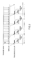
- FIG. 3 is a timing chart for explaining the operations of the respective units of the sensor unit 20 according to the first embodiment.
- the sensor unit starts the operation shown in this chart upon receiving a notification representing transition to the sleep state from a control unit 100. Note that the sensor unit may steadily operate independently of the state of the control unit 100.
- the acceleration sensor 201 steadily performs an operation of detecting an acceleration generated in the mobile wireless terminal apparatus and storing the detection result in the buffer unit 202a at a preset period t0. Note that when filled with detection results, the buffer unit 202a discards them in chronological order and stores the latest one instead.
- the state determination unit 203a reads out the detection results of the acceleration sensor 201 accumulated in the buffer unit 202a every time a period T (> t0) has elapsed. More specifically, the state determination unit 203a reads out, at the period T, the detection results of a plurality of samples accumulated in the buffer unit 202a during the period T.
- the state determination unit 203a determines the state of the mobile wireless terminal apparatus based on the readout detection results of the plurality of samples. Upon determining that the mobile wireless terminal apparatus is being held by the user who has, e.g., picked it up, the state determination unit 203a causes the control unit 100 to transit from the sleep state to the active state.
- the acceleration sensor 201 performs detection at the period t0, and the buffer unit 202a accumulates the detection results.
- the state determination unit 203a reads out the detection results from the buffer unit 202a at the period T longer than the period t0 and determines the state of the mobile wireless terminal apparatus.
- the state determination unit 203a performs determination at the period T longer than the detection period t0, instead of determining the detection result of the acceleration sensor 201 one by one. This reduces power consumption concerning determination without any degradation of detection accuracy, although the detection delays somewhat.
- FIG. 4 shows the arrangement of a sensor unit 20 according to the second embodiment of the present invention.
- the sensor unit 20 includes an acceleration sensor 201, a buffer unit 202a, a state determination unit 203b, and a user operation detection unit 204a.
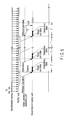
- FIG. 5 is a timing chart for explaining the operations of the respective units of the sensor unit 20 according to the second embodiment.
- the sensor unit starts the operation shown in this chart upon receiving a notification representing transition to the sleep state from a control unit 100. Note that the sensor unit may steadily operate independently of the state of the control unit 100.
- the acceleration sensor 201 steadily performs an operation of detecting an acceleration generated in the mobile wireless terminal apparatus and storing the detection result in the buffer unit 202a at a preset period t0. Note that when filled with detection results, the buffer unit 202a discards them in chronological order and stores the latest one instead.
- the user operation detection unit 204a monitors a user operation on an operation unit 50. When detecting a user operation, the user operation detection unit 204a notifies the state determination unit 203b of it. After receiving the notification representing that the user operation detection unit 204a has detected a user operation, the state determination unit 203b starts processing of reading out the detection results of the acceleration sensor 201 accumulated in the buffer unit 202a every time a period T (> t0) has elapsed. More specifically, the state determination unit 203b starts reading out, at the period T, the detection results of a plurality of samples accumulated in the buffer unit 202a during the period T.
- the state determination unit 203b may read out, upon receiving the notification from the user operation detection unit 204a, detection results accumulated in the buffer unit 202a at that point of time, and then read out the detection results of the acceleration sensor 201 accumulated in the buffer unit 202a every time the period T has elapsed.
- the state determination unit 203b determines the state of the mobile wireless terminal apparatus based on the readout detection results of the plurality of samples. Upon determining that the mobile wireless terminal apparatus is being held by the user who has, e.g., picked it up, the state determination unit 203b causes the control unit 100 to transit from the sleep state to the active state.
- FIG. 5 illustrates the time t1 shorter than the period T. However, the time t1 may be longer than the period T.
- the acceleration sensor 201 performs detection at the period t0, and the buffer unit 202a accumulates the detection results.
- the state determination unit 203b reads out the detection results from the buffer unit 202a at the period T longer than the period t0 and determines the state of the mobile wireless terminal apparatus.
- the state determination unit 203b performs determination at the period T longer than the detection period t0 only when a user operation is detected, instead of determining the detection result of the acceleration sensor 201 one by one. This further reduces power consumption concerning determination without any degradation of detection accuracy, although the detection delays somewhat.
- the state determination unit reads out the detection results of the acceleration sensor 201 which are accumulated in the buffer unit 202a until detection of a user operation, as shown in FIG. 5 .
- the state determination unit may read out the detection results of the acceleration sensor 201 which are accumulated in the buffer unit 202a after detection of a user operation, as shown in FIG. 6 .
- FIG. 7 shows the arrangement of a sensor unit 20 according to the third embodiment of the present invention.
- the sensor unit 20 includes an acceleration sensor 201, a buffer unit 202b, a state determination unit 203b, a user operation detection unit 204b, an illuminance sensor 205, and an unsteady state detection unit 206.
- FIG. 8 is a timing chart for explaining the operations of the respective units of the sensor unit 20 according to the third embodiment.
- the sensor unit starts the operation shown in this chart upon receiving a notification representing transition to the sleep state from a control unit 100. Note that the sensor unit may steadily operate independently of the state of the control unit 100.
- the acceleration sensor 201 steadily performs an operation of detecting an acceleration generated in the mobile wireless terminal apparatus and storing the detection result in the buffer unit 202b at a preset period t0. Note that when filled with detection results, the buffer unit 202b discards them in chronological order and stores the latest one instead.
- the illuminance sensor 205 detects the illuminance around the mobile wireless terminal apparatus and outputs the detection result to the unsteady state detection unit 206.
- the unsteady state detection unit 206 determines based on the detection result of the illuminance sensor 205 whether a preset state has been detected. For example, if a change of the ambient brightness has exceeded a preset level or more(or the ambient brightness has exceeded a preset brightness), the unsteady state detection unit 206 detects the change to an unsteady state. This aims at detecting, as an unsteady state, a user's extraction operation of, e.g., taking out the mobile wireless terminal apparatus from a bag.
- the user operation detection unit 204b monitors a user operation on an operation unit 50.
- the buffer unit 202b When the unsteady state detection unit 206 detects an unsteady state, the buffer unit 202b is controlled not to store the detection result of the acceleration sensor 201 during the detection of the unsteady state. More specifically, the unsteady state detection unit 206 instructs the buffer unit 202b to stop storing the detection result of the acceleration sensor 201. The buffer unit 202b thus stops storing the detection result of the acceleration sensor 201.
- the user operation detection unit 204b When detecting a user operation on the operation unit 50, the user operation detection unit 204b notifies the state determination unit 203b and the unsteady state detection unit 206 that a user operation has been performed.
- the buffer unit 202b stopped storing the detection result of the acceleration sensor 201 when the unsteady state detection unit 206 detected the unsteady state.
- the unsteady state detection unit 206 which has received the notification from the user operation detection unit 204b controls the buffer unit 202b to resume storing the detection result of the acceleration sensor 201. More specifically, the unsteady state detection unit 206 instructs the buffer unit 202b to resume storing the detection result of the acceleration sensor 201, and the buffer unit 202b resumes storing the detection result of the acceleration sensor 201.
- the state determination unit 203b upon receiving the notification from the user operation detection unit 204b, starts processing of reading out the detection results of the acceleration sensor 201 accumulated in the buffer unit 202b every time a period T (> t0) has elapsed. More specifically, the state determination unit 203b starts reading out, at the period T, the detection results of a plurality of samples accumulated in the buffer unit 202a during the period T.
- the state determination unit 203b when receiving the notification, the state determination unit 203b reads out the latest detection results accumulated in the buffer unit 202b at that point of time. After that, every time the period T has elapsed, the state determination unit 203b reads out the detection results of a plurality of samples accumulated in the buffer unit 202b during the period T. With this processing, the state determination unit 203b reads out the detection results immediately before the unsteady state detection unit 206 detects the unsteady state and subsequent detection results except during the time from the unsteady state detection by the unsteady state detection unit 206 to the user operation detection.
- the state determination unit 203b determines the state of the mobile wireless terminal apparatus based on the readout detection results of the plurality of samples. Upon determining that the mobile wireless terminal apparatus is being held by the user who has, e.g., picked it up, the state determination unit 203b causes the control unit 100 to transit from the sleep state to the active state.
- the state determination unit 203b reads out the detection results immediately before the change to the unsteady state and those after the user operation detection except during the time from the unsteady state detection by the unsteady state detection unit 206 to the user operation detection and determines the state of the mobile wireless terminal apparatus.
- the state determination unit 203b performs determination at the period T longer than the detection period t0 only when a user operation is detected, instead of determining the detection result of the acceleration sensor 201 one by one. This further reduces power consumption concerning determination without any degradation of detection accuracy, although the detection delays somewhat.
- the detection result of the acceleration sensor 201 in an unsteady state is not suitable for determining a state in which, for example, the user has extracted the mobile wireless terminal apparatus from a bag, and is therefore not used for state determination. This prevent determination errors.
- a mobile wireless terminal apparatus has been exemplified as a portable electronics.
- the present invention is not limited to this and is also applicable to a notebook personal computer, a PDA (Personal Digital Assistance), a portable game machine, a portable music player, a car navigation system, and the like.
Landscapes
- Engineering & Computer Science (AREA)
- Theoretical Computer Science (AREA)
- Physics & Mathematics (AREA)
- General Engineering & Computer Science (AREA)
- General Physics & Mathematics (AREA)
- Computer Networks & Wireless Communication (AREA)
- Signal Processing (AREA)
- Telephone Function (AREA)
- Mobile Radio Communication Systems (AREA)
- Power Sources (AREA)
Abstract
Description
- The present invention relates to a sensing method used in, e.g., a portable electronics.
- As is well known, an important challenge for portable electronics such as a cellular phone is to reduce power consumption. Conventionally, power consumption is reduced by detecting user's approach or contact and controlling the operating state in accordance with the user's approach, contact, or leaving (e.g., Jpn. Pat. Appln. KOKAI Publication No.
6-119090 - In such a conventional method, however, a sensor needs to always operate to detect user's approach or contact. This sensing consumes additional power.
- That is, in the conventional portable electronics, the power consumption of sensing poses a problem and is demanded to be lower.
- The present invention has been made in order to meet the above demand, and is intended to provide portable electronics capable of reducing power consumption required for sensing.
- To achieve this object, the present invention is a portable electronics comprising: a detection unit which detects a state of the portable electronics; a storage unit which stores a detection result of the detection unit at a first period; and a determination unit which reads out, every time a second period longer than the first period has elapsed, a plurality of detection results stored in the storage unit during the second period and determines the state of the portable electronics based on the plurality of readout detection results.
- In the present invention, the storage unit stores the detection result of the detection unit at the first period. A plurality of detection results stored in the storage unit during the second period longer than the first period are read out every time the second period has elapsed, and the state of the portable electronics is determined.
- The invention can be more fully understood from the following detailed description when taken in conjunction with the accompanying drawings, in which:
-
FIG. 1 is a block diagram showing the arrangement of a mobile wireless terminal apparatus using a sensing method according to the present invention; -
FIG. 2 is a block diagram showing the arrangement of a sensor unit of the mobile wireless terminal apparatus shown inFIG. 1 according to the first embodiment; -
FIG. 3 is a timing chart for explaining the operation of the sensor unit shown inFIG. 2 ; -
FIG. 4 is a block diagram showing the arrangement of a sensor unit of the mobile wireless terminal apparatus shown inFIG. 1 according to the second embodiment; -
FIG. 5 is a timing chart for explaining the operation of the sensor unit shown inFIG. 4 ; -
FIG. 6 is a timing chart for explaining the operation of the sensor unit shown inFIG. 4 ; -
FIG. 7 is a block diagram showing the arrangement of a sensor unit of the mobile wireless terminal apparatus shown inFIG. 1 according to the third embodiment; and -
FIG. 8 is a timing chart for explaining the operation of the sensor unit shown inFIG. 7 . - An embodiment of the present invention will now be described with reference to the accompanying drawing. A mobile wireless terminal apparatus such as a cellular phone will be explained below as an example of a portable electronics.
FIG. 1 is a block diagram showing the arrangement of a mobile wireless terminal apparatus according to the embodiment of the present invention. The mobile wireless terminal apparatus includes, as main constituent elements, acontrol unit 100, awireless communication unit 10, asensor unit 20, aspeech communication unit 30, adisplay unit 40, anoperation unit 50, and astorage unit 60, as shown inFIG. 1 . - The
wireless communication unit 10 complies with a wireless communication standard used in a mobile communication system such as W-CDMA (Wideband Code Division Multiple Access). Thewireless communication unit 10 wirelessly communicates with a base station apparatus BS accommodated in a mobile communication network NW in accordance with instructions from thecontrol unit 100 so as to transmit/receive voice data or email data or receive Web data or streaming data. That is, the mobile communication network NW and the base station apparatus BS accommodated in it form part of a cellular phone system. - The
sensor unit 20 detects the state of the mobile wireless terminal apparatus. In accordance with the detection result, thecontrol unit 100 transits from a sleep state to an active state. Note that the mobile wireless terminal apparatus can take, e.g., a standstill state when placed on a desk or the like, a held state when picked up from the desk by a user, and a carried state when carried by a user (e.g., moving on foot, moving by bicycle, moving by car, moving by train, or moving by airplane). - The
speech communication unit 30 is connected to aloudspeaker 31 and amicrophone 32. Thespeech communication unit 30 converts user's voice input via themicrophone 32 into voice data and outputs it to thecontrol unit 100. Alternatively, thespeech communication unit 30 decodes voice data received from a communication partner and outputs it via theloudspeaker 31. - The
display unit 40 displays an image (still or moving image) or text information to visually transfer information to the user under the control of thecontrol unit 100. - The
operation unit 50 includes a plurality of key switches and receives user instructions via them. - The
storage unit 60 stores, e.g., the control program and control data of thecontrol unit 100, application software, address data which associates the names, telephone numbers, and the like of communication partners with each other, data of sent and received email, Web data downloaded by Web browsing, and downloaded streaming data. - The
control unit 100 includes a microprocessor. Thecontrol unit 100 operates in accordance with the control program and control data stored in thestorage unit 60 to comprehensively control the units of the mobile wireless terminal apparatus and implement voice communication or data communication. Thecontrol unit 100 also has a communication control function of performing email transmission/reception, Web browsing, moving image display on thedisplay unit 40 based on downloaded streaming data, and voice communication by operating in accordance with application software stored in thestorage unit 60. - Without user operations from the
operation unit 50, mail reception, or incoming call for a predetermined time or more, thecontrol unit 100 transits from an active state that is a normal operating state to a sleep state in which the apparatus stops several functions, thereby suppressing power consumption. Upon receiving a request from thesensor unit 20 in the sleep state, thecontrol unit 100 transits to the active state again. - The
control unit 100 executes various kinds of control based on information representing the state of the mobile wireless terminal apparatus sent from thesensor unit 20. -
FIG. 2 shows the arrangement of asensor unit 20 according to the first embodiment of the present invention. Thesensor unit 20 includes anacceleration sensor 201, abuffer unit 202a, and astate determination unit 203a.FIG. 3 is a timing chart for explaining the operations of the respective units of thesensor unit 20 according to the first embodiment. The sensor unit starts the operation shown in this chart upon receiving a notification representing transition to the sleep state from acontrol unit 100. Note that the sensor unit may steadily operate independently of the state of thecontrol unit 100. - The operations of the units will be described below with reference to
FIG. 3 . - The
acceleration sensor 201 steadily performs an operation of detecting an acceleration generated in the mobile wireless terminal apparatus and storing the detection result in thebuffer unit 202a at a preset period t0. Note that when filled with detection results, thebuffer unit 202a discards them in chronological order and stores the latest one instead. - The
state determination unit 203a reads out the detection results of theacceleration sensor 201 accumulated in thebuffer unit 202a every time a period T (> t0) has elapsed. More specifically, thestate determination unit 203a reads out, at the period T, the detection results of a plurality of samples accumulated in thebuffer unit 202a during the period T. - The
state determination unit 203a determines the state of the mobile wireless terminal apparatus based on the readout detection results of the plurality of samples. Upon determining that the mobile wireless terminal apparatus is being held by the user who has, e.g., picked it up, thestate determination unit 203a causes thecontrol unit 100 to transit from the sleep state to the active state. - As described above, in the mobile wireless terminal apparatus having the above arrangement, the
acceleration sensor 201 performs detection at the period t0, and thebuffer unit 202a accumulates the detection results. Thestate determination unit 203a reads out the detection results from thebuffer unit 202a at the period T longer than the period t0 and determines the state of the mobile wireless terminal apparatus. - According to the mobile wireless terminal apparatus with the above arrangement, the
state determination unit 203a performs determination at the period T longer than the detection period t0, instead of determining the detection result of theacceleration sensor 201 one by one. This reduces power consumption concerning determination without any degradation of detection accuracy, although the detection delays somewhat. -
FIG. 4 shows the arrangement of asensor unit 20 according to the second embodiment of the present invention. Thesensor unit 20 includes anacceleration sensor 201, abuffer unit 202a, astate determination unit 203b, and a useroperation detection unit 204a.FIG. 5 is a timing chart for explaining the operations of the respective units of thesensor unit 20 according to the second embodiment. The sensor unit starts the operation shown in this chart upon receiving a notification representing transition to the sleep state from acontrol unit 100. Note that the sensor unit may steadily operate independently of the state of thecontrol unit 100. - The operations of the units will be described below with reference to
FIG. 5 . - The
acceleration sensor 201 steadily performs an operation of detecting an acceleration generated in the mobile wireless terminal apparatus and storing the detection result in thebuffer unit 202a at a preset period t0. Note that when filled with detection results, thebuffer unit 202a discards them in chronological order and stores the latest one instead. - The user
operation detection unit 204a monitors a user operation on anoperation unit 50. When detecting a user operation, the useroperation detection unit 204a notifies thestate determination unit 203b of it. After receiving the notification representing that the useroperation detection unit 204a has detected a user operation, thestate determination unit 203b starts processing of reading out the detection results of theacceleration sensor 201 accumulated in thebuffer unit 202a every time a period T (> t0) has elapsed. More specifically, thestate determination unit 203b starts reading out, at the period T, the detection results of a plurality of samples accumulated in thebuffer unit 202a during the period T. - Note that the
state determination unit 203b may read out, upon receiving the notification from the useroperation detection unit 204a, detection results accumulated in thebuffer unit 202a at that point of time, and then read out the detection results of theacceleration sensor 201 accumulated in thebuffer unit 202a every time the period T has elapsed. - The
state determination unit 203b determines the state of the mobile wireless terminal apparatus based on the readout detection results of the plurality of samples. Upon determining that the mobile wireless terminal apparatus is being held by the user who has, e.g., picked it up, thestate determination unit 203b causes thecontrol unit 100 to transit from the sleep state to the active state. - After that, upon detecting a state without user operations has continued for a time t1 or more, the user
operation detection unit 204a notifies thestate determination unit 203b of it. Then, thestate determination unit 203b stops the processing of reading out the detection results from thebuffer unit 202a.FIG. 5 illustrates the time t1 shorter than the period T. However, the time t1 may be longer than the period T. - As described above, in the mobile wireless terminal apparatus having the above arrangement, the
acceleration sensor 201 performs detection at the period t0, and thebuffer unit 202a accumulates the detection results. When a user operation is detected, thestate determination unit 203b reads out the detection results from thebuffer unit 202a at the period T longer than the period t0 and determines the state of the mobile wireless terminal apparatus. - According to the mobile wireless terminal apparatus with the above arrangement, the
state determination unit 203b performs determination at the period T longer than the detection period t0 only when a user operation is detected, instead of determining the detection result of theacceleration sensor 201 one by one. This further reduces power consumption concerning determination without any degradation of detection accuracy, although the detection delays somewhat. - Note that in the second embodiment, the state determination unit reads out the detection results of the
acceleration sensor 201 which are accumulated in thebuffer unit 202a until detection of a user operation, as shown inFIG. 5 . However, the state determination unit may read out the detection results of theacceleration sensor 201 which are accumulated in thebuffer unit 202a after detection of a user operation, as shown inFIG. 6 . -
FIG. 7 shows the arrangement of asensor unit 20 according to the third embodiment of the present invention. Thesensor unit 20 includes anacceleration sensor 201, abuffer unit 202b, astate determination unit 203b, a useroperation detection unit 204b, anilluminance sensor 205, and an unsteadystate detection unit 206.FIG. 8 is a timing chart for explaining the operations of the respective units of thesensor unit 20 according to the third embodiment. The sensor unit starts the operation shown in this chart upon receiving a notification representing transition to the sleep state from acontrol unit 100. Note that the sensor unit may steadily operate independently of the state of thecontrol unit 100. - The operations of the units will be described below with reference to
FIG. 8 . - The
acceleration sensor 201 steadily performs an operation of detecting an acceleration generated in the mobile wireless terminal apparatus and storing the detection result in thebuffer unit 202b at a preset period t0. Note that when filled with detection results, thebuffer unit 202b discards them in chronological order and stores the latest one instead. - The
illuminance sensor 205 detects the illuminance around the mobile wireless terminal apparatus and outputs the detection result to the unsteadystate detection unit 206. The unsteadystate detection unit 206 determines based on the detection result of theilluminance sensor 205 whether a preset state has been detected. For example, if a change of the ambient brightness has exceeded a preset level or more(or the ambient brightness has exceeded a preset brightness), the unsteadystate detection unit 206 detects the change to an unsteady state. This aims at detecting, as an unsteady state, a user's extraction operation of, e.g., taking out the mobile wireless terminal apparatus from a bag. The useroperation detection unit 204b monitors a user operation on anoperation unit 50. - When the unsteady
state detection unit 206 detects an unsteady state, thebuffer unit 202b is controlled not to store the detection result of theacceleration sensor 201 during the detection of the unsteady state. More specifically, the unsteadystate detection unit 206 instructs thebuffer unit 202b to stop storing the detection result of theacceleration sensor 201. Thebuffer unit 202b thus stops storing the detection result of theacceleration sensor 201. - When detecting a user operation on the
operation unit 50, the useroperation detection unit 204b notifies thestate determination unit 203b and the unsteadystate detection unit 206 that a user operation has been performed. Thebuffer unit 202b stopped storing the detection result of theacceleration sensor 201 when the unsteadystate detection unit 206 detected the unsteady state. Hence, the unsteadystate detection unit 206 which has received the notification from the useroperation detection unit 204b controls thebuffer unit 202b to resume storing the detection result of theacceleration sensor 201. More specifically, the unsteadystate detection unit 206 instructs thebuffer unit 202b to resume storing the detection result of theacceleration sensor 201, and thebuffer unit 202b resumes storing the detection result of theacceleration sensor 201. - On the other hand, upon receiving the notification from the user
operation detection unit 204b, thestate determination unit 203b starts processing of reading out the detection results of theacceleration sensor 201 accumulated in thebuffer unit 202b every time a period T (> t0) has elapsed. More specifically, thestate determination unit 203b starts reading out, at the period T, the detection results of a plurality of samples accumulated in thebuffer unit 202a during the period T. - Note that when receiving the notification, the
state determination unit 203b reads out the latest detection results accumulated in thebuffer unit 202b at that point of time. After that, every time the period T has elapsed, thestate determination unit 203b reads out the detection results of a plurality of samples accumulated in thebuffer unit 202b during the period T. With this processing, thestate determination unit 203b reads out the detection results immediately before the unsteadystate detection unit 206 detects the unsteady state and subsequent detection results except during the time from the unsteady state detection by the unsteadystate detection unit 206 to the user operation detection. - The
state determination unit 203b determines the state of the mobile wireless terminal apparatus based on the readout detection results of the plurality of samples. Upon determining that the mobile wireless terminal apparatus is being held by the user who has, e.g., picked it up, thestate determination unit 203b causes thecontrol unit 100 to transit from the sleep state to the active state. - As described above, in the mobile wireless terminal apparatus having the above arrangement, the
state determination unit 203b reads out the detection results immediately before the change to the unsteady state and those after the user operation detection except during the time from the unsteady state detection by the unsteadystate detection unit 206 to the user operation detection and determines the state of the mobile wireless terminal apparatus. - According to the mobile wireless terminal apparatus with the above arrangement, the
state determination unit 203b performs determination at the period T longer than the detection period t0 only when a user operation is detected, instead of determining the detection result of theacceleration sensor 201 one by one. This further reduces power consumption concerning determination without any degradation of detection accuracy, although the detection delays somewhat. - Additionally, the detection result of the
acceleration sensor 201 in an unsteady state is not suitable for determining a state in which, for example, the user has extracted the mobile wireless terminal apparatus from a bag, and is therefore not used for state determination. This prevent determination errors. - Note that the present invention is not directly limited to the above embodiments, and constituent elements can be modified in the stage of practice without departing from the spirit and scope of the invention. Various inventions can be formed by properly combining a plurality of constituent elements disclosed in the above embodiments. For example, several constituent elements may be omitted from all the constituent elements described in the embodiments. In addition, constituent elements throughout different embodiments may be properly combined.
- For example, in the above embodiments, a mobile wireless terminal apparatus has been exemplified as a portable electronics. However, the present invention is not limited to this and is also applicable to a notebook personal computer, a PDA (Personal Digital Assistance), a portable game machine, a portable music player, a car navigation system, and the like.
- Various changes and modifications can also be made within the spirit and scope of the present invention.
Claims (18)
- A portable electronics characterized by comprising:a detection unit (201) which detects a state of the portable electronics;a storage unit (202a, 202b) which stores a detection result of the detection unit at a first period; anda determination unit (203a, 203b) which reads out, every time a second period longer than the first period has elapsed, a plurality of detection results stored in the storage unit during the second period and determines the state of the portable electronics based on the plurality of readout detection results.
- The portable electronics according to claim 1, characterized by further comprising:an input unit (50) which receives a request from a user; anda request detection unit (204a, 204b) which detects input of the request to the input unit,wherein when the request detection unit has detected the input of the request, the determination unit reads out, every time the second period has elapsed, the plurality of detection results stored in the storage unit during the second period and determines the state of the portable electronics based on the plurality of readout detection results.
- The portable electronics according to claim 2, characterized in that the determination unit determines the state of the portable electronics based on detection results which are stored in the storage unit until the request detection unit has detected the input of the request.
- The portable electronics according to claim 2, characterized in that the determination unit determines the state of the portable electronics based on detection results which are stored in the storage unit after the request detection unit has detected the input of the request.
- The portable electronics according to claim 2, characterized by further comprising an ambient state detection unit (205a) which detects a state around the portable electronics,
wherein the storage unit stores, at the first period, a plurality of detection results except detection results detected by the detection unit during detection of a preset state by the ambient state detection unit. - The portable electronics according to claim 1, characterized in that the detection unit detects an acceleration generated in the portable electronics.
- The portable electronics according to claim 1, characterized by further comprising a switching unit (203a, 203b) which switches an operating state of a control unit controlling the portable electronics from a sleep state to an active state or from the active state to the sleep state in accordance with a determination result of the determination unit.
- The portable electronics according to claim 1, characterized by further comprising a switching unit (203a, 203b) which switches an operating state of the portable electronics from a high power consumption state to a low power consumption state or from the low power consumption state to the high power consumption state in accordance with a determination result of the determination unit.
- The portable electronics according to claim 1, characterized by further comprising a switching unit (203a, 203b) which switches several functions of the portable electronics from an operating state to a stop state or from the stop state to the operating state in accordance with a determination result of the determination unit.
- A sensing method characterized by comprising:a detection step (201) of detecting a state of the portable electronics;a storage step (202a, 202b) of causing a storage unit to store a detection result in the detection step at a first period; anda determination step (203a, 203b) of reading out, every time a second period longer than the first period has elapsed, a plurality of detection results stored in the storage unit during the second period and determining the state of the portable electronics based on the plurality of readout detection results.
- The sensing method according to claim 10, characterized by further comprising a request detection step (204a, 204b) of detecting input of a request to an input unit which receives a request from a user,
wherein in the determination step, when the input of the request has been detected in the request detection step, the plurality of detection results stored in the storage unit during the second period are read out every time the second period has elapsed, and the state of the portable electronics is determined based on the plurality of readout detection results. - The sensing method according to claim 11, characterized in that in the determination step, the state of the portable electronics is determined based on detection results which are stored in the storage unit until the input of the request has been detected in the request detection step.
- The sensing method according to claim 11, characterized in that in the determination step, the state of the portable electronics is determined based on detection results which are stored in the storage unit after the input of the request has been detected in the request detection step.
- The sensing method according to claim 11, characterized by further comprising an ambient state detection step (205a) of detecting a state around the portable electronics,
wherein in the storage step, the storage unit stores, at the first period, a plurality of detection results except detection results detected in the detection step during detection of a preset state in the ambient state detection step. - The sensing method according to claim 10, characterized in that in the detection step, an acceleration generated in the portable electronics is detected.
- The sensing method according to claim 10, characterized by further comprising a switching step (203a, 203b) of switching an operating state of a control unit controlling the portable electronics from a sleep state to an active state or from the active state to the sleep state in accordance with a determination result in the determination step.
- The sensing method according to claim 10, characterized by further comprising a switching step (203a, 203b) of switching an operating state of the portable electronics from a high power consumption state to a low power consumption state or from the low power consumption state to the high power consumption state in accordance with a determination result in the determination step.
- The sensing method according to claim 10, characterized by further comprising a switching step (203a, 203b) of switching several functions of the portable electronics from an operating state to a stop state or from the stop state to the operating state in accordance with a determination result in the determination step.
Applications Claiming Priority (1)
| Application Number | Priority Date | Filing Date | Title |
|---|---|---|---|
| JP2008192530A JP2010033174A (en) | 2008-07-25 | 2008-07-25 | Portable electronic device |
Publications (1)
| Publication Number | Publication Date |
|---|---|
| EP2149834A2 true EP2149834A2 (en) | 2010-02-03 |
Family
ID=41226692
Family Applications (1)
| Application Number | Title | Priority Date | Filing Date |
|---|---|---|---|
| EP09009625A Withdrawn EP2149834A2 (en) | 2008-07-25 | 2009-07-24 | Portable electronics and sensing method |
Country Status (3)
| Country | Link |
|---|---|
| US (1) | US20100039276A1 (en) |
| EP (1) | EP2149834A2 (en) |
| JP (1) | JP2010033174A (en) |
Cited By (1)
| Publication number | Priority date | Publication date | Assignee | Title |
|---|---|---|---|---|
| WO2013052874A1 (en) * | 2011-10-06 | 2013-04-11 | Qualcomm Incorporated | Method and apparatus for advanced motion detection in wireless communications systems |
Families Citing this family (1)
| Publication number | Priority date | Publication date | Assignee | Title |
|---|---|---|---|---|
| US20160295514A1 (en) * | 2013-03-22 | 2016-10-06 | Nec Corporation | Information terminal, movement estimation method, and storage medium |
Family Cites Families (7)
| Publication number | Priority date | Publication date | Assignee | Title |
|---|---|---|---|---|
| US5959529A (en) * | 1997-03-07 | 1999-09-28 | Kail, Iv; Karl A. | Reprogrammable remote sensor monitoring system |
| JP3757175B2 (en) * | 2002-02-21 | 2006-03-22 | 日本電気通信システム株式会社 | Mobile phone, control method therefor, and program |
| EP1738566A4 (en) * | 2004-08-09 | 2012-11-14 | Rpx Corp | METHOD FOR COLLECTING MEASUREMENT DATA AND PORTABLE INFORMATION DEVICE |
| JP4382703B2 (en) * | 2005-06-07 | 2009-12-16 | 埼玉日本電気株式会社 | Mobile phone having non-contact IC card function and control method thereof |
| JP2007080219A (en) * | 2005-09-16 | 2007-03-29 | Navitime Japan Co Ltd | Mobile terminal and power saving control method in the same |
| US8996332B2 (en) * | 2008-06-24 | 2015-03-31 | Dp Technologies, Inc. | Program setting adjustments based on activity identification |
| US8172722B2 (en) * | 2008-12-05 | 2012-05-08 | Nike, Inc. | Athletic performance monitoring systems and methods in a team sports environment |
-
2008
- 2008-07-25 JP JP2008192530A patent/JP2010033174A/en active Pending
-
2009
- 2009-07-23 US US12/508,123 patent/US20100039276A1/en active Granted
- 2009-07-24 EP EP09009625A patent/EP2149834A2/en not_active Withdrawn
Cited By (2)
| Publication number | Priority date | Publication date | Assignee | Title |
|---|---|---|---|---|
| WO2013052874A1 (en) * | 2011-10-06 | 2013-04-11 | Qualcomm Incorporated | Method and apparatus for advanced motion detection in wireless communications systems |
| WO2013052871A1 (en) * | 2011-10-06 | 2013-04-11 | Qualcomm Incorporated | Method and apparatus for optimized reacquisition of wireless communications systems |
Also Published As
| Publication number | Publication date |
|---|---|
| US20100039276A1 (en) | 2010-02-18 |
| JP2010033174A (en) | 2010-02-12 |
Similar Documents
| Publication | Publication Date | Title |
|---|---|---|
| CN102017728B (en) | Method of optimizing power consumption in a wireless device | |
| US9620126B2 (en) | Electronic device, control method, and control program | |
| CN108259975B (en) | Video playing method, storage medium and terminal | |
| US10818246B2 (en) | Context sensitive backlight | |
| CN107888768B (en) | Unlocking control method, terminal and computer readable storage medium | |
| US20150009284A1 (en) | Method and device for video processing | |
| US20100295790A1 (en) | Apparatus and method for display switching in a portable terminal | |
| US9141206B2 (en) | Apparatus and method for motion detection in portable terminal | |
| US8135381B2 (en) | Mobile apparatus | |
| CN108898552B (en) | Picture splicing method, double-screen terminal and computer readable storage medium | |
| WO2015043505A1 (en) | Method, apparatus, and system for sending and receiving social network information | |
| CN106646440B (en) | Method and device for detecting drop height | |
| US9344541B2 (en) | Call connection method and apparatus in mobile terminal | |
| CN110096375B (en) | Method and device for sharing data by application programs and computer readable storage medium | |
| US10136115B2 (en) | Video shooting method and apparatus | |
| US20100039276A1 (en) | Portable electronics and sensing method | |
| CN109151201B (en) | Anti-addiction method, mobile terminal and computer storage medium | |
| JP2006319420A (en) | Mobile radio terminal device | |
| CN107528770B (en) | Display method, terminal and computer storage medium | |
| US10225388B2 (en) | Method and apparatus for adjusting volume of an accepted session | |
| CN110572518B (en) | Screen-extinguishing control method, mobile terminal and computer-readable storage medium | |
| CN110048900B (en) | Log management method, mobile terminal and computer readable storage medium | |
| CN112487327B (en) | E-book loading method and device and mobile terminal | |
| KR20210016466A (en) | PDSCH time domain resource distribution method, terminal and computer-readable storage medium | |
| CN112468870A (en) | Video playing method, device, equipment and storage medium |
Legal Events
| Date | Code | Title | Description |
|---|---|---|---|
| PUAI | Public reference made under article 153(3) epc to a published international application that has entered the european phase |
Free format text: ORIGINAL CODE: 0009012 |
|
| 17P | Request for examination filed |
Effective date: 20090724 |
|
| AK | Designated contracting states |
Kind code of ref document: A2 Designated state(s): AT BE BG CH CY CZ DE DK EE ES FI FR GB GR HR HU IE IS IT LI LT LU LV MC MK MT NL NO PL PT RO SE SI SK SM TR |
|
| AX | Request for extension of the european patent |
Extension state: AL BA RS |
|
| RAP1 | Party data changed (applicant data changed or rights of an application transferred) |
Owner name: FUJITSU TOSHIBA MOBILE COMMUNICATIONS LIMITED |
|
| RAP1 | Party data changed (applicant data changed or rights of an application transferred) |
Owner name: FUJITSU MOBILE COMMUNICATIONS LIMITED |
|
| STAA | Information on the status of an ep patent application or granted ep patent |
Free format text: STATUS: THE APPLICATION HAS BEEN WITHDRAWN |
|
| 18W | Application withdrawn |
Effective date: 20130723 |