EP2149741A1 - Lighting apparatus, display apparatus and tv receiver - Google Patents
Lighting apparatus, display apparatus and tv receiver Download PDFInfo
- Publication number
- EP2149741A1 EP2149741A1 EP08710560A EP08710560A EP2149741A1 EP 2149741 A1 EP2149741 A1 EP 2149741A1 EP 08710560 A EP08710560 A EP 08710560A EP 08710560 A EP08710560 A EP 08710560A EP 2149741 A1 EP2149741 A1 EP 2149741A1
- Authority
- EP
- European Patent Office
- Prior art keywords
- diffusion
- protective member
- lighting apparatus
- light source
- supporting pin
- Prior art date
- Legal status (The legal status is an assumption and is not a legal conclusion. Google has not performed a legal analysis and makes no representation as to the accuracy of the status listed.)
- Granted
Links
Images


Classifications
-
- G—PHYSICS
- G02—OPTICS
- G02F—OPTICAL DEVICES OR ARRANGEMENTS FOR THE CONTROL OF LIGHT BY MODIFICATION OF THE OPTICAL PROPERTIES OF THE MEDIA OF THE ELEMENTS INVOLVED THEREIN; NON-LINEAR OPTICS; FREQUENCY-CHANGING OF LIGHT; OPTICAL LOGIC ELEMENTS; OPTICAL ANALOGUE/DIGITAL CONVERTERS
- G02F1/00—Devices or arrangements for the control of the intensity, colour, phase, polarisation or direction of light arriving from an independent light source, e.g. switching, gating or modulating; Non-linear optics
- G02F1/01—Devices or arrangements for the control of the intensity, colour, phase, polarisation or direction of light arriving from an independent light source, e.g. switching, gating or modulating; Non-linear optics for the control of the intensity, phase, polarisation or colour
- G02F1/13—Devices or arrangements for the control of the intensity, colour, phase, polarisation or direction of light arriving from an independent light source, e.g. switching, gating or modulating; Non-linear optics for the control of the intensity, phase, polarisation or colour based on liquid crystals, e.g. single liquid crystal display cells
- G02F1/133—Constructional arrangements; Operation of liquid crystal cells; Circuit arrangements
- G02F1/1333—Constructional arrangements; Manufacturing methods
- G02F1/1335—Structural association of cells with optical devices, e.g. polarisers or reflectors
- G02F1/1336—Illuminating devices
- G02F1/133602—Direct backlight
- G02F1/133608—Direct backlight including particular frames or supporting means
-
- G—PHYSICS
- G02—OPTICS
- G02F—OPTICAL DEVICES OR ARRANGEMENTS FOR THE CONTROL OF LIGHT BY MODIFICATION OF THE OPTICAL PROPERTIES OF THE MEDIA OF THE ELEMENTS INVOLVED THEREIN; NON-LINEAR OPTICS; FREQUENCY-CHANGING OF LIGHT; OPTICAL LOGIC ELEMENTS; OPTICAL ANALOGUE/DIGITAL CONVERTERS
- G02F1/00—Devices or arrangements for the control of the intensity, colour, phase, polarisation or direction of light arriving from an independent light source, e.g. switching, gating or modulating; Non-linear optics
- G02F1/01—Devices or arrangements for the control of the intensity, colour, phase, polarisation or direction of light arriving from an independent light source, e.g. switching, gating or modulating; Non-linear optics for the control of the intensity, phase, polarisation or colour
- G02F1/13—Devices or arrangements for the control of the intensity, colour, phase, polarisation or direction of light arriving from an independent light source, e.g. switching, gating or modulating; Non-linear optics for the control of the intensity, phase, polarisation or colour based on liquid crystals, e.g. single liquid crystal display cells
- G02F1/133—Constructional arrangements; Operation of liquid crystal cells; Circuit arrangements
- G02F1/1333—Constructional arrangements; Manufacturing methods
- G02F1/1335—Structural association of cells with optical devices, e.g. polarisers or reflectors
- G02F1/1336—Illuminating devices
- G02F1/133602—Direct backlight
- G02F1/133604—Direct backlight with lamps
-
- G—PHYSICS
- G02—OPTICS
- G02F—OPTICAL DEVICES OR ARRANGEMENTS FOR THE CONTROL OF LIGHT BY MODIFICATION OF THE OPTICAL PROPERTIES OF THE MEDIA OF THE ELEMENTS INVOLVED THEREIN; NON-LINEAR OPTICS; FREQUENCY-CHANGING OF LIGHT; OPTICAL LOGIC ELEMENTS; OPTICAL ANALOGUE/DIGITAL CONVERTERS
- G02F1/00—Devices or arrangements for the control of the intensity, colour, phase, polarisation or direction of light arriving from an independent light source, e.g. switching, gating or modulating; Non-linear optics
- G02F1/01—Devices or arrangements for the control of the intensity, colour, phase, polarisation or direction of light arriving from an independent light source, e.g. switching, gating or modulating; Non-linear optics for the control of the intensity, phase, polarisation or colour
- G02F1/13—Devices or arrangements for the control of the intensity, colour, phase, polarisation or direction of light arriving from an independent light source, e.g. switching, gating or modulating; Non-linear optics for the control of the intensity, phase, polarisation or colour based on liquid crystals, e.g. single liquid crystal display cells
- G02F1/133—Constructional arrangements; Operation of liquid crystal cells; Circuit arrangements
- G02F1/1333—Constructional arrangements; Manufacturing methods
- G02F1/1335—Structural association of cells with optical devices, e.g. polarisers or reflectors
- G02F1/1336—Illuminating devices
- G02F1/133602—Direct backlight
- G02F1/133611—Direct backlight including means for improving the brightness uniformity
-
- G—PHYSICS
- G02—OPTICS
- G02F—OPTICAL DEVICES OR ARRANGEMENTS FOR THE CONTROL OF LIGHT BY MODIFICATION OF THE OPTICAL PROPERTIES OF THE MEDIA OF THE ELEMENTS INVOLVED THEREIN; NON-LINEAR OPTICS; FREQUENCY-CHANGING OF LIGHT; OPTICAL LOGIC ELEMENTS; OPTICAL ANALOGUE/DIGITAL CONVERTERS
- G02F2201/00—Constructional arrangements not provided for in groups G02F1/00 - G02F7/00
- G02F2201/50—Protective arrangements
- G02F2201/503—Arrangements improving the resistance to shock
Definitions
- the present invention relates to a lighting apparatus that illuminates a display panel such as a liquid crystal panel, and to a display apparatus and a television receiver employing such a lighting apparatus.
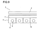
- FIG. 9 is a side sectional view schematically showing the display apparatus.
- the display apparatus 1 has a lighting apparatus 3 that faces a display panel 2.
- the lighting apparatus 3 is provided with a back chassis 4 - formed of metal -, which is open at the display panel 2-side and covers the rear side of the lighting apparatus 3.
- a plurality of light sources 5 comprising long-length fluorescent tubes are arranged side by side.
- a diffusion plate 7 facing the light sources 5 is disposed.
- the diffusion plate 7 has its periphery held by the back chassis 4 and diffuses light emitted from the light sources 5 so as to make light for illuminating the display panel 2 uniform.
- the diffusion plate 7 is supported by diffusion-plate supporting pins 10 having a sharp point, which are fitted to the back chassis 4.
- the diffusion-plate supporting pins 10 As the diffusion-plate supporting pins 10, a plurality of them are provided between the light sources 5 so that the diffusion plate 7 and the light sources 5 are kept apart. This prevents the light sources 5 reflected in display images, which is caused by the diffusion plate 7 being thermally deformed by the heat from the light sources 5 and coming closer to the light sources 5.
- Patent Document 1 JP-A-2005-347005 (pages 4 to 9, Fig. 2 )
- the light sources 5 may disadvantageously collide with the diffusion-plate supporting pins 10 and brake when shock acts on the display apparatus 1 during transportation etc.
- the light sources 5 are likely to collide with the diffusion-plate supporting pins 10 due to deflection caused by their own weight.
- An object of the present invention is to provide a lighting apparatus in which breakage of a light source can be prevented, and to provide a display apparatus and a television receiver that employ such a lighting apparatus.
- a lighting apparatus comprises: a back chassis covering the rear side of the lighting apparatus; a light source comprising a fluorescent tube held on the back chassis, the fluorescent tube having parts extending in one direction arranged side by side in a direction perpendicular to the direction of extension; a diffusion plate arranged to face the light source to diffuse light emitted from the light source; a diffusion-plate supporting pin arranged upright between adjacent parts of the light source to support the diffusion plate; and a protective member arranged around the diffusion-plate supporting pin and formed of a shock absorbing material absorbing shock by elasticity.
- the back chassis covers the rear side of the lighting apparatus and holds the light source comprising a fluorescent tube.
- the light source comprising a plurality of fluorescent tubes or a meandering fluorescent tube that, preferably, has parts extending horizontally to be arranged side by side in the vertical direction.
- the diffusion-plate supporting pin that is fitted to the back chassis is arranged, and the diffusion plate facing the light source makes contact with the diffusion-plate supporting pin to be supported thereby.
- the diffusion-plate supporting pin is provided with the protective member that covers around it.
- the protective member is formed of a shock absorbing material such as resin or rubber, and absorbs shock when the light source collides with it.
- a projection is provided on the circumferential surface of the diffusion-plate supporting pin, and the protective member through which the diffusion-plate supporting pin is inserted has its diffusion plate-side locked by the projection.
- the tubular protective member is put on the diffusion-plate supporting pin from its tip. Passing the projection, the protective member is arranged on the base side of the projection, and has its diffusion plate-side locked by the projection so that it does not come off.
- the outer circumference surface of the diffusion-plate supporting pin is formed to have a taper shape
- the inner circumference surface of the protective member through which the diffusion-plate supporting pin is inserted is formed to have a taper shape.
- a concave part and a convex part are formed at the outer circumference surface of the protective member through which the diffusion-plate supporting pin is inserted.
- parts of the light source extend in the horizontal direction arranged side by side in the vertical direction.
- the protective member is formed to be transparent, white/whitish, or gray/grayish.
- the protective member is formed of microcell polymer.
- the protective member is formed of microcell polymer, which is a shock absorbing material such as PORON (manufactured by Rogers Inoac Corporation).
- the protective member is formed of foamed polyethylene.
- the protective member is formed of rubber sponge.
- the protective member is formed of silicon-based gel.
- the display apparatus comprises the lighting apparatus arranged as described above and the display panel that faces the diffusion plate.
- the display panel is built with a liquid crystal panel having a pair of substrates with liquid crystal sealed in between.
- a television receiver comprises the display apparatus arranged as described above.
- the protective member arranged around the diffusion-plate supporting pin that supports the diffusion plate is formed of a shock absorbing material; thus, it is possible to prevent breakage of the light source caused by the light source colliding with the diffusion-plate supporting pin when shock acts on the lighting apparatus.
- the protective member through which the diffusion-plate supporting pin is inserted is locked by the projection provided on the circumference surface of the diffusion-plate supporting pin; thus, the protective member can be easily prevented from coming off.
- the outer circumferential surface of the diffusion-plate supporting pin and the inner circumferential surface of the protective member are formed to have a taper shape; thus, the protective member can be positioned easily in the height direction. Moreover, the area increases where the diffusion-plate supporting pin is in contact with the protective member, and, by friction, the protective member can be easily prevented from coming off.
- a concave part and a convex part are formed at the outer circumferential surface of the protective member, making it easy to hold the protective member with fingers. Accordingly, it is possible to improve workability when putting the protective member on the diffusion-plate supporting pin.
- the light source is likely to collide with the diffusion-plate supporting pin due to its own weight, since parts of the light source extend in the horizontal direction arranged side by side in the vertical direction, it is possible to surely prevent breakage of the light source caused by collision.
- the protective member is formed to be transparent, white/whitish, or gray/grayish; thus, it is possible to prevent degraded image quality caused by the protective member reflected in the display panel.
- the protective member is formed of microcell polymer; thus, it is possible to easily realize a protective member absorbing shock.
- the protective member is formed of foamed polyethylene; thus, it is possible to easily realize a protective member absorbing shock.
- the protective member is formed of rubber sponge; thus, it is possible to easily realize a protective member absorbing shock.
- the protective member is formed of silicon-based gel; thus, it is possible to easily realize a protective member absorbing shock.
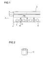
- FIG. 1 is a side sectional view showing a display apparatus according to one embodiment.
- a display apparatus 1 such as a television receiver or a display, has a lighting apparatus 3 arranged at the back of a display panel 2.
- the display panel 2 is built with a liquid crystal panel or the like that has a pair of substrates with liquid crystal sealed in between.
- the display panel 2 has pixels arranged in a matrix, and light emitted from the lighting apparatus 3 transmits a predetermined pixel of the display panel 2 so that images are displayed.
- the lighting apparatus 3 is provided with a back chassis 4 - formed of metal -, which is open at its front and covers the rear side of the lighting apparatus 3.
- a back chassis 4 - formed of metal -, which is open at its front and covers the rear side of the lighting apparatus 3.
- the back chassis 4 By forming the back chassis 4 with metal, it is possible to obtain a desired strength with a decreased thickness thereof, and thus to achieve a compact lighting apparatus 3.
- a light source 5 is disposed inside the back chassis 4.
- the light source 5 comprises a plurality of cylindrical fluorescent tubes having parts extending in one direction arranged at a predetermined interval (period) in the direction perpendicular to the direction of extension.
- the light source 5 may be arranged side by side at a predetermined interval by composing them with one or more meandering fluorescent tubes.
- the diffusion plate 7 is formed of a plate-like transmissive member holding a diffusion member, and diffuses light emitted from the light source 5.
- the diffusion plate 7 has its peripheral portion held by the back chassis 4, and is supported by a diffusion-plate supporting pin 10 fitted to the back chassis 4.
- the diffusion-plate supporting pin 10 is formed out of a conical resin component having a sharp point, and is fitted to, with a claw portion (unillustrated) at its back engaged with, the back chassis 4.
- a plurality of them are provided between parts of the light source 5 having a plurality of fluorescent tubes or a meandering fluorescent tube arranged side by side, so that the diffusion plate 7 and the light source 5 are kept apart. In this way, it is possible to prevent the light source 5 reflected in display images, which is caused by the diffusion plate 7 being thermally deformed by the heat from the light source 5 and coming close to the light source 5.
- a protective member 11 is arranged around the diffusion-plate supporting pin 10, a protective member 11 is arranged.
- Fig. 2 is a perspective view showing the protective member 11.
- the protective member 11 is formed into a tubular shape and, as described in detail below, is formed of a shock-absorbing material absorbing shock by elasticity.
- a projection 10a that projects in the radius direction is provided on the circumferential surface of the diffusion-plate supporting pin 10.
- the tubular protective member 11 is put on the diffusion-plate supporting pin 10 from its tip past the projection 10a, to be arranged on the base side of the projection 10a. In this way, the protective member 11 is locked at its diffusion plate 7-side by the projection 10a, so that it does not come off.
- an optical sheet 8 such as a prism sheet or a lens sheet is arranged on the diffusion plate 7.
- the optical sheet 8 focuses light emitted from the diffusion plate 7 in a range of a predetermined view angle.
- Fig. 3 is a plan view showing how the light source 5 is supported inside the back chassis 4.
- connecting portions 9 that hold opposite end portions of the light source 5 to feed electric power to it are arranged.
- the light source 5 is held in the back chassis 4.
- the back chassis 4 has supporting members 6 laid in it, and on the supporting members 6, the light source 5 is placed.
- the supporting members 6 are formed of a shock-absorbing material absorbing shock by elasticity.
- the supporting members 6 and the protective member 11 it is possible to use resin, rubber, or the like that is spongy or has cushioning properties.
- resin, rubber, or the like that is spongy or has cushioning properties.
- foamed polyethylene, rubber sponge, silicon-based gel, or the like it is possible to use foamed polyethylene, rubber sponge, silicon-based gel, or the like.
- microcell polymer for example, PORON manufactured by Rogers Inoac Corporation is used, since it offers a high shock-absorbing performance.
- the supporting members 6 and the protective member 11 are formed to be transparent, white/whitish, or gray/grayish. In this way, it is possible to prevent degraded image quality caused by the supporting members 6 and the protective member 11 reflected in the display panel 2.
- white/whitish include not only white but also pale yellow etc.; gray/grayish include pale gray and dark gray.
- the light source 5 is connected to the connecting portions 9 with the light source 5 pressing the supporting members 6 and the supporting members 6 being contracted.
- parts of the light source 5 each has part of a circumferential surface thereof, which is smaller than half the circumference thereof, in contact with the supporting members 6, and thus the light source 5 has its part between the opposite end portions supported by the supporting members 6.
- the light source 5 is supported by the supporting members 6 with smaller contact area.
- the supporting members 6 may support a plurality of parts of the light source 5, or one place in a center part of the light source 5.
- the display apparatus 1 In the display apparatus 1 arranged as described above, light emitted from the light source 5 enters the diffusion plate 7. The light incident on the diffusion plate 7 is diffused, and the light so diffused enters the optical sheet 8. The light incident on the optical sheet 8 has its advancing direction adjusted to be in a desired range of view angle, and irradiates the display panel 2. This makes images on the display panel 2 viewable.
- the protective member 11 arranged around the diffusion-plate supporting pin 10 that supports the diffusion plate 7 is formed of a shock-absorbing material; thus, it is possible to prevent breakage of the light source 5 caused by its colliding with the diffusion-plate supporting pin 10 when shock acts on the lighting apparatus 3.
- the maximum amount of deflection ⁇ (mm) of a part (of the light source 5) is expressed by formula (1).
- M (g) represents the mass of the part (of the light source 5)
- ⁇ (m/s 2 ) represents the acceleration acting on the part (of the light source 5)
- 1 (mm) represents the length of the part (of the light source 5)
- E (GPa) represents Young's modulus.
- I (m 4 ) represents the second moment of area of the part (of the light source 5) and, suppose the part (of the light source 5) is a hollow rod with an inside diameter and an outside diameter of a (mm) and b (mm), respectively, I (m 4 ) is then expressed by formula (2).
- the protective member 11 may be provided when the amount of deflection ⁇ due to the acceleration ⁇ caused by shock acting on the lighting apparatus 3 is larger than the distance between parts of the light source 5 and the diffusion-plate supporting pin 10.
- the display apparatus 1 When the display apparatus 1 is arranged such that a display screen is vertical, parts of the light source 5 extend in the horizontal direction arranged side by side in the vertical direction. Thus, when the light source 5 deflects due to its own weight, it is likely to collide with the diffusion-plate supporting pins 10. However, thanks to the provision of the protective member 11, breakage of the light source 5 can be surely prevented. Note that the amount of deflection ⁇ of the light source 5 due to its own weight can be obtained by substituting the acceleration of gravity g (m / s 2 ) for the acceleration ⁇ in formula (1).
- the protective member 11 or the diffusion-plate supporting pin 10 may have other shapes.
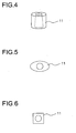
- the inner circumferential surface of the tubular protective member 11 may be formed to have a taper shape that matches the outer circumferential surface of the diffusion-plate supporting pin 10. This makes it possible for the protective member 11 to be positioned in the height direction easily.
- the area increases where the diffusion-plate supporting pin 10 is in contact with the protective member 11, and, by friction, it is possible to easily prevent the protective member 11 from coming off.
- the protective member 11 may have an elliptic or a rectangular sectional shape.
- an arrow-headed projection 10a may be formed at the tip of the diffusion-plate supporting pin 10.
- a conical projection 10a may be formed at the tip of the diffusion-plate supporting pin 10. Note that in Figs. 7 and 8 , (a) is a plan view and (b) is a side view.
- the present invention can be used in lighting apparatuses that illuminate display panels such as liquid crystal panels, and in display apparatuses such as television receivers and displays that employ such lighting apparatuses.
Landscapes
- Physics & Mathematics (AREA)
- Nonlinear Science (AREA)
- Optics & Photonics (AREA)
- Crystallography & Structural Chemistry (AREA)
- Chemical & Material Sciences (AREA)
- General Physics & Mathematics (AREA)
- Mathematical Physics (AREA)
- Liquid Crystal (AREA)
- Devices For Indicating Variable Information By Combining Individual Elements (AREA)
- Planar Illumination Modules (AREA)
- Securing Globes, Refractors, Reflectors Or The Like (AREA)
- Transforming Electric Information Into Light Information (AREA)
- Illuminated Signs And Luminous Advertising (AREA)
Abstract
Description
- The present invention relates to a lighting apparatus that illuminates a display panel such as a liquid crystal panel, and to a display apparatus and a television receiver employing such a lighting apparatus.
- A conventional display apparatus is disclosed in
Patent Document 1.Fig. 9 is a side sectional view schematically showing the display apparatus. Thedisplay apparatus 1 has alighting apparatus 3 that faces adisplay panel 2. Thelighting apparatus 3 is provided with a back chassis 4 - formed of metal -, which is open at the display panel 2-side and covers the rear side of thelighting apparatus 3. Inside theback chassis 4, a plurality oflight sources 5 comprising long-length fluorescent tubes are arranged side by side. - At the open side of the
back chassis 4, adiffusion plate 7 facing thelight sources 5 is disposed. Thediffusion plate 7 has its periphery held by theback chassis 4 and diffuses light emitted from thelight sources 5 so as to make light for illuminating thedisplay panel 2 uniform. In addition, thediffusion plate 7 is supported by diffusion-plate supporting pins 10 having a sharp point, which are fitted to theback chassis 4. - As the diffusion-plate supporting
pins 10, a plurality of them are provided between thelight sources 5 so that thediffusion plate 7 and thelight sources 5 are kept apart. This prevents thelight sources 5 reflected in display images, which is caused by thediffusion plate 7 being thermally deformed by the heat from thelight sources 5 and coming closer to thelight sources 5. - Patent Document 1:
JP-A-2005-347005 pages 4 to 9,Fig. 2 ) - According to the above-described
conventional display apparatus 1, however, thelight sources 5 may disadvantageously collide with the diffusion-plate supporting pins 10 and brake when shock acts on thedisplay apparatus 1 during transportation etc. In particular, on arranging display screens vertically, when thelight sources 5 extend horizontally and are arranged side by side in the vertical direction, thelight sources 5 are likely to collide with the diffusion-plate supporting pins 10 due to deflection caused by their own weight. - An object of the present invention is to provide a lighting apparatus in which breakage of a light source can be prevented, and to provide a display apparatus and a television receiver that employ such a lighting apparatus.
- To achieve the above object, according to the present invention, a lighting apparatus comprises: a back chassis covering the rear side of the lighting apparatus; a light source comprising a fluorescent tube held on the back chassis, the fluorescent tube having parts extending in one direction arranged side by side in a direction perpendicular to the direction of extension; a diffusion plate arranged to face the light source to diffuse light emitted from the light source; a diffusion-plate supporting pin arranged upright between adjacent parts of the light source to support the diffusion plate; and a protective member arranged around the diffusion-plate supporting pin and formed of a shock absorbing material absorbing shock by elasticity.
- With this arrangement, the back chassis covers the rear side of the lighting apparatus and holds the light source comprising a fluorescent tube. The light source comprising a plurality of fluorescent tubes or a meandering fluorescent tube that, preferably, has parts extending horizontally to be arranged side by side in the vertical direction. Between adjacent parts of the light source, the diffusion-plate supporting pin that is fitted to the back chassis is arranged, and the diffusion plate facing the light source makes contact with the diffusion-plate supporting pin to be supported thereby. By application of a voltage, light emitted from the light source is diffused by the diffusion plate and illuminates a display panel that faces the diffusion plate. The diffusion-plate supporting pin is provided with the protective member that covers around it. The protective member is formed of a shock absorbing material such as resin or rubber, and absorbs shock when the light source collides with it.
- Moreover, in the lighting apparatus arranged as described above, a projection is provided on the circumferential surface of the diffusion-plate supporting pin, and the protective member through which the diffusion-plate supporting pin is inserted has its diffusion plate-side locked by the projection. With this arrangement, the tubular protective member is put on the diffusion-plate supporting pin from its tip. Passing the projection, the protective member is arranged on the base side of the projection, and has its diffusion plate-side locked by the projection so that it does not come off.
- According to the invention, in the lighting apparatus arranged as described above, the outer circumference surface of the diffusion-plate supporting pin is formed to have a taper shape, and the inner circumference surface of the protective member through which the diffusion-plate supporting pin is inserted is formed to have a taper shape.
- Moreover, according to the invention, in the lighting apparatus arranged as described above, a concave part and a convex part are formed at the outer circumference surface of the protective member through which the diffusion-plate supporting pin is inserted.
- Moreover, according to the invention, in the lighting apparatus arranged as described above, parts of the light source extend in the horizontal direction arranged side by side in the vertical direction.
- Moreover, according to the invention, in the lighting apparatus arranged as described above, the protective member is formed to be transparent, white/whitish, or gray/grayish.
- Moreover, according to the invention, in the lighting apparatus arranged as described above, the protective member is formed of microcell polymer. With this arrangement, the protective member is formed of microcell polymer, which is a shock absorbing material such as PORON (manufactured by Rogers Inoac Corporation).
- Moreover, according to the invention, in the lighting apparatus arranged as described above, the protective member is formed of foamed polyethylene.
- Moreover, according to the invention, in the lighting apparatus arranged as described above, the protective member is formed of rubber sponge.
- Moreover, according to the invention, in the lighting apparatus arranged as described above, the protective member is formed of silicon-based gel.
- Moreover, the display apparatus according to the invention comprises the lighting apparatus arranged as described above and the display panel that faces the diffusion plate.
- Moreover, according to the invention, in the display apparatus arranged as described above, the display panel is built with a liquid crystal panel having a pair of substrates with liquid crystal sealed in between.
- Moreover, a television receiver according to the invention comprises the display apparatus arranged as described above.
- According to the present invention, the protective member arranged around the diffusion-plate supporting pin that supports the diffusion plate is formed of a shock absorbing material; thus, it is possible to prevent breakage of the light source caused by the light source colliding with the diffusion-plate supporting pin when shock acts on the lighting apparatus.
- According to the invention, the protective member through which the diffusion-plate supporting pin is inserted is locked by the projection provided on the circumference surface of the diffusion-plate supporting pin; thus, the protective member can be easily prevented from coming off.
- According to the invention, the outer circumferential surface of the diffusion-plate supporting pin and the inner circumferential surface of the protective member are formed to have a taper shape; thus, the protective member can be positioned easily in the height direction. Moreover, the area increases where the diffusion-plate supporting pin is in contact with the protective member, and, by friction, the protective member can be easily prevented from coming off.
- Moreover, according to the invention, a concave part and a convex part are formed at the outer circumferential surface of the protective member, making it easy to hold the protective member with fingers. Accordingly, it is possible to improve workability when putting the protective member on the diffusion-plate supporting pin.
- Moreover, according to the invention, even though the light source is likely to collide with the diffusion-plate supporting pin due to its own weight, since parts of the light source extend in the horizontal direction arranged side by side in the vertical direction, it is possible to surely prevent breakage of the light source caused by collision.
- Moreover, according to the invention, the protective member is formed to be transparent, white/whitish, or gray/grayish; thus, it is possible to prevent degraded image quality caused by the protective member reflected in the display panel.
- Moreover, according to the invention, the protective member is formed of microcell polymer; thus, it is possible to easily realize a protective member absorbing shock.
- Moreover, according to the invention, the protective member is formed of foamed polyethylene; thus, it is possible to easily realize a protective member absorbing shock.
- Moreover, according to the invention, the protective member is formed of rubber sponge; thus, it is possible to easily realize a protective member absorbing shock.
- Moreover, according to the invention, the protective member is formed of silicon-based gel; thus, it is possible to easily realize a protective member absorbing shock.
-
- [
Fig. 1 ] A side sectional view showing a display apparatus embodying the present invention; - [
Fig. 2 ] A plan view showing how light sources of the display apparatus embodying the invention are supported; - [
Fig. 3 ] A perspective view showing a protective member of the display apparatus embodying the invention; - [
Fig. 4 ] A perspective view showing another protective member of the display apparatus embodying the invention; - [
Fig. 5 ] A plan view showing another protective member of the display apparatus embodying the invention; - [
Fig. 6 ] A plan view showing another protective member of the display apparatus embodying the invention; - [
Fig. 7 ] A diagram showing another diffusion-plate supporting pin of the display apparatus embodying the invention; - [
Fig. 8 ] A diagram showing another diffusion-plate supporting pin of the display apparatus embodying the invention; and - [
Fig. 9 ] A side sectional view showing a conventional display apparatus. -
- 1
- display apparatus
- 2
- display panel
- 3
- lighting apparatus
- 4
- back chassis
- 5
- light source
- 6
- supporting member
- 7
- diffusion plate
- 8
- optical sheet
- 9
- connecting portion
- 10
- diffusion-plate supporting pin
- 10a
- projection
- 11
- protective member
- Hereinafter, an embodiment of the present invention will be described with reference to the accompanying drawings. For convenience of description, such parts as find their counterparts in the above-mentioned conventional example shown in
Fig. 9 are identified by common reference signs.Fig. 1 is a side sectional view showing a display apparatus according to one embodiment. Adisplay apparatus 1, such as a television receiver or a display, has alighting apparatus 3 arranged at the back of adisplay panel 2. Thedisplay panel 2 is built with a liquid crystal panel or the like that has a pair of substrates with liquid crystal sealed in between. Thedisplay panel 2 has pixels arranged in a matrix, and light emitted from thelighting apparatus 3 transmits a predetermined pixel of thedisplay panel 2 so that images are displayed. - The
lighting apparatus 3 is provided with a back chassis 4 - formed of metal -, which is open at its front and covers the rear side of thelighting apparatus 3. By forming theback chassis 4 with metal, it is possible to obtain a desired strength with a decreased thickness thereof, and thus to achieve acompact lighting apparatus 3. Inside theback chassis 4, alight source 5 is disposed. Thelight source 5 comprises a plurality of cylindrical fluorescent tubes having parts extending in one direction arranged at a predetermined interval (period) in the direction perpendicular to the direction of extension. Thelight source 5 may be arranged side by side at a predetermined interval by composing them with one or more meandering fluorescent tubes. - At the open side of the
back chassis 4, adiffusion plate 7 that faces thelight source 5 is disposed. Thediffusion plate 7 is formed of a plate-like transmissive member holding a diffusion member, and diffuses light emitted from thelight source 5. Thediffusion plate 7 has its peripheral portion held by theback chassis 4, and is supported by a diffusion-plate supporting pin 10 fitted to theback chassis 4. - The diffusion-
plate supporting pin 10 is formed out of a conical resin component having a sharp point, and is fitted to, with a claw portion (unillustrated) at its back engaged with, theback chassis 4. As the diffusion-plate supporting pin 10, a plurality of them are provided between parts of thelight source 5 having a plurality of fluorescent tubes or a meandering fluorescent tube arranged side by side, so that thediffusion plate 7 and thelight source 5 are kept apart. In this way, it is possible to prevent thelight source 5 reflected in display images, which is caused by thediffusion plate 7 being thermally deformed by the heat from thelight source 5 and coming close to thelight source 5. - Around the diffusion-
plate supporting pin 10, aprotective member 11 is arranged.Fig. 2 is a perspective view showing theprotective member 11. Theprotective member 11 is formed into a tubular shape and, as described in detail below, is formed of a shock-absorbing material absorbing shock by elasticity. - On the circumferential surface of the diffusion-
plate supporting pin 10, aprojection 10a that projects in the radius direction is provided. The tubularprotective member 11 is put on the diffusion-plate supporting pin 10 from its tip past theprojection 10a, to be arranged on the base side of theprojection 10a. In this way, theprotective member 11 is locked at its diffusion plate 7-side by theprojection 10a, so that it does not come off. - On the
diffusion plate 7, an optical sheet 8 such as a prism sheet or a lens sheet is arranged. The optical sheet 8 focuses light emitted from thediffusion plate 7 in a range of a predetermined view angle. -
Fig. 3 is a plan view showing how thelight source 5 is supported inside theback chassis 4. At opposite side portions of theback chassis 4, connectingportions 9 that hold opposite end portions of thelight source 5 to feed electric power to it are arranged. By the connectingportions 9, thelight source 5 is held in theback chassis 4. In addition, theback chassis 4 has supportingmembers 6 laid in it, and on the supportingmembers 6, thelight source 5 is placed. The supportingmembers 6 are formed of a shock-absorbing material absorbing shock by elasticity. - For the supporting
members 6 and theprotective member 11, it is possible to use resin, rubber, or the like that is spongy or has cushioning properties. Preferably, for the supportingmembers 6 and theprotective member 11, it is possible to use foamed polyethylene, rubber sponge, silicon-based gel, or the like. Further preferably, for the supportingmembers 6 and theprotective member 11, microcell polymer (for example, PORON manufactured by Rogers Inoac Corporation) is used, since it offers a high shock-absorbing performance. - The supporting
members 6 and theprotective member 11 are formed to be transparent, white/whitish, or gray/grayish. In this way, it is possible to prevent degraded image quality caused by the supportingmembers 6 and theprotective member 11 reflected in thedisplay panel 2. Note that white/whitish include not only white but also pale yellow etc.; gray/grayish include pale gray and dark gray. - The
light source 5 is connected to the connectingportions 9 with thelight source 5 pressing the supportingmembers 6 and the supportingmembers 6 being contracted. As a result, parts of thelight source 5 each has part of a circumferential surface thereof, which is smaller than half the circumference thereof, in contact with the supportingmembers 6, and thus thelight source 5 has its part between the opposite end portions supported by the supportingmembers 6. - Consequently, movement of the
light source 5 towards theback chassis 4 is prevented by the elastic behavior of the supportingmembers 6, and that towards the adjacentlight source 5 is prevented by the frictional force of the supportingmembers 6. Moreover, when shock acts on thedisplay apparatus 1, the shock force is absorbed by the supportingmembers 6. It is therefore possible to prevent deflection of thelight source 5 caused by its own weight, and to prevent breakage of thelight source 5 caused by its colliding with theback chassis 4 due to shock etc. during transportation. - Moreover, the
light source 5 is supported by the supportingmembers 6 with smaller contact area. Thus, the amount of heat dissipated from thelight source 5 via the supportingmembers 6 is reduced, and a drop in brightness in parts of the light source in contact with the supportingmembers 6 can be prevented. This makes it possible to illuminate thedisplay panel 2 with uniform brightness, and thus to achieve satisfactory display images. The supportingmembers 6 may support a plurality of parts of thelight source 5, or one place in a center part of thelight source 5. - In the
display apparatus 1 arranged as described above, light emitted from thelight source 5 enters thediffusion plate 7. The light incident on thediffusion plate 7 is diffused, and the light so diffused enters the optical sheet 8. The light incident on the optical sheet 8 has its advancing direction adjusted to be in a desired range of view angle, and irradiates thedisplay panel 2. This makes images on thedisplay panel 2 viewable. - According to the embodiment, the
protective member 11 arranged around the diffusion-plate supporting pin 10 that supports thediffusion plate 7 is formed of a shock-absorbing material; thus, it is possible to prevent breakage of thelight source 5 caused by its colliding with the diffusion-plate supporting pin 10 when shock acts on thelighting apparatus 3. - When parts of the
light source 5 are each regarded as a simple beam, the maximum amount of deflection δ (mm) of a part (of the light source 5) is expressed by formula (1). M (g) represents the mass of the part (of the light source 5), α (m/s2) represents the acceleration acting on the part (of the light source 5), 1 (mm) represents the length of the part (of the light source 5), and E (GPa) represents Young's modulus. In addition, I (m4) represents the second moment of area of the part (of the light source 5) and, suppose the part (of the light source 5) is a hollow rod with an inside diameter and an outside diameter of a (mm) and b (mm), respectively, I (m4) is then expressed by formula (2). -


- Accordingly, the
protective member 11 may be provided when the amount of deflection δ due to the acceleration α caused by shock acting on thelighting apparatus 3 is larger than the distance between parts of thelight source 5 and the diffusion-plate supporting pin 10. - When the
display apparatus 1 is arranged such that a display screen is vertical, parts of thelight source 5 extend in the horizontal direction arranged side by side in the vertical direction. Thus, when thelight source 5 deflects due to its own weight, it is likely to collide with the diffusion-plate supporting pins 10. However, thanks to the provision of theprotective member 11, breakage of thelight source 5 can be surely prevented. Note that the amount of deflection δ of thelight source 5 due to its own weight can be obtained by substituting the acceleration of gravity g (m / s2) for the acceleration α in formula (1). - In the embodiment, the
protective member 11 or the diffusion-plate supporting pin 10 may have other shapes. For example, as shown inFig. 4 , the inner circumferential surface of the tubularprotective member 11 may be formed to have a taper shape that matches the outer circumferential surface of the diffusion-plate supporting pin 10. This makes it possible for theprotective member 11 to be positioned in the height direction easily. In addition, the area increases where the diffusion-plate supporting pin 10 is in contact with theprotective member 11, and, by friction, it is possible to easily prevent theprotective member 11 from coming off. Moreover, as shown in plan views ofFigs. 5 and 6 , theprotective member 11 may have an elliptic or a rectangular sectional shape. - Moreover, as shown in
Fig. 7 , an arrow-headedprojection 10a may be formed at the tip of the diffusion-plate supporting pin 10. As shown inFig. 8 , aconical projection 10a may be formed at the tip of the diffusion-plate supporting pin 10. Note that inFigs. 7 and 8 , (a) is a plan view and (b) is a side view. - The present invention can be used in lighting apparatuses that illuminate display panels such as liquid crystal panels, and in display apparatuses such as television receivers and displays that employ such lighting apparatuses.
Claims (13)
- A lighting apparatus comprising:a back chassis covering a rear side;a light source comprising a fluorescent tube held on the back chassis, the fluorescent tube having parts extending in one direction arranged side by side in a direction perpendicular to a direction of extension;a diffusion plate arranged to face the light source to diffuse light emitted from the light source;a diffusion-plate supporting pin arranged upright between adjacent parts of the light source to support the diffusion plate; anda protective member arranged around the diffusion-plate supporting pin and formed of a shock absorbing material absorbing shock by elasticity.
- The lighting apparatus according to claim 1,
wherein a projection is provided on a circumferential surface of the diffusion-plate supporting pin, and the protective member through which the diffusion-plate supporting pin is inserted has a diffusion plate-side thereof locked by the projection. - The lighting apparatus according to claim 1,
wherein an outer circumferential surface of the diffusion-plate supporting pin is formed to have a taper shape, and an inner circumferential surface of the protective member through which the diffusion-plate supporting pin is inserted is formed to have a taper shape. - The lighting apparatus according to claim 1,
wherein a concave part and a convex part are formed at an outer circumferential surface of the protective member through which the diffusion-plate supporting pin is inserted. - The lighting apparatus according to claim 1,
wherein parts of the light source extend in a horizontal direction arranged side by side in a vertical direction. - The lighting apparatus according to claim 1,
wherein the protective member is formed to be transparent, white/whitish, or gray/grayish. - The lighting apparatus according to claim 1,
wherein the protective member is formed of microcell polymer. - The lighting apparatus according to claim 1,
wherein the protective member is formed of foamed polyethylene. - The lighting apparatus according to claim 1,
wherein the protective member is formed of rubber sponge. - The lighting apparatus according to claim 1,
wherein the protective member is formed of silicon-based gel. - A display apparatus comprising:the lighting apparatus according to claim 1; anda display panel facing the diffusion plate.
- The display apparatus according to claim 11,
wherein the display panel is built with a liquid crystal panel having a pair of substrates with liquid crystal sealed in between. - A television receiver comprising the display apparatus according to claim 11.
Applications Claiming Priority (2)
| Application Number | Priority Date | Filing Date | Title |
|---|---|---|---|
| JP2007145382 | 2007-05-31 | ||
| PCT/JP2008/050752 WO2008146499A1 (en) | 2007-05-31 | 2008-01-22 | Lighting apparatus, display apparatus and tv receiver |
Publications (3)
| Publication Number | Publication Date |
|---|---|
| EP2149741A1 true EP2149741A1 (en) | 2010-02-03 |
| EP2149741A4 EP2149741A4 (en) | 2010-11-24 |
| EP2149741B1 EP2149741B1 (en) | 2012-09-12 |
Family
ID=40074773
Family Applications (1)
| Application Number | Title | Priority Date | Filing Date |
|---|---|---|---|
| EP08710560A Not-in-force EP2149741B1 (en) | 2007-05-31 | 2008-01-22 | Lighting apparatus, display apparatus and tv receiver |
Country Status (5)
| Country | Link |
|---|---|
| US (1) | US20100157578A1 (en) |
| EP (1) | EP2149741B1 (en) |
| JP (1) | JP4954282B2 (en) |
| CN (1) | CN101680612B (en) |
| WO (1) | WO2008146499A1 (en) |
Cited By (1)
| Publication number | Priority date | Publication date | Assignee | Title |
|---|---|---|---|---|
| EP4365672A4 (en) * | 2022-01-28 | 2024-11-13 | Samsung Electronics Co., Ltd. | DISPLAY DEVICE AND ASSOCIATED LIGHT SOURCE DEVICE |
Families Citing this family (1)
| Publication number | Priority date | Publication date | Assignee | Title |
|---|---|---|---|---|
| JP2014013690A (en) * | 2012-07-04 | 2014-01-23 | Sony Corp | Display device |
Family Cites Families (16)
| Publication number | Priority date | Publication date | Assignee | Title |
|---|---|---|---|---|
| KR100640987B1 (en) * | 2000-10-14 | 2006-11-02 | 엘지.필립스 엘시디 주식회사 | Direct type backlight assembly of liquid crystal display |
| JP2004186080A (en) * | 2002-12-05 | 2004-07-02 | Tama Electric Co Ltd | Backlight device |
| TW592324U (en) * | 2002-12-19 | 2004-06-11 | Coretronic Corp | Back light apparatus |
| US6974221B2 (en) * | 2003-12-30 | 2005-12-13 | Au Optronics Corporation | Support for backlight module |
| TW200523628A (en) * | 2004-01-06 | 2005-07-16 | Hannstar Display Corp | Upright backlight module |
| TWI259311B (en) * | 2004-05-21 | 2006-08-01 | Au Optronics Corp | Supporting cone of bottom-lighting backlight module |
| JP4421947B2 (en) | 2004-06-01 | 2010-02-24 | Nec液晶テクノロジー株式会社 | Light emitting device and liquid crystal display device |
| CN2762500Y (en) * | 2004-12-23 | 2006-03-01 | 三匠国际股份有限公司 | Combined support for lamp tube and panel |
| TWI255896B (en) * | 2005-01-19 | 2006-06-01 | Au Optronics Corp | Backlight module |
| CN100359383C (en) * | 2005-06-21 | 2008-01-02 | 友达光电股份有限公司 | Backlight module of liquid crystal display and supporting structure thereof |
| CN100378544C (en) * | 2005-06-22 | 2008-04-02 | 友达光电股份有限公司 | Backlight module and lamp tube support frame thereof |
| KR20070001362A (en) * | 2005-06-29 | 2007-01-04 | 삼성전자주식회사 | LCD Display |
| JP4896669B2 (en) * | 2005-11-02 | 2012-03-14 | 三星電子株式会社 | Backlight assembly, liquid crystal display device having the same, and method of manufacturing lamp fixing member |
| JP2007157450A (en) * | 2005-12-02 | 2007-06-21 | Sharp Corp | Diffusion plate support member, backlight device, and display device |
| TWI330741B (en) * | 2006-11-02 | 2010-09-21 | Au Optronics Corp | Supporting structure and backlight module using the same |
| US7510318B2 (en) * | 2007-03-12 | 2009-03-31 | Hannstar Display Corp. | Fastening apparatus for a backlight assembly |
-
2008
- 2008-01-22 US US12/600,518 patent/US20100157578A1/en not_active Abandoned
- 2008-01-22 CN CN2008800167074A patent/CN101680612B/en not_active Expired - Fee Related
- 2008-01-22 EP EP08710560A patent/EP2149741B1/en not_active Not-in-force
- 2008-01-22 WO PCT/JP2008/050752 patent/WO2008146499A1/en not_active Ceased
- 2008-01-22 JP JP2009516191A patent/JP4954282B2/en not_active Expired - Fee Related
Cited By (1)
| Publication number | Priority date | Publication date | Assignee | Title |
|---|---|---|---|---|
| EP4365672A4 (en) * | 2022-01-28 | 2024-11-13 | Samsung Electronics Co., Ltd. | DISPLAY DEVICE AND ASSOCIATED LIGHT SOURCE DEVICE |
Also Published As
| Publication number | Publication date |
|---|---|
| US20100157578A1 (en) | 2010-06-24 |
| EP2149741A4 (en) | 2010-11-24 |
| CN101680612A (en) | 2010-03-24 |
| JPWO2008146499A1 (en) | 2010-08-19 |
| WO2008146499A1 (en) | 2008-12-04 |
| CN101680612B (en) | 2012-03-14 |
| EP2149741B1 (en) | 2012-09-12 |
| JP4954282B2 (en) | 2012-06-13 |
Similar Documents
| Publication | Publication Date | Title |
|---|---|---|
| US6974221B2 (en) | Support for backlight module | |
| RU2483240C2 (en) | Illumination device and display device | |
| US20020044437A1 (en) | Back light assembly for liquid crystal display device | |
| US20050099604A1 (en) | Backlight device and liquid crystal display device therewith | |
| KR100982444B1 (en) | LCD Display | |
| US20090310367A1 (en) | Composite light guide structure | |
| JP3936895B2 (en) | Backlight device and liquid crystal display device | |
| EP2149741B1 (en) | Lighting apparatus, display apparatus and tv receiver | |
| US9030748B2 (en) | Brightness enhancement film, backlight assembly, and display apparatus | |
| JP2009272199A (en) | Shock absorbing type spacer pin in backlight for liquid crystal panel | |
| US6960002B2 (en) | Direct backlight module | |
| JP6212215B2 (en) | Display device | |
| US20100165602A1 (en) | Lighting apparatus, display apparatus, and tv receiver | |
| US7612841B2 (en) | Mold frame and liquid crystal display having the same | |
| US8348444B2 (en) | Backlight module | |
| EP1435532B1 (en) | Back light apparatus | |
| KR970008276A (en) | A color selection device of a color display device and a cathode ray tube | |
| CN101109868A (en) | Direct Type Backlight Assembly | |
| US20070008450A1 (en) | Display device | |
| KR100589780B1 (en) | Support for LCD Panel | |
| US20060092660A1 (en) | Backlight device and liquid crystal display apparatus of using the same | |
| KR101250782B1 (en) | Backlight assembly | |
| JP4351145B2 (en) | LIGHTING DEVICE AND LIQUID CRYSTAL DISPLAY DEVICE USING THE SAME | |
| CN101377588A (en) | Backlight module and diffusing plate thereof, and planar display using the same | |
| JP2010192319A (en) | Lighting apparatus, and display device |
Legal Events
| Date | Code | Title | Description |
|---|---|---|---|
| PUAI | Public reference made under article 153(3) epc to a published international application that has entered the european phase |
Free format text: ORIGINAL CODE: 0009012 |
|
| 17P | Request for examination filed |
Effective date: 20091029 |
|
| AK | Designated contracting states |
Kind code of ref document: A1 Designated state(s): AT BE BG CH CY CZ DE DK EE ES FI FR GB GR HR HU IE IS IT LI LT LU LV MC MT NL NO PL PT RO SE SI SK TR |
|
| AX | Request for extension of the european patent |
Extension state: AL BA MK RS |
|
| DAX | Request for extension of the european patent (deleted) | ||
| A4 | Supplementary search report drawn up and despatched |
Effective date: 20101025 |
|
| GRAP | Despatch of communication of intention to grant a patent |
Free format text: ORIGINAL CODE: EPIDOSNIGR1 |
|
| RIN1 | Information on inventor provided before grant (corrected) |
Inventor name: KUROMIZU, YASUMORI |
|
| GRAS | Grant fee paid |
Free format text: ORIGINAL CODE: EPIDOSNIGR3 |
|
| GRAA | (expected) grant |
Free format text: ORIGINAL CODE: 0009210 |
|
| AK | Designated contracting states |
Kind code of ref document: B1 Designated state(s): AT BE BG CH CY CZ DE DK EE ES FI FR GB GR HR HU IE IS IT LI LT LU LV MC MT NL NO PL PT RO SE SI SK TR |
|
| REG | Reference to a national code |
Ref country code: GB Ref legal event code: FG4D |
|
| REG | Reference to a national code |
Ref country code: CH Ref legal event code: EP |
|
| REG | Reference to a national code |
Ref country code: AT Ref legal event code: REF Ref document number: 575277 Country of ref document: AT Kind code of ref document: T Effective date: 20120915 |
|
| REG | Reference to a national code |
Ref country code: IE Ref legal event code: FG4D |
|
| REG | Reference to a national code |
Ref country code: NL Ref legal event code: T3 |
|
| REG | Reference to a national code |
Ref country code: DE Ref legal event code: R096 Ref document number: 602008018712 Country of ref document: DE Effective date: 20121108 |
|
| PG25 | Lapsed in a contracting state [announced via postgrant information from national office to epo] |
Ref country code: FI Free format text: LAPSE BECAUSE OF FAILURE TO SUBMIT A TRANSLATION OF THE DESCRIPTION OR TO PAY THE FEE WITHIN THE PRESCRIBED TIME-LIMIT Effective date: 20120912 Ref country code: CY Free format text: LAPSE BECAUSE OF FAILURE TO SUBMIT A TRANSLATION OF THE DESCRIPTION OR TO PAY THE FEE WITHIN THE PRESCRIBED TIME-LIMIT Effective date: 20120912 Ref country code: LT Free format text: LAPSE BECAUSE OF FAILURE TO SUBMIT A TRANSLATION OF THE DESCRIPTION OR TO PAY THE FEE WITHIN THE PRESCRIBED TIME-LIMIT Effective date: 20120912 Ref country code: NO Free format text: LAPSE BECAUSE OF FAILURE TO SUBMIT A TRANSLATION OF THE DESCRIPTION OR TO PAY THE FEE WITHIN THE PRESCRIBED TIME-LIMIT Effective date: 20121212 Ref country code: HR Free format text: LAPSE BECAUSE OF FAILURE TO SUBMIT A TRANSLATION OF THE DESCRIPTION OR TO PAY THE FEE WITHIN THE PRESCRIBED TIME-LIMIT Effective date: 20120912 |
|
| REG | Reference to a national code |
Ref country code: AT Ref legal event code: MK05 Ref document number: 575277 Country of ref document: AT Kind code of ref document: T Effective date: 20120912 |
|
| REG | Reference to a national code |
Ref country code: LT Ref legal event code: MG4D Effective date: 20120912 |
|
| PG25 | Lapsed in a contracting state [announced via postgrant information from national office to epo] |
Ref country code: SE Free format text: LAPSE BECAUSE OF FAILURE TO SUBMIT A TRANSLATION OF THE DESCRIPTION OR TO PAY THE FEE WITHIN THE PRESCRIBED TIME-LIMIT Effective date: 20120912 Ref country code: SI Free format text: LAPSE BECAUSE OF FAILURE TO SUBMIT A TRANSLATION OF THE DESCRIPTION OR TO PAY THE FEE WITHIN THE PRESCRIBED TIME-LIMIT Effective date: 20120912 Ref country code: GR Free format text: LAPSE BECAUSE OF FAILURE TO SUBMIT A TRANSLATION OF THE DESCRIPTION OR TO PAY THE FEE WITHIN THE PRESCRIBED TIME-LIMIT Effective date: 20121213 Ref country code: LV Free format text: LAPSE BECAUSE OF FAILURE TO SUBMIT A TRANSLATION OF THE DESCRIPTION OR TO PAY THE FEE WITHIN THE PRESCRIBED TIME-LIMIT Effective date: 20120912 |
|
| PG25 | Lapsed in a contracting state [announced via postgrant information from national office to epo] |
Ref country code: BE Free format text: LAPSE BECAUSE OF FAILURE TO SUBMIT A TRANSLATION OF THE DESCRIPTION OR TO PAY THE FEE WITHIN THE PRESCRIBED TIME-LIMIT Effective date: 20120912 Ref country code: RO Free format text: LAPSE BECAUSE OF FAILURE TO SUBMIT A TRANSLATION OF THE DESCRIPTION OR TO PAY THE FEE WITHIN THE PRESCRIBED TIME-LIMIT Effective date: 20120912 Ref country code: IS Free format text: LAPSE BECAUSE OF FAILURE TO SUBMIT A TRANSLATION OF THE DESCRIPTION OR TO PAY THE FEE WITHIN THE PRESCRIBED TIME-LIMIT Effective date: 20130112 Ref country code: EE Free format text: LAPSE BECAUSE OF FAILURE TO SUBMIT A TRANSLATION OF THE DESCRIPTION OR TO PAY THE FEE WITHIN THE PRESCRIBED TIME-LIMIT Effective date: 20120912 Ref country code: ES Free format text: LAPSE BECAUSE OF FAILURE TO SUBMIT A TRANSLATION OF THE DESCRIPTION OR TO PAY THE FEE WITHIN THE PRESCRIBED TIME-LIMIT Effective date: 20121223 Ref country code: CZ Free format text: LAPSE BECAUSE OF FAILURE TO SUBMIT A TRANSLATION OF THE DESCRIPTION OR TO PAY THE FEE WITHIN THE PRESCRIBED TIME-LIMIT Effective date: 20120912 |
|
| PGFP | Annual fee paid to national office [announced via postgrant information from national office to epo] |
Ref country code: DE Payment date: 20130129 Year of fee payment: 6 |
|
| PG25 | Lapsed in a contracting state [announced via postgrant information from national office to epo] |
Ref country code: PT Free format text: LAPSE BECAUSE OF FAILURE TO SUBMIT A TRANSLATION OF THE DESCRIPTION OR TO PAY THE FEE WITHIN THE PRESCRIBED TIME-LIMIT Effective date: 20130114 Ref country code: SK Free format text: LAPSE BECAUSE OF FAILURE TO SUBMIT A TRANSLATION OF THE DESCRIPTION OR TO PAY THE FEE WITHIN THE PRESCRIBED TIME-LIMIT Effective date: 20120912 Ref country code: PL Free format text: LAPSE BECAUSE OF FAILURE TO SUBMIT A TRANSLATION OF THE DESCRIPTION OR TO PAY THE FEE WITHIN THE PRESCRIBED TIME-LIMIT Effective date: 20120912 |
|
| PGFP | Annual fee paid to national office [announced via postgrant information from national office to epo] |
Ref country code: NL Payment date: 20130121 Year of fee payment: 6 |
|
| PG25 | Lapsed in a contracting state [announced via postgrant information from national office to epo] |
Ref country code: AT Free format text: LAPSE BECAUSE OF FAILURE TO SUBMIT A TRANSLATION OF THE DESCRIPTION OR TO PAY THE FEE WITHIN THE PRESCRIBED TIME-LIMIT Effective date: 20120912 |
|
| PLBE | No opposition filed within time limit |
Free format text: ORIGINAL CODE: 0009261 |
|
| STAA | Information on the status of an ep patent application or granted ep patent |
Free format text: STATUS: NO OPPOSITION FILED WITHIN TIME LIMIT |
|
| PG25 | Lapsed in a contracting state [announced via postgrant information from national office to epo] |
Ref country code: BG Free format text: LAPSE BECAUSE OF FAILURE TO SUBMIT A TRANSLATION OF THE DESCRIPTION OR TO PAY THE FEE WITHIN THE PRESCRIBED TIME-LIMIT Effective date: 20121212 Ref country code: DK Free format text: LAPSE BECAUSE OF FAILURE TO SUBMIT A TRANSLATION OF THE DESCRIPTION OR TO PAY THE FEE WITHIN THE PRESCRIBED TIME-LIMIT Effective date: 20120912 |
|
| 26N | No opposition filed |
Effective date: 20130613 |
|
| PG25 | Lapsed in a contracting state [announced via postgrant information from national office to epo] |
Ref country code: MC Free format text: LAPSE BECAUSE OF NON-PAYMENT OF DUE FEES Effective date: 20130131 Ref country code: IT Free format text: LAPSE BECAUSE OF FAILURE TO SUBMIT A TRANSLATION OF THE DESCRIPTION OR TO PAY THE FEE WITHIN THE PRESCRIBED TIME-LIMIT Effective date: 20120912 |
|
| REG | Reference to a national code |
Ref country code: CH Ref legal event code: PL |
|
| GBPC | Gb: european patent ceased through non-payment of renewal fee |
Effective date: 20130122 |
|
| REG | Reference to a national code |
Ref country code: DE Ref legal event code: R097 Ref document number: 602008018712 Country of ref document: DE Effective date: 20130613 |
|
| REG | Reference to a national code |
Ref country code: IE Ref legal event code: MM4A |
|
| REG | Reference to a national code |
Ref country code: FR Ref legal event code: ST Effective date: 20130930 |
|
| PG25 | Lapsed in a contracting state [announced via postgrant information from national office to epo] |
Ref country code: CH Free format text: LAPSE BECAUSE OF NON-PAYMENT OF DUE FEES Effective date: 20130131 Ref country code: LI Free format text: LAPSE BECAUSE OF NON-PAYMENT OF DUE FEES Effective date: 20130131 |
|
| PG25 | Lapsed in a contracting state [announced via postgrant information from national office to epo] |
Ref country code: FR Free format text: LAPSE BECAUSE OF NON-PAYMENT OF DUE FEES Effective date: 20130131 Ref country code: GB Free format text: LAPSE BECAUSE OF NON-PAYMENT OF DUE FEES Effective date: 20130122 |
|
| PG25 | Lapsed in a contracting state [announced via postgrant information from national office to epo] |
Ref country code: IE Free format text: LAPSE BECAUSE OF NON-PAYMENT OF DUE FEES Effective date: 20130122 |
|
| PG25 | Lapsed in a contracting state [announced via postgrant information from national office to epo] |
Ref country code: MT Free format text: LAPSE BECAUSE OF FAILURE TO SUBMIT A TRANSLATION OF THE DESCRIPTION OR TO PAY THE FEE WITHIN THE PRESCRIBED TIME-LIMIT Effective date: 20120912 |
|
| REG | Reference to a national code |
Ref country code: DE Ref legal event code: R119 Ref document number: 602008018712 Country of ref document: DE |
|
| REG | Reference to a national code |
Ref country code: NL Ref legal event code: V1 Effective date: 20140801 |
|
| REG | Reference to a national code |
Ref country code: DE Ref legal event code: R119 Ref document number: 602008018712 Country of ref document: DE Effective date: 20140801 |
|
| PG25 | Lapsed in a contracting state [announced via postgrant information from national office to epo] |
Ref country code: DE Free format text: LAPSE BECAUSE OF NON-PAYMENT OF DUE FEES Effective date: 20140801 Ref country code: NL Free format text: LAPSE BECAUSE OF NON-PAYMENT OF DUE FEES Effective date: 20140801 |
|
| PG25 | Lapsed in a contracting state [announced via postgrant information from national office to epo] |
Ref country code: TR Free format text: LAPSE BECAUSE OF FAILURE TO SUBMIT A TRANSLATION OF THE DESCRIPTION OR TO PAY THE FEE WITHIN THE PRESCRIBED TIME-LIMIT Effective date: 20120912 |
|
| PG25 | Lapsed in a contracting state [announced via postgrant information from national office to epo] |
Ref country code: HU Free format text: LAPSE BECAUSE OF FAILURE TO SUBMIT A TRANSLATION OF THE DESCRIPTION OR TO PAY THE FEE WITHIN THE PRESCRIBED TIME-LIMIT; INVALID AB INITIO Effective date: 20080122 Ref country code: LU Free format text: LAPSE BECAUSE OF NON-PAYMENT OF DUE FEES Effective date: 20130122 |