EP2149740A1 - Backlight unit, display unit and television receiver - Google Patents
Backlight unit, display unit and television receiver Download PDFInfo
- Publication number
- EP2149740A1 EP2149740A1 EP08710558A EP08710558A EP2149740A1 EP 2149740 A1 EP2149740 A1 EP 2149740A1 EP 08710558 A EP08710558 A EP 08710558A EP 08710558 A EP08710558 A EP 08710558A EP 2149740 A1 EP2149740 A1 EP 2149740A1
- Authority
- EP
- European Patent Office
- Prior art keywords
- diffusion
- plate
- diffusion plate
- backlight unit
- presser member
- Prior art date
- Legal status (The legal status is an assumption and is not a legal conclusion. Google has not performed a legal analysis and makes no representation as to the accuracy of the status listed.)
- Withdrawn
Links
Images



Classifications
-
- G—PHYSICS
- G02—OPTICS
- G02F—OPTICAL DEVICES OR ARRANGEMENTS FOR THE CONTROL OF LIGHT BY MODIFICATION OF THE OPTICAL PROPERTIES OF THE MEDIA OF THE ELEMENTS INVOLVED THEREIN; NON-LINEAR OPTICS; FREQUENCY-CHANGING OF LIGHT; OPTICAL LOGIC ELEMENTS; OPTICAL ANALOGUE/DIGITAL CONVERTERS
- G02F1/00—Devices or arrangements for the control of the intensity, colour, phase, polarisation or direction of light arriving from an independent light source, e.g. switching, gating or modulating; Non-linear optics
- G02F1/01—Devices or arrangements for the control of the intensity, colour, phase, polarisation or direction of light arriving from an independent light source, e.g. switching, gating or modulating; Non-linear optics for the control of the intensity, phase, polarisation or colour
- G02F1/13—Devices or arrangements for the control of the intensity, colour, phase, polarisation or direction of light arriving from an independent light source, e.g. switching, gating or modulating; Non-linear optics for the control of the intensity, phase, polarisation or colour based on liquid crystals, e.g. single liquid crystal display cells
- G02F1/133—Constructional arrangements; Operation of liquid crystal cells; Circuit arrangements
- G02F1/1333—Constructional arrangements; Manufacturing methods
- G02F1/1335—Structural association of cells with optical devices, e.g. polarisers or reflectors
- G02F1/1336—Illuminating devices
- G02F1/133602—Direct backlight
- G02F1/133606—Direct backlight including a specially adapted diffusing, scattering or light controlling members
-
- G—PHYSICS
- G02—OPTICS
- G02F—OPTICAL DEVICES OR ARRANGEMENTS FOR THE CONTROL OF LIGHT BY MODIFICATION OF THE OPTICAL PROPERTIES OF THE MEDIA OF THE ELEMENTS INVOLVED THEREIN; NON-LINEAR OPTICS; FREQUENCY-CHANGING OF LIGHT; OPTICAL LOGIC ELEMENTS; OPTICAL ANALOGUE/DIGITAL CONVERTERS
- G02F1/00—Devices or arrangements for the control of the intensity, colour, phase, polarisation or direction of light arriving from an independent light source, e.g. switching, gating or modulating; Non-linear optics
- G02F1/01—Devices or arrangements for the control of the intensity, colour, phase, polarisation or direction of light arriving from an independent light source, e.g. switching, gating or modulating; Non-linear optics for the control of the intensity, phase, polarisation or colour
- G02F1/13—Devices or arrangements for the control of the intensity, colour, phase, polarisation or direction of light arriving from an independent light source, e.g. switching, gating or modulating; Non-linear optics for the control of the intensity, phase, polarisation or colour based on liquid crystals, e.g. single liquid crystal display cells
- G02F1/133—Constructional arrangements; Operation of liquid crystal cells; Circuit arrangements
- G02F1/1333—Constructional arrangements; Manufacturing methods
- G02F1/133308—Support structures for LCD panels, e.g. frames or bezels
- G02F1/133317—Intermediate frames, e.g. between backlight housing and front frame
-
- G—PHYSICS
- G02—OPTICS
- G02F—OPTICAL DEVICES OR ARRANGEMENTS FOR THE CONTROL OF LIGHT BY MODIFICATION OF THE OPTICAL PROPERTIES OF THE MEDIA OF THE ELEMENTS INVOLVED THEREIN; NON-LINEAR OPTICS; FREQUENCY-CHANGING OF LIGHT; OPTICAL LOGIC ELEMENTS; OPTICAL ANALOGUE/DIGITAL CONVERTERS
- G02F2201/00—Constructional arrangements not provided for in groups G02F1/00 - G02F7/00
- G02F2201/54—Arrangements for reducing warping-twist
Definitions
- the present invention relates to a backlight unit, a display unit, and a television receiver, and in particular the invention relates to a backlight unit, a display unit, and a television receiver, all of which are provided with a diffusion plate that diffuses light emitted from a light source.
- Patent Document 1 there are known backlight units provided with a diffusion plate that diffuses light emitted from a light source (e.g., see Patent Document 1).
- a backlight unit is disclosed that is provided with fluorescent tubes (light sources), a diffusion plate diffusing light emitted from the fluorescent tubes and having holes (catching parts) in a peripheral portion thereof, and with pulling means engaging with the holes in the diffusion plate and applying tension to the diffusion plate in the planar direction.
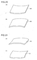
- a diffusion plate 100 warps like a barrel (see Fig. 20 (a) and (b) ) or a saddle (see Fig. 21 (a) and (b) ), and in addition the peripheral portion moves inward in the planar direction.
- the present invention is devised to solve the above problems, and an object of the invention is to provide a backlight unit, a display unit, and a television receiver, all in which warping in a diffusion plate can be sufficiently prevented.
- a backlight unit comprises: a light source; a diffusion plate diffusing light emitted from the light source and having a catching part in a peripheral portion thereof; a support pedestal supporting the diffusion plate; an optical sheet arranged on the diffusion plate; and a diffusion-plate presser member engaging with the catching part of the diffusion plate and sandwiching the diffusion plate between the support pedestal.
- the diffusion plate having the catching part in the peripheral portion, and the diffusion-plate presser member engaging with the catching part of the diffusion plate. This makes it possible, by the diffusion-plate presser member, to prevent the peripheral portion of the diffusion plate from moving inward in the planar direction. Thus, it is possible to prevent warping in the diffusion plate caused by a rise in temperature when the light source is lit. Furthermore, there are provided the support pedestal that supports the diffusion plate, and the diffusion-plate presser member that sandwiches the diffusion plate between the support pedestal. This makes it possible to fix (support) the diffusion plate in the direction perpendicular to the planar direction of the diffusion plate.
- the diffusion-plate presser member that engages with the catching part of the diffusion plate and sandwiches the diffusion plate between the support pedestal. This makes it possible, by the diffusion-plate presser member, to prevent the peripheral portion of the diffusion plate moving inward in the planar direction, and in addition to prevent the diffusion plate from deforming in the direction perpendicular to the planar direction of the diffusion plate. Thus, it is possible to prevent increased number of components, compared with a case in which separate members are provided for preventing the peripheral portion of the diffusion plate from moving inward in the planar direction, and for preventing the diffusion plate from deforming in the direction perpendicular to the planar direction of the diffusion plate.
- the catching part of the diffusion plate is formed so as to extend along the peripheral portion of the diffusion plate.
- the diffusion-plate presser member is engaged with the catching part of the diffusion plate with tension applied in the planar direction of the diffusion plate.
- a part of the diffusion-plate presser member that engages with the catching part of the diffusion plate is formed to be elastically deformable.
- the diffusion-plate presser member sandwiches the diffusion plate between the support pedestal by pressing the diffusion plate, and the diffusion-plate presser member has biasing means that biases the diffusion plate in the direction in which the diffusion plate is pressed.
- a part of the diffusion-plate presser member that makes contact with the diffusion plate is formed of resin.
- the part of the diffusion-plate presser member that makes contact with the diffusion plate is formed of resin; thereby, it is possible to easily form the part of the diffusion-plate presser member that engages with the catching part of the diffusion plate elastically deformable.
- the diffusion-plate presser member is formed of metal or a metal compound.
- a high solidity can be achieved in the diffusion-plate presser member, and thus it is possible to prevent the diffusion-plate presser member from deforming.
- the color of the surface of the diffusion-plate presser member is made white/whitish or black/blackish.
- a display unit comprises the backlight unit described above, and a display panel illuminated by the backlight unit.
- the display panel has a liquid crystal display panel in which liquid crystal is sealed in between a pair of substrates.
- a television receiver comprises the display unit described above, a cabinet housing the display unit, a tuner, and a speaker. With this structure, it is possible to obtain a television receiver in which warping in a diffusion plate can be sufficiently prevented.
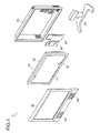
- Fig. 1 is an exploded perspective view showing the overall structure of a liquid crystal television receiver provided with a backlight unit according to a first embodiment of the present invention.
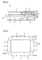
- Fig. 2 is a sectional view showing the structure of a liquid crystal display unit having the backlight unit according to the first embodiment of the invention.
- Fig. 3 is a plan view showing the structure of the backlight unit shown in Fig. 2 around a diffusion plate.
- Fig. 4 is a plan view showing the structure of the diffusion plate of the backlight unit shown in Fig. 2 .
- Fig. 5 is a sectional view showing the structure of a diffusion-plate presser member of the backlight unit shown in Fig. 2 .
- a description will be given of the structure of the liquid crystal television receiver 1 provided with the backlight unit 20 according to the first embodiment of the present invention.
- the liquid crystal television receiver 1 is one example of a "television receiver" according to the invention.
- the speakers 40, the tuner 50, the power supply 60, and the supporter 70 those that have been conventionally used commonly can be applied; thus, they will be described briefly.
- the liquid crystal display unit 10 is one example of a "display unit” according to the invention
- the front cabinet 30 and the rear cabinet 31 are examples of a "cabinet" according to the invention.
- the front cabinet 30 and the rear cabinet 31 house the liquid crystal display unit 10, the tuner 50, and the power supply 60, and are supported by the supporter 70.
- the tuner 50 has a function for generating an image signal and an audio signal of a predetermined channel from a radio wave received.
- the speaker 40 has a function for outputting sound based on the audio signal generated by the tuner 50.
- the power supply 60 is so designed as to feed electric power to the liquid crystal display unit 10, the speakers 40, and the tuner 50. Note that the speakers 40, the tuner 50, and the power supply 60 may be built into the liquid crystal display unit 10.
- the liquid crystal display unit 10 comprises: the backlight unit 20; a liquid crystal display panel 11 arranged at the front of the backlight unit 20; and a front chassis 12 and a frame 13 that sandwich the liquid crystal display panel 11 to support it.
- the liquid crystal display panel 11 is one example of a "display panel" according to the invention.
- the liquid crystal display panel 11 has pixels arrayed in a matrix.
- the liquid crystal display panel 11 has a function for displaying images by being illuminated by the backlight unit 20 and having the light from the backlight unit 20 passing through it.
- the liquid crystal display panel 11 is formed with liquid crystal being sealed in between a pair of substrates.
- the backlight unit 20 comprises: a plurality of light sources 21; a diffusion plate 22 that diffuses light emitted from the light sources 21; an optical sheet 23 arranged on the front surface of the diffusion plate 22; a back chassis 24 that covers the light sources 21 and the diffusion plate 22 from behind; a support pedestal 25 that supports the diffusion plate 22; and a diffusion-plate presser member 26 that sandwiches the diffusion plate 22 between the support pedestal 25.
- the light sources 21 are formed of a plurality of cylindrical fluorescent tubes arranged at a predetermined interval (period), and are fixed at the front of the back chassis 24. Note that the light sources 21 may be formed of a meandering fluorescent tube.
- the diffusion plate 22 is formed of a plate-like transmissive member holding a diffusion member. In addition, the diffusion plate 22 is arranged so as to face the liquid crystal display panel 11.
- the diffusion plate 22 has a rectangular shape as seen in a plan view, and catching parts 22a - having a concave shape - are formed at the four sides, forming a peripheral portion, of the rectangular shape, one at each of the four sides.
- the catching parts 22a are formed on the front surface (upper surface) of the diffusion plate 22.
- the catching parts 22a are formed such that two opposing catching parts 22a are arranged in parallel.
- the catching parts 22a have a narrow rectangular shape so as to extend along the peripheral portion of the diffusion plate 22.
- the catching parts 22a may be formed to have a shape other than rectangular; for example, they may be formed such that those at two opposing sides have an arc shape or the like, or may be formed to have a narrow elliptic shape. Moreover, the catching parts 22a may be formed to have other shapes.
- each of the catching parts 22a is formed such that both ends of the catching part 22a do not reach the ends (of the four sides) of the diffusion plate 22.
- the catching part 22a is formed such that it has a depth smaller than the thickness of the diffusion plate 22. That is, the catching part 22a is formed such that it does not penetrate through the diffusion plate 22.
- the optical sheet 23 is formed of a prism sheet or a lens sheet, and has a function for focusing light from the diffusion plate 22 in a predetermined viewing angle. As shown in Fig. 3 , the optical sheet 23 has an area smaller than the diffusion plate 22, and is arranged inward than the diffusion-plate presser member 26. In addition, the optical sheet 23 is held on the front surface (upper surface) of the diffusion plate 22 by an unillustrated optical-sheet presser member. Note that a gap may be provided between the optical sheet 23 and the unillustrated optical-sheet presser member so that no pressing force acts on the optical sheet 23.
- the support pedestal 25 is fixed at the peripheral portion of the back chassis 24, the support pedestal 25 is fixed. Note that the support pedestal 25 may be formed integral with the back chassis 24.
- the diffusion-plate presser member 26 is formed of a plate member 26a - formed of metal - to which a plurality of screws 27 are fitted, and a catching member 26b formed of resin, rubber, or the like that can be elastically deformed.
- the plate member 26a may be formed integral with the catching member 26b using resin, rubber, or the like, in which case highly solid resin, rubber, or the like is preferably used.
- the diffusion-plate presser member 26 may be formed of metal or a metal compound. In this case, it is possible to enhance the solidity of the diffusion-plate presser member 26, and thus possible to prevent deformation of the diffusion-plate presser member 26.
- the plate member 26a of the diffusion-plate presser member 26 has a surface of which the color is white/whitish or black/blackish.
- the diffusion-plate presser member 26 sandwiches the diffusion plate 22 between the support surface 25a (see Fig. 2 ) of the support pedestal 25, by the plate member 26a being fixed with the plurality of screws 27 screwed to the threaded holes 25b (see Fig. 2 ) of the support pedestal 25.
- the diffusion-plate presser member 26 be formed such that the catching member 26b presses the catching part 22a of the diffusion plate 22 toward the support pedestal 25.
- the diffusion-plate presser member 26 may be formed such that the back surface (lower surface) of the plate member 26a presses the diffusion plate 22 toward the support pedestal 25.
- the catching member 26b of the diffusion-plate presser member 26 is engaged with the catching part 22a of the diffusion plate 22 with tension applied in the planar direction (the direction indicated by an arrow A) of the diffusion plate 22.
- the diffusion-plate presser member 26 is fixed with the outside surface of the catching member 26b of the diffusion-plate presser member 26 making contact with the inside surface of the catching part 22a of the diffusion plate 22, and the diffusion plate 22 is fixed with the peripheral portion being pulled outward.
- the diffusion plate 22 that has the catching part 22a at the peripheral portion, and the diffusion-plate presser member 26 that engages with the catching part 22a of the diffusion plate 22.
- the support pedestal 25 that supports the diffusion plate 22, and the diffusion-plate presser member 26 that sandwiches the diffusion plate 22 between the support pedestal 25. This makes it possible to fix (support) the diffusion plate 22 in the direction perpendicular to the planar direction of the diffusion plate 22.
- the diffusion plate 22 it is possible to prevent the diffusion plate 22 from deforming in the direction perpendicular to the planar direction of the diffusion plate 22.
- warping in the diffusion plate 22 can be sufficiently prevented.
- the diffusion-plate presser member 26 that engages with the catching part 22a of the diffusion plate 22 and sandwiches the diffusion plate 22 between the support pedestal 25.
- the catching part 22a of the diffusion plate 22 is formed so as to extend along the peripheral portion of the diffusion plate 22. This makes it possible, by the diffusion-plate presser member 26, to evenly prevent the peripheral portion of the diffusion plate 22 from moving toward the inner side in the planar direction, and to evenly prevent the diffusion plate 22 from deforming in the direction perpendicular to the planar direction of the diffusion plate 22. Thus, warping in the diffusion plate 22 can be prevented effectively.
- the catching member 26b of the diffusion-plate presser member 26 is engaged with the catching part 22a of the diffusion plate 22 with tension applied in the planar direction of the diffusion plate 22. This makes it possible to further prevent the peripheral portion of the diffusion plate 22 from moving inward in the planar direction, and thus to further prevent warping in the diffusion plate 22 caused by a rise in temperature when the light sources 21 are lit.
- the catching member 26b of the diffusion-plate presser member 26 is formed of resin, rubber, or the like that can be elastically deformed. This makes it possible to easily engage the catching member 26b of the diffusion-plate presser member 26 with the catching part 22a of the diffusion plate 22 with tension applied to the planar direction of the diffusion plate 22.
- the catching member 26b of the diffusion-plate presser member 26 is formed of resin, even if the diffusion plate 22 moves (slides) with respect to the diffusion-plate presser member 26 due to a rise in temperature when the light sources 21 are lit, it is possible to prevent the diffusion plate 22 being scratched, and to prevent squeaking noise.
- the color of the surface of the diffusion-plate presser member 26 is made white/whitish or black/blackish.
- the color of the surface of the diffusion-plate presser member 26 is made white/whitish, by the light reflected at the surface of the diffusion-plate presser member 26, it is possible to enhance the brightness of the liquid crystal display panel 11; when the color of the surface of the diffusion-plate presser member 26 is made black/blackish, it is possible to make the color of an outermost peripheral part of the liquid crystal display panel 11 black/blackish, and thus to make the diffusion-plate presser member 26 serve as a frame of the liquid crystal display panel 11.
- Fig. 6 is a sectional view showing the structure of a diffusion-plate presser member of a backlight unit according to a second embodiment of the present invention.
- a description will be given of an example, as distinct from that in the above-described first embodiment, in which a resin plate 80c is provided in a diffusion-plate presser member 80.
- the structure is similar to that in the above-described first embodiment.
- the diffusion-plate presser member 80 of the backlight unit comprises a plate member 80a, a catching member 80b, and the resin plate 80c.
- the resin plate 80c is formed of resin with a smaller friction coefficient, for example, PET (polyethylene terephthalate), acrylic resin, PC (polycarbonate), or the like.
- the resin plate 80c is fitted to the plate member 80a so as to make contact with the diffusion plate 22.
- the resin plate 80c is arranged at the inner side and the outer side of the catching member 80b.
- the resin plate 80c with a smaller friction coefficient is provided on the plate member 80a so as to make contact with the diffusion plate 22.
- the diffusion plate 22 moves (slides) with respect to the diffusion-plate presser member 80 due to a rise in temperature when the light sources 21 are lit, it is possible to prevent the diffusion plate 22 from being scratched and, to prevent squeaking noise.
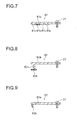
- Fig. 7 is a sectional view showing the structure of a diffusion-plate presser member of a backlight unit according to a third embodiment of the present invention.
- a description will be given of an example, as distinct from that in the above-described second embodiment, in which a projection 81 c is provided on a diffusion-plate presser member 81.
- the structure is similar to that in the above-described second embodiment.
- the diffusion-plate presser member 81 of the backlight unit comprises a plate member 81a and a catching member 81b.
- the plate member 81 a has projections 81c formed on its surface by drawing.
- the projections 81c are formed to have a curved surface extending in the direction perpendicular to the plane of the figure, and their surfaces make linear contact with the diffusion plate 22. Note that the projections 81c may be formed such that their surfaces make point contact with the diffusion plate 22.
- the plate member 81 a is provided with the projections 81c such that their surfaces make linear contact (or point contact) with the diffusion plate 22. This helps make the area small where the plate member 81a (projections 81c) keeps contact with the diffusion plate 22. Thus, it is possible to further prevent the squeaking noise even when the diffusion plate 22 moves (slides) with respect to the diffusion-plate presser member 81 due to a rise in temperature when the light sources 21 are lit.
- the third embodiment by forming the projections 81c on the plate member 81 a by drawing, it is possible to increase the solidity of the plate member 81a.
- Fig. 8 is a sectional view showing the structure of a diffusion-plate presser member of a backlight unit according to a fourth embodiment of the present invention.
- a description will be given of an example, as distinct from that in the above-described first embodiment, in which a diffusion-plate presser member 82 is provided with a compression spring 82c.
- the structure is similar to that in the above-described first embodiment.
- the diffusion-plate presser member 82 of the backlight unit comprises a plate member 82a, a catching member 82b, and a compression spring 82c arranged between the plate member 82a and the catching member 82b.
- the compression spring 82c is one example of "biasing means" according to the invention.
- the diffusion-plate presser member 82 is fixed to the support pedestal 25 with the compression spring 82c compressed. Specifically, by the biasing force of the compression spring 82c, the catching member 82b presses (biases) the diffusion plate 22 towards the support pedestal 25.
- the diffusion-plate presser member 82 is fixed to the support pedestal 25 with the compression spring 82c (catching member 82b) applying tension in the planar direction of the diffusion plate 22.
- the diffusion-plate presser member 82 is provided with the compression spring 82c that presses (biases) the diffusion plate 22 towards the support pedestal 25. This makes it possible to easily fix (support) the diffusion plate 22 in the direction perpendicular to the planar direction of the diffusion plate 22, and thus to easily prevent the diffusion plate 22 from deforming in the direction perpendicular to the planar direction of the diffusion plate 22. Moreover, by the diffusion-plate presser member 82 being provided with the compression spring 82c that biases the diffusion plate 22, it is possible to reduce variation in the pressing force of the diffusion-plate presser member 82, and thus to further prevent warping in the diffusion plate 22.
- the diffusion-plate presser member 82 being provided with the compression spring 82c, it is possible to easily engage the diffusion-plate presser member 82 with the catching part 22a of the diffusion plate 22 with tension applied in the planar direction of the diffusion plate 22.
- Fig. 9 is a sectional view showing the structure of a diffusion-plate presser member of a backlight unit according to a fifth embodiment of the present invention.
- a description will be given of an example, as distinct from that in the above-described first embodiment, in which a diffusion-plate presser member 83 is provided with a catching member 83b that has a curved shape.
- the structure is similar to that in the above-described first embodiment.
- the diffusion-plate presser member 83 of the backlight unit comprises a plate member 83a, and the catching member 83b which is curved in an arc shape and formed of resin, rubber, metal, or the like.
- the catching member 83b is one example of "biasing means" according to the invention.
- the catching member 83b is formed so as to curve in an arc shape, and thus it can be elastically deformed even when it is formed of metal.
- the diffusion-plate presser member 83 is fixed to the support pedestal 25 with the catching member 83b applying tension in the planar direction of the diffusion plate 22.
- the diffusion-plate presser member 83 is fixed to the support pedestal 25 with the catching member 83b compressed in the direction perpendicular to the planar direction of the diffusion plate 22. That is, by the biasing force (elastic force) of the catching member 83b, the catching member 83b presses (biases) the diffusion plate 22 toward the support pedestal 25.
- the catching member 83b of the diffusion-plate presser member 83 is formed to be elastically deformable. This makes it possible to easily engage the diffusion-plate presser member 83 with the catching part 22a of the diffusion plate 22 with tension applied in the planar direction of the diffusion plate 22. Moreover, the catching member 83b of the diffusion-plate presser member 83 is so formed as to press (bias) the diffusion plate 22 towards the support pedestal 25. This makes it possible to easily fix (support) the diffusion plate 22 in the direction perpendicular to the planar direction of the diffusion plate 22, and thus to easily prevent the diffusion plate 22 from deforming in the direction perpendicular to the planar direction of the diffusion plate 22.
- the diffusion-plate presser member 83 being provided with the catching member 83b that is curved in an arc shape and biases the diffusion plate 22, it is possible to reduce variation in the pressing force of the diffusion-plate presser member 83, and thus to further prevent warping in the diffusion plate 22.
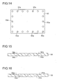
- Fig. 10 is a plan view showing the structure of a diffusion plate of a backlight unit according to a sixth embodiment of the present invention.
- a description will be given of an example, as distinct from that in the above-described first embodiment, in which two catching parts 90a are provided in a diffusion plate 90.
- the structure is similar to that in the above-described first embodiment.
- the diffusion plate 90 of the backlight unit according to the sixth embodiment of the invention has a rectangular shape as seen in a plan view, and the catching parts 90a are formed only at the two longer sides out of the four sides, forming the peripheral portion, of the rectangular shape. Note that the catching parts 90a may be formed only at the two shorter sides out of the four sides, forming the peripheral portion, of the rectangular shape.
- Fig. 11 is a plan view showing the structure of a diffusion plate of a backlight unit according to a seventh embodiment of the present invention.
- Fig. 12 is a sectional view showing the structure of the diffusion plate of the backlight unit according to the seventh embodiment shown in Fig. 11 .
- a description will be given of an example, as distinct from that in the above-described sixth embodiment, in which catching parts 91 a are formed in the front surface (upper surface) and the back surface (lower surface) of a diffusion plate 91, respectively.
- the structure is similar to that in the above-described sixth embodiment.
- the diffusion plate 91 of the backlight unit according to the seventh embodiment of the invention has a rectangular shape as seen in a plan view, and the catching parts 91a are formed only at the two longer sides out of the four sides, forming the peripheral portion, of the rectangular shape.
- one catching part 91 a is formed in the front surface (upper surface) of the diffusion plate 91 and the other catching part 91 a is formed in the back surface (lower surface) of the diffusion plate 91.
- the catching parts 91a may be formed only at the two shorter sides out of the four sides, forming the peripheral portion, of the rectangular shape of the diffusion plate 91.
- Fig. 13 is a plan view showing the structure of a diffusion plate of a backlight unit according to an eighth embodiment of the present invention.
- a description will be given of an example, as distinct from that in the above-described sixth embodiment, in which catching parts 92a are formed so as to reach the ends of a diffusion plate 92.
- the structure is similar to that in the above-described sixth embodiment.
- the diffusion, plate 92 of the backlight unit according to the eighth embodiment of the invention has a rectangular shape as seen in a plan view, and has the catching parts 92a formed only at the two longer sides out of the four sides, forming the peripheral portion, of the rectangular shape.
- the two catching parts 92a are formed such that their both ends reach the ends (of the two shorter sides) of the diffusion plate 92.
- the catching parts 92a may be formed only at the two shorter sides out of the four sides, forming the peripheral portion, of the rectangular shape of the diffusion plate 92.
- the two catching parts 92a As in the above-described seventh embodiment, it is possible to form one catching part 92a in the front surface (upper surface) of the diffusion plate 92, and the other catching part 92a in the back surface (lower surface) of the diffusion plate 92.
- Fig. 14 is a plan view showing the structure of a diffusion plate of a backlight unit according to a ninth embodiment of the present invention.
- a description will be given of an example, as distinct from that in the above-described first embodiment, in which a catching part 93a of a diffusion plate 93 has a circular shape.
- the structure is similar to that in the above-described first embodiment.
- the diffusion plate 93 of the backlight unit according to the ninth embodiment of the invention has a rectangular shape as seen in a plan view, and has a plurality of circular catching parts 93a formed at the four sides, forming the peripheral portion, of the rectangular shape.
- the plurality of catching parts 93a are arranged in a straight line along the peripheral portion of the diffusion plate 93.
- the catching parts 93a may be formed in a shape other than a circle; for example, they may be formed in an ellipse shape or a rectangular shape (square shape).
- the catching parts 93a may be formed only in corner parts of the diffusion plate 93, or be formed only in regions other than corner parts of the diffusion plate 93.
- Fig. 15 is a sectional view showing the structure of a diffusion plate of a backlight unit according to a tenth embodiment of the present invention.
- a description will be given of an example, as distinct from that in the above-described first embodiment, in which catching parts 94a are formed in the front surface (upper surface) and the back surface (lower surface) of a diffusion plate 94.
- the structure is similar to that in the above-described first embodiment.
- the catching parts 94a are formed not only in the front surface (upper surface) of the diffusion plate 94, but also in the back surface (lower surface) in regions at which catching parts 94a are formed in the front surface.
- the catching parts 94a in the back surface of the diffusion plate 94 may be formed to have the same width as the catching parts 94a in the front surface, or be formed to have a different width from them.
- the catching parts 94a in the back surface of the diffusion plate 94 may be formed to have the same depth as the catching parts 94a in the front surface, or be formed to have a different depth from them.
- sets of two diffusion-plate presser members may be arranged such that their catching members face each other, one set at each of the four sides, or the diffusion-plate presser member may be provided with two catching members that face each other.
- the catching parts 94a are formed not only in the front surface of the diffusion plate 94, but also in the back surface in regions at which the catching parts 94a are formed on the front surface. This makes it possible, by the diffusion-plate presser member, to fix the diffusion plate 94 with its being sandwiched in the top and bottom direction (the thickness direction). Thus, it is possible to prevent the diffusion-plate presser member from coming off from the catching parts 94a of the diffusion plate 94.
- Fig. 16 is a sectional view showing the structure of a diffusion plate of a backlight unit according to an eleventh embodiment of the present invention.
- a description will be given of an example, as distinct from that in the above-described tenth embodiment, in which catching parts 95a in the back surface (lower surface) of a diffusion plate 95 are arranged inward than catching parts 95a in the front surface (upper surface).
- the structure is similar to that in the above-described tenth embodiment.
- the catching parts 95a in the back surface of the diffusion plate 95 are arranged inward than the catching parts 95a in the front surface. In this way, when the diffusion plate 95 is likely to warp in an upward convex (or a downward convex) due to a rise in temperature when the light sources 21 are lit, it is possible to prevent the diffusion plate 95 from warping in an upward convex (or a downward convex).
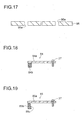
- Fig. 17 is a sectional view showing the structure of a diffusion plate of a backlight unit according to a twelfth embodiment of the present invention.
- Figs. 18 and 19 are sectional views showing the structure of a diffusion-plate presser member of the backlight unit according to the twelfth embodiment of the present invention.
- a description will be given of an example, as distinct from those in the above-described first, and sixth to ninth embodiments, in which catching parts 96a in a diffusion plate 96 are formed to be through holes.
- the structure is similar to those in the above described first, and sixth to ninth embodiments.
- the catching parts 96a are formed to be through holes that penetrate the diffusion plate 96 in the vertical direction (thickness direction).
- the catching parts 96a that penetrate the diffusion plate 96 are provided as described above, it is possible to use a diffusion plate presser member 84 shown in Fig. 18 . Specifically, it is possible to form the diffusion-plate presser member 84 with a plate member 84a and a catching member 84b having an equivalent length to the thickness of the diffusion plate 96. In this way, it is possible to prevent the diffusion-plate presser member 84 from coming off from the catching parts 96a of the diffusion plate 96.
- a diffusion-plate presser member 85 shown in Fig. 19 may be used.
- the diffusion-plate presser member 85 is formed with a plate member 85a and a catching member 85b having a length larger than the thickness of the diffusion plate 96, and a side surface 85c of the catching member 85b that makes contact with the diffusion plate 96 is formed to be a slanted surface.
- this diffusion-plate presser member 85 makes it possible to further prevent the diffusion-plate presser member 85 from coming off from the catching parts 96a of the diffusion plate 96.
- forming a side surface of the catching part 96a of the diffusion plate 96 that makes contact with the catching member 85b to be a slanted surface makes it possible to further prevent the diffusion-plate presser member 85 from coming off from the catching parts 96a.
Landscapes
- Physics & Mathematics (AREA)
- Nonlinear Science (AREA)
- Mathematical Physics (AREA)
- Chemical & Material Sciences (AREA)
- Crystallography & Structural Chemistry (AREA)
- General Physics & Mathematics (AREA)
- Optics & Photonics (AREA)
- Planar Illumination Modules (AREA)
- Liquid Crystal (AREA)
- Devices For Indicating Variable Information By Combining Individual Elements (AREA)
Abstract
Description
- The present invention relates to a backlight unit, a display unit, and a television receiver, and in particular the invention relates to a backlight unit, a display unit, and a television receiver, all of which are provided with a diffusion plate that diffuses light emitted from a light source.
- Conventionally, there are known backlight units provided with a diffusion plate that diffuses light emitted from a light source (e.g., see Patent Document 1). In Patent Document 1, a backlight unit is disclosed that is provided with fluorescent tubes (light sources), a diffusion plate diffusing light emitted from the fluorescent tubes and having holes (catching parts) in a peripheral portion thereof, and with pulling means engaging with the holes in the diffusion plate and applying tension to the diffusion plate in the planar direction.
- In such backlight units provided with fluorescent tubes (light sources) and a diffusion plate, generally, due to a rise in temperature when the fluorescent tubes are lit, a
diffusion plate 100 warps like a barrel (seeFig. 20 (a) and (b) ) or a saddle (seeFig. 21 (a) and (b) ), and in addition the peripheral portion moves inward in the planar direction. - In the backlight unit disclosed in Patent Document 1, by providing the pulling means that applies tension to the diffusion plate, it is possible to prevent the peripheral portion of the diffusion plate from moving inward in the planar direction, and thus to prevent, to a certain degree, warping in the diffusion plate caused by a rise in temperature when the fluorescent tubes are lit.
- Patent Document 1:
JP-A-2005-135670 - In the backlight unit disclosed in above-mentioned Patent Document 1, however, moving of the peripheral portion of the diffusion plate inward in the planar direction can be prevented indeed, but no mechanism is provided that fixes (supports) the diffusion plate in the direction perpendicular to the planar direction of the diffusion plate; thus, inconveniently, it is difficult to prevent the diffusion plate from deforming in the direction perpendicular to the planar direction of the diffusion plate. For this reason, there arises a problem where warping in the diffusion plate is difficult to prevent sufficiently. When warping occurs in the diffusion plate, inconveniently, there may be cases where the diffusion plate makes contact with a display panel, which is so arranged as to face the diffusion plate, and thus the surface pressure of the display panel varies, making it difficult to obtain satisfactory images, and where warping occurs also in an optical sheet, which is arranged on the diffusion plate, and thus achieving uniform brightness is made difficult.
- The present invention is devised to solve the above problems, and an object of the invention is to provide a backlight unit, a display unit, and a television receiver, all in which warping in a diffusion plate can be sufficiently prevented.
- To achieve the above object, according to a first aspect of the present invention, a backlight unit comprises: a light source; a diffusion plate diffusing light emitted from the light source and having a catching part in a peripheral portion thereof; a support pedestal supporting the diffusion plate; an optical sheet arranged on the diffusion plate; and a diffusion-plate presser member engaging with the catching part of the diffusion plate and sandwiching the diffusion plate between the support pedestal.
- In the backlight unit according to the first aspect, as described above, there are provided the diffusion plate having the catching part in the peripheral portion, and the diffusion-plate presser member engaging with the catching part of the diffusion plate. This makes it possible, by the diffusion-plate presser member, to prevent the peripheral portion of the diffusion plate from moving inward in the planar direction. Thus, it is possible to prevent warping in the diffusion plate caused by a rise in temperature when the light source is lit. Furthermore, there are provided the support pedestal that supports the diffusion plate, and the diffusion-plate presser member that sandwiches the diffusion plate between the support pedestal. This makes it possible to fix (support) the diffusion plate in the direction perpendicular to the planar direction of the diffusion plate. Thus, it is possible to prevent the diffusion plate from deforming in the direction perpendicular to the planar direction of the diffusion plate. In this way, warping in the diffusion plate can be sufficiently prevented. As a result, when a display panel is so arranged as to face the diffusion plate, it is possible to prevent the surface pressure of the display panel varying due to the diffusion plate making contact with the display panel, and thus satisfactory images can be obtained. Moreover, it is possible to prevent warping in the optical sheet that is arranged on the diffusion plate, and thus to achieve uniform brightness.
- Moreover, in the backlight unit according to the first aspect, as described above, there is provided the diffusion-plate presser member that engages with the catching part of the diffusion plate and sandwiches the diffusion plate between the support pedestal. This makes it possible, by the diffusion-plate presser member, to prevent the peripheral portion of the diffusion plate moving inward in the planar direction, and in addition to prevent the diffusion plate from deforming in the direction perpendicular to the planar direction of the diffusion plate. Thus, it is possible to prevent increased number of components, compared with a case in which separate members are provided for preventing the peripheral portion of the diffusion plate from moving inward in the planar direction, and for preventing the diffusion plate from deforming in the direction perpendicular to the planar direction of the diffusion plate.
- In the backlight unit according to the above-described first aspect, preferably, the catching part of the diffusion plate is formed so as to extend along the peripheral portion of the diffusion plate. With this structure, by the diffusion-plate presser member, moving of the peripheral portion of the diffusion plate inward in the planar direction can be prevented evenly, and in addition deforming of the diffusion plate in the direction perpendicular to the planar direction of the diffusion plate can be prevented evenly. Thus, warping in the diffusion plate can be prevented effectively.
- In the backlight unit according to the above-described first aspect, preferably, the diffusion-plate presser member is engaged with the catching part of the diffusion plate with tension applied in the planar direction of the diffusion plate. With this structure, it is possible to further prevent the peripheral portion of the diffusion plate moving inward in the planar direction. Thus, warping in the diffusion plate caused by a rise in temperature when the light source is lit can be further prevented.
- In this case, preferably, a part of the diffusion-plate presser member that engages with the catching part of the diffusion plate is formed to be elastically deformable. With this structure, it is possible to easily engage the diffusion-plate presser member with the catching part of the diffusion plate with tension applied in the planar direction of the diffusion plate.
- In the backlight unit according to the above-described first aspect, preferably, the diffusion-plate presser member sandwiches the diffusion plate between the support pedestal by pressing the diffusion plate, and the diffusion-plate presser member has biasing means that biases the diffusion plate in the direction in which the diffusion plate is pressed. With this structure, it is possible to easily fix (support) the diffusion plate in the direction perpendicular to the planar direction of the diffusion plate. Thus, it is possible to easily prevent the diffusion plate from deforming in the direction perpendicular to the planar direction of the diffusion plate.
- In the backlight unit according to the above-described first aspect, preferably, a part of the diffusion-plate presser member that makes contact with the diffusion plate is formed of resin. With this structure, when the diffusion plate moves (slides) with respect to the diffusion-plate presser member due to a rise in temperature when the light source is lit, it is possible to prevent the diffusion plate from being scratched, and to prevent squeaking noise. Moreover, the part of the diffusion-plate presser member that makes contact with the diffusion plate is formed of resin; thereby, it is possible to easily form the part of the diffusion-plate presser member that engages with the catching part of the diffusion plate elastically deformable.
- In the backlight unit according to the above-described first aspect, preferably, the diffusion-plate presser member is formed of metal or a metal compound. With this structure, a high solidity can be achieved in the diffusion-plate presser member, and thus it is possible to prevent the diffusion-plate presser member from deforming.
- In the backlight unit according to the above-described first aspect, preferably, the color of the surface of the diffusion-plate presser member is made white/whitish or black/blackish. With this structure, when the color of the surface of the diffusion-plate presser member is made white/whitish, by the light reflected at the surface of the diffusion-plate presser member, the brightness of the display panel can be enhanced; when the color of the surface of the diffusion-plate presser member is made black/blackish, it is possible to make the color of the outermost peripheral portion of the display panel black/blackish, and thus to have the diffusion-plate presser member serve as a frame of the display panel.
- According to a second aspect of the present invention, a display unit comprises the backlight unit described above, and a display panel illuminated by the backlight unit. With this structure, it is possible to obtain a display unit in which warping in a diffusion plate can be sufficiently prevented.
- In the display unit according to the above-described second aspect, preferably, the display panel has a liquid crystal display panel in which liquid crystal is sealed in between a pair of substrates. With this structure, it is possible to obtain a liquid crystal display unit in which warping in the diffusion plate can be sufficiently prevented.
- According to a third aspect of the present invention, a television receiver comprises the display unit described above, a cabinet housing the display unit, a tuner, and a speaker. With this structure, it is possible to obtain a television receiver in which warping in a diffusion plate can be sufficiently prevented.
- As described above, according to the present invention, it is possible to easily obtain a backlight unit, a display unit, and a television receiver, all in which warping in a diffusion plate can be sufficiently prevented.
-
- [
Fig. 1 ] An exploded perspective view showing the overall structure of a liquid crystal television receiver provided with a backlight unit according to a first embodiment of the present invention. - [
Fig. 2 ] A sectional view showing the structure of a liquid crystal display unit having the backlight unit according to the first embodiment of the invention. - [
Fig. 3 ] A plan view showing the structure of the backlight unit shown inFig. 2 around a diffusion plate. - [
Fig. 4 ] A plan view showing the structure of the diffusion plate of the backlight unit shown inFig. 2 . - [
Fig. 5 ] A sectional view showing the structure of a diffusion-plate presser member of the backlight unit shown inFig. 2 . - [
Fig. 6 ] A sectional view showing the structure of a diffusion-plate presser member of a backlight unit according to a second embodiment of the invention. - [
Fig. 7 ] A sectional view showing the structure of a diffusion-plate presser member of a backlight unit according to a third embodiment of the invention. - [
Fig. 8 ] A sectional view showing the structure of a diffusion-plate presser member of a backlight unit according to a fourth embodiment of the invention. - [
Fig. 9 ] A sectional view showing the structure of a diffusion-plate presser member of a backlight unit according to a fifth embodiment of the invention. - [
Fig. 10 ] A plan view showing the structure of a diffusion plate of a backlight unit according to a sixth embodiment of the invention. - [
Fig. 11 ] A plan view showing the structure of a diffusion plate of a backlight unit according to a seventh embodiment of the invention. - [
Fig. 12 ] A sectional view showing the structure of the diffusion plate of the backlight unit according to the seventh embodiment shown inFig. 11 . - [
Fig. 13 ] A plan view showing the structure of a diffusion plate of a backlight unit according to an eighth embodiment of the invention. - [
Fig. 14 ] A plan view showing the structure of a diffusion plate of a backlight unit according to a ninth embodiment of the invention. - [
Fig. 15 ] A sectional view showing the structure of a diffusion plate of a backlight unit according to a tenth embodiment of the invention. - [
Fig. 16 ] A sectional view showing the structure of a diffusion plate of a backlight unit according to an eleventh embodiment of the invention. - [
Fig. 17 ] A sectional view showing the structure of a diffusion plate of a backlight unit according to a twelfth embodiment of the invention. - [
Fig. 18 ] A sectional view showing the structure of a diffusion-plate presser member of the backlight unit according to the twelfth embodiment of the invention. - [
Fig. 19 ] A sectional view showing the structure of the diffusion-plate presser member of the backlight unit according to the twelfth embodiment of the invention. - [
Fig. 20 ] A perspective view showing a diffusion plate in a state where it is warped in a barrel shape. - [
Fig. 21 ] A perspective view showing a diffusion plate in a state where it is warped in a saddle shape. -
- 1
- liquid crystal television receiver (television receiver)
- 10
- liquid crystal display unit (display unit)
- 11
- liquid crystal display panel (display panel)
- 21
- light source
- 20
- backlight unit
- 22, 90, 91, 92, 93, 94, 95, 96
- diffusion plate
- 22a, 90a, 91a, 92a, 93a, 94a, 95a, 96a
- catching part
- 23
- optical sheet
- 25
- support pedestal
- 26, 80, 81, 82, 83, 84, 85
- diffusion-plate presser member
- 30
- front cabinet (cabinet)
- 31
- rear cabinet (cabinet)
- 40
- speaker
- 50
- tuner
- 82c
- compression spring (biasing means)
- 83b
- catching member (biasing means)
-
Fig. 1 is an exploded perspective view showing the overall structure of a liquid crystal television receiver provided with a backlight unit according to a first embodiment of the present invention.Fig. 2 is a sectional view showing the structure of a liquid crystal display unit having the backlight unit according to the first embodiment of the invention.Fig. 3 is a plan view showing the structure of the backlight unit shown inFig. 2 around a diffusion plate.Fig. 4 is a plan view showing the structure of the diffusion plate of the backlight unit shown inFig. 2 .Fig. 5 is a sectional view showing the structure of a diffusion-plate presser member of the backlight unit shown inFig. 2 . With reference toFigs. 1 to 5 , a description will be given of the structure of the liquid crystal television receiver 1 provided with thebacklight unit 20 according to the first embodiment of the present invention. Note that the liquid crystal television receiver 1 is one example of a "television receiver" according to the invention. - As shown in
Fig. 1 , the liquid crystal television receiver 1 that is provided with thebacklight unit 20 according to the first embodiment of the invention comprises: a liquidcrystal display unit 10 having thebacklight unit 20; afront cabinet 30 and arear cabinet 31 that house the liquidcrystal display unit 10;speakers 40 fitted to thefront cabinet 30; atuner 50; apower supply 60; and asupporter 70. For thefront cabinet 30, therear cabinet 31, thespeakers 40, thetuner 50, thepower supply 60, and thesupporter 70, those that have been conventionally used commonly can be applied; thus, they will be described briefly. Note that the liquidcrystal display unit 10 is one example of a "display unit" according to the invention, and thefront cabinet 30 and therear cabinet 31 are examples of a "cabinet" according to the invention. - The
front cabinet 30 and therear cabinet 31 house the liquidcrystal display unit 10, thetuner 50, and thepower supply 60, and are supported by thesupporter 70. Thetuner 50 has a function for generating an image signal and an audio signal of a predetermined channel from a radio wave received. Thespeaker 40 has a function for outputting sound based on the audio signal generated by thetuner 50. Thepower supply 60 is so designed as to feed electric power to the liquidcrystal display unit 10, thespeakers 40, and thetuner 50. Note that thespeakers 40, thetuner 50, and thepower supply 60 may be built into the liquidcrystal display unit 10. - As shown in
Fig. 2 , the liquidcrystal display unit 10 comprises: thebacklight unit 20; a liquidcrystal display panel 11 arranged at the front of thebacklight unit 20; and afront chassis 12 and aframe 13 that sandwich the liquidcrystal display panel 11 to support it. Note that the liquidcrystal display panel 11 is one example of a "display panel" according to the invention. - The liquid
crystal display panel 11 has pixels arrayed in a matrix. In addition, the liquidcrystal display panel 11 has a function for displaying images by being illuminated by thebacklight unit 20 and having the light from thebacklight unit 20 passing through it. Moreover, the liquidcrystal display panel 11 is formed with liquid crystal being sealed in between a pair of substrates. - The
backlight unit 20 comprises: a plurality oflight sources 21; adiffusion plate 22 that diffuses light emitted from thelight sources 21; anoptical sheet 23 arranged on the front surface of thediffusion plate 22; aback chassis 24 that covers thelight sources 21 and thediffusion plate 22 from behind; asupport pedestal 25 that supports thediffusion plate 22; and a diffusion-plate presser member 26 that sandwiches thediffusion plate 22 between thesupport pedestal 25. - The
light sources 21 are formed of a plurality of cylindrical fluorescent tubes arranged at a predetermined interval (period), and are fixed at the front of theback chassis 24. Note that thelight sources 21 may be formed of a meandering fluorescent tube. - The
diffusion plate 22 is formed of a plate-like transmissive member holding a diffusion member. In addition, thediffusion plate 22 is arranged so as to face the liquidcrystal display panel 11. - Here, in the first embodiment, as shown in
Figs. 2 and4 , thediffusion plate 22 has a rectangular shape as seen in a plan view, and catchingparts 22a - having a concave shape - are formed at the four sides, forming a peripheral portion, of the rectangular shape, one at each of the four sides. The catchingparts 22a are formed on the front surface (upper surface) of thediffusion plate 22. As shown inFig. 4 , the catchingparts 22a are formed such that two opposing catchingparts 22a are arranged in parallel. In addition, the catchingparts 22a have a narrow rectangular shape so as to extend along the peripheral portion of thediffusion plate 22. Note that the catchingparts 22a may be formed to have a shape other than rectangular; for example, they may be formed such that those at two opposing sides have an arc shape or the like, or may be formed to have a narrow elliptic shape. Moreover, the catchingparts 22a may be formed to have other shapes. - Moreover, in the first embodiment, each of the catching
parts 22a is formed such that both ends of the catchingpart 22a do not reach the ends (of the four sides) of thediffusion plate 22. - Moreover, in the first embodiment, as shown in
Fig. 2 , the catchingpart 22a is formed such that it has a depth smaller than the thickness of thediffusion plate 22. That is, the catchingpart 22a is formed such that it does not penetrate through thediffusion plate 22. - The
optical sheet 23 is formed of a prism sheet or a lens sheet, and has a function for focusing light from thediffusion plate 22 in a predetermined viewing angle. As shown inFig. 3 , theoptical sheet 23 has an area smaller than thediffusion plate 22, and is arranged inward than the diffusion-plate presser member 26. In addition, theoptical sheet 23 is held on the front surface (upper surface) of thediffusion plate 22 by an unillustrated optical-sheet presser member. Note that a gap may be provided between theoptical sheet 23 and the unillustrated optical-sheet presser member so that no pressing force acts on theoptical sheet 23. - As shown in
Fig. 2 , at the peripheral portion of theback chassis 24, thesupport pedestal 25 is fixed. Note that thesupport pedestal 25 may be formed integral with theback chassis 24. - In the
support pedestal 25, there are provided asupport surface 25a supporting the peripheral portion of thediffusion plate 22, and a threadedhole 25b to which ascrew 27 is fitted. - Moreover, in the first embodiment, as shown in
Fig. 5 , the diffusion-plate presser member 26 is formed of aplate member 26a - formed of metal - to which a plurality ofscrews 27 are fitted, and a catchingmember 26b formed of resin, rubber, or the like that can be elastically deformed. Note that theplate member 26a may be formed integral with the catchingmember 26b using resin, rubber, or the like, in which case highly solid resin, rubber, or the like is preferably used. The diffusion-plate presser member 26 may be formed of metal or a metal compound. In this case, it is possible to enhance the solidity of the diffusion-plate presser member 26, and thus possible to prevent deformation of the diffusion-plate presser member 26. - Moreover, in the first embodiment, the
plate member 26a of the diffusion-plate presser member 26 has a surface of which the color is white/whitish or black/blackish. - Moreover, in the first embodiment, as shown in
Figs. 2 and 3 , the diffusion-plate presser member 26 sandwiches thediffusion plate 22 between thesupport surface 25a (seeFig. 2 ) of thesupport pedestal 25, by theplate member 26a being fixed with the plurality ofscrews 27 screwed to the threadedholes 25b (seeFig. 2 ) of thesupport pedestal 25. In addition, it is preferable that the diffusion-plate presser member 26 be formed such that the catchingmember 26b presses the catchingpart 22a of thediffusion plate 22 toward thesupport pedestal 25. Moreover, the diffusion-plate presser member 26 may be formed such that the back surface (lower surface) of theplate member 26a presses thediffusion plate 22 toward thesupport pedestal 25. - Moreover, in the first embodiment, as shown in
Fig. 2 , the catchingmember 26b of the diffusion-plate presser member 26 is engaged with the catchingpart 22a of thediffusion plate 22 with tension applied in the planar direction (the direction indicated by an arrow A) of thediffusion plate 22. Specifically, the diffusion-plate presser member 26 is fixed with the outside surface of the catchingmember 26b of the diffusion-plate presser member 26 making contact with the inside surface of the catchingpart 22a of thediffusion plate 22, and thediffusion plate 22 is fixed with the peripheral portion being pulled outward. - In the first embodiment, as described above, there are provided the
diffusion plate 22 that has the catchingpart 22a at the peripheral portion, and the diffusion-plate presser member 26 that engages with the catchingpart 22a of thediffusion plate 22. This makes it possible to prevent the peripheral portion of thediffusion plate 22 from moving inward in the planar direction by the diffusion-plate presser member 26. Thus, it is possible to prevent warping in thediffusion plate 22 caused by a rise in temperature when thelight sources 21 are lit. Furthermore, there are provided thesupport pedestal 25 that supports thediffusion plate 22, and the diffusion-plate presser member 26 that sandwiches thediffusion plate 22 between thesupport pedestal 25. This makes it possible to fix (support) thediffusion plate 22 in the direction perpendicular to the planar direction of thediffusion plate 22. Thus, it is possible to prevent thediffusion plate 22 from deforming in the direction perpendicular to the planar direction of thediffusion plate 22. Thus, warping in thediffusion plate 22 can be sufficiently prevented. As a result, it is possible to prevent variation in the surface pressure of the liquidcrystal display panel 11 caused by the diffusion plate 22 (optical sheet 23) making contact with the liquidcrystal display panel 11, and thus to obtain satisfactory images. Moreover, it is possible to prevent warping in theoptical sheet 23 arranged on thediffusion plate 22, and thus to achieve uniform brightness. - Moreover, in the first embodiment, there is provided the diffusion-
plate presser member 26 that engages with the catchingpart 22a of thediffusion plate 22 and sandwiches thediffusion plate 22 between thesupport pedestal 25. This makes it possible, by the diffusion-plate presser member 26: to prevent the peripheral portion of thediffusion plate 22 moving inward in the planar direction; to prevent thediffusion plate 22 from deforming in the direction perpendicular to the planar direction of thediffusion plate 22; and to prevent increased number of components, compared with the case in which separate members are provided for preventing the peripheral portion of thediffusion plate 22 from moving inward in the planar direction, and for preventing thediffusion plate 22 from deforming in the direction perpendicular to the planar direction of thediffusion plate 22. - Moreover, in the first embodiment, the catching
part 22a of thediffusion plate 22 is formed so as to extend along the peripheral portion of thediffusion plate 22. This makes it possible, by the diffusion-plate presser member 26, to evenly prevent the peripheral portion of thediffusion plate 22 from moving toward the inner side in the planar direction, and to evenly prevent thediffusion plate 22 from deforming in the direction perpendicular to the planar direction of thediffusion plate 22. Thus, warping in thediffusion plate 22 can be prevented effectively. - Moreover, in the first embodiment, the catching
member 26b of the diffusion-plate presser member 26 is engaged with the catchingpart 22a of thediffusion plate 22 with tension applied in the planar direction of thediffusion plate 22. This makes it possible to further prevent the peripheral portion of thediffusion plate 22 from moving inward in the planar direction, and thus to further prevent warping in thediffusion plate 22 caused by a rise in temperature when thelight sources 21 are lit. - Moreover, in the first embodiment, the catching
member 26b of the diffusion-plate presser member 26 is formed of resin, rubber, or the like that can be elastically deformed. This makes it possible to easily engage the catchingmember 26b of the diffusion-plate presser member 26 with the catchingpart 22a of thediffusion plate 22 with tension applied to the planar direction of thediffusion plate 22. - Moreover, in the first embodiment, in a case where the catching
member 26b of the diffusion-plate presser member 26 is formed of resin, even if thediffusion plate 22 moves (slides) with respect to the diffusion-plate presser member 26 due to a rise in temperature when thelight sources 21 are lit, it is possible to prevent thediffusion plate 22 being scratched, and to prevent squeaking noise. - Moreover, in the first embodiment, the color of the surface of the diffusion-
plate presser member 26 is made white/whitish or black/blackish. In this way, when the color of the surface of the diffusion-plate presser member 26 is made white/whitish, by the light reflected at the surface of the diffusion-plate presser member 26, it is possible to enhance the brightness of the liquidcrystal display panel 11; when the color of the surface of the diffusion-plate presser member 26 is made black/blackish, it is possible to make the color of an outermost peripheral part of the liquidcrystal display panel 11 black/blackish, and thus to make the diffusion-plate presser member 26 serve as a frame of the liquidcrystal display panel 11. -
Fig. 6 is a sectional view showing the structure of a diffusion-plate presser member of a backlight unit according to a second embodiment of the present invention. In the second embodiment, with reference toFig. 6 , a description will be given of an example, as distinct from that in the above-described first embodiment, in which aresin plate 80c is provided in a diffusion-plate presser member 80. In other respects, the structure is similar to that in the above-described first embodiment. - As shown in
Fig. 6 , the diffusion-plate presser member 80 of the backlight unit according to the second embodiment of the invention comprises aplate member 80a, a catchingmember 80b, and theresin plate 80c. Theresin plate 80c is formed of resin with a smaller friction coefficient, for example, PET (polyethylene terephthalate), acrylic resin, PC (polycarbonate), or the like. Theresin plate 80c is fitted to theplate member 80a so as to make contact with thediffusion plate 22. In addition, theresin plate 80c is arranged at the inner side and the outer side of the catchingmember 80b. - In the second embodiment, as described above, the
resin plate 80c with a smaller friction coefficient is provided on theplate member 80a so as to make contact with thediffusion plate 22. In this way, when thediffusion plate 22 moves (slides) with respect to the diffusion-plate presser member 80 due to a rise in temperature when thelight sources 21 are lit, it is possible to prevent thediffusion plate 22 from being scratched and, to prevent squeaking noise. - In other respects, the effects of the second embodiment are similar to those of the above-described first embodiment.
-
Fig. 7 is a sectional view showing the structure of a diffusion-plate presser member of a backlight unit according to a third embodiment of the present invention. In the third embodiment, with reference toFig. 7 , a description will be given of an example, as distinct from that in the above-described second embodiment, in which a projection 81 c is provided on a diffusion-plate presser member 81. In other respects, the structure is similar to that in the above-described second embodiment. - As shown in
Fig. 7 , the diffusion-plate presser member 81 of the backlight unit according to the third embodiment of the invention comprises aplate member 81a and a catching member 81b. Theplate member 81 a has projections 81c formed on its surface by drawing. The projections 81c are formed to have a curved surface extending in the direction perpendicular to the plane of the figure, and their surfaces make linear contact with thediffusion plate 22. Note that the projections 81c may be formed such that their surfaces make point contact with thediffusion plate 22. - In the third embodiment, as described above, the
plate member 81 a is provided with the projections 81c such that their surfaces make linear contact (or point contact) with thediffusion plate 22. This helps make the area small where theplate member 81a (projections 81c) keeps contact with thediffusion plate 22. Thus, it is possible to further prevent the squeaking noise even when thediffusion plate 22 moves (slides) with respect to the diffusion-plate presser member 81 due to a rise in temperature when thelight sources 21 are lit. - Moreover, in the third embodiment, by forming the projections 81c on the
plate member 81 a by drawing, it is possible to increase the solidity of theplate member 81a. - In other respects, the effects of the third embodiment are similar to those of the above-described second embodiment.
-
Fig. 8 is a sectional view showing the structure of a diffusion-plate presser member of a backlight unit according to a fourth embodiment of the present invention. In the fourth embodiment, with reference toFig. 8 , a description will be given of an example, as distinct from that in the above-described first embodiment, in which a diffusion-plate presser member 82 is provided with acompression spring 82c. In other respects, the structure is similar to that in the above-described first embodiment. - As shown in
Fig. 8 , the diffusion-plate presser member 82 of the backlight unit according to the fourth embodiment of the invention comprises aplate member 82a, a catchingmember 82b, and acompression spring 82c arranged between theplate member 82a and the catchingmember 82b. Note that thecompression spring 82c is one example of "biasing means" according to the invention. The diffusion-plate presser member 82 is fixed to thesupport pedestal 25 with thecompression spring 82c compressed. Specifically, by the biasing force of thecompression spring 82c, the catchingmember 82b presses (biases) thediffusion plate 22 towards thesupport pedestal 25. In addition, the diffusion-plate presser member 82 is fixed to thesupport pedestal 25 with thecompression spring 82c (catchingmember 82b) applying tension in the planar direction of thediffusion plate 22. - In the fourth embodiment, as described above, the diffusion-
plate presser member 82 is provided with thecompression spring 82c that presses (biases) thediffusion plate 22 towards thesupport pedestal 25. This makes it possible to easily fix (support) thediffusion plate 22 in the direction perpendicular to the planar direction of thediffusion plate 22, and thus to easily prevent thediffusion plate 22 from deforming in the direction perpendicular to the planar direction of thediffusion plate 22. Moreover, by the diffusion-plate presser member 82 being provided with thecompression spring 82c that biases thediffusion plate 22, it is possible to reduce variation in the pressing force of the diffusion-plate presser member 82, and thus to further prevent warping in thediffusion plate 22. Moreover, by the diffusion-plate presser member 82 being provided with thecompression spring 82c, it is possible to easily engage the diffusion-plate presser member 82 with the catchingpart 22a of thediffusion plate 22 with tension applied in the planar direction of thediffusion plate 22. - In other respects, the effects of the fourth embodiment are similar to those of the above-described first embodiment.
-
Fig. 9 is a sectional view showing the structure of a diffusion-plate presser member of a backlight unit according to a fifth embodiment of the present invention. In the fifth embodiment, with reference toFig. 9 , a description will be given of an example, as distinct from that in the above-described first embodiment, in which a diffusion-plate presser member 83 is provided with a catchingmember 83b that has a curved shape. In other respects, the structure is similar to that in the above-described first embodiment. - As shown in
Fig. 9 , the diffusion-plate presser member 83 of the backlight unit according to the fifth embodiment of the invention comprises aplate member 83a, and the catchingmember 83b which is curved in an arc shape and formed of resin, rubber, metal, or the like. Note that the catchingmember 83b is one example of "biasing means" according to the invention. The catchingmember 83b is formed so as to curve in an arc shape, and thus it can be elastically deformed even when it is formed of metal. The diffusion-plate presser member 83 is fixed to thesupport pedestal 25 with the catchingmember 83b applying tension in the planar direction of thediffusion plate 22. In addition, the diffusion-plate presser member 83 is fixed to thesupport pedestal 25 with the catchingmember 83b compressed in the direction perpendicular to the planar direction of thediffusion plate 22. That is, by the biasing force (elastic force) of the catchingmember 83b, the catchingmember 83b presses (biases) thediffusion plate 22 toward thesupport pedestal 25. - In the fifth embodiment, as described above, the catching
member 83b of the diffusion-plate presser member 83 is formed to be elastically deformable. This makes it possible to easily engage the diffusion-plate presser member 83 with the catchingpart 22a of thediffusion plate 22 with tension applied in the planar direction of thediffusion plate 22. Moreover, the catchingmember 83b of the diffusion-plate presser member 83 is so formed as to press (bias) thediffusion plate 22 towards thesupport pedestal 25. This makes it possible to easily fix (support) thediffusion plate 22 in the direction perpendicular to the planar direction of thediffusion plate 22, and thus to easily prevent thediffusion plate 22 from deforming in the direction perpendicular to the planar direction of thediffusion plate 22. Moreover, by the diffusion-plate presser member 83 being provided with the catchingmember 83b that is curved in an arc shape and biases thediffusion plate 22, it is possible to reduce variation in the pressing force of the diffusion-plate presser member 83, and thus to further prevent warping in thediffusion plate 22. - In other respects, the effects of the fifth embodiment are similar to those of the above-described first embodiment.
-
Fig. 10 is a plan view showing the structure of a diffusion plate of a backlight unit according to a sixth embodiment of the present invention. In the sixth embodiment, with reference toFig. 10 , a description will be given of an example, as distinct from that in the above-described first embodiment, in which two catchingparts 90a are provided in adiffusion plate 90. In other respects, the structure is similar to that in the above-described first embodiment. - As shown in
Fig. 10 , thediffusion plate 90 of the backlight unit according to the sixth embodiment of the invention has a rectangular shape as seen in a plan view, and the catchingparts 90a are formed only at the two longer sides out of the four sides, forming the peripheral portion, of the rectangular shape. Note that the catchingparts 90a may be formed only at the two shorter sides out of the four sides, forming the peripheral portion, of the rectangular shape. - The effects of the sixth embodiment are similar to those of the above-described first embodiment.
-
Fig. 11 is a plan view showing the structure of a diffusion plate of a backlight unit according to a seventh embodiment of the present invention.Fig. 12 is a sectional view showing the structure of the diffusion plate of the backlight unit according to the seventh embodiment shown inFig. 11 . In the seventh embodiment, with reference toFigs. 11 and12 , a description will be given of an example, as distinct from that in the above-described sixth embodiment, in which catchingparts 91 a are formed in the front surface (upper surface) and the back surface (lower surface) of adiffusion plate 91, respectively. In other respects, the structure is similar to that in the above-described sixth embodiment. - As shown in
Fig. 11 , as in the above-described sixth embodiment, thediffusion plate 91 of the backlight unit according to the seventh embodiment of the invention has a rectangular shape as seen in a plan view, and the catchingparts 91a are formed only at the two longer sides out of the four sides, forming the peripheral portion, of the rectangular shape. In addition, as shown inFigs. 11 and12 , one catchingpart 91 a is formed in the front surface (upper surface) of thediffusion plate 91 and the other catchingpart 91 a is formed in the back surface (lower surface) of thediffusion plate 91. Note that the catchingparts 91a may be formed only at the two shorter sides out of the four sides, forming the peripheral portion, of the rectangular shape of thediffusion plate 91. - The effects of the seventh embodiment are similar to those of the above-described first embodiment.
-
Fig. 13 is a plan view showing the structure of a diffusion plate of a backlight unit according to an eighth embodiment of the present invention. In the eighth embodiment, with reference toFig. 13 , a description will be given of an example, as distinct from that in the above-described sixth embodiment, in which catchingparts 92a are formed so as to reach the ends of adiffusion plate 92. In other respects, the structure is similar to that in the above-described sixth embodiment. - As shown in
Fig. 13 , as in the above-described sixth embodiment the diffusion,plate 92 of the backlight unit according to the eighth embodiment of the invention has a rectangular shape as seen in a plan view, and has the catchingparts 92a formed only at the two longer sides out of the four sides, forming the peripheral portion, of the rectangular shape. The two catchingparts 92a are formed such that their both ends reach the ends (of the two shorter sides) of thediffusion plate 92. Note that the catchingparts 92a may be formed only at the two shorter sides out of the four sides, forming the peripheral portion, of the rectangular shape of thediffusion plate 92. With respect to the two catchingparts 92a, as in the above-described seventh embodiment, it is possible to form one catchingpart 92a in the front surface (upper surface) of thediffusion plate 92, and the other catchingpart 92a in the back surface (lower surface) of thediffusion plate 92. - The effects of the eighth embodiment are similar to those of the above-described first embodiment.
-
Fig. 14 is a plan view showing the structure of a diffusion plate of a backlight unit according to a ninth embodiment of the present invention. In the ninth embodiment, with reference toFig. 14 , a description will be given of an example, as distinct from that in the above-described first embodiment, in which a catchingpart 93a of adiffusion plate 93 has a circular shape. In other respects, the structure is similar to that in the above-described first embodiment. - As shown in
Fig. 14 , thediffusion plate 93 of the backlight unit according to the ninth embodiment of the invention has a rectangular shape as seen in a plan view, and has a plurality of circular catchingparts 93a formed at the four sides, forming the peripheral portion, of the rectangular shape. The plurality of catchingparts 93a are arranged in a straight line along the peripheral portion of thediffusion plate 93. Note that the catchingparts 93a may be formed in a shape other than a circle; for example, they may be formed in an ellipse shape or a rectangular shape (square shape). Moreover, the catchingparts 93a may be formed only in corner parts of thediffusion plate 93, or be formed only in regions other than corner parts of thediffusion plate 93. - The effects of the ninth embodiment are similar to those of the above-described first embodiment.
-
Fig. 15 is a sectional view showing the structure of a diffusion plate of a backlight unit according to a tenth embodiment of the present invention. In the tenth embodiment, with reference toFig. 15 , a description will be given of an example, as distinct from that in the above-described first embodiment, in which catchingparts 94a are formed in the front surface (upper surface) and the back surface (lower surface) of adiffusion plate 94. In other respects, the structure is similar to that in the above-described first embodiment. - As shown in
Fig. 15 , in thediffusion plate 94 of the backlight unit according to the tenth embodiment of the invention, the catchingparts 94a are formed not only in the front surface (upper surface) of thediffusion plate 94, but also in the back surface (lower surface) in regions at which catchingparts 94a are formed in the front surface. Note that the catchingparts 94a in the back surface of thediffusion plate 94 may be formed to have the same width as the catchingparts 94a in the front surface, or be formed to have a different width from them. Moreover, the catchingparts 94a in the back surface of thediffusion plate 94 may be formed to have the same depth as the catchingparts 94a in the front surface, or be formed to have a different depth from them. When such adiffusion plate 94 is used, sets of two diffusion-plate presser members may be arranged such that their catching members face each other, one set at each of the four sides, or the diffusion-plate presser member may be provided with two catching members that face each other. - In the tenth embodiment, as described above, the catching
parts 94a are formed not only in the front surface of thediffusion plate 94, but also in the back surface in regions at which the catchingparts 94a are formed on the front surface. This makes it possible, by the diffusion-plate presser member, to fix thediffusion plate 94 with its being sandwiched in the top and bottom direction (the thickness direction). Thus, it is possible to prevent the diffusion-plate presser member from coming off from the catchingparts 94a of thediffusion plate 94. - In other respects, the effects of the tenth embodiment are similar to those of the above-described first embodiment.
-
Fig. 16 is a sectional view showing the structure of a diffusion plate of a backlight unit according to an eleventh embodiment of the present invention. In the eleventh embodiment, with reference toFig. 16 , a description will be given of an example, as distinct from that in the above-described tenth embodiment, in which catchingparts 95a in the back surface (lower surface) of adiffusion plate 95 are arranged inward than catchingparts 95a in the front surface (upper surface). In other respects, the structure is similar to that in the above-described tenth embodiment. - As shown in
Fig. 16 , in thediffusion plate 95 of the backlight unit according to the eleventh embodiment of the invention, the catchingparts 95a in the back surface of thediffusion plate 95 are arranged inward than the catchingparts 95a in the front surface. In this way, when thediffusion plate 95 is likely to warp in an upward convex (or a downward convex) due to a rise in temperature when thelight sources 21 are lit, it is possible to prevent thediffusion plate 95 from warping in an upward convex (or a downward convex). - In other respects, the effects of the eleventh embodiment are similar to those of the above-described tenth embodiment.
-
Fig. 17 is a sectional view showing the structure of a diffusion plate of a backlight unit according to a twelfth embodiment of the present invention.Figs. 18 and 19 are sectional views showing the structure of a diffusion-plate presser member of the backlight unit according to the twelfth embodiment of the present invention. In the twelfth embodiment, with reference toFigs. 17 to 19 , a description will be given of an example, as distinct from those in the above-described first, and sixth to ninth embodiments, in which catchingparts 96a in adiffusion plate 96 are formed to be through holes. In other respects, the structure is similar to those in the above described first, and sixth to ninth embodiments. - As shown in
Fig. 17 , in thediffusion plate 96 of the backlight unit according to the twelfth embodiment of the present invention, the catchingparts 96a are formed to be through holes that penetrate thediffusion plate 96 in the vertical direction (thickness direction). - When the catching
parts 96a that penetrate thediffusion plate 96 are provided as described above, it is possible to use a diffusionplate presser member 84 shown inFig. 18 . Specifically, it is possible to form the diffusion-plate presser member 84 with aplate member 84a and a catchingmember 84b having an equivalent length to the thickness of thediffusion plate 96. In this way, it is possible to prevent the diffusion-plate presser member 84 from coming off from the catchingparts 96a of thediffusion plate 96. - Moreover, when the catching
parts 96a that penetrate through thediffusion plate 96 are provided, a diffusion-plate presser member 85 shown inFig. 19 may be used. Specifically, the diffusion-plate presser member 85 is formed with aplate member 85a and a catchingmember 85b having a length larger than the thickness of thediffusion plate 96, and aside surface 85c of the catchingmember 85b that makes contact with thediffusion plate 96 is formed to be a slanted surface. Using this diffusion-plate presser member 85 makes it possible to further prevent the diffusion-plate presser member 85 from coming off from the catchingparts 96a of thediffusion plate 96. Note that forming a side surface of the catchingpart 96a of thediffusion plate 96 that makes contact with the catchingmember 85b to be a slanted surface makes it possible to further prevent the diffusion-plate presser member 85 from coming off from the catchingparts 96a. - In other respects, the effects of the twelfth embodiment are similar to those of the above-described first embodiment.
- The embodiments disclosed herein are to be considered in all respects as illustrative and not restrictive. The scope of the present invention is set out in the appended claims and not in the description of the embodiments hereinabove, and includes any variations and modifications within the sense and scope equivalent to those of the claims.
- For example, although the above-described embodiments deal with an example in which a liquid crystal display panel, a liquid crystal display unit, and a liquid crystal television receiver are applied, respectively, for a display panel, a display unit, and a television receiver, this is not meant to limit the invention; it is also possible, instead, display panels, display units, and television receivers other than a liquid crystal display panel, a liquid crystal display unit, and a liquid crystal television receiver may be applied, respectively.
- Moreover, although the above-described embodiments deal with an example in which a diffusion-plate presser member is fixed to a support pedestal, this is not meant to limit the invention; it is also possible to fix the diffusion-plate presser member to elsewhere other than the support pedestal, for example, to a frame etc.
- Moreover, although the above-described embodiments deal with an example in which light sources are formed of fluorescent tubes, this is not meant to limit the invention; it is also possible to form the light sources with discharge tubes, LEDs, or the like.
Claims (11)
- A backlight unit comprising:a light source;a diffusion plate diffusing light emitted from the light source and having a catching part in a peripheral portion thereof;a support pedestal supporting the diffusion plate;an optical sheet arranged on the diffusion plate; anda diffusion-plate presser member engaging with the catching part of the diffusion plate and sandwiching the diffusion plate between the support pedestal.
- The backlight unit according to claim 1,
wherein the catching part of the diffusion plate is formed so as to extend along the peripheral portion of the diffusion plate. - The backlight unit according to claim 1,
wherein the diffusion-plate presser member is engaged with the catching part of the diffusion plate with tension applied in a planar direction of the diffusion plate. - The backlight unit according to claim 3,
wherein a part of the diffusion-plate presser member that engages with the catching part of the diffusion plate is formed to be elastically deformable. - The backlight unit according to claim 1,
wherein
the diffusion-plate presser member sandwiches the diffusion plate between the support pedestal by pressing the diffusion plate, and
the diffusion-plate presser member has biasing means that biases in a direction in which the diffusion plate is pressed. - The backlight unit according to claim 1,
wherein a part of the diffusion-plate presser member that makes contact with the diffusion plate is formed of resin. - The backlight unit according to claim 1,
wherein the diffusion-plate presser member is formed of metal or a metal compound. - The backlight unit according to claim 1,
wherein a color of a surface of the diffusion-plate presser member is made white/whitish or black/blackish. - A display unit comprising:the backlight unit according to any one of claims 1 to 8; anda display panel illuminated by the backlight unit.
- The display unit according to claim 9,
wherein the display panel has a liquid crystal display panel in which liquid crystal is sealed in between a pair of substrates. - A television receiver comprising:the display unit according to claim 9;a cabinet housing the display unit;a tuner; anda speaker.
Applications Claiming Priority (2)
| Application Number | Priority Date | Filing Date | Title |
|---|---|---|---|
| JP2007147685 | 2007-06-04 | ||
| PCT/JP2008/050568 WO2008149567A1 (en) | 2007-06-04 | 2008-01-18 | Backlight unit, display unit and television receiver |
Publications (2)
| Publication Number | Publication Date |
|---|---|
| EP2149740A1 true EP2149740A1 (en) | 2010-02-03 |
| EP2149740A4 EP2149740A4 (en) | 2010-05-12 |
Family
ID=40093396
Family Applications (1)
| Application Number | Title | Priority Date | Filing Date |
|---|---|---|---|
| EP08710558A Withdrawn EP2149740A4 (en) | 2007-06-04 | 2008-01-18 | Backlight unit, display unit and television receiver |
Country Status (5)
| Country | Link |
|---|---|
| US (1) | US8432504B2 (en) |
| EP (1) | EP2149740A4 (en) |
| JP (1) | JP4975814B2 (en) |
| CN (1) | CN101680614B (en) |
| WO (1) | WO2008149567A1 (en) |
Cited By (2)
| Publication number | Priority date | Publication date | Assignee | Title |
|---|---|---|---|---|
| CN102518997A (en) * | 2011-12-01 | 2012-06-27 | 青岛海信电器股份有限公司 | Backlight module and television |
| EP2631536A3 (en) * | 2012-02-23 | 2014-12-17 | LG Innotek Co., Ltd. | Illumination unit and display apparatus using the same |
Families Citing this family (2)
| Publication number | Priority date | Publication date | Assignee | Title |
|---|---|---|---|---|
| US20100208161A1 (en) * | 2009-02-19 | 2010-08-19 | Victor Company Of Japan, Limited | Backlight device and liquid crystal display |
| KR101762370B1 (en) * | 2011-02-01 | 2017-08-07 | 삼성디스플레이 주식회사 | Reflective and transparent type liquid crystal display device |
Family Cites Families (18)
| Publication number | Priority date | Publication date | Assignee | Title |
|---|---|---|---|---|
| JPH0545736A (en) | 1991-08-08 | 1993-02-26 | Mitsubishi Rayon Co Ltd | Extension support device for films and sheets |
| KR100258839B1 (en) * | 1998-01-24 | 2000-06-15 | 윤종용 | Lcd module |
| CN2500055Y (en) | 2000-03-15 | 2002-07-10 | 李荣欣 | Micro liquid crystal colour television |
| KR100640987B1 (en) * | 2000-10-14 | 2006-11-02 | 엘지.필립스 엘시디 주식회사 | Direct type backlight assembly of liquid crystal display |
| TW592324U (en) * | 2002-12-19 | 2004-06-11 | Coretronic Corp | Back light apparatus |
| JP2004219926A (en) * | 2003-01-17 | 2004-08-05 | Three M Innovative Properties Co | Optical film structure, lighting device and liquid crystal display device |
| JP2005044747A (en) * | 2003-07-25 | 2005-02-17 | Sumitomo Rubber Ind Ltd | Direct type backlight |
| JP4033828B2 (en) | 2003-10-29 | 2008-01-16 | シャープ株式会社 | Liquid crystal display device, backlight device |
| JP2005197142A (en) * | 2004-01-09 | 2005-07-21 | Sharp Corp | Backlight device |
| JP2005276718A (en) * | 2004-03-26 | 2005-10-06 | Sharp Corp | Backlight device |
| JP4084771B2 (en) | 2004-03-31 | 2008-04-30 | シャープ株式会社 | Backlight device |
| JP2006216512A (en) | 2005-02-07 | 2006-08-17 | Nippon Leiz Co Ltd | Flat lighting system |
| JP4327110B2 (en) * | 2005-02-23 | 2009-09-09 | シャープ株式会社 | Liquid crystal display |
| JP2007012569A (en) | 2005-07-04 | 2007-01-18 | Sony Corp | Backlight device and liquid crystal display device |
| JP2007080627A (en) | 2005-09-13 | 2007-03-29 | Nippon Leiz Co Ltd | Lighting device |
| US8031289B2 (en) * | 2005-09-22 | 2011-10-04 | Taisei Plas Co., Ltd. | Optical sheet retaining tool and chassis for liquid crystal display device |
| WO2007049379A1 (en) * | 2005-10-27 | 2007-05-03 | Sharp Kabushiki Kaisha | Structure for supporting optical sheet, illuminating device and display device |
| US8079725B2 (en) * | 2007-05-31 | 2011-12-20 | Sharp Kabushiki Kaisha | Display device and TV receiver |
-
2008
- 2008-01-18 WO PCT/JP2008/050568 patent/WO2008149567A1/en not_active Ceased
- 2008-01-18 JP JP2009517733A patent/JP4975814B2/en active Active
- 2008-01-18 US US12/602,665 patent/US8432504B2/en not_active Expired - Fee Related
- 2008-01-18 EP EP08710558A patent/EP2149740A4/en not_active Withdrawn
- 2008-01-18 CN CN200880017308XA patent/CN101680614B/en not_active Expired - Fee Related
Cited By (3)
| Publication number | Priority date | Publication date | Assignee | Title |
|---|---|---|---|---|
| CN102518997A (en) * | 2011-12-01 | 2012-06-27 | 青岛海信电器股份有限公司 | Backlight module and television |
| EP2631536A3 (en) * | 2012-02-23 | 2014-12-17 | LG Innotek Co., Ltd. | Illumination unit and display apparatus using the same |
| US8944624B2 (en) | 2012-02-23 | 2015-02-03 | Lg Innotek Co., Ltd. | Illumination unit and display apparatus using the same |
Also Published As
| Publication number | Publication date |
|---|---|
| CN101680614B (en) | 2011-08-03 |
| CN101680614A (en) | 2010-03-24 |
| JP4975814B2 (en) | 2012-07-11 |
| US20100177030A1 (en) | 2010-07-15 |
| WO2008149567A1 (en) | 2008-12-11 |
| JPWO2008149567A1 (en) | 2010-08-19 |
| EP2149740A4 (en) | 2010-05-12 |
| US8432504B2 (en) | 2013-04-30 |
Similar Documents
| Publication | Publication Date | Title |
|---|---|---|
| US7426106B2 (en) | Liquid crystal display device | |
| US10520666B2 (en) | Display device and television apparatus | |
| US7929073B2 (en) | Liquid crystal display module and method for assembling the same | |
| US20060034090A1 (en) | Backlight assembly | |
| CN101681058B (en) | Display device and television receiver | |
| JP2005158707A (en) | Backlight device and liquid crystal display device using the same | |
| US7131750B2 (en) | Backlight apparatus | |
| CN108881761A (en) | A kind of backboard, display module and display equipment | |
| US9541951B2 (en) | Display and television set | |
| JP3936895B2 (en) | Backlight device and liquid crystal display device | |
| CN102265086A (en) | Frame, light source device, display device, and television receiver | |
| CN104823101A (en) | Liquid crystal display device | |
| US8228458B2 (en) | Backlight unit and liquid crystal display | |
| US20090073675A1 (en) | Chassis for an illuminating unit, and an illuminating unit, a display device and a television receiver incorporating the chassis | |
| WO2011013405A1 (en) | Edge light type illuminating device, liquid crystal display device, television receiver, and method for manufacturing edge light type illuminating device | |
| EP2149740A1 (en) | Backlight unit, display unit and television receiver | |
| US9684123B2 (en) | Display device and television receiver | |
| WO2013191051A1 (en) | Display, and television receiver | |
| WO2009142057A1 (en) | Light source device and display device | |
| US8233106B2 (en) | Liquid crystal display device | |
| CN101784834B (en) | Illumination device for display device, display device, and television receiver | |
| US20180307085A1 (en) | Display device | |
| US20190113675A1 (en) | Light source device and display device | |
| KR101841572B1 (en) | Curved display apparatus for slim type | |
| KR102436466B1 (en) | Case member and liquid crystal display device comprising the same |
Legal Events
| Date | Code | Title | Description |
|---|---|---|---|
| PUAI | Public reference made under article 153(3) epc to a published international application that has entered the european phase |
Free format text: ORIGINAL CODE: 0009012 |
|
| 17P | Request for examination filed |
Effective date: 20091119 |
|
| AK | Designated contracting states |
Kind code of ref document: A1 Designated state(s): AT BE BG CH CY CZ DE DK EE ES FI FR GB GR HR HU IE IS IT LI LT LU LV MC MT NL NO PL PT RO SE SI SK TR |
|
| AX | Request for extension of the european patent |
Extension state: AL BA MK RS |
|
| A4 | Supplementary search report drawn up and despatched |
Effective date: 20100413 |
|
| DAX | Request for extension of the european patent (deleted) | ||
| GRAP | Despatch of communication of intention to grant a patent |
Free format text: ORIGINAL CODE: EPIDOSNIGR1 |
|
| RIC1 | Information provided on ipc code assigned before grant |
Ipc: G02F 1/1335 20060101ALI20150126BHEP Ipc: G02F 1/1333 20060101AFI20150126BHEP |
|
| INTG | Intention to grant announced |
Effective date: 20150213 |
|
| STAA | Information on the status of an ep patent application or granted ep patent |
Free format text: STATUS: THE APPLICATION IS DEEMED TO BE WITHDRAWN |
|
| 18D | Application deemed to be withdrawn |
Effective date: 20150624 |