EP2149714A1 - Cleaning assembly for removing wax from a bladed ring - Google Patents
Cleaning assembly for removing wax from a bladed ring Download PDFInfo
- Publication number
- EP2149714A1 EP2149714A1 EP09166649A EP09166649A EP2149714A1 EP 2149714 A1 EP2149714 A1 EP 2149714A1 EP 09166649 A EP09166649 A EP 09166649A EP 09166649 A EP09166649 A EP 09166649A EP 2149714 A1 EP2149714 A1 EP 2149714A1
- Authority
- EP
- European Patent Office
- Prior art keywords
- thrust
- wax
- axis
- assembly according
- bladed ring
- Prior art date
- Legal status (The legal status is an assumption and is not a legal conclusion. Google has not performed a legal analysis and makes no representation as to the accuracy of the status listed.)
- Withdrawn
Links
- 238000004140 cleaning Methods 0.000 title claims abstract description 11
- 230000014759 maintenance of location Effects 0.000 claims abstract description 5
- 230000008878 coupling Effects 0.000 claims description 6
- 238000010168 coupling process Methods 0.000 claims description 6
- 238000005859 coupling reaction Methods 0.000 claims description 6
- 230000000903 blocking effect Effects 0.000 claims description 4
- 230000000284 resting effect Effects 0.000 claims description 4
- 238000003825 pressing Methods 0.000 claims description 2
- 238000003754 machining Methods 0.000 description 3
- 230000005540 biological transmission Effects 0.000 description 1
- 238000010586 diagram Methods 0.000 description 1
- 238000007599 discharging Methods 0.000 description 1
- 239000012530 fluid Substances 0.000 description 1
- 238000010438 heat treatment Methods 0.000 description 1
- 238000000034 method Methods 0.000 description 1
- 239000011800 void material Substances 0.000 description 1
Images


Classifications
-
- F—MECHANICAL ENGINEERING; LIGHTING; HEATING; WEAPONS; BLASTING
- F04—POSITIVE - DISPLACEMENT MACHINES FOR LIQUIDS; PUMPS FOR LIQUIDS OR ELASTIC FLUIDS
- F04D—NON-POSITIVE-DISPLACEMENT PUMPS
- F04D29/00—Details, component parts, or accessories
- F04D29/70—Suction grids; Strainers; Dust separation; Cleaning
- F04D29/701—Suction grids; Strainers; Dust separation; Cleaning especially adapted for elastic fluid pumps
-
- B—PERFORMING OPERATIONS; TRANSPORTING
- B08—CLEANING
- B08B—CLEANING IN GENERAL; PREVENTION OF FOULING IN GENERAL
- B08B1/00—Cleaning by methods involving the use of tools
- B08B1/30—Cleaning by methods involving the use of tools by movement of cleaning members over a surface
-
- B—PERFORMING OPERATIONS; TRANSPORTING
- B08—CLEANING
- B08B—CLEANING IN GENERAL; PREVENTION OF FOULING IN GENERAL
- B08B9/00—Cleaning hollow articles by methods or apparatus specially adapted thereto
-
- F—MECHANICAL ENGINEERING; LIGHTING; HEATING; WEAPONS; BLASTING
- F01—MACHINES OR ENGINES IN GENERAL; ENGINE PLANTS IN GENERAL; STEAM ENGINES
- F01D—NON-POSITIVE DISPLACEMENT MACHINES OR ENGINES, e.g. STEAM TURBINES
- F01D25/00—Component parts, details, or accessories, not provided for in, or of interest apart from, other groups
- F01D25/002—Cleaning of turbomachines
-
- F—MECHANICAL ENGINEERING; LIGHTING; HEATING; WEAPONS; BLASTING
- F01—MACHINES OR ENGINES IN GENERAL; ENGINE PLANTS IN GENERAL; STEAM ENGINES
- F01D—NON-POSITIVE DISPLACEMENT MACHINES OR ENGINES, e.g. STEAM TURBINES
- F01D9/00—Stators
- F01D9/02—Nozzles; Nozzle boxes; Stator blades; Guide conduits, e.g. individual nozzles
- F01D9/04—Nozzles; Nozzle boxes; Stator blades; Guide conduits, e.g. individual nozzles forming ring or sector
- F01D9/042—Nozzles; Nozzle boxes; Stator blades; Guide conduits, e.g. individual nozzles forming ring or sector fixing blades to stators
-
- F—MECHANICAL ENGINEERING; LIGHTING; HEATING; WEAPONS; BLASTING
- F05—INDEXING SCHEMES RELATING TO ENGINES OR PUMPS IN VARIOUS SUBCLASSES OF CLASSES F01-F04
- F05D—INDEXING SCHEME FOR ASPECTS RELATING TO NON-POSITIVE-DISPLACEMENT MACHINES OR ENGINES, GAS-TURBINES OR JET-PROPULSION PLANTS
- F05D2230/00—Manufacture
- F05D2230/60—Assembly methods
- F05D2230/61—Assembly methods using limited numbers of standard modules which can be adapted by machining
Definitions
- the present invention relates to a cleaning assembly for removing wax from a bladed ring, in particular a bladed ring of a compressor stator.
- the stators of a gas turbine compressor each comprise a corresponding bladed ring having an inner annular wall, an outer annular wall and a series of blades fixed to these walls and spaced form one another in a circumferential direction.
- the wax is manually removed by striking a surface of the wax with a maul.
- these operations risk damaging the rings and/or blades if they are not carried out with the due care and take a relatively long time.
- the wax is detached from the bladed ring by heating in an furnace. This procedure is however relatively complex and expensive.
- a cleaning assembly for removing wax from a bladed ring is provided; the assembly being characterized by comprising:
- numeral 1 indicates as a whole a cleaning assembly for removing wax from a bladed ring 3 which belongs, in particular, to a compressor stator.
- Ring 3 comprises an outer cylindrical wall 5 and a plurality of blades 6, which have respective ends 7 fixed to the wall 5 in a known manner not described in detail, and are radially and overhangingly arranged towards the axis 8 of wall 5.
- Ring 3 may also comprise an inner cylindrical wall, fixed to the blades 6, at the opposite end with respect to the end 7.
- the blades 6 are spaced in a circumferential direction so as to define a series of compartments 9 therebetween which, in use, convey a fluid in an inclined direction with respect to a direction parallel to axis 8.
- Compartments 9 are at least partially filled with wax 10, to avoid vibrations and damages to the blades 6 while machining operations (known and not described in detail) carried out on the ring 3.
- Assembly 1 comprises a work bench 11, which comprises, in turn, a lower structure 12 defining a container 13 for receiving the pieces of wax 10 removed from the ring 3.
- Work bench 11 further comprises a plurality of bearings 14, which are carried by the structure 12 and are defined, in particular, by rollers for resting an axial face of the wall 5, so as to place the ring 3 with the axis 8 vertically oriented.
- the resting surface defined by the bearings 14 is higher than the upper surface 16 of the structure 12 to avoid any friction between the ring 3 and the surface 16 itself.
- work bench 11 further comprises a plurality of rollers 20, which are carried by the structure 12, may idly rotate about respective vertical axes 21, and define, as a whole, a rest for the outer cylindrical surface of the wall 5 and therefore a centring seat 22 for the ring 3.
- Bearings 14 may idly rotate about respective horizontal axes 15 radially directed with respect to the centre of the seat 22, while rollers 20 maintain the axis 8 in a substantially fixed position in the middle of the seat 22, whereby the ring 3 is pivoting about the axis 8 and may be manually pushed in rotation.
- an attachment structure 25 is arranged outside the seat 22.
- Structure 25 passes through an opening made in the surface 16, is fixed to the structure 12 in a manner not described in detail, possibly in an adjustable manner, and carries a vertical plate 26 facing the seat 22.
- Plate 26 is hinged to the structure 25 in a not illustrated manner in order to rotate about a horizontal axis 27, which is substantially radial with respect to the centre of the seat 22.
- Plate 26 is held in an angularly fixed position by a releasable blocking device 28, preferably comprising two parallel screws 29, which may slide within a slot 30 made in the plate 26, with an arc-shaped profile and centre coinciding with the axis 27, and are screwed into respective threaded holes 31 of the structure 25 to secure the plate 26 against the structure 25.
- Plate 26 carries an actuator 34 defined by a hydraulic or pneumatic jack, which comprises: a liner 36 fixed to the plate 26 by means of a bracket 37; and a stem 38 fluid-tightly coupled to the liner 36 so as to translate along an axis 39 orthogonal to axis 27 between an extracted position and a retracted position.
- Plate 26 has a window 40, through which a graduated scale 41 carried by the structure 25 may be seen.
- the graduated scale 41 indicates the inclination of the axis 39 with respect to the vertical, i.e. the angular position of the plate 26 about the axis 27.
- Stem 38 carries a thrust member 45 comprising a lower plate 46 and an upper attachment appendix 47, which is coupled to the lower end of the stem 38 by means of a hinge with cylindrical pin, so as to be able to freely rotate about a horizontal axis 48 orthogonal to axis 39, and directed in a substantially radial direction with respect to the centre of the seat 22.
- a thrust member 45 comprising a lower plate 46 and an upper attachment appendix 47, which is coupled to the lower end of the stem 38 by means of a hinge with cylindrical pin, so as to be able to freely rotate about a horizontal axis 48 orthogonal to axis 39, and directed in a substantially radial direction with respect to the centre of the seat 22.
- Thrust member 45 is chosen from a series of available thrust members, so as to have a plate 46 with dimensions such as to enter and exit from each compartment 9 along the axis 39 without touching the blades 6.
- the inclination of the axis 39 of jack 34 is adjusted by rotating the plate 26 about the axis 27 so as to make the axis 39 substantially coincide with the inclination of the blades 6 in the ring 3.
- any of the compartments 9 may be positioned to be aligned with the thrust member 45 along the axis 39 by rotating the ring 3 about the axis 8 on the rollers 14,20.
- each device 50 preferably comprises an actuator 51 and a stop element 52, which is actuated by the actuator 51 to move between a lowered position, in which it engages the wall 5 to block the ring 3, and a raised position (not shown), in which it leaves the ring 3 free to rotate on the rollers 14,20.
- the jack 34 is actuated so as to extract the stem 38 from the liner 36 and lower the thrust member 45.
- the plate 46 comes in contact with the upper surface 53 of the piece of wax 10 contained in the compartment 9 to be cleaned, and then pushes such a piece of wax downwards, until it is discharged into the container 13 underneath.
- the thrust member 45 automatically adapts its position about the axis 48 according to the orientation and shape of the surface 53.
- the jack 34 is actuated so as to retract the stem 38 back into the liner 36. Therefore, the thrust member 45 returns outside the newly cleaned compartment 9.
- the devices 50 are released, and the ring 3 is rotated about its axis 8 by an angle equal to the angular pitch between the compartments 9, so as to place a next compartment 9 to be cleaned in an aligned position with respect to the thrust member 45.
- the operations fro blocking ring 3 and actuating jack 34 are repeated to discharge the wax from the new compartment to be cleaned. In particular, the cleaning operations are repeated in a similar manner for all compartments 9, one after the other.
- the assembly 1 allows to reduce the risks of damaging the ring 3 and allows to reduce the cleaning time as compared to the known solutions in which cleaning is carried out by manually striking the wax with a maul, essentially by virtue of the use of an actuator and to the possibility of accurately positioning the ring 3 with respect to the thrust member 45.
- Assembly 1 is relatively cost-effective with respect to the use of a possible furnace for removing the wax, because it uses components and equipments which are individually easily available at low cost, and does not require high powers and/or complex control and safety systems.
- plate 46 Since it has a flat, substantially horizontal surface and/or a substantially horizontal, rectilinear edge at its bottom, plate 46 rests and distributes the pressure on a relatively large part of wax. Therefore, the thrust tends to detach the wax from the blades 6 without the plate 46 sinking into the wax, and thus effectively causes the discharging.
- the relative mobility in the coupling between the stem 38 and the thrust member 45 also allows the thrust member 45 to distribute the pressure without locally sinking into the wax at the time of contact.
- the thrust member 45 could have a different shape from that described and illustrated, e.g. it could be provided with one or more tips; and/or could be coupled to the lower end of the stem 38 in a different manner, e.g. in a fixed position or by means of other articulated joints different from the hinge indicated by way of example.
- An actuator different from a jack may be provided to displace the thrust member 45, e.g. an electric actuator and/or a rotary motor provided with a transmission which transforms the motion from rotational to translational; and/or several actuators arranged in positions spaced along the circular periphery of the ring 3 could be provided to simultaneously discharge the wax from a number of compartments 9, therefore over a shorter time.
- the thrust member 45 e.g. an electric actuator and/or a rotary motor provided with a transmission which transforms the motion from rotational to translational; and/or several actuators arranged in positions spaced along the circular periphery of the ring 3 could be provided to simultaneously discharge the wax from a number of compartments 9, therefore over a shorter time.
- Ring 3 could be rotated about its axis 8 in a motorized manner, instead of manually, e.g. by feeding through the actuation of the rollers 14 and/or 20; and/or could be supported by a piece-holder table which may rotate and be blocked by means of releasable retention means, instead of being supported by the rollers 14,20; and/or could be substantially fixed, but with a system for positioning the actuator 34 about the ring 3 at the various compartments 9 to be cleaned.
- the inclination of plate 25 could be adjusted by means of a guide or slot carried by the structure 25, instead of by means of the slot 30; or by means of adjustment devices which are distinct from the coupling of the structure 25, e.g. associated with the actuator which actuates the thrust members 45.
- the position of the rollers 14,20 and possibly of the devices 50 on the work bench 11 could be adjustable, so as to adapt the assembly 1 to rings 3 of different diameter.
Landscapes
- Engineering & Computer Science (AREA)
- Mechanical Engineering (AREA)
- General Engineering & Computer Science (AREA)
- Cleaning By Liquid Or Steam (AREA)
- Cleaning In General (AREA)
- Pallets (AREA)
- Adhesives Or Adhesive Processes (AREA)
Abstract
Description
- The present invention relates to a cleaning assembly for removing wax from a bladed ring, in particular a bladed ring of a compressor stator.
- The stators of a gas turbine compressor each comprise a corresponding bladed ring having an inner annular wall, an outer annular wall and a series of blades fixed to these walls and spaced form one another in a circumferential direction. Once the blades have been mounted, the two walls must be machined to obtain the dimensions and tolerances required in design. For machining, the void between the two walls is sealed by means of wax, in order to avoid damages to the blades. The wax is then removed after machining to obtain the finished ring to be mounted onto a casing of the compressor.
- According to a known solution, the wax is manually removed by striking a surface of the wax with a maul. However, these operations risk damaging the rings and/or blades if they are not carried out with the due care and take a relatively long time.
- According to another known solution, the wax is detached from the bladed ring by heating in an furnace. This procedure is however relatively complex and expensive.
- It is the object of the present invention to provide a cleaning assembly for removing wax from a bladed ring, which allows to simply and cost-effectively solve the aforementioned problems.
- According to the present invention, a cleaning assembly for removing wax from a bladed ring is provided; the assembly being characterized by comprising:
- supporting means for placing said bladed ring with its axis set vertically;
- a thrust member;
- angular-positioning means for rotating, with respect to one another, said bladed ring and said thrust member about the axis of said bladed ring;
- releasable retention means for blocking the relative rotation of said bladed ring and said thrust member; and
- actuator means controlled for displacing said thrust member in a direction of thrust and, in use, pressing the wax contained in a nozzle of said bladed ring.
- The invention will now be described with reference to the accompanying drawings which illustrate a non-limitative embodiment thereof, in which:
-
figure 1 is a diagram of a preferred embodiment of the cleaning assembly for removing wax from a bladed ring according to the present invention; -
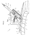
figures 2 and3 are perspective views which show respective details of the assembly infigure 1 on enlarged scale and in a simplified manner; and -
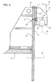
figure 4 is a cross section, on enlarged scale and with parts removed for clarity, taken along line IV-IV infigure 2 . - In
figures 1 and2 , numeral 1 indicates as a whole a cleaning assembly for removing wax from a bladed ring 3 which belongs, in particular, to a compressor stator. - Ring 3 comprises an outer
cylindrical wall 5 and a plurality of blades 6, which have respective ends 7 fixed to thewall 5 in a known manner not described in detail, and are radially and overhangingly arranged towards the axis 8 ofwall 5. Ring 3 may also comprise an inner cylindrical wall, fixed to the blades 6, at the opposite end with respect to the end 7. - The blades 6 are spaced in a circumferential direction so as to define a series of compartments 9 therebetween which, in use, convey a fluid in an inclined direction with respect to a direction parallel to axis 8. Compartments 9 are at least partially filled with
wax 10, to avoid vibrations and damages to the blades 6 while machining operations (known and not described in detail) carried out on the ring 3. - Assembly 1 comprises a
work bench 11, which comprises, in turn, alower structure 12 defining acontainer 13 for receiving the pieces ofwax 10 removed from the ring 3.Work bench 11 further comprises a plurality ofbearings 14, which are carried by thestructure 12 and are defined, in particular, by rollers for resting an axial face of thewall 5, so as to place the ring 3 with the axis 8 vertically oriented. The resting surface defined by thebearings 14 is higher than theupper surface 16 of thestructure 12 to avoid any friction between the ring 3 and thesurface 16 itself. - With reference to
figures 1 and3 ,work bench 11 further comprises a plurality ofrollers 20, which are carried by thestructure 12, may idly rotate about respectivevertical axes 21, and define, as a whole, a rest for the outer cylindrical surface of thewall 5 and therefore acentring seat 22 for the ring 3. -
Bearings 14 may idly rotate about respectivehorizontal axes 15 radially directed with respect to the centre of theseat 22, whilerollers 20 maintain the axis 8 in a substantially fixed position in the middle of theseat 22, whereby the ring 3 is pivoting about the axis 8 and may be manually pushed in rotation. - With reference to
figures 2 and4 , anattachment structure 25 is arranged outside theseat 22.Structure 25 passes through an opening made in thesurface 16, is fixed to thestructure 12 in a manner not described in detail, possibly in an adjustable manner, and carries avertical plate 26 facing theseat 22. -
Plate 26 is hinged to thestructure 25 in a not illustrated manner in order to rotate about ahorizontal axis 27, which is substantially radial with respect to the centre of theseat 22.Plate 26 is held in an angularly fixed position by areleasable blocking device 28, preferably comprising twoparallel screws 29, which may slide within aslot 30 made in theplate 26, with an arc-shaped profile and centre coinciding with theaxis 27, and are screwed into respective threadedholes 31 of thestructure 25 to secure theplate 26 against thestructure 25. -
Plate 26 carries anactuator 34 defined by a hydraulic or pneumatic jack, which comprises: aliner 36 fixed to theplate 26 by means of abracket 37; and astem 38 fluid-tightly coupled to theliner 36 so as to translate along anaxis 39 orthogonal toaxis 27 between an extracted position and a retracted position.Plate 26 has awindow 40, through which a graduatedscale 41 carried by thestructure 25 may be seen. The graduatedscale 41 indicates the inclination of theaxis 39 with respect to the vertical, i.e. the angular position of theplate 26 about theaxis 27. -
Stem 38 carries athrust member 45 comprising alower plate 46 and anupper attachment appendix 47, which is coupled to the lower end of thestem 38 by means of a hinge with cylindrical pin, so as to be able to freely rotate about ahorizontal axis 48 orthogonal toaxis 39, and directed in a substantially radial direction with respect to the centre of theseat 22. - The cylindrical pin of the hinge (not shown) is removable so as to be able to replace the
thrust member 45.Thrust member 45 is chosen from a series of available thrust members, so as to have aplate 46 with dimensions such as to enter and exit from each compartment 9 along theaxis 39 without touching the blades 6. At the same time, the inclination of theaxis 39 ofjack 34 is adjusted by rotating theplate 26 about theaxis 27 so as to make theaxis 39 substantially coincide with the inclination of the blades 6 in the ring 3. - Once these choices and/or adjustments have been made, any of the compartments 9 may be positioned to be aligned with the
thrust member 45 along theaxis 39 by rotating the ring 3 about the axis 8 on therollers - After positioning, the ring 3 is blocked by actuating one or more releasable retention devices 50 (
figure 3 ) carried by thestructure 12 over thesurface 16. Eachdevice 50 preferably comprises anactuator 51 and astop element 52, which is actuated by theactuator 51 to move between a lowered position, in which it engages thewall 5 to block the ring 3, and a raised position (not shown), in which it leaves the ring 3 free to rotate on therollers - Once ring 3 has been blocked, the
jack 34 is actuated so as to extract thestem 38 from theliner 36 and lower thethrust member 45. - During such a lowering, the
plate 46 comes in contact with theupper surface 53 of the piece ofwax 10 contained in the compartment 9 to be cleaned, and then pushes such a piece of wax downwards, until it is discharged into thecontainer 13 underneath. When resting theplate 46 on thesurface 53, by virtue of the hinge between thestem 38 and theappendix 47, thethrust member 45 automatically adapts its position about theaxis 48 according to the orientation and shape of thesurface 53. - Once the wax has been discharged from the compartment 9, the
jack 34 is actuated so as to retract thestem 38 back into theliner 36. Therefore, thethrust member 45 returns outside the newly cleaned compartment 9. - At this point, the
devices 50 are released, and the ring 3 is rotated about its axis 8 by an angle equal to the angular pitch between the compartments 9, so as to place a next compartment 9 to be cleaned in an aligned position with respect to thethrust member 45. The operations fro blocking ring 3 and actuatingjack 34 are repeated to discharge the wax from the new compartment to be cleaned. In particular, the cleaning operations are repeated in a similar manner for all compartments 9, one after the other. - From the above it is apparent that the assembly 1 allows to reduce the risks of damaging the ring 3 and allows to reduce the cleaning time as compared to the known solutions in which cleaning is carried out by manually striking the wax with a maul, essentially by virtue of the use of an actuator and to the possibility of accurately positioning the ring 3 with respect to the
thrust member 45. - Assembly 1 is relatively cost-effective with respect to the use of a possible furnace for removing the wax, because it uses components and equipments which are individually easily available at low cost, and does not require high powers and/or complex control and safety systems.
- The adjustment of the inclination of
plate 26 and the possibility of easily replacing thethrust member 45 allow to relatively quickly adapt the assembly 1 to different types of compartments 9. - Since it has a flat, substantially horizontal surface and/or a substantially horizontal, rectilinear edge at its bottom,
plate 46 rests and distributes the pressure on a relatively large part of wax. Therefore, the thrust tends to detach the wax from the blades 6 without theplate 46 sinking into the wax, and thus effectively causes the discharging. - The relative mobility in the coupling between the
stem 38 and thethrust member 45 also allows thethrust member 45 to distribute the pressure without locally sinking into the wax at the time of contact. - Finally, from the above, it is apparent that changes and variations may be made to the described assembly 1 without departing from the scope of protection of the present invention, as defined in the appended claims.
- In particular, the
thrust member 45 could have a different shape from that described and illustrated, e.g. it could be provided with one or more tips; and/or could be coupled to the lower end of thestem 38 in a different manner, e.g. in a fixed position or by means of other articulated joints different from the hinge indicated by way of example. - An actuator different from a jack may be provided to displace the
thrust member 45, e.g. an electric actuator and/or a rotary motor provided with a transmission which transforms the motion from rotational to translational; and/or several actuators arranged in positions spaced along the circular periphery of the ring 3 could be provided to simultaneously discharge the wax from a number of compartments 9, therefore over a shorter time. - Ring 3 could be rotated about its axis 8 in a motorized manner, instead of manually, e.g. by feeding through the actuation of the
rollers 14 and/or 20; and/or could be supported by a piece-holder table which may rotate and be blocked by means of releasable retention means, instead of being supported by therollers actuator 34 about the ring 3 at the various compartments 9 to be cleaned. - Furthermore, the inclination of
plate 25 could be adjusted by means of a guide or slot carried by thestructure 25, instead of by means of theslot 30; or by means of adjustment devices which are distinct from the coupling of thestructure 25, e.g. associated with the actuator which actuates thethrust members 45. - Finally, the position of the
rollers devices 50 on thework bench 11 could be adjustable, so as to adapt the assembly 1 to rings 3 of different diameter.
Claims (9)
- A cleaning assembly (1) for removing wax from a bladed ring (3); the assembly being characterized by comprising:- supporting means (14, 20) for placing said bladed ring with its axis (8) set vertically;- a thrust member (45);- angular-positioning means (15, 21) for rotating, with respect to one another, said bladed ring (3) and said thrust member (45) about the axis (8) of said bladed ring (3);- releasable retention means (50) for blocking the relative rotation of said bladed ring (3) and said thrust member (45); and- actuator means (34) controlled for displacing said thrust member (45) in a direction of thrust (39) and, in use, pressing the wax contained in a nozzle (9) of said bladed ring (3).
- The assembly according to Claim 1, characterized by comprising adjustment means (28) for varying the inclination of said direction of thrust (39) about a horizontal axis (27).
- The assembly according to Claim 2, characterized by comprising:- an attachment structure (25), and- coupling means for coupling said actuator means (34) to said attachment structure (25); said adjustment means (28) forming part of said coupling means.
- The assembly according to Claim 3, characterized in that said coupling means comprise:- a vertical plate (26) fixed to said actuator means (34) and coupled to said attachment structure (25) in such a way that it can turn about said horizontal axis (27);- a slot (30) made in one between said vertical plate (26) and said attachment structure (25); and- gripping means that are slidable in said slot and can be actuated for releasing/locking said vertical plate (26) with respect to said attachment structure (25).
- The assembly according to any one of the preceding claims, characterized in that said thrust member (45) comprises a bottom plate (46) having, for contact and thrust of said wax, a substantially horizontal bottom edge.
- The assembly according to Claim 5, characterized in that said bottom plate (46) has, for contact and thrust of said wax, a substantially horizontal bottom surface.
- The assembly according to Claim 5 or Claim 6, characterized in that said thrust member (45) comprises a top portion coupled to said actuator means (34) via a hinge so that it can turn about a horizontal hinge axis (48) orthogonal to said direction of thrust (39).
- The assembly according to any one of the preceding claims, characterized in that said actuator means (34) are defined by a linear actuator comprising a stem (38) that translates in said direction of thrust (39) and carries at one end thereof said thrust member (45).
- The assembly according to any one of the preceding claims, characterized in that said supporting means and said angular-positioning means, as a whole, are constituted by:- a plurality of resting rollers (14) that are able to turn about horizontal axes; and- a plurality of centring rollers (20) that are able to turn about vertical axes.
Applications Claiming Priority (1)
| Application Number | Priority Date | Filing Date | Title |
|---|---|---|---|
| ITTO2008A000602A IT1393990B1 (en) | 2008-07-31 | 2008-07-31 | CLEANING GROUP TO REMOVE WAX FROM A PALLET RING |
Publications (2)
| Publication Number | Publication Date |
|---|---|
| EP2149714A1 true EP2149714A1 (en) | 2010-02-03 |
| EP2149714A8 EP2149714A8 (en) | 2010-05-26 |
Family
ID=40934214
Family Applications (1)
| Application Number | Title | Priority Date | Filing Date |
|---|---|---|---|
| EP09166649A Withdrawn EP2149714A1 (en) | 2008-07-31 | 2009-07-28 | Cleaning assembly for removing wax from a bladed ring |
Country Status (2)
| Country | Link |
|---|---|
| EP (1) | EP2149714A1 (en) |
| IT (1) | IT1393990B1 (en) |
Cited By (4)
| Publication number | Priority date | Publication date | Assignee | Title |
|---|---|---|---|---|
| CN108005732A (en) * | 2017-12-20 | 2018-05-08 | 华瑞(江苏)燃机服务有限公司 | A kind of disassembly mechanism of gas turbine turbine stationary vane assembly |
| CN111617574A (en) * | 2020-05-21 | 2020-09-04 | 广西新天德能源有限公司 | A water film dust collector capable of on-line cleaning of induced draft fans and using method thereof |
| CN113206423A (en) * | 2021-04-29 | 2021-08-03 | 珠海格力智能装备有限公司 | Whitewashing device and power line production equipment with same |
| CN108655127B (en) * | 2017-04-01 | 2023-12-01 | 佛山市顺德区美的电热电器制造有限公司 | Method for cleaning electromagnetic oven pot |
Citations (4)
| Publication number | Priority date | Publication date | Assignee | Title |
|---|---|---|---|---|
| US5283020A (en) * | 1989-09-28 | 1994-02-01 | United Technologies Corporation | Component protection from contaminants |
| JPH1027683A (en) | 1996-07-10 | 1998-01-27 | Denki Kogyo Co Ltd | High frequency induction heating method for brazing material and high frequency induction heating apparatus |
| WO2002034465A1 (en) | 2000-10-25 | 2002-05-02 | Korea Institute Of Machinery & Materials | Method and apparatus for rapidly manufacturing 3-dimensional shaped products using machining and filling process |
| GB2382539A (en) | 2001-11-28 | 2003-06-04 | Alstom | Improved method of manufacture for hollow components |
-
2008
- 2008-07-31 IT ITTO2008A000602A patent/IT1393990B1/en active
-
2009
- 2009-07-28 EP EP09166649A patent/EP2149714A1/en not_active Withdrawn
Patent Citations (4)
| Publication number | Priority date | Publication date | Assignee | Title |
|---|---|---|---|---|
| US5283020A (en) * | 1989-09-28 | 1994-02-01 | United Technologies Corporation | Component protection from contaminants |
| JPH1027683A (en) | 1996-07-10 | 1998-01-27 | Denki Kogyo Co Ltd | High frequency induction heating method for brazing material and high frequency induction heating apparatus |
| WO2002034465A1 (en) | 2000-10-25 | 2002-05-02 | Korea Institute Of Machinery & Materials | Method and apparatus for rapidly manufacturing 3-dimensional shaped products using machining and filling process |
| GB2382539A (en) | 2001-11-28 | 2003-06-04 | Alstom | Improved method of manufacture for hollow components |
Cited By (5)
| Publication number | Priority date | Publication date | Assignee | Title |
|---|---|---|---|---|
| CN108655127B (en) * | 2017-04-01 | 2023-12-01 | 佛山市顺德区美的电热电器制造有限公司 | Method for cleaning electromagnetic oven pot |
| CN108005732A (en) * | 2017-12-20 | 2018-05-08 | 华瑞(江苏)燃机服务有限公司 | A kind of disassembly mechanism of gas turbine turbine stationary vane assembly |
| CN108005732B (en) * | 2017-12-20 | 2024-04-19 | 华瑞(江苏)燃机服务有限公司 | Dismounting mechanism of turbine stationary blade assembly of gas turbine |
| CN111617574A (en) * | 2020-05-21 | 2020-09-04 | 广西新天德能源有限公司 | A water film dust collector capable of on-line cleaning of induced draft fans and using method thereof |
| CN113206423A (en) * | 2021-04-29 | 2021-08-03 | 珠海格力智能装备有限公司 | Whitewashing device and power line production equipment with same |
Also Published As
| Publication number | Publication date |
|---|---|
| IT1393990B1 (en) | 2012-05-17 |
| EP2149714A8 (en) | 2010-05-26 |
| ITTO20080602A1 (en) | 2010-02-01 |
Similar Documents
| Publication | Publication Date | Title |
|---|---|---|
| JP6261611B2 (en) | Hydraulic cylinder assembly and disassembly equipment | |
| EP2149714A1 (en) | Cleaning assembly for removing wax from a bladed ring | |
| EP2565379B1 (en) | System and method for modifying a rotor | |
| US8453702B2 (en) | Device for blocking a wheel rim | |
| EP2535511A2 (en) | Apparatus and method for servicing dynamolectric machine components in-situ | |
| CN106470829B (en) | Rotary tablet press including turret and method of providing improved adjustment of parts thereof | |
| US20160279718A1 (en) | Milling tool for portion of slot in rotor | |
| CN104551942B (en) | For shortening the method and apparatus of the rotor blade of fluid machinery | |
| EP3017898A1 (en) | Attrition liner machining tool | |
| JP7760588B2 (en) | Method for replacing plain bearing pads arranged on the rotor shaft of a rotor bearing of a wind turbine | |
| EP3263888B1 (en) | Method of handling a wind turbine rotor blade pitch bearing unit | |
| US20190085827A1 (en) | Method for changing a bearing component and tool device for changing a bearing component | |
| EP3153266B1 (en) | Tube cutting device having conical fitting member to cut tube of waste steam generator and cutting method | |
| CN109909662B (en) | Welding table for impeller blades | |
| CN116967544A (en) | Pipeline electric spark dismantling and repairing equipment and pipeline electric spark dismantling and repairing method | |
| CN110665717B (en) | Brake disc spraying equipment | |
| JP5685402B2 (en) | Compressor equipment and tools | |
| EP2565390A1 (en) | Weld bead cutting device and method for extracting radial pin from steam turbine | |
| KR101857398B1 (en) | Cutting device | |
| CN105587777B (en) | Retainer installs contracting set all-in-one | |
| CN118789334B (en) | Positioning device and positioning method for processing thrust aligning roller bearing | |
| EP2335910B1 (en) | Loading apparatus and method of loading rolls of fibre based sheet material to an application unit | |
| EP2706198A1 (en) | Method for removing an inner casing from a machine | |
| KR101416334B1 (en) | Method and device for taking a sample in a steam generator | |
| JP2001071201A (en) | Processing equipment for cylindrical parts |
Legal Events
| Date | Code | Title | Description |
|---|---|---|---|
| PUAI | Public reference made under article 153(3) epc to a published international application that has entered the european phase |
Free format text: ORIGINAL CODE: 0009012 |
|
| AK | Designated contracting states |
Kind code of ref document: A1 Designated state(s): AT BE BG CH CY CZ DE DK EE ES FI FR GB GR HR HU IE IS IT LI LT LU LV MC MK MT NL NO PL PT RO SE SI SK SM TR |
|
| 17P | Request for examination filed |
Effective date: 20100726 |
|
| 17Q | First examination report despatched |
Effective date: 20100823 |
|
| GRAP | Despatch of communication of intention to grant a patent |
Free format text: ORIGINAL CODE: EPIDOSNIGR1 |
|
| RIC1 | Information provided on ipc code assigned before grant |
Ipc: F01D 9/04 20060101ALI20111223BHEP Ipc: B08B 1/00 20060101ALI20111223BHEP Ipc: B08B 9/00 20060101ALI20111223BHEP Ipc: F01D 25/00 20060101ALI20111223BHEP Ipc: F04D 29/70 20060101AFI20111223BHEP |
|
| RAP1 | Party data changed (applicant data changed or rights of an application transferred) |
Owner name: ANSALDO ENERGIA S.P.A. |
|
| GRAJ | Information related to disapproval of communication of intention to grant by the applicant or resumption of examination proceedings by the epo deleted |
Free format text: ORIGINAL CODE: EPIDOSDIGR1 |
|
| GRAP | Despatch of communication of intention to grant a patent |
Free format text: ORIGINAL CODE: EPIDOSNIGR1 |
|
| GRAJ | Information related to disapproval of communication of intention to grant by the applicant or resumption of examination proceedings by the epo deleted |
Free format text: ORIGINAL CODE: EPIDOSDIGR1 |
|
| GRAP | Despatch of communication of intention to grant a patent |
Free format text: ORIGINAL CODE: EPIDOSNIGR1 |
|
| STAA | Information on the status of an ep patent application or granted ep patent |
Free format text: STATUS: THE APPLICATION IS DEEMED TO BE WITHDRAWN |
|
| 18D | Application deemed to be withdrawn |
Effective date: 20130201 |