EP2149489A1 - Vehicle steering gear - Google Patents
Vehicle steering gear Download PDFInfo
- Publication number
- EP2149489A1 EP2149489A1 EP07744411A EP07744411A EP2149489A1 EP 2149489 A1 EP2149489 A1 EP 2149489A1 EP 07744411 A EP07744411 A EP 07744411A EP 07744411 A EP07744411 A EP 07744411A EP 2149489 A1 EP2149489 A1 EP 2149489A1
- Authority
- EP
- European Patent Office
- Prior art keywords
- electric motor
- steering angle
- failure
- driving
- steering
- Prior art date
- Legal status (The legal status is an assumption and is not a legal conclusion. Google has not performed a legal analysis and makes no representation as to the accuracy of the status listed.)
- Granted
Links
Images


Classifications
-
- B—PERFORMING OPERATIONS; TRANSPORTING
- B62—LAND VEHICLES FOR TRAVELLING OTHERWISE THAN ON RAILS
- B62D—MOTOR VEHICLES; TRAILERS
- B62D5/00—Power-assisted or power-driven steering
- B62D5/008—Changing the transfer ratio between the steering wheel and the steering gear by variable supply of energy, e.g. by using a superposition gear
-
- B—PERFORMING OPERATIONS; TRANSPORTING
- B62—LAND VEHICLES FOR TRAVELLING OTHERWISE THAN ON RAILS
- B62D—MOTOR VEHICLES; TRAILERS
- B62D6/00—Arrangements for automatically controlling steering depending on driving conditions sensed and responded to, e.g. control circuits
-
- B—PERFORMING OPERATIONS; TRANSPORTING
- B60—VEHICLES IN GENERAL
- B60R—VEHICLES, VEHICLE FITTINGS, OR VEHICLE PARTS, NOT OTHERWISE PROVIDED FOR
- B60R16/00—Electric or fluid circuits specially adapted for vehicles and not otherwise provided for; Arrangement of elements of electric or fluid circuits specially adapted for vehicles and not otherwise provided for
- B60R16/02—Electric or fluid circuits specially adapted for vehicles and not otherwise provided for; Arrangement of elements of electric or fluid circuits specially adapted for vehicles and not otherwise provided for electric constitutive elements
-
- B—PERFORMING OPERATIONS; TRANSPORTING
- B62—LAND VEHICLES FOR TRAVELLING OTHERWISE THAN ON RAILS
- B62D—MOTOR VEHICLES; TRAILERS
- B62D5/00—Power-assisted or power-driven steering
- B62D5/04—Power-assisted or power-driven steering electrical, e.g. using an electric servo-motor connected to, or forming part of, the steering gear
-
- B—PERFORMING OPERATIONS; TRANSPORTING
- B62—LAND VEHICLES FOR TRAVELLING OTHERWISE THAN ON RAILS
- B62D—MOTOR VEHICLES; TRAILERS
- B62D5/00—Power-assisted or power-driven steering
- B62D5/04—Power-assisted or power-driven steering electrical, e.g. using an electric servo-motor connected to, or forming part of, the steering gear
- B62D5/0457—Power-assisted or power-driven steering electrical, e.g. using an electric servo-motor connected to, or forming part of, the steering gear characterised by control features of the drive means as such
- B62D5/0481—Power-assisted or power-driven steering electrical, e.g. using an electric servo-motor connected to, or forming part of, the steering gear characterised by control features of the drive means as such monitoring the steering system, e.g. failures
Definitions
- the present invention relates to a steering apparatus for a vehicle which mechanically superposes an auxiliary steering angle on a driver's steering-wheel steering angle to steer road wheels by means of an auxiliary steering angle superposition mechanism using an electrically controllable electric motor.
- it relates to a technique that inhibits the rotation of an electric motor in an apparatus that performs intervention steering so as to correct the operation of the steering wheel by a driver, or in an apparatus that changes a transmission characteristic between the steering angle of the steering wheel operated by the driver and the steered angle of the steerable road wheels.
- the rotation of the electric motor is inhibited by driving on one-side transistors of upstream side and downstream side transistors of a transistor bridge circuit and driving off the other-side transistors thereof for the purpose of inhibiting the rotation of the electric motor.
- the present invention is intended to obviate the problem as referred to above, and hence to obtain a steering apparatus for a vehicle which is capable of quickly inhibiting the rotation of an electric motor without regard to the failure state of an electric motor driving unit or the like, whereby steerable road wheels can be steered in accordance with driver's steering operation of a steering wheel.
- a steering apparatus for a vehicle having a steering mechanism for steering steerable road wheels by means of a steering wheel that is operated by a driver and an auxiliary steering angle superposition mechanism by which an auxiliary steering angle can be superposed, includes: a transmission characteristic setting unit that sets a transmission characteristic between a steering angle of the steering wheel and a steering angle (steered angle) of steerable road wheels in accordance with a traveling condition of the vehicle; a steering wheel angle detection unit that detects a steering angle of the steering wheel operated by the driver; an auxiliary steering angle detection unit that detects an auxiliary steering angle to be steered by the auxiliary steering angle superposition mechanism or a steering angle detection unit that detects the steered angle of the steerable road wheels; a target driving amount calculation unit that generates a target auxiliary steering angle or a target steering angle added by the auxiliary steering angle superposition mechanism based on a steering-wheel steering angle detected value from the steering wheel angle detection unit and the transmission characteristic, and calculates a target amount of driving of the electric motor so as to
- the rotation of the electric motor can be inhibited in a quick manner without regard to the failure state of the electric motor driving unit or the like, whereby the steerable road wheels can be steered in accordance with driver's steering operation of the steering wheel.
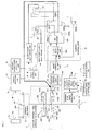
- Fig. 1 is a block diagram showing the general outline of a steering apparatus for a vehicle according to a first embodiment of the present invention.
- the steering apparatus for a vehicle is provided with a steering wheel 1 to which the driver of the vehicle applies a steering effort, an auxiliary steering angle superposition mechanism 2 that is connected with the steering wheel 1 and is subjected to free electrical control, a rack-and-pinion type steering mechanism 3 that is connected with the auxiliary steering angle superposition mechanism 2, knuckle arms 4a, 4b that are connected with the steering mechanism 3, steerable road wheels 5a, 5b that are connected with the knuckle arms 4a, 4b, respectively, a steering wheel angle detection unit 6 that detects an amount of steering (steering wheel angle ⁇ H ) of the steering wheel 1, a target auxiliary steering angle setting unit 7 that sets a target auxiliary steering angle based on the steering wheel angle ⁇ H , a transmission characteristic setting unit 8 that is connected to the target auxiliary steering angle setting unit 7, a vehicle travel state detection unit
- the auxiliary steering angle superposition mechanism 2 is composed, as an example, of a first planetary gear mechanism 201-205, a second planetary gear mechanism 206-209, and a shaft 210 that connects the two planetary gear mechanisms with each other, a worm gear 211 that is connected with the first planetary gear mechanism, and an electric motor (a motor) 212 that drives the worm gear 211 under the control of the current control unit 12.
- the first planetary gear mechanism is composed of a sun gear 201 that is connected with the steering wheel 1, planetary gears 202a, 202b that are supported by a carrier 203, a ring gear 204, and a worm wheel 205 for rotating the ring gear 204.
- the second planetary gear mechanism is composed of a sun gear 206, planetary gears 207a, 207b that are supported by a carrier 208, and a fixed ring gear 209.
- the carrier 203 of the first planetary gear mechanism and the carrier 208 of the second planetary gear mechanism are connected with each other through the shaft 210.
- the steering mechanism 3 is composed of a pinion gear 301, and a rack gear 302 that is in mesh with the pinion gear 301.
- the rotation of the pinion gear 301 is converted into a linear motion of the rack gear 302, and the linear motion of the rack gear 302 is converted into a steered angle of the steerable road wheels 5a, 5b through the knuckle arms 4a, 4b, respectively.
- the steering wheel angle detection unit 6 detects the steering angle of the steering wheel 1 that is steered by the driver, and inputs the steering wheel angle ⁇ H to the target auxiliary steering angle setting unit 7.
- the detected information from the vehicle travel state detection unit 9 is input to the transmission characteristic setting unit 8.
- the auxiliary steering angle detection unit 10 detects a rotational angle of the electric motor 212 substantially corresponding to the auxiliary steering angle ⁇ s, and inputs it to the target current setting unit 11.
- the target current setting unit 11 calculates a target current I REF for driving the electric motor 212 based on a target auxiliary steering angle ⁇ s REF from the target auxiliary steering angle setting unit 7 and the auxiliary steering angle ⁇ s from the auxiliary steering angle detection unit 10, and inputs it to the current control unit 12.
- the current control unit 12 is constructed of a duty ratio setting unit 1201, an FET driver 1202, an H bridge circuit (FETs 1203a - 1203d) driven by the FET driver 1202, and a current detection resistor 1204a, and a differential amplifier 1204b that differentially amplifies a voltage across opposite ends of the current detection resistor 1204a.
- the target current I REF from the target current setting unit 11 and a detected current Is from the differential amplifier 1204b are input to the duty ratio setting unit 1201.
- a duty ratio from the duty ratio setting unit 1201 and a control signal from the relay control unit 17 are input to the FET driver 1202.
- An output terminal of the H bridge circuit comprising the four FETs 1203a - 1203d is connected to the electric motor 212.
- the short-circuit relay 13 is driven by the short-circuit relay driving unit 14 to short-circuit the opposite terminals of the electric motor 212.
- the drive power supply relay 15 is driven by the drive power supply relay driving unit 16 to supply and interrupt the drive power to the current control unit 12.
- the failure detection unit 18 inputs a failure detection signal to the relay control unit 17 at the time of detecting the failure of various elements such as the auxiliary steering angle detection unit 10, the differential amplifier 1204b, etc., and upon detection of straight-ahead driving, the straight-ahead driving detection unit 19 inputs a detection signal to indicate a straight-ahead driving state to the relay control unit 17.
- the relay control unit 17 decides the operations of the short-circuit relay 13 and the drive power supply relay 15 in accordance with the kind of failure upon occurrence thereof as well as in accordance with the straight-ahead driving state.
- the short-circuit relay driving unit 14 and the drive power supply relay driving unit 16 control the operations of the short-circuit relay 13 and the drive power supply relay 15 in response to the control signal from the relay control unit 17.
- the rotation of the sun gear 201 is transmitted to the planetary gears 201 a, 201 b, but the ring gear 204 is fixed as previously stated, so the carrier 203 supporting the planetary gears 202a, 202b is caused to revolve around the sun gear, and the shaft 210 for the transmission of rotation to the second planetary gear mechanism is driven to rotate. That is, the first planetary gear mechanism acts as a planetary gear type speed reducer.
- the rotation of the shaft 210 is transmitted to the carrier 208 of the second planetary gear mechanism, whereby the planetary gears 207a, 207b are driven to revolve around the sun gear 206 in accordance with the rotation of the carrier 208.
- the ring gear 209 is fixed, so the revolutions of the planetary gears 207a, 207b cause the sun gear 206 to rotate, whereby the pinion gear 301 in the steering mechanism 3 is driven to rotate.
- the second planetary gear mechanism operates as a speed increasing gear, as viewed from the shaft 210. Accordingly, the rotation of the steering wheel 1 is mechanically transmitted to the pinion gear 301 with a transmission ratio of 1 : 1.
- the transmission ratio from the steering wheel 1 to the pinion gear 301 is a value which is obtained by multiplication of the speed reduction ratio of the first planetary gear mechanism and the speed reduction ratio (speed increasing ratio) of the second planetary gear mechanism, and if the constructions of the two planetary gear mechanisms are the same with respect to each other, the transmission ratio as a whole becomes "1". That is, in the mechanism of this first embodiment, if the rotation of the worm gear 211 is stopped, the steering wheel angle ⁇ H and the pinion angle of the steering mechanism 3 becomes "1 : 1 ", so it is found that an ordinary steering system is substantially constructed.
- the worm gear 211 is driven to rotate by the use of the electric motor 212 with the steering wheel 1 being fixed.
- the ring gear 204 is caused to rotate through the worm wheel 205.
- the rotation of the ring gear 204 is transmitted to the planetary gears 202a, 202b, but the sun gear 201 is fixed by the steering wheel 1, so the rotational torque to the planetary gears 202a, 202b is transmitted to the shaft 210 through the carrier 203 as the revolutions of the planetary gears 202a, 202b.
- the steering mechanism 3 is driven to steer the steerable road wheels 5a, 5b through the second planetary gear mechanism, as stated above.
- equation (1) can be transformed into the following equation (2).
- Fig. 2 is an explanatory view illustrating a characteristic of a target steering angle with respect to the steering wheel angle, wherein one example of a transmission characteristic f ( ⁇ H ) of the target steering angle (a target steered angle, a target pinion angle) ⁇ p REF with respect to the steering wheel angle ⁇ H is shown as a value corresponding to the vehicle speed.
- FIG. 3 is an explanatory view illustrating a characteristic of the target auxiliary steering angle with respect to the steering wheel angle, wherein one example of the transmission characteristic f ( ⁇ H ) of the target auxiliary steering angle ⁇ s REF to the steering wheel angle ⁇ H and one example of the characteristic of the mechanism are shown as values corresponding to the vehicle speed.
- Fig. 2 and Fig. 3 show the results obtained from the above equation (2) according to the following equations (3) and (4).
- the transmission characteristic setting unit 8 in Fig. 1 sets the transmission characteristic f ( ⁇ H ) in accordance with the vehicle speed which is one of the detected pieces of information from the vehicle travel state detection unit 9, and the target auxiliary steering angle setting unit 7 sets the target auxiliary steering angle ⁇ s REF from the steering wheel angle ⁇ H from the steering wheel angle detection unit 6 and the transmission characteristic f ( ⁇ H ) from the transmission characteristic setting unit 8.
- the auxiliary steering angle detection unit 10 detects the auxiliary steering angle ⁇ s
- the target current setting unit 11 calculates the target current I REF based on the target auxiliary steering angle ⁇ s REF and the auxiliary steering angle (the detected value) ⁇ s.
- Fig. 4 is a block diagram showing a construction example of the target current setting unit 11 and the duty ratio setting unit 1201.
- the target current setting unit 11 is provided with a subtracter 1101 that calculates an auxiliary steering angle deviation ⁇ s, an amplifier 1102 that amplifies the auxiliary steering angle deviation ⁇ s, a differentiator 1103a that differentiates the auxiliary steering angle deviation ⁇ s, an integrator 1104a that integrates the auxiliary steering angle deviation ⁇ s, amplifiers 1103b, 1104b that amplify a differentiated value and an integrated value, respectively, an adder 1105 that calculates a target torque T REF by adding the output values of the respective amplifiers 1102, 1103b, 1104b to one another, and a power amplifier 1106 that converts the target torque T REF into the target current I REF .
- a subtracter 1101 that calculates an auxiliary steering angle deviation ⁇ s
- an amplifier 1102 that amplifies the auxiliary steering angle deviation ⁇ s
- a differentiator 1103a that differentiates the auxiliary steering angle deviation ⁇ s
- an integrator 1104a that integrates the auxiliary steering angle deviation
- the duty ratio setting unit 1201 is provided with a subtracter 1201 a that calculates a current deviation ⁇ I, an amplifier 1201 b that amplifies the current deviation ⁇ I, an integrator 1201c that integrates the current deviation ⁇ I, amplifiers 1201d that amplify an integrated value, an adder 1201 e that calculates a target application voltage V M by adding the output values of the respective amplifiers 1201d, 1201 d to one another, and a duty ratio calculation unit 1201f that converts the target application voltage V M into the duty ratio.
- the differentiator 1103a differentiates the auxiliary steering angle deviation ⁇ s
- the amplifier 1103b multiplies the differentiated value from the differentiator 1103a by a differential gain KDp, and inputs it to the adder 1105.
- the integrator 1104a integrates the auxiliary steering angle deviation ⁇ s
- the amplifier 1104b multiplies the integrated value from the integrator 1104a by an integral gain KIp and inputs it to the adder 1105.
- the adder 1105 calculates the target torque T REF by adding three multiplication results of the respective amplifiers 1102, 1103b, 1104b to one another.
- the three gains (KPp, KDp and KIp) of the respective amplifiers 1102, 1103b, 1104b are set in an optimal manner in accordance with the frequency characteristic of the electric motor 212 in the case when the auxiliary steering angle is output with the generated torque of the electric motor 212 in the auxiliary steering angle superposition mechanism 2 being taken as an input.
- the output amplifier 1106 converts the target torque T REF into the target current I REF by using the relation of equation (5).
- the above-mentioned target current calculation processing is executed at each predetermined time (angle control period) in a repeated manner, whereby the target current I REF is sequentially updated and input to the current control unit 12.
- the operation of the duty ratio setting unit 1201 will be described below.
- the amplifier 1201 b inputs to the adder 1201 e a value that is obtained by multiplying the current deviation ⁇ I by the proportional gain KPi.
- the integrator 1201 c integrates the current deviation ⁇ I
- the amplifier 1201 d multiplies the integration result of the integrator 1201 c by the integral gain KIi, and inputs it to the adder 1201 e.
- the adder 1201 e calculates the target application voltage V M for the electric motor 212 by adding two multiplication results of the respective amplifiers 1201 b, 1201 d to each other.
- the duty ratio calculation unit 1201f calculates the duty ratio of the current supplied to the electric motor 212 by using the voltage of the drive power supply input to the current control unit 12 (electric motor driving unit). At this time, the duty ratio calculation unit 1201 f calculates the duty ratio in such a manner that the voltage applied to the electric motor 212 becomes substantially equal to the target application voltage V M as a result of driving the electric motor 212 based on the duty ratio thus set or calculated.
- the proportional gain KPi and the integral gain KIi of the respective amplifiers 1201 b and 1201 d are set based on the electrical characteristic of the electric motor 212 so as to make the current control characteristic suitable for controlling the auxiliary steering angle.
- the duty ratio output from the duty ratio setting unit 1201 is input to the FET driver 1202.
- the FET driver 1202 PWM controls the voltage applied to the electric motor 212 by on/off controlling four FETs 1203a, 1203b, 1203c, 1203d that together constitute the H bridge circuit, in accordance with the duty ratio.
- the differential amplifier 1204b detects as the detected current Is, a voltage generated across the opposite ends of the current detection resistor 1204a in the wiring extending from the current control unit 12 to the electric motor 212.
- the current control unit 12 controls the current flowing to the electric motor 212 by repeatedly executing the above-mentioned processing procedure at each predetermined time interval (current control period) in such a manner that the target current I REF (being sequentially updated at an angle control period) set by the target current setting unit 11 and the detected current Is coincide with each other.
- the current control processing by the current control unit 12 should control the current supplied to the electric motor 212 so as to coincide with the target current I REF until the next update after the target current I REF has been updated. Accordingly, it is desirable that the current control period of the current control unit 12 be set shorter than the angle control period of the target current setting unit 11. In addition, at this time, it is desirable that these two control periods (i.e., the current control period and the angle control period) be synchronized with each other, but the respective controls may be operated asynchronously with each other.
- the failure detection unit 18 stops the current supply to the electric motor 212 by cutting off the power supply to the current control unit 12 through the relay control unit 17 and the drive power supply relay driving unit 16.
- the failure detection unit 18 drives the short-circuit relay 13 through the relay control unit 17 and the short-circuit relay driving unit 14, so that the opposite terminals of the electric motor 212 are short-circuited, thereby electrically suppressing the rotation of the electric motor 212.
- the processing of stopping the current drive to the electric motor 212 is carried out by stopping the FET driver 1202 through the relay control unit 17 thereby to turn off all the FETs 1203a - 1203d, or by driving the drive power supply relay 15 through the relay control unit 17 and the drive power supply relay driving unit 16 thereby to interrupt the power supplied to the FETs 1203a - 1203d that together constitute the H bridge circuit.
- the steerable road wheels 5a, 5b can be steered in accordance with the driver's steering operation of the steering wheel.
- the target current setting unit 11 is constructed such that it should not output the target current I REF in excess of a maximum current that can be supplied to the electric motor 212.
- the polarity of the current deviation ⁇ I due to the subtracter 1201 a in the duty ratio setting unit 1201 constantly remains the same or unchanged without regard to the value of the target current I REF .
- the integrator 1201 c constantly integrates the current deviation ⁇ I of the same polarity, so the target application voltage V M sticks to the polarity in one direction, and hence the electric motor 212 operates to rotate only in either one direction (rotation failure).
- the failure detection unit 18 electrically suppresses the rotation failure of the electric motor 212 by stopping the current drive to the electric motor 212 through the relay control unit 17 and the drive power supply relay driving unit 16, and further by driving the short-circuit relay 13 through the short-circuit relay driving unit 14 thereby to short-circuit the opposite terminals of the electric motor 212.
- the steerable road wheels 5a, 5b can be steered in accordance with the driver's steering operation of the steering wheel.
- the electric motor 212 when the electric motor 212 is put into a freely rotatable state, the electric motor 212 tends to rotate freely even if the driver is strongly holding the steering wheel 1, so the steerable road wheels 5a, 5b are automatically steered toward a neutral point under the action of the self alignment torque generated during the travel of the vehicle.
- the short-circuit relay 13 is constructed in such a manner that it short-circuits the opposite terminals of the electric motor 212 when power is not supplied to the short-circuit relay 13. Accordingly, when the power supply is cut off, the short-circuit relay 13 is driven to move from the position shown in Fig. 1 to short-circuit the opposite terminals of the electric motor 212, so the idling failure of the electric motor 212 can be electrically suppressed. As a result, the steerable road wheels 5a, 5b can be steered in accordance with the driver's steering operation of the steering wheel.
- the failure detection unit 18 stops the current drive to the electric motor 212 through the relay control unit 17, and in addition, drives the short-circuit relay 13 through the short-circuit relay driving unit 14, so that the opposite terminals of the electric motor 212 are short-circuited, thereby electrically suppressing the idling failure of the electric motor 212.
- the steerable road wheels 5a, 5b can be steered in accordance with the driver's steering operation of the steering wheel.
- the detected current Is constantly becomes within the range of the target current I RE F due to the failure of the differential amplifier 1204b or the like.
- the target current I REF does not exceed the maximum current that can be supplied to the electric motor 212, as previously stated. Accordingly, when the detected current Is is put into an abnormality within the specified range thereof, the polarity of the current deviation ⁇ I (see Fig. 4 ) of the target current I REF based on the auxiliary steering angle deviation ⁇ s and the detected current Is within the specified range resulting from the failure substantially coincides with the polarity of the auxiliary steering angle deviation ⁇ s. That is, the driving direction of the electric motor 212 becomes coincident with the driving direction due to the target current setting unit 11.
- the drive current to the electric motor 212 is not controlled, so the electric motor 212 is driven to operate in a vibratory manner, but the vibration of the electric motor 212 is generated following the target auxiliary steering angle ⁇ s REF . Accordingly, even if the control of the electric motor 212 is continued as it is, the steerable road wheels 5a, 5b are not steered in a direction not intended by the driver. Therefore, even if the failure detection unit 18 detects an abnormality within the specified range of the detected current Is, the current control unit 12 need not be stopped urgently.
- the relay control unit 17 stops the current drive to the electric motor 212, and in addition, drives the short-circuit relay 13 through the short-circuit relay drivel unit 14, so that the opposite terminals of the electric motor 212 are short-circuited, thereby electrically suppressing the rotation of the electric motor 212.
- the auxiliary steering angle is controlled to "zero degrees" in the straight-ahead driving state, so the neutral point of the steering wheel 1 and the neutral point of the steerable road wheels 5a, 5b come to coincide with each other.
- the short-circuit relay 13 of the above-mentioned first embodiment ( Fig. 1 ) only acts to short-circuit the opposite terminals of the electric motor 212 at the time when a failure is detected, it may be constructed, as shown by a short-circuit relay 13A in Fig. 5 , such that upon detection of a failure, the opposite terminals of the electric motor 212 are short-circuited, and at the same time, current paths for the H bridge circuit (FETs 1203a - 1203d) and the electric motor 212 are interrupted.
- Fig. 5 is a block diagram showing a steering apparatus for a vehicle according to a second embodiment of the present invention, wherein parts similar to those described above (see Fig. 1 ) are identified by the same symbols or by the same symbols with "A" affixed to their ends, while omitting a detailed explanation thereof.
- the construction of Fig. 5 is different therefrom in the structure of the short-circuit relay 13A.
- the short-circuit relay 13 in Fig. 1 merely operates to short-circuit the opposite terminals of the electric motor 212
- the short-circuit relay 13A of Fig. 5 is switched from the illustrated state upon detection of a failure, so that it short-circuits the opposite terminals of the electric motor 212 and at the same time interrupts the paths to the H bridge circuit and the electric motor 212.
- the above-mentioned processing to stop the drive current to the electric motor 212 need not necessarily be executed.
- the rotation angle ⁇ M of the electric motor 212 (the auxiliary steering angle ⁇ s according to the auxiliary steering angle superposition mechanism 2) is controlled
- the steered angle of the steerable road wheels 5a, 5b can be practically controlled.
- the electric motor 212 can be driven so as to make the target steering angle ⁇ p REF (see Fig. 2 ) and an output value of the steering angle detection unit coincide with each other.
- any construction can be applied which is capable of superposing the auxiliary steering angle ⁇ s with respect to the steering of the steering wheel 1 (the steering wheel angle ⁇ H ).
- a mechanism for stopping the rotation of the electric motor 212 in a mechanical manner can be used together, as referred to in the aforementioned conventional apparatus.
- Fig. 6 shows a steering apparatus for a vehicle according to a third embodiment of the present invention, wherein parts similar to those described above (see Fig. 1 ) are identified by the same symbols or by the same symbols with "C" affixed to their ends, while omitting a detailed explanation thereof.
- the construction of Fig. 6 is different therefrom in that it has two systems which are arranged in parallel with each other, and which comprise relay control units 17A, 17B, failure detection units 18A, 18B, and straight-ahead driving detection units 19A, 19B, and is also different in the operations of a short-circuit relay driving unit 14C and a drive power supply relay driving unit 16C.
- the relay control unit 17A, the failure detection unit 18A and the straight-ahead driving detection unit 19A have identical functions to those of the relay control unit 17B, the failure detection unit 18B and the straight-ahead driving detection unit 19B, respectively. That is, the failure detection units 18A, 18B respectively detect failures independently from each other, and the straight-ahead driving detection units 19A, 19B also respectively detect straight-ahead driving states independently from each other.
- the relay control units 17A, 17B decide the operations of the short-circuit relay 13 and the drive power supply relay 15 through the short-circuit relay driving unit 14C and the drive power supply relay driving unit 16C in accordance with the kinds of failure detection signals from the failure detection units 18A, 18B, respectively, which are individually connected to the relay control units 17A, 17B, and in accordance with detection output signals from the straight-ahead driving detection units 19A, 19B, respectively, which are individually connected to the relay control units 17A, 17B.
- the short-circuit relay driving unit 14C switches the short-circuit relay 13 from its illustrated state thereby to short-circuit the opposite terminals of the electric motor 212.
- the drive power supply relay driving unit 16C switches the drive power supply relay 15 from its illustrated state thereby to interrupt the drive power supply to the H bridge circuit.
- an A system 17A - 19A and a B system 17B - 19B be formed of separate CPUs (not shown), respectively, so as to ensure a dual system.
- the A system and the B system are formed of separate CPUs, respectively, individual independent input circuits of the CPUs are used for the individual failure detection units 18A, 18B, respectively, so in particular, the reliability of failure detection for the input circuits is improved.
- the short-circuit relay 13 can be constructed such that it short-circuits the opposite terminals of the electric motor 212 and at the same time interrupts the power supply paths to the H bridge circuit and the electric motor 212, as in the above-mentioned second embodiment ( Fig. 5 ).
- a three-phase DC brushless motor can be used as the electric motor 212, and the steering angle of the steerable road wheels 5a, 5b can be controlled in place of the angle control of the electric motor 212.
- any kind of mechanism can be used as the auxiliary steering angle superposition mechanism 2, and a mechanism for stopping the rotation of the electric motor 212 in a mechanical manner can be used together, as in the aforementioned conventional apparatus.
- the steering apparatus for a vehicle which has the steering mechanism 3 for steering the steerable road wheels 5a, 5b by means of the steering wheel 1 that is operated by the driver and the auxiliary steering angle superposition mechanism 2 by which an auxiliary steering angle can be superposed, includes: the transmission characteristic setting unit 8 that sets the transmission characteristic f ( ⁇ H ) between the steering angle of the steering wheel 1 and the steered angle of the steerable road wheels 5a, 5b in accordance with the traveling condition of the vehicle; the steering wheel angle detection unit 6 that detects the steering-wheel steering angle (steering wheel angle ⁇ H ) of the steering wheel 1 operated by the driver; and the auxiliary steering angle detection unit 10 that detects the auxiliary steering angle ⁇ s to be steered by the auxiliary steering angle superposition mechanism 2 (or the steering angle detection unit that detects the steered angle of the steerable road wheels).
- the transmission characteristic setting unit 8 that sets the transmission characteristic f ( ⁇ H ) between the steering angle of the steering wheel 1 and the steered angle of the steerable road wheels 5a
- the steering apparatus for a vehicle further includes the target driving amount calculation unit (the target current setting unit 11) that generates the target auxiliary steering angle ⁇ s REF (or the target steering angle) added by the auxiliary steering angle superposition mechanism 2 based on the steering-wheel steering angle detected value (the steering wheel angle ⁇ H ) from the steering wheel angle detection unit 6 and the transmission characteristic f ( ⁇ H ), and calculates the target amount of driving of the electric motor 212 (the target current I REF ) so as to make the target auxiliary steering angle ⁇ s REF and the auxiliary steering angle ⁇ s (the detected value) from the auxiliary steering angle detection unit 10 coincide with each other (or so as to make the target steering angle and the steering angle detected value from the steering angle detection unit coincide with each other).
- the target driving amount calculation unit the target current setting unit 11
- the steering apparatus for a vehicle includes: the electric motor driving unit (the current control unit 12) that drives the electric motor 212 in accordance with the target amount of driving; and the relay unit (the short-circuit relay 13 and the drive power supply relay 15) that inhibits the rotation of the electric motor 212 by short-circuiting the opposite terminals of the electric motor 212 under a predetermined condition.
- the rotation of the electric motor can be inhibited in a quick manner without regard to the failure state of the electric motor driving unit, whereby the steerable road wheels can be steered in accordance with driver's steering operation of the steering wheel.
- the short-circuit relay 13 can operate, without power supply, to short-circuit the opposite terminals of the electric motor 212.
- the relay unit (the short-circuit relay 13 and the drive power supply relay 15) is constructed to switch an electrical connection operation to the electric motor 212 in addition to performing the operation of short-circuiting the opposite terminals of the electric motor 212, so that it performs cutting off the drive current to the electric motor 212 and short-circuiting the opposite terminals thereof at the same time.
- the rotation of the electric motor 212 can be inhibited in a quick manner without regard to the state of the electric motor driving unit, whereby the steerable road wheels can be steered in accordance with driver's steering operation of the steering wheel.
- the relay unit is constructed in such a manner that it short-circuits the opposite terminals of the electric motor when the power supply to the relay unit is cut off.
- the failure detection unit 18 (18A, 18B) that detects at least the failure of the electric motor driving unit (the current control unit 12), and the operation of the relay unit is controlled in accordance with the kind of the failure detected by the failure detection unit.
- the rotation of the electric motor 212 can be inhibited in a quick manner upon detection of the failure, whereby the steerable road wheels can be steered in accordance with driver's steering operation of the steering wheel.
- the relay unit operates to stop the driving of the electric motor 212, and at the same time short-circuit the opposite terminals of the electric motor 212, as a result of which the rotation failure of the electric motor 212 can be inhibited in a quick manner upon detection of the failure, whereby the steerable road wheels can be steered in accordance with driver's steering operation of the steering wheel.
- the rotation failure of the electric motor 212 is a failure of the auxiliary steering angle detection unit 10 at the time when the target driving amount calculation unit (the target current setting unit 11) calculates the target amount of driving (the target current I REF ) so as to make the target auxiliary steering angle ⁇ s REF and the auxiliary steering angle ⁇ s (the detected value) coincide with each other.
- the rotation failure of the electric motor 212 is a failure in which an excessive amount of driving in one rotational direction with respect to the electric motor 212 is generated due to the failure of the steering angle detection unit or the failure of the electric motor driving unit (the current control unit 12) at the time when the target driving amount calculation unit calculates the target amount of driving so as to make the target steering angle and the steering angle detected value coincide with each other.
- the idling failure of the electric motor 212 is a failure in which electric current can not be supplied to the electric motor 212 due to the failure of the electric motor driving unit (the current control unit 12).
- the relay unit operates to short-circuit the opposite terminals of the electric motor 212 in case where any of the above-mentioned various kinds of failures is detected by the failure detection unit 18, so the rotation failure of the electric motor 212 can be inhibited in a quick manner upon occurrence of a failure, whereby the steerable road wheels can be steered in accordance with driver's steering operation of the steering wheel.
- the straight-ahead driving detection unit 19 (19A and 19B) which detects that the vehicle is in a straight-ahead driving state, and the relay unit operates to continue the driving control of the auxiliary steering angle superposition mechanism 2 when the non-rotation failure of the electric motor 212 (failure to rotate on its own axis) is detected by the failure detection unit 18, and in addition, stop the driving of the electric motor 212 and at the same time short-circuit the opposite terminals of the electric motor 212 when it is detected by the straight-ahead driving detection unit 19 that the vehicle is in the straight-ahead driving state.
- the driving control of the auxiliary steering angle superposition mechanism 2 until the vehicle is put into a straight-ahead driving state there occurs no sudden change of steering in the steerable road wheels 5a, 5b with respect to the driver's steering operation of the steering wheel.
- the rotation of the electric motor 212 is inhibited when the vehicle is in the straight-ahead driving state, and hence the steerable road wheels can be steered in accordance with the steering operation of the steering wheel with the neutral point of the steering wheel 1 and the neutral point of the steerable road wheels 5a, 5b being made to coincide with each other.
- the non-rotation failure of the electric motor 212 is a failure in which an excessive amount of driving (drive current I M ) though the direction of driving being correct is generated with respect to the electric motor 212 resulting from the failure of the electric motor driving unit (the current control unit 12).
- the relay unit operates to short-circuit the opposite terminals of the electric motor 212, so upon occurrence of the non-rotation failure, the rotation of the electric motor 212 can be inhibited in a quick manner, whereby the steerable road wheels can be steered in accordance with driver's steering operation of the steering wheel.
- the failure detection unit comprises the plurality of failure detection units 18A, 18B (see Fig. 6 ) which are arranged in parallel to each other and are independent from each other, and each of the plurality of failure detection units 18A, 18B detects the same failure.
- the failure detection unit includes the relay control units 17A, 17B connected separately from each other, and relay driving units (the short-circuit relay driving unit 14C and the drive power supply relay driving unit 16C) that are connected in common to the individual relay control units 17A, 17B for driving the relay unit.
- the relay unit performs the operation of short-circuiting the opposite terminals of the electric motor 212 regardless of the detection result of the other failure detection unit(s).
- failure detection can be made in a reliable manner even in case where either of the failure detection units does not function, thus making it possible to improve the reliability of failure detection.
- the plurality of failure detection units 18A, 18B are separately constructed by a plurality of CPUs, respectively, so not only the reliability of failure detection can be improved, but also the reliability of failure detection of an input part of each CPU can be improved.
Landscapes
- Engineering & Computer Science (AREA)
- Mechanical Engineering (AREA)
- Chemical & Material Sciences (AREA)
- Combustion & Propulsion (AREA)
- Transportation (AREA)
- Steering Control In Accordance With Driving Conditions (AREA)
- Power Steering Mechanism (AREA)
Abstract
Description
- The present invention relates to a steering apparatus for a vehicle which mechanically superposes an auxiliary steering angle on a driver's steering-wheel steering angle to steer road wheels by means of an auxiliary steering angle superposition mechanism using an electrically controllable electric motor. In particular, it relates to a technique that inhibits the rotation of an electric motor in an apparatus that performs intervention steering so as to correct the operation of the steering wheel by a driver, or in an apparatus that changes a transmission characteristic between the steering angle of the steering wheel operated by the driver and the steered angle of the steerable road wheels.
- Conventionally, there has been well known a steering apparatus for a vehicle which has an auxiliary steering angle superposition mechanism installed at a location between a steering wheel and steerable road wheels for changing a transmission characteristic between the steered angle of the steerable road wheels and the steering-wheel steering angle of a driver in accordance with the traveling condition of the vehicle (see, for example, a first patent document).
- In this kind of steering apparatus, when the electric motor becomes a freely rotatable state, even if the driver steers the steering wheel, the steerable road wheels become unable to be steered while permitting only the electric motor to rotate. Accordingly, in order to deal with this problem, in the above-mentioned conventional apparatus, the rotation of the electric motor is inhibited by driving on one-side transistors of upstream side and downstream side transistors of a transistor bridge circuit and driving off the other-side transistors thereof for the purpose of inhibiting the rotation of the electric motor.
- Japanese patent application laid-open No.
2005-350036 - In the conventional steering apparatus for a vehicle as referred to above, in case where a battery terminal comes off, or when the power supplied to a control device is interrupted due to the melting of a fuse, etc., or in case where a microcontroller governing control fails or a peripheral circuit, in particular a transistor bridge circuit, fails, it is impossible to drive on the one-side transistors and drive off the other-side transistors of the upstream side and downstream side transistors of the transistor bridge circuit that drives the electric motor, so there has been posed a problem that it become impossible to inhibit the rotation of the electric motor.
- The present invention is intended to obviate the problem as referred to above, and hence to obtain a steering apparatus for a vehicle which is capable of quickly inhibiting the rotation of an electric motor without regard to the failure state of an electric motor driving unit or the like, whereby steerable road wheels can be steered in accordance with driver's steering operation of a steering wheel.
- A steering apparatus for a vehicle according to the present invention having a steering mechanism for steering steerable road wheels by means of a steering wheel that is operated by a driver and an auxiliary steering angle superposition mechanism by which an auxiliary steering angle can be superposed, includes: a transmission characteristic setting unit that sets a transmission characteristic between a steering angle of the steering wheel and a steering angle (steered angle) of steerable road wheels in accordance with a traveling condition of the vehicle; a steering wheel angle detection unit that detects a steering angle of the steering wheel operated by the driver; an auxiliary steering angle detection unit that detects an auxiliary steering angle to be steered by the auxiliary steering angle superposition mechanism or a steering angle detection unit that detects the steered angle of the steerable road wheels; a target driving amount calculation unit that generates a target auxiliary steering angle or a target steering angle added by the auxiliary steering angle superposition mechanism based on a steering-wheel steering angle detected value from the steering wheel angle detection unit and the transmission characteristic, and calculates a target amount of driving of the electric motor so as to make the target auxiliary steering angle and an auxiliary steering angle detected value from the auxiliary steering angle detection unit coincide with each other or so as to make the target steering angle and a steering angle detected value from the steering angle detection unit coincide with each other; an electric motor driving unit that drives the electric motor in accordance with the target amount of driving; and a relay unit that inhibits the rotation of the electric motor by short-circuiting opposite terminals of the electric motor under a predetermined condition.
- According to the present invention, the rotation of the electric motor can be inhibited in a quick manner without regard to the failure state of the electric motor driving unit or the like, whereby the steerable road wheels can be steered in accordance with driver's steering operation of the steering wheel.
-
-
Fig. 1 is a block diagram showing the general outline of a steering apparatus for a vehicle according to a first embodiment of the present invention. (Embodiment 1) -
Fig. 2 is an explanatory view illustrating an example of a transmission characteristic used for deciding a steering wheel angle to a target steered angle in case where a variable gear ratio mechanism is constructed by using the steering apparatus for a vehicle according to the first embodiment of the present invention. (Embodiment 1) -
Fig. 3 is an explanatory view illustrating an example of a transmission characteristic used for deciding a steering wheel angle to a target steered angle in case where a variable gear ratio mechanism is constructed by using the steering apparatus for a vehicle according to the first embodiment of the present invention. (Embodiment 1) -
Fig. 4 is a block diagram showing a construction example of a target current setting unit and a duty ratio setting unit inFig. 1 . (Embodiment 1) -
Fig. 5 is a block diagram showing the general outline of a steering apparatus for a vehicle according to a second embodiment of the present invention. (Embodiment 2) -
Fig. 6 is a block diagram showing the general outline of a steering apparatus for a vehicle according to a third embodiment of the present invention. (Embodiment 3) -
Fig. 1 is a block diagram showing the general outline of a steering apparatus for a vehicle according to a first embodiment of the present invention.
InFig. 1 , the steering apparatus for a vehicle is provided with asteering wheel 1 to which the driver of the vehicle applies a steering effort, an auxiliary steering angle superposition mechanism 2 that is connected with thesteering wheel 1 and is subjected to free electrical control, a rack-and-piniontype steering mechanism 3 that is connected with the auxiliary steering angle superposition mechanism 2,knuckle arms steering mechanism 3,steerable road wheels knuckle arms angle detection unit 6 that detects an amount of steering (steering wheel angle θH) of thesteering wheel 1, a target auxiliary steeringangle setting unit 7 that sets a target auxiliary steering angle based on the steering wheel angle θH, a transmissioncharacteristic setting unit 8 that is connected to the target auxiliary steeringangle setting unit 7, a vehicle travelstate detection unit 9 that is connected to the transmissioncharacteristic setting unit 8, an auxiliary steeringangle detection unit 10 that detects an auxiliary steering angle (rotational angle θM) due to the auxiliary steering angle superposition mechanism 2, a targetcurrent setting unit 11 that sets a target current based on the steering wheel angle and the auxiliary steering angle, acurrent control unit 12 that controls the drive current of the auxiliary steering angle superposition mechanism 2 based on the target current, a short-circuit relay 13 and a drivepower supply relay 15 that are connected to thecurrent control unit 12, a short-circuitrelay driving unit 14 and a drive power supplyrelay driving unit 16 that drive the short-circuit relay 13 and the drivepower supply relay 15, respectively, arelay control unit 17 that controls the short-circuitrelay driving unit 14 and the drive power supplyrelay driving unit 16, and afailure detection unit 18 and a straight-aheaddriving detection unit 19 that are connected to therelay control unit 17. - The auxiliary steering angle superposition mechanism 2 is composed, as an example, of a first planetary gear mechanism 201-205, a second planetary gear mechanism 206-209, and a
shaft 210 that connects the two planetary gear mechanisms with each other, aworm gear 211 that is connected with the first planetary gear mechanism, and an electric motor (a motor) 212 that drives theworm gear 211 under the control of thecurrent control unit 12. - The first planetary gear mechanism is composed of a
sun gear 201 that is connected with thesteering wheel 1,planetary gears carrier 203, aring gear 204, and aworm wheel 205 for rotating thering gear 204. - The second planetary gear mechanism is composed of a
sun gear 206,planetary gears carrier 208, and afixed ring gear 209. In addition, thecarrier 203 of the first planetary gear mechanism and thecarrier 208 of the second planetary gear mechanism are connected with each other through theshaft 210. - The
steering mechanism 3 is composed of apinion gear 301, and arack gear 302 that is in mesh with thepinion gear 301. The rotation of thepinion gear 301 is converted into a linear motion of therack gear 302, and the linear motion of therack gear 302 is converted into a steered angle of thesteerable road wheels knuckle arms - The steering wheel
angle detection unit 6 detects the steering angle of thesteering wheel 1 that is steered by the driver, and inputs the steering wheel angle θH to the target auxiliary steeringangle setting unit 7. The detected information from the vehicle travelstate detection unit 9 is input to the transmissioncharacteristic setting unit 8. - The auxiliary steering
angle detection unit 10 detects a rotational angle of theelectric motor 212 substantially corresponding to the auxiliary steering angle θs, and inputs it to the targetcurrent setting unit 11. The targetcurrent setting unit 11 calculates a target current IREF for driving theelectric motor 212 based on a target auxiliary steering angle θsREF from the target auxiliary steeringangle setting unit 7 and the auxiliary steering angle θs from the auxiliary steeringangle detection unit 10, and inputs it to thecurrent control unit 12. - In order to control the drive current of the
electric motor 212 in the auxiliary steering angle superposition mechanism 2, thecurrent control unit 12 is constructed of a dutyratio setting unit 1201, anFET driver 1202, an H bridge circuit (FETs 1203a - 1203d) driven by theFET driver 1202, and acurrent detection resistor 1204a, and adifferential amplifier 1204b that differentially amplifies a voltage across opposite ends of thecurrent detection resistor 1204a. - The target current IREF from the target
current setting unit 11 and a detected current Is from thedifferential amplifier 1204b are input to the dutyratio setting unit 1201. A duty ratio from the dutyratio setting unit 1201 and a control signal from therelay control unit 17 are input to theFET driver 1202. An output terminal of the H bridge circuit comprising the fourFETs 1203a - 1203d is connected to theelectric motor 212. - The short-
circuit relay 13 is driven by the short-circuitrelay driving unit 14 to short-circuit the opposite terminals of theelectric motor 212. The drivepower supply relay 15 is driven by the drive power supplyrelay driving unit 16 to supply and interrupt the drive power to thecurrent control unit 12. - The
failure detection unit 18 inputs a failure detection signal to therelay control unit 17 at the time of detecting the failure of various elements such as the auxiliary steeringangle detection unit 10, thedifferential amplifier 1204b, etc., and upon detection of straight-ahead driving, the straight-aheaddriving detection unit 19 inputs a detection signal to indicate a straight-ahead driving state to therelay control unit 17. As a result, therelay control unit 17 decides the operations of the short-circuit relay 13 and the drivepower supply relay 15 in accordance with the kind of failure upon occurrence thereof as well as in accordance with the straight-ahead driving state. - The short-circuit
relay driving unit 14 and the drive power supplyrelay driving unit 16 control the operations of the short-circuit relay 13 and the drivepower supply relay 15 in response to the control signal from therelay control unit 17. - Next, reference will be made to the operation of the steering apparatus for a vehicle according to the first embodiment of the present invention, as shown in
Fig. 1 .
First of all, reference will be made to the state in which theworm gear 211 in the auxiliary steering angle superposition mechanism 2 is prevented from rotation.
When theworm gear 211 is prevented from rotation, thering gear 204 of the first planetary gear mechanism is fixed. Under such a condition, when the driver operates thesteering wheel 1, the rotating torque of thesteering wheel 1 is transmitted to thesun gear 201 of the first planetary gear mechanism. - Subsequently, the rotation of the
sun gear 201 is transmitted to the planetary gears 201 a, 201 b, but thering gear 204 is fixed as previously stated, so thecarrier 203 supporting theplanetary gears shaft 210 for the transmission of rotation to the second planetary gear mechanism is driven to rotate. That is, the first planetary gear mechanism acts as a planetary gear type speed reducer. - Then, the rotation of the
shaft 210 is transmitted to thecarrier 208 of the second planetary gear mechanism, whereby theplanetary gears sun gear 206 in accordance with the rotation of thecarrier 208. Here, in the second planetary gear mechanism, thering gear 209 is fixed, so the revolutions of theplanetary gears sun gear 206 to rotate, whereby thepinion gear 301 in thesteering mechanism 3 is driven to rotate. - At this time, the second planetary gear mechanism operates as a speed increasing gear, as viewed from the
shaft 210. Accordingly, the rotation of thesteering wheel 1 is mechanically transmitted to thepinion gear 301 with a transmission ratio of 1 : 1. - That is, the transmission ratio from the
steering wheel 1 to thepinion gear 301 is a value which is obtained by multiplication of the speed reduction ratio of the first planetary gear mechanism and the speed reduction ratio (speed increasing ratio) of the second planetary gear mechanism, and if the constructions of the two planetary gear mechanisms are the same with respect to each other, the transmission ratio as a whole becomes "1". That is, in the mechanism of this first embodiment, if the rotation of theworm gear 211 is stopped, the steering wheel angle θH and the pinion angle of thesteering mechanism 3 becomes "1 : 1 ", so it is found that an ordinary steering system is substantially constructed. - Now, reference will be made to the case where the
worm gear 211 is driven to rotate by the use of theelectric motor 212 with thesteering wheel 1 being fixed.
When theworm gear 211 is driven to rotate, thering gear 204 is caused to rotate through theworm wheel 205. - The rotation of the
ring gear 204 is transmitted to theplanetary gears sun gear 201 is fixed by thesteering wheel 1, so the rotational torque to theplanetary gears shaft 210 through thecarrier 203 as the revolutions of theplanetary gears shaft 210 rotates, thesteering mechanism 3 is driven to steer thesteerable road wheels - Next, reference will be made to the case where the
worm gear 211 is driven to rotate by the use of theelectric motor 212 while operating thesteering wheel 1.
Herein, explanation will be made by using the steering wheel angle θH of thesteering wheel 1, the rotation angle θM of theelectric motor 212, the rotation angle θp of thepinion gear 301, and a speed ratio Gs from theworm gear 211 to thepinion gear 301. Here, as stated above, the following equation (1) holds, and hence the auxiliary steering angle superposition mechanism 2 is constructed which is electrically controllable. -

- Here, by denoting "θM/Gs" in equation (1) as the auxiliary steering angle θs, equation (1) can be transformed into the following equation (2).
-

- In the following, reference will be made, by way of example, to a "variable gear ratio mechanism" that changes the ratio between the steering angle of the
steering wheel 1 and the steered angle of thesteerable road wheels
Fig. 2 is an explanatory view illustrating a characteristic of a target steering angle with respect to the steering wheel angle, wherein one example of a transmission characteristic f (θH) of the target steering angle (a target steered angle, a target pinion angle) θpREF with respect to the steering wheel angle θH is shown as a value corresponding to the vehicle speed.
Fig. 3 is an explanatory view illustrating a characteristic of the target auxiliary steering angle with respect to the steering wheel angle, wherein one example of the transmission characteristic f (θH) of the target auxiliary steering angle θsREF to the steering wheel angle θH and one example of the characteristic of the mechanism are shown as values corresponding to the vehicle speed.
Fig. 2 and Fig. 3 show the results obtained from the above equation (2) according to the following equations (3) and (4). -


- The transmission
characteristic setting unit 8 inFig. 1 sets the transmission characteristic f (θH) in accordance with the vehicle speed which is one of the detected pieces of information from the vehicle travelstate detection unit 9, and the target auxiliary steeringangle setting unit 7 sets the target auxiliary steering angle θsREF from the steering wheel angle θH from the steering wheelangle detection unit 6 and the transmission characteristic f (θH) from the transmissioncharacteristic setting unit 8.
On the other hand, the auxiliary steeringangle detection unit 10 detects the auxiliary steering angle θs, and the targetcurrent setting unit 11 calculates the target current IREF based on the target auxiliary steering angle θsREF and the auxiliary steering angle (the detected value) θs. - Next, reference will be made to a calculation method for the target current IREF according to the target
current setting unit 11 and a calculation method for the duty ratio according to the dutyratio setting unit 1201 in thecurrent control unit 12 while referring toFig. 4 .
Fig. 4 is a block diagram showing a construction example of the targetcurrent setting unit 11 and the dutyratio setting unit 1201. - In
Fig. 4 , the targetcurrent setting unit 11 is provided with asubtracter 1101 that calculates an auxiliary steering angle deviation Δθs, anamplifier 1102 that amplifies the auxiliary steering angle deviation Δθs, adifferentiator 1103a that differentiates the auxiliary steering angle deviation Δθs, anintegrator 1104a that integrates the auxiliary steering angle deviation Δθs,amplifiers adder 1105 that calculates a target torque TREF by adding the output values of therespective amplifiers power amplifier 1106 that converts the target torque TREF into the target current IREF. - In addition, the duty
ratio setting unit 1201 is provided with asubtracter 1201 a that calculates a current deviation ΔI, anamplifier 1201 b that amplifies the current deviation ΔI, anintegrator 1201c that integrates the current deviation ΔI,amplifiers 1201d that amplify an integrated value, anadder 1201 e that calculates a target application voltage VM by adding the output values of therespective amplifiers ratio calculation unit 1201f that converts the target application voltage VM into the duty ratio. - First of all, in the target
current setting unit 11, thesubtracter 1101 calculates the auxiliary steering angle deviation Δθs (= θsREF - θs) between the target auxiliary steering angle θsREF and the detected auxiliary steering angle θs, and theamplifier 1102 inputs to the adder 1105 a value that is obtained by multiplying the auxiliary steering angle deviation Δθs by a proportional gain KPp.
On the other hand, thedifferentiator 1103a differentiates the auxiliary steering angle deviation Δθs, and theamplifier 1103b multiplies the differentiated value from thedifferentiator 1103a by a differential gain KDp, and inputs it to theadder 1105. In addition, theintegrator 1104a integrates the auxiliary steering angle deviation Δθs, and theamplifier 1104b multiplies the integrated value from theintegrator 1104a by an integral gain KIp and inputs it to theadder 1105. - The
adder 1105 calculates the target torque TREF by adding three multiplication results of therespective amplifiers
Here, let us assume that the three gains (KPp, KDp and KIp) of therespective amplifiers electric motor 212 in the case when the auxiliary steering angle is output with the generated torque of theelectric motor 212 in the auxiliary steering angle superposition mechanism 2 being taken as an input. - Here, assuming that a torque constant representing the relation of a generated torque TM with respect to a drive current IM of the
electric motor 212 is Kt, the generated torque TM of theelectric motor 212 is expressed as shown by the following equation (5). -

- Accordingly, the
output amplifier 1106 converts the target torque TREF into the target current IREF by using the relation of equation (5).
The above-mentioned target current calculation processing is executed at each predetermined time (angle control period) in a repeated manner, whereby the target current IREF is sequentially updated and input to thecurrent control unit 12. - Now, the operation of the duty
ratio setting unit 1201 will be described below.
InFig. 4 , the target current IREF from the targetcurrent setting unit 11 and the detected current Is from thedifferential amplifier 1204b (current detection unit) are input to the dutyratio setting unit 1201, and thesubtracter 1201 a calculates the current deviation ΔI (= IREF - Is) between the target current IREF and the detected current Is. - The
amplifier 1201 b inputs to theadder 1201 e a value that is obtained by multiplying the current deviation ΔI by the proportional gain KPi. On the other hand, theintegrator 1201 c integrates the current deviation ΔI, and theamplifier 1201 d multiplies the integration result of theintegrator 1201 c by the integral gain KIi, and inputs it to theadder 1201 e.
Theadder 1201 e calculates the target application voltage VM for theelectric motor 212 by adding two multiplication results of therespective amplifiers - Hereinafter, the duty
ratio calculation unit 1201f calculates the duty ratio of the current supplied to theelectric motor 212 by using the voltage of the drive power supply input to the current control unit 12 (electric motor driving unit). At this time, the dutyratio calculation unit 1201 f calculates the duty ratio in such a manner that the voltage applied to theelectric motor 212 becomes substantially equal to the target application voltage VM as a result of driving theelectric motor 212 based on the duty ratio thus set or calculated. - Here, let us assume that the proportional gain KPi and the integral gain KIi of the
respective amplifiers electric motor 212 so as to make the current control characteristic suitable for controlling the auxiliary steering angle. - Next, the operation of the
current control unit 12 from the dutyratio setting unit 1201 onward will be described below while referring toFig. 1 .
The duty ratio output from the dutyratio setting unit 1201 is input to theFET driver 1202.
TheFET driver 1202 PWM controls the voltage applied to theelectric motor 212 by on/off controlling fourFETs
In addition, thedifferential amplifier 1204b detects as the detected current Is, a voltage generated across the opposite ends of thecurrent detection resistor 1204a in the wiring extending from thecurrent control unit 12 to theelectric motor 212. - The
current control unit 12 controls the current flowing to theelectric motor 212 by repeatedly executing the above-mentioned processing procedure at each predetermined time interval (current control period) in such a manner that the target current IREF (being sequentially updated at an angle control period) set by the targetcurrent setting unit 11 and the detected current Is coincide with each other. - Since the target current IREF from the target
current setting unit 11 is updated at each predetermined angle control period, the current control processing by thecurrent control unit 12 should control the current supplied to theelectric motor 212 so as to coincide with the target current IREF until the next update after the target current IREF has been updated.
Accordingly, it is desirable that the current control period of thecurrent control unit 12 be set shorter than the angle control period of the targetcurrent setting unit 11. In addition, at this time, it is desirable that these two control periods (i.e., the current control period and the angle control period) be synchronized with each other, but the respective controls may be operated asynchronously with each other. - Next, reference will be made to the operation of the
failure detection unit 18 inFig. 1 at the time of failure detection. First, an operation at the time when the auxiliary steeringangle detection unit 10 has failed will be described while referring toFig. 1 .
In case where the auxiliary steeringangle detection unit 10 has failed, the rotation angle θM of theelectric motor 212 can not be detected in an accurate manner, so a feedback system to control the rotational angle of theelectric motor 212 fails, and theelectric motor 212 will operate to rotate without any relation to the steering of the driver (rotation failure). Since the steering apparatus becomes unable to function in a proper manner under such a condition, the rotation of theelectric motor 212 should be stopped as soon as possible. - Accordingly, when detecting the rotation failure of the auxiliary steering
angle detecting unit 10, thefailure detection unit 18 stops the current supply to theelectric motor 212 by cutting off the power supply to thecurrent control unit 12 through therelay control unit 17 and the drive power supplyrelay driving unit 16.
In addition, thefailure detection unit 18 drives the short-circuit relay 13 through therelay control unit 17 and the short-circuitrelay driving unit 14, so that the opposite terminals of theelectric motor 212 are short-circuited, thereby electrically suppressing the rotation of theelectric motor 212. - At this time, the processing of stopping the current drive to the
electric motor 212 is carried out by stopping theFET driver 1202 through therelay control unit 17 thereby to turn off all theFETs 1203a - 1203d, or by driving the drivepower supply relay 15 through therelay control unit 17 and the drive power supplyrelay driving unit 16 thereby to interrupt the power supplied to theFETs 1203a - 1203d that together constitute the H bridge circuit. As a result, thesteerable road wheels - Then, reference will be made to an operation in case where the detected current Is exceeds a specified range of the target current IREF due to the failure of the
differential amplifier 1204b (current detection unit) or the like while referring toFig. 1 andFig. 4 .
In general, the targetcurrent setting unit 11 is constructed such that it should not output the target current IREF in excess of a maximum current that can be supplied to theelectric motor 212. - For example, when the detected current Is exceeds a range of the target current defined by a maximum current due to a failure or the like, the polarity of the current deviation ΔI due to the
subtracter 1201 a in the duty ratio setting unit 1201 (seeFig. 4 ) constantly remains the same or unchanged without regard to the value of the target current IREF. At this time, theintegrator 1201 c constantly integrates the current deviation ΔI of the same polarity, so the target application voltage VM sticks to the polarity in one direction, and hence theelectric motor 212 operates to rotate only in either one direction (rotation failure). - Accordingly, even when detecting such a rotation failure, the
failure detection unit 18 electrically suppresses the rotation failure of theelectric motor 212 by stopping the current drive to theelectric motor 212 through therelay control unit 17 and the drive power supplyrelay driving unit 16, and further by driving the short-circuit relay 13 through the short-circuitrelay driving unit 14 thereby to short-circuit the opposite terminals of theelectric motor 212. As a result, thesteerable road wheels - Subsequently, reference will be made to an operation in case where the power supplied to the steering apparatus of
Fig. 1 is interrupted due to disengagement or disconnection of the terminals of an on-board battery (not shown).
When the power supplied from the on-board battery is interrupted, theelectric motor 212 in the auxiliary steering angle superposition mechanism 2 becomes a state in which it can be caused to freely rotate from an output shaft side. - Thus, when the
electric motor 212 is put into a freely rotatable state, theelectric motor 212 tends to rotate freely even if the driver is strongly holding thesteering wheel 1, so thesteerable road wheels - However, the short-
circuit relay 13 is constructed in such a manner that it short-circuits the opposite terminals of theelectric motor 212 when power is not supplied to the short-circuit relay 13. Accordingly, when the power supply is cut off, the short-circuit relay 13 is driven to move from the position shown inFig. 1 to short-circuit the opposite terminals of theelectric motor 212, so the idling failure of theelectric motor 212 can be electrically suppressed. As a result, thesteerable road wheels - Next, reference will be made to an operation in case where either of the
FETs 1203a - 1203d for supplying the current to theelectric motor 212 fails.
When either of theFETs 1203a - 1203d fails, there occurs a shortage of the driving force of theelectric motor 212, thus giving rise to a possibility that theelectric motor 212 falls into a state of idling failure. - Accordingly, when detecting such a failure state, the
failure detection unit 18 stops the current drive to theelectric motor 212 through therelay control unit 17, and in addition, drives the short-circuit relay 13 through the short-circuitrelay driving unit 14, so that the opposite terminals of theelectric motor 212 are short-circuited, thereby electrically suppressing the idling failure of theelectric motor 212. As a result, thesteerable road wheels - Then, reference will be made to an operation in case where the detected current Is constantly becomes within the range of the target current IREF due to the failure of the
differential amplifier 1204b or the like. Here, note that the target current IREF does not exceed the maximum current that can be supplied to theelectric motor 212, as previously stated.
Accordingly, when the detected current Is is put into an abnormality within the specified range thereof, the polarity of the current deviation ΔI (seeFig. 4 ) of the target current IREF based on the auxiliary steering angle deviation Δθs and the detected current Is within the specified range resulting from the failure substantially coincides with the polarity of the auxiliary steering angle deviation Δθs. That is, the driving direction of theelectric motor 212 becomes coincident with the driving direction due to the targetcurrent setting unit 11. - In this case, the drive current to the
electric motor 212 is not controlled, so theelectric motor 212 is driven to operate in a vibratory manner, but the vibration of theelectric motor 212 is generated following the target auxiliary steering angle θsREF. Accordingly, even if the control of theelectric motor 212 is continued as it is, thesteerable road wheels
Therefore, even if thefailure detection unit 18 detects an abnormality within the specified range of the detected current Is, thecurrent control unit 12 need not be stopped urgently. - However, when the straight-ahead
driving detection unit 19 makes a determination that the vehicle is in a straight-ahead driving state, after thefailure detection unit 18 has detected the abnormality within the specified range, therelay control unit 17 stops the current drive to theelectric motor 212, and in addition, drives the short-circuit relay 13 through the short-circuitrelay drivel unit 14, so that the opposite terminals of theelectric motor 212 are short-circuited, thereby electrically suppressing the rotation of theelectric motor 212.
In addition, it is possible to suppress a failure which is caused due to the failure of thecurrent control unit 12, and in which theelectric motor 212 generates an excessive amount of driving (drive current IM) though its driving direction is correct, i.e., a failure in which theelectric motor 212 does not rotate on its own axis (non-rotation failure) can be suppressed. - As a result, it becomes possible to steer the
steerable road wheels steering wheel 1 and the neutral point of thesteerable road wheels - Although the short-
circuit relay 13 of the above-mentioned first embodiment (Fig. 1 ) only acts to short-circuit the opposite terminals of theelectric motor 212 at the time when a failure is detected, it may be constructed, as shown by a short-circuit relay 13A inFig. 5 , such that upon detection of a failure, the opposite terminals of theelectric motor 212 are short-circuited, and at the same time, current paths for the H bridge circuit (FETs 1203a - 1203d) and theelectric motor 212 are interrupted. -
Fig. 5 is a block diagram showing a steering apparatus for a vehicle according to a second embodiment of the present invention, wherein parts similar to those described above (seeFig. 1 ) are identified by the same symbols or by the same symbols with "A" affixed to their ends, while omitting a detailed explanation thereof. In comparison withFig. 1 , the construction ofFig. 5 is different therefrom in the structure of the short-circuit relay 13A. - That is, while the short-
circuit relay 13 inFig. 1 merely operates to short-circuit the opposite terminals of theelectric motor 212, the short-circuit relay 13A ofFig. 5 is switched from the illustrated state upon detection of a failure, so that it short-circuits the opposite terminals of theelectric motor 212 and at the same time interrupts the paths to the H bridge circuit and theelectric motor 212.
According to the construction ofFig. 5 , the above-mentioned processing to stop the drive current to theelectric motor 212 need not necessarily be executed. - In the above-mentioned first and second embodiments, description has been given to the case where a DC motor (with a brush) having two input terminals is used as the
electric motor 212, but a three-phase DC brushless motor can instead be used. In this case, there are adopted a target current setting and a motor current control method matched to a control method of the DC brushless motor. - In addition, although description has also been given to the case where the rotation angle θM of the electric motor 212 (the auxiliary steering angle θs according to the auxiliary steering angle superposition mechanism 2) is controlled, the steered angle of the
steerable road wheels steerable road wheels 5a, 6b, or the rotation angle of thepinion gear 301 or the linear motion position of therack 301 of the rack-and-piniontype steering mechanism 3, or the like, theelectric motor 212 can be driven so as to make the target steering angle θpREF (seeFig. 2 ) and an output value of the steering angle detection unit coincide with each other. - In addition, although a construction having the auxiliary steering angle superposition mechanism 2 and the two planetary gear mechanisms combined with each other has been applied, any construction can be applied which is capable of superposing the auxiliary steering angle θs with respect to the steering of the steering wheel 1 (the steering wheel angle θH). In addition, a mechanism for stopping the rotation of the
electric motor 212 in a mechanical manner can be used together, as referred to in the aforementioned conventional apparatus. - In the above-mentioned first and second embodiments (
Fig. 1 andFig. 5 ), only a single system comprising therelay control unit 17, thefailure detection unit 18, and the straight-aheaddriving detection unit 19 is used, but a plurality of (e.g., two) systems comprising arelay control unit 17A, afailure detection unit 18A and a straight-aheaddriving detection unit 19A, as well as arelay control unit 17B, afailure detection unit 18B and a straight-aheaddriving detection unit 19B can also be used, as shown inFig. 6 . -
Fig. 6 shows a steering apparatus for a vehicle according to a third embodiment of the present invention, wherein parts similar to those described above (seeFig. 1 ) are identified by the same symbols or by the same symbols with "C" affixed to their ends, while omitting a detailed explanation thereof.
In comparison withFig. 1 , the construction ofFig. 6 is different therefrom in that it has two systems which are arranged in parallel with each other, and which compriserelay control units failure detection units driving detection units relay driving unit 14C and a drive power supplyrelay driving unit 16C. - In
Fig. 6 , therelay control unit 17A, thefailure detection unit 18A and the straight-aheaddriving detection unit 19A have identical functions to those of therelay control unit 17B, thefailure detection unit 18B and the straight-aheaddriving detection unit 19B, respectively. That is, thefailure detection units driving detection units - In addition, the
relay control units circuit relay 13 and the drivepower supply relay 15 through the short-circuitrelay driving unit 14C and the drive power supplyrelay driving unit 16C in accordance with the kinds of failure detection signals from thefailure detection units relay control units driving detection units relay control units - When at least one of the
relay control units relay driving unit 14C switches the short-circuit relay 13 from its illustrated state thereby to short-circuit the opposite terminals of theelectric motor 212.
In addition, when at least one of therelay control units relay driving unit 16C switches the drivepower supply relay 15 from its illustrated state thereby to interrupt the drive power supply to the H bridge circuit. - In this case, it is desirable that an
A system 17A - 19A and aB system 17B - 19B be formed of separate CPUs (not shown), respectively, so as to ensure a dual system.
In case where the A system and the B system are formed of separate CPUs, respectively, individual independent input circuits of the CPUs are used for the individualfailure detection units - In addition, the short-
circuit relay 13 can be constructed such that it short-circuits the opposite terminals of theelectric motor 212 and at the same time interrupts the power supply paths to the H bridge circuit and theelectric motor 212, as in the above-mentioned second embodiment (Fig. 5 ). - Moreover, as stated above, a three-phase DC brushless motor can be used as the
electric motor 212, and the steering angle of thesteerable road wheels electric motor 212. Also, any kind of mechanism can be used as the auxiliary steering angle superposition mechanism 2, and a mechanism for stopping the rotation of theelectric motor 212 in a mechanical manner can be used together, as in the aforementioned conventional apparatus. - As described above, the steering apparatus for a vehicle according to the present invention, which has the
steering mechanism 3 for steering thesteerable road wheels steering wheel 1 that is operated by the driver and the auxiliary steering angle superposition mechanism 2 by which an auxiliary steering angle can be superposed, includes: the transmissioncharacteristic setting unit 8 that sets the transmission characteristic f (θH) between the steering angle of thesteering wheel 1 and the steered angle of thesteerable road wheels angle detection unit 6 that detects the steering-wheel steering angle (steering wheel angle θH) of thesteering wheel 1 operated by the driver; and the auxiliary steeringangle detection unit 10 that detects the auxiliary steering angle θs to be steered by the auxiliary steering angle superposition mechanism 2 (or the steering angle detection unit that detects the steered angle of the steerable road wheels). - In addition, the steering apparatus for a vehicle according to the present invention further includes the target driving amount calculation unit (the target current setting unit 11) that generates the target auxiliary steering angle θsREF (or the target steering angle) added by the auxiliary steering angle superposition mechanism 2 based on the steering-wheel steering angle detected value (the steering wheel angle θH) from the steering wheel
angle detection unit 6 and the transmission characteristic f (θH), and calculates the target amount of driving of the electric motor 212 (the target current IREF) so as to make the target auxiliary steering angle θsREF and the auxiliary steering angle θs (the detected value) from the auxiliary steeringangle detection unit 10 coincide with each other (or so as to make the target steering angle and the steering angle detected value from the steering angle detection unit coincide with each other). - Further, the steering apparatus for a vehicle according to the present invention includes: the electric motor driving unit (the current control unit 12) that drives the
electric motor 212 in accordance with the target amount of driving; and the relay unit (the short-circuit relay 13 and the drive power supply relay 15) that inhibits the rotation of theelectric motor 212 by short-circuiting the opposite terminals of theelectric motor 212 under a predetermined condition.
According to this, the rotation of the electric motor can be inhibited in a quick manner without regard to the failure state of the electric motor driving unit, whereby the steerable road wheels can be steered in accordance with driver's steering operation of the steering wheel. In addition, when the power supply to the steering apparatus for a vehicle is interrupted, the short-circuit relay 13 can operate, without power supply, to short-circuit the opposite terminals of theelectric motor 212. - In addition, the relay unit (the short-
circuit relay 13 and the drive power supply relay 15) is constructed to switch an electrical connection operation to theelectric motor 212 in addition to performing the operation of short-circuiting the opposite terminals of theelectric motor 212, so that it performs cutting off the drive current to theelectric motor 212 and short-circuiting the opposite terminals thereof at the same time. With such an construction, the rotation of theelectric motor 212 can be inhibited in a quick manner without regard to the state of the electric motor driving unit, whereby the steerable road wheels can be steered in accordance with driver's steering operation of the steering wheel. - Moreover, the relay unit is constructed in such a manner that it short-circuits the opposite terminals of the electric motor when the power supply to the relay unit is cut off. With such a construction, even if the power supply is cut off during the operation of the steering apparatus for a vehicle, the rotation of the
electric motor 212 can be inhibited in a quick manner, whereby the steerable road wheels can be steered in accordance with driver's steering operation of the steering wheel. - Further, provision is made for the failure detection unit 18 (18A, 18B) that detects at least the failure of the electric motor driving unit (the current control unit 12), and the operation of the relay unit is controlled in accordance with the kind of the failure detected by the failure detection unit. Thus, the rotation of the
electric motor 212 can be inhibited in a quick manner upon detection of the failure, whereby the steerable road wheels can be steered in accordance with driver's steering operation of the steering wheel. - In addition, when the rotation failure or the idling failure of the
electric motor 212 is detected by thefailure detection unit 18, the relay unit operates to stop the driving of theelectric motor 212, and at the same time short-circuit the opposite terminals of theelectric motor 212, as a result of which the rotation failure of theelectric motor 212 can be inhibited in a quick manner upon detection of the failure, whereby the steerable road wheels can be steered in accordance with driver's steering operation of the steering wheel. - Here, note that the rotation failure of the
electric motor 212 is a failure of the auxiliary steeringangle detection unit 10 at the time when the target driving amount calculation unit (the target current setting unit 11) calculates the target amount of driving (the target current IREF) so as to make the target auxiliary steering angle θsREF and the auxiliary steering angle θs (the detected value) coincide with each other.
Also, the rotation failure of theelectric motor 212 is a failure in which an excessive amount of driving in one rotational direction with respect to theelectric motor 212 is generated due to the failure of the steering angle detection unit or the failure of the electric motor driving unit (the current control unit 12) at the time when the target driving amount calculation unit calculates the target amount of driving so as to make the target steering angle and the steering angle detected value coincide with each other.
Further, the idling failure of theelectric motor 212 is a failure in which electric current can not be supplied to theelectric motor 212 due to the failure of the electric motor driving unit (the current control unit 12). - According to the present invention, the relay unit operates to short-circuit the opposite terminals of the
electric motor 212 in case where any of the above-mentioned various kinds of failures is detected by thefailure detection unit 18, so the rotation failure of theelectric motor 212 can be inhibited in a quick manner upon occurrence of a failure, whereby the steerable road wheels can be steered in accordance with driver's steering operation of the steering wheel. - In addition, according to the present invention, provision is made for the straight-ahead driving detection unit 19 (19A and 19B) which detects that the vehicle is in a straight-ahead driving state, and the relay unit operates to continue the driving control of the auxiliary steering angle superposition mechanism 2 when the non-rotation failure of the electric motor 212 (failure to rotate on its own axis) is detected by the
failure detection unit 18, and in addition, stop the driving of theelectric motor 212 and at the same time short-circuit the opposite terminals of theelectric motor 212 when it is detected by the straight-aheaddriving detection unit 19 that the vehicle is in the straight-ahead driving state. - Thus, by continuing, upon occurrence of the non-rotation failure of the
electric motor 212, the driving control of the auxiliary steering angle superposition mechanism 2 until the vehicle is put into a straight-ahead driving state, there occurs no sudden change of steering in thesteerable road wheels electric motor 212 is inhibited when the vehicle is in the straight-ahead driving state, and hence the steerable road wheels can be steered in accordance with the steering operation of the steering wheel with the neutral point of thesteering wheel 1 and the neutral point of thesteerable road wheels - Here, note that the non-rotation failure of the
electric motor 212 is a failure in which an excessive amount of driving (drive current IM) though the direction of driving being correct is generated with respect to theelectric motor 212 resulting from the failure of the electric motor driving unit (the current control unit 12).
According to the present invention, in case where such a non-rotation failure of theelectric motor 212 is detected, the relay unit operates to short-circuit the opposite terminals of theelectric motor 212, so upon occurrence of the non-rotation failure, the rotation of theelectric motor 212 can be inhibited in a quick manner, whereby the steerable road wheels can be steered in accordance with driver's steering operation of the steering wheel. - Moreover, in the steering apparatus for a vehicle according to the present invention, the failure detection unit comprises the plurality of
failure detection units Fig. 6 ) which are arranged in parallel to each other and are independent from each other, and each of the plurality offailure detection units relay control units relay driving unit 14C and the drive power supplyrelay driving unit 16C) that are connected in common to the individualrelay control units - In addition, when the operation of short-circuiting the opposite terminals of the
electric motor 212 is selected by the detection result of at least one failure detection unit among the plurality offailure detection units electric motor 212 regardless of the detection result of the other failure detection unit(s). As a result, failure detection can be made in a reliable manner even in case where either of the failure detection units does not function, thus making it possible to improve the reliability of failure detection.
Further, the plurality offailure detection units
Claims (10)
- A steering apparatus for a vehicle which has a steering mechanism for steering steerable road wheels by means of a steering wheel that is operated by a driver and an auxiliary steering angle superposition mechanism by which an auxiliary steering angle can be superposed, said apparatus characterized by comprising:a transmission characteristic setting unit that sets a transmission characteristic between a steering angle of said steering wheel and a steered angle of steerable road wheels in accordance with a traveling condition of the vehicle;a steering wheel angle detection unit that detects a steering angle of said steering wheel operated by the driver;an auxiliary steering angle detection unit that detects an auxiliary steering angle to be steered by said auxiliary steering angle superposition mechanism or a steering angle detection unit that detects the steered angle of the steerable road wheels;a target driving amount calculation unit that generates a target auxiliary steering angle or a target steering angle added by said auxiliary steering angle superposition mechanism based on a steering-wheel steering angle detected value from said steering wheel angle detection unit and said transmission characteristic, and calculates a target amount of driving of said electric motor so as to make said target auxiliary steering angle and an auxiliary steering angle detected value from said auxiliary steering angle detection unit coincide with each other or so as to make said target steering angle and a steering angle detected value from said steering angle detection unit coincide with each other;an electric motor driving unit that drives said electric motor in accordance with said target amount of driving; anda relay unit that inhibits the rotation of said electric motor by short-circuiting opposite terminals of said electric motor under a predetermined condition.
- The steering apparatus for a vehicle as set forth in claim 1, characterized in that said relay unit is constructed such that it switches an electrical connection operation to said electric motor in addition to a short-circuiting operation between the opposite terminals of said electric motor.
- The steering apparatus for a vehicle as set forth in claim 1 or 2, characterized in that said relay unit is constructed such that it short-circuits the opposite terminals of said electric motor when power supplied to said relay unit is cut off.
- The steering apparatus for a vehicle as set forth in any one of claims 1 through 3, characterized by comprising:a failure detection unit that detects at least a failure of said electric motor driving unit;wherein said relay unit is controlled in its operation in accordance with the kind of the failure detected by said the failure detection unit.
- The steering apparatus for a vehicle as set forth in claim 4, characterized in that when a rotation failure or an idling failure of said electric motor is detected by said failure detection unit, said relay unit operates to stop the driving of said electric motor and at the same time short-circuit the opposite terminals of said electric motor.
- The steering apparatus for a vehicle as set forth in claim 5, characterized in that
the rotation failure of said electric motor
is a failure of said auxiliary steering angle detection unit at the time when said target driving amount calculation unit calculates said target amount of steering so as to make said target auxiliary steering angle and said auxiliary steering angle detected value coincide with each other, and
is a failure in which an excessive amount of driving in one rotational direction with respect to said electric motor is generated due to a failure of said steering angle detection unit or a failure of said electric motor driving unit at the time when said target driving amount calculation unit calculates said target amount of driving so as to make said target steering angle and said steering angle detected value coincide with each other; and
the idling failure of said electric motor is a failure in which electric current can not be supplied to said electric motor due to the failure of said electric motor driving unit. - The steering apparatus for a vehicle as set forth in claim 4 or 5, characterized by comprising:a straight-ahead driving detection unit that detects that said vehicle is in a straight-ahead driving state;wherein said relay unit operates to continue the driving control of said auxiliary steering angle superposition mechanism when a non-rotation failure of said electric motor is detected by said failure detection unit, and in addition, stop the driving of said electric motor and at the same time short-circuit the opposite terminals of said electric motor when it is detected by said straight-ahead driving detection unit that the vehicle is in a straight-ahead driving state.
- The steering apparatus for a vehicle as set forth in claim 7, characterized in that the non-rotation failure of said electric motor is a failure in which an excessive amount of driving though a direction of driving being correct is generated with respect to said electric motor resulting from the failure of said electric motor driving unit.
- The steering apparatus for a vehicle as set forth in any one of claims 4 through 8, characterized in that
said failure detection unit comprises a plurality of failure detection units which are arranged in parallel to one another and are independent from one another;
said plurality of failure detection units each detect the same failure, and include relay control units connected separately from each other, and relay driving units that are connected in common to the individual relay control units 17A, 17B for driving said relay unit; and
said relay unit performs an operation of short-circuiting the opposite terminals of said electric motor regardless of the detection results of the other failure detection units when the operation of short-circuiting the opposite terminals of said electric motor is selected by the detection result of at least one failure detection unit among said plurality of failure detection units. - The steering apparatus for a vehicle as set forth in claim 9, characterized in that said plurality of failure detection units are separately constructed by a plurality of CPUs, respectively.
Applications Claiming Priority (1)
| Application Number | Priority Date | Filing Date | Title |
|---|---|---|---|
| PCT/JP2007/060998 WO2008146372A1 (en) | 2007-05-30 | 2007-05-30 | Vehicle steering gear |
Publications (3)
| Publication Number | Publication Date |
|---|---|
| EP2149489A1 true EP2149489A1 (en) | 2010-02-03 |
| EP2149489A4 EP2149489A4 (en) | 2014-01-22 |
| EP2149489B1 EP2149489B1 (en) | 2015-01-14 |
Family
ID=40074655
Family Applications (1)
| Application Number | Title | Priority Date | Filing Date |
|---|---|---|---|
| EP07744411.5A Not-in-force EP2149489B1 (en) | 2007-05-30 | 2007-05-30 | Vehicle steering gear |
Country Status (5)
| Country | Link |
|---|---|
| US (1) | US8571757B2 (en) |
| EP (1) | EP2149489B1 (en) |
| JP (1) | JP5047279B2 (en) |
| KR (1) | KR101037250B1 (en) |
| WO (1) | WO2008146372A1 (en) |
Families Citing this family (13)
| Publication number | Priority date | Publication date | Assignee | Title |
|---|---|---|---|---|
| US9981684B2 (en) | 2011-12-05 | 2018-05-29 | Mitsubishi Electric Corporation | Vehicle power steering control apparatus |
| JP6069896B2 (en) * | 2012-06-05 | 2017-02-01 | 日本精工株式会社 | Electric power steering device |
| KR101783075B1 (en) * | 2013-05-28 | 2017-10-23 | 주식회사 만도 | Method and apparatus for steering control due to the failure of motor position sensor |
| EP3031121A4 (en) | 2013-08-06 | 2017-02-15 | Bedrock Automation Platforms Inc. | Smart power system |
| FR3011698B1 (en) * | 2013-10-09 | 2015-10-23 | Valeo Embrayages | ELECTRIC ACTUATOR FOR VEHICLE TRANSMISSION SYSTEM |
| KR20150063671A (en) * | 2013-12-02 | 2015-06-10 | 주식회사 만도 | Electric power steering apparatus and current controlling method thereof |
| US9327761B2 (en) | 2014-01-29 | 2016-05-03 | Nsk Ltd. | Electric power steering apparatus |
| KR102186271B1 (en) * | 2014-04-02 | 2020-12-03 | 한국자동차연구원 | Apparatus for driving simulation and method thereof |
| CN104908812A (en) * | 2015-06-27 | 2015-09-16 | 钟兵 | Automobile steering failure alarm controller, control system and control method |
| US10501112B2 (en) * | 2016-11-14 | 2019-12-10 | Ford Global Technologies, Llc | Steering system with active compensation for road disturbances |
| JP7011082B2 (en) * | 2018-09-21 | 2022-01-26 | 本田技研工業株式会社 | Vehicle inspection system |
| WO2023281990A1 (en) * | 2021-07-09 | 2023-01-12 | 日立Astemo株式会社 | Electric power steering device, control method for electric power steering device, and steering control device |
| BE1032064B1 (en) | 2023-10-17 | 2025-05-19 | Thyssenkrupp Presta Ag | Method for controlling a steering system, control unit, steering system and motor vehicle |
Family Cites Families (15)
| Publication number | Priority date | Publication date | Assignee | Title |
|---|---|---|---|---|
| JPH01178079A (en) * | 1987-12-29 | 1989-07-14 | Suzuki Motor Co Ltd | Power steering controller |
| DE19811992A1 (en) * | 1998-03-19 | 1999-09-30 | Bosch Gmbh Robert | Circuit arrangement for controlling electric motor |
| JP4368031B2 (en) | 2000-03-31 | 2009-11-18 | 株式会社ジェイテクト | Variable transmission ratio steering device |
| JP2002145102A (en) * | 2000-11-07 | 2002-05-22 | Koyo Seiko Co Ltd | Steering system |
| DE10101827A1 (en) * | 2001-01-17 | 2002-07-18 | Daimler Chrysler Ag | Steering arrangement for motor vehicles |
| JP4019873B2 (en) * | 2001-10-12 | 2007-12-12 | 日産自動車株式会社 | Rudder angle ratio control device |
| FR2832685A1 (en) * | 2001-11-23 | 2003-05-30 | Conception & Dev Michelin Sa | ELECTRIC STEERING FOR VEHICLE, TRIPLE REDUNDANCY |
| JP2003219675A (en) * | 2002-01-17 | 2003-07-31 | Koyo Seiko Co Ltd | Motor drive |
| JP3986315B2 (en) | 2002-01-17 | 2007-10-03 | 株式会社ジェイテクト | Vehicle steering device, program, and recording medium |
| JP2003300473A (en) * | 2002-04-10 | 2003-10-21 | Nsk Ltd | Electric power steering device |
| JP2004330840A (en) | 2003-05-06 | 2004-11-25 | Toyoda Mach Works Ltd | Steer-by-wire steering system |
| JP2005350036A (en) * | 2004-06-14 | 2005-12-22 | Hitachi Ltd | Steering control device |
| JP4492230B2 (en) * | 2004-07-06 | 2010-06-30 | 日産自動車株式会社 | Vehicle steering control device |
| JP2006103470A (en) * | 2004-10-04 | 2006-04-20 | Nissan Motor Co Ltd | Vehicle antitheft device |
| JP2007015631A (en) * | 2005-07-11 | 2007-01-25 | Nissan Motor Co Ltd | Vehicle steering system |
-
2007
- 2007-05-30 US US12/594,703 patent/US8571757B2/en not_active Expired - Fee Related
- 2007-05-30 JP JP2009516109A patent/JP5047279B2/en not_active Expired - Fee Related
- 2007-05-30 EP EP07744411.5A patent/EP2149489B1/en not_active Not-in-force
- 2007-05-30 KR KR1020097017605A patent/KR101037250B1/en not_active Expired - Fee Related
- 2007-05-30 WO PCT/JP2007/060998 patent/WO2008146372A1/en not_active Ceased
Also Published As
| Publication number | Publication date |
|---|---|
| KR20100004978A (en) | 2010-01-13 |
| JPWO2008146372A1 (en) | 2010-08-12 |
| EP2149489B1 (en) | 2015-01-14 |
| JP5047279B2 (en) | 2012-10-10 |
| KR101037250B1 (en) | 2011-05-26 |
| US20100125385A1 (en) | 2010-05-20 |
| EP2149489A4 (en) | 2014-01-22 |
| WO2008146372A1 (en) | 2008-12-04 |
| US8571757B2 (en) | 2013-10-29 |
Similar Documents
| Publication | Publication Date | Title |
|---|---|---|
| EP2149489B1 (en) | Vehicle steering gear | |
| US10011297B2 (en) | Vehicle steering device | |
| JP3518944B2 (en) | Motor drive | |
| EP3605834B1 (en) | Electric power steering device | |
| US9914476B2 (en) | Vehicle steering system | |
| US10315688B2 (en) | Vehicle steering device | |
| JP6435080B1 (en) | Steering device | |
| US8886411B2 (en) | Power steering system | |
| JP2009035154A (en) | Steering assist device | |
| JP4230348B2 (en) | Rotation detector | |
| EP3196096B1 (en) | Electric power steering device | |
| WO2003078237A1 (en) | Electric power steering device control apparatus | |
| US12139212B2 (en) | Power assist control apparatus and power assist control method | |
| EP3889006B1 (en) | Steering control device | |
| JP4365855B2 (en) | Vehicle steering system | |
| JP4243146B2 (en) | Battery state determination device in electric steering device | |
| JPH10197367A (en) | Control device for electric power steering device | |
| JP5092509B2 (en) | Electric power steering device | |
| JP4433856B2 (en) | Motor control device, vehicle steering device, and disconnection detection method | |
| JP3427520B2 (en) | Control device for electric power steering device | |
| JP2004291852A (en) | Vehicular steering unit | |
| JP2619665B2 (en) | Electric motor type power steering device | |
| JPH09301200A (en) | Electric power steering device | |
| JP2005231416A (en) | Vehicle steering device | |
| JP2721585B2 (en) | Error detection method for electric power steering device |
Legal Events
| Date | Code | Title | Description |
|---|---|---|---|
| PUAI | Public reference made under article 153(3) epc to a published international application that has entered the european phase |
Free format text: ORIGINAL CODE: 0009012 |
|
| 17P | Request for examination filed |
Effective date: 20090826 |
|
| AK | Designated contracting states |
Kind code of ref document: A1 Designated state(s): AT BE BG CH CY CZ DE DK EE ES FI FR GB GR HU IE IS IT LI LT LU LV MC MT NL PL PT RO SE SI SK TR |
|
| AX | Request for extension of the european patent |
Extension state: AL BA HR MK RS |
|
| DAX | Request for extension of the european patent (deleted) | ||
| A4 | Supplementary search report drawn up and despatched |
Effective date: 20131220 |
|
| RIC1 | Information provided on ipc code assigned before grant |
Ipc: H02P 3/12 20060101ALI20131216BHEP Ipc: B62D 6/00 20060101AFI20131216BHEP Ipc: B62D 5/04 20060101ALI20131216BHEP Ipc: B62D 5/30 20060101ALI20131216BHEP Ipc: B60R 16/02 20060101ALI20131216BHEP |
|
| GRAP | Despatch of communication of intention to grant a patent |
Free format text: ORIGINAL CODE: EPIDOSNIGR1 |
|
| INTG | Intention to grant announced |
Effective date: 20140825 |
|
| GRAS | Grant fee paid |
Free format text: ORIGINAL CODE: EPIDOSNIGR3 |
|
| GRAA | (expected) grant |
Free format text: ORIGINAL CODE: 0009210 |
|
| AK | Designated contracting states |
Kind code of ref document: B1 Designated state(s): AT BE BG CH CY CZ DE DK EE ES FI FR GB GR HU IE IS IT LI LT LU LV MC MT NL PL PT RO SE SI SK TR |
|
| REG | Reference to a national code |
Ref country code: GB Ref legal event code: FG4D |
|
| REG | Reference to a national code |
Ref country code: CH Ref legal event code: EP |
|
| REG | Reference to a national code |
Ref country code: IE Ref legal event code: FG4D |
|
| REG | Reference to a national code |
Ref country code: AT Ref legal event code: REF Ref document number: 706865 Country of ref document: AT Kind code of ref document: T Effective date: 20150215 |
|
| REG | Reference to a national code |
Ref country code: DE Ref legal event code: R096 Ref document number: 602007040064 Country of ref document: DE Effective date: 20150305 |
|
| REG | Reference to a national code |
Ref country code: NL Ref legal event code: VDEP Effective date: 20150114 |
|
| REG | Reference to a national code |
Ref country code: AT Ref legal event code: MK05 Ref document number: 706865 Country of ref document: AT Kind code of ref document: T Effective date: 20150114 |
|
| REG | Reference to a national code |
Ref country code: LT Ref legal event code: MG4D |
|
| PG25 | Lapsed in a contracting state [announced via postgrant information from national office to epo] |
Ref country code: FI Free format text: LAPSE BECAUSE OF FAILURE TO SUBMIT A TRANSLATION OF THE DESCRIPTION OR TO PAY THE FEE WITHIN THE PRESCRIBED TIME-LIMIT Effective date: 20150114 Ref country code: ES Free format text: LAPSE BECAUSE OF FAILURE TO SUBMIT A TRANSLATION OF THE DESCRIPTION OR TO PAY THE FEE WITHIN THE PRESCRIBED TIME-LIMIT Effective date: 20150114 Ref country code: BG Free format text: LAPSE BECAUSE OF FAILURE TO SUBMIT A TRANSLATION OF THE DESCRIPTION OR TO PAY THE FEE WITHIN THE PRESCRIBED TIME-LIMIT Effective date: 20150414 Ref country code: SE Free format text: LAPSE BECAUSE OF FAILURE TO SUBMIT A TRANSLATION OF THE DESCRIPTION OR TO PAY THE FEE WITHIN THE PRESCRIBED TIME-LIMIT Effective date: 20150114 Ref country code: LT Free format text: LAPSE BECAUSE OF FAILURE TO SUBMIT A TRANSLATION OF THE DESCRIPTION OR TO PAY THE FEE WITHIN THE PRESCRIBED TIME-LIMIT Effective date: 20150114 |
|
| PG25 | Lapsed in a contracting state [announced via postgrant information from national office to epo] |
Ref country code: LV Free format text: LAPSE BECAUSE OF FAILURE TO SUBMIT A TRANSLATION OF THE DESCRIPTION OR TO PAY THE FEE WITHIN THE PRESCRIBED TIME-LIMIT Effective date: 20150114 Ref country code: PL Free format text: LAPSE BECAUSE OF FAILURE TO SUBMIT A TRANSLATION OF THE DESCRIPTION OR TO PAY THE FEE WITHIN THE PRESCRIBED TIME-LIMIT Effective date: 20150114 Ref country code: NL Free format text: LAPSE BECAUSE OF FAILURE TO SUBMIT A TRANSLATION OF THE DESCRIPTION OR TO PAY THE FEE WITHIN THE PRESCRIBED TIME-LIMIT Effective date: 20150114 Ref country code: GR Free format text: LAPSE BECAUSE OF FAILURE TO SUBMIT A TRANSLATION OF THE DESCRIPTION OR TO PAY THE FEE WITHIN THE PRESCRIBED TIME-LIMIT Effective date: 20150415 Ref country code: IS Free format text: LAPSE BECAUSE OF FAILURE TO SUBMIT A TRANSLATION OF THE DESCRIPTION OR TO PAY THE FEE WITHIN THE PRESCRIBED TIME-LIMIT Effective date: 20150514 Ref country code: AT Free format text: LAPSE BECAUSE OF FAILURE TO SUBMIT A TRANSLATION OF THE DESCRIPTION OR TO PAY THE FEE WITHIN THE PRESCRIBED TIME-LIMIT Effective date: 20150114 |
|
| REG | Reference to a national code |
Ref country code: DE Ref legal event code: R097 Ref document number: 602007040064 Country of ref document: DE |
|
| PG25 | Lapsed in a contracting state [announced via postgrant information from national office to epo] |
Ref country code: CZ Free format text: LAPSE BECAUSE OF FAILURE TO SUBMIT A TRANSLATION OF THE DESCRIPTION OR TO PAY THE FEE WITHIN THE PRESCRIBED TIME-LIMIT Effective date: 20150114 Ref country code: EE Free format text: LAPSE BECAUSE OF FAILURE TO SUBMIT A TRANSLATION OF THE DESCRIPTION OR TO PAY THE FEE WITHIN THE PRESCRIBED TIME-LIMIT Effective date: 20150114 Ref country code: DK Free format text: LAPSE BECAUSE OF FAILURE TO SUBMIT A TRANSLATION OF THE DESCRIPTION OR TO PAY THE FEE WITHIN THE PRESCRIBED TIME-LIMIT Effective date: 20150114 Ref country code: SK Free format text: LAPSE BECAUSE OF FAILURE TO SUBMIT A TRANSLATION OF THE DESCRIPTION OR TO PAY THE FEE WITHIN THE PRESCRIBED TIME-LIMIT Effective date: 20150114 Ref country code: RO Free format text: LAPSE BECAUSE OF FAILURE TO SUBMIT A TRANSLATION OF THE DESCRIPTION OR TO PAY THE FEE WITHIN THE PRESCRIBED TIME-LIMIT Effective date: 20150114 |
|
| PLBE | No opposition filed within time limit |
Free format text: ORIGINAL CODE: 0009261 |
|
| STAA | Information on the status of an ep patent application or granted ep patent |
Free format text: STATUS: NO OPPOSITION FILED WITHIN TIME LIMIT |
|
| 26N | No opposition filed |
Effective date: 20151015 |
|
| PG25 | Lapsed in a contracting state [announced via postgrant information from national office to epo] |
Ref country code: IT Free format text: LAPSE BECAUSE OF FAILURE TO SUBMIT A TRANSLATION OF THE DESCRIPTION OR TO PAY THE FEE WITHIN THE PRESCRIBED TIME-LIMIT Effective date: 20150114 |
|
| REG | Reference to a national code |
Ref country code: CH Ref legal event code: PL |
|
| GBPC | Gb: european patent ceased through non-payment of renewal fee |
Effective date: 20150530 |
|
| PG25 | Lapsed in a contracting state [announced via postgrant information from national office to epo] |
Ref country code: LI Free format text: LAPSE BECAUSE OF NON-PAYMENT OF DUE FEES Effective date: 20150531 Ref country code: LU Free format text: LAPSE BECAUSE OF FAILURE TO SUBMIT A TRANSLATION OF THE DESCRIPTION OR TO PAY THE FEE WITHIN THE PRESCRIBED TIME-LIMIT Effective date: 20150530 Ref country code: CH Free format text: LAPSE BECAUSE OF NON-PAYMENT OF DUE FEES Effective date: 20150531 Ref country code: MC Free format text: LAPSE BECAUSE OF FAILURE TO SUBMIT A TRANSLATION OF THE DESCRIPTION OR TO PAY THE FEE WITHIN THE PRESCRIBED TIME-LIMIT Effective date: 20150114 |
|
| REG | Reference to a national code |
Ref country code: IE Ref legal event code: MM4A |
|
| PG25 | Lapsed in a contracting state [announced via postgrant information from national office to epo] |
Ref country code: SI Free format text: LAPSE BECAUSE OF FAILURE TO SUBMIT A TRANSLATION OF THE DESCRIPTION OR TO PAY THE FEE WITHIN THE PRESCRIBED TIME-LIMIT Effective date: 20150114 |
|
| REG | Reference to a national code |
Ref country code: FR Ref legal event code: PLFP Year of fee payment: 10 |
|
| PG25 | Lapsed in a contracting state [announced via postgrant information from national office to epo] |
Ref country code: IE Free format text: LAPSE BECAUSE OF NON-PAYMENT OF DUE FEES Effective date: 20150530 Ref country code: GB Free format text: LAPSE BECAUSE OF NON-PAYMENT OF DUE FEES Effective date: 20150530 |
|
| PG25 | Lapsed in a contracting state [announced via postgrant information from national office to epo] |
Ref country code: BE Free format text: LAPSE BECAUSE OF FAILURE TO SUBMIT A TRANSLATION OF THE DESCRIPTION OR TO PAY THE FEE WITHIN THE PRESCRIBED TIME-LIMIT Effective date: 20150114 |
|
| PG25 | Lapsed in a contracting state [announced via postgrant information from national office to epo] |
Ref country code: MT Free format text: LAPSE BECAUSE OF FAILURE TO SUBMIT A TRANSLATION OF THE DESCRIPTION OR TO PAY THE FEE WITHIN THE PRESCRIBED TIME-LIMIT Effective date: 20150114 |
|
| REG | Reference to a national code |
Ref country code: FR Ref legal event code: PLFP Year of fee payment: 11 |
|
| PG25 | Lapsed in a contracting state [announced via postgrant information from national office to epo] |
Ref country code: HU Free format text: LAPSE BECAUSE OF FAILURE TO SUBMIT A TRANSLATION OF THE DESCRIPTION OR TO PAY THE FEE WITHIN THE PRESCRIBED TIME-LIMIT; INVALID AB INITIO Effective date: 20070530 |
|
| PG25 | Lapsed in a contracting state [announced via postgrant information from national office to epo] |
Ref country code: CY Free format text: LAPSE BECAUSE OF FAILURE TO SUBMIT A TRANSLATION OF THE DESCRIPTION OR TO PAY THE FEE WITHIN THE PRESCRIBED TIME-LIMIT Effective date: 20150114 |
|
| PG25 | Lapsed in a contracting state [announced via postgrant information from national office to epo] |
Ref country code: TR Free format text: LAPSE BECAUSE OF FAILURE TO SUBMIT A TRANSLATION OF THE DESCRIPTION OR TO PAY THE FEE WITHIN THE PRESCRIBED TIME-LIMIT Effective date: 20150114 |
|
| REG | Reference to a national code |
Ref country code: FR Ref legal event code: PLFP Year of fee payment: 12 |
|
| PG25 | Lapsed in a contracting state [announced via postgrant information from national office to epo] |
Ref country code: PT Free format text: LAPSE BECAUSE OF FAILURE TO SUBMIT A TRANSLATION OF THE DESCRIPTION OR TO PAY THE FEE WITHIN THE PRESCRIBED TIME-LIMIT Effective date: 20150114 |
|
| PGFP | Annual fee paid to national office [announced via postgrant information from national office to epo] |
Ref country code: FR Payment date: 20200414 Year of fee payment: 14 Ref country code: DE Payment date: 20200519 Year of fee payment: 14 |
|
| REG | Reference to a national code |
Ref country code: DE Ref legal event code: R119 Ref document number: 602007040064 Country of ref document: DE |
|
| PG25 | Lapsed in a contracting state [announced via postgrant information from national office to epo] |
Ref country code: DE Free format text: LAPSE BECAUSE OF NON-PAYMENT OF DUE FEES Effective date: 20211201 |
|
| PG25 | Lapsed in a contracting state [announced via postgrant information from national office to epo] |
Ref country code: FR Free format text: LAPSE BECAUSE OF NON-PAYMENT OF DUE FEES Effective date: 20210531 |