EP2149434A1 - Swivel joint - Google Patents
Swivel joint Download PDFInfo
- Publication number
- EP2149434A1 EP2149434A1 EP08752674A EP08752674A EP2149434A1 EP 2149434 A1 EP2149434 A1 EP 2149434A1 EP 08752674 A EP08752674 A EP 08752674A EP 08752674 A EP08752674 A EP 08752674A EP 2149434 A1 EP2149434 A1 EP 2149434A1
- Authority
- EP
- European Patent Office
- Prior art keywords
- section
- hose
- working device
- swivel joint
- hoses
- Prior art date
- Legal status (The legal status is an assumption and is not a legal conclusion. Google has not performed a legal analysis and makes no representation as to the accuracy of the status listed.)
- Granted
Links
Images



Classifications
-
- B—PERFORMING OPERATIONS; TRANSPORTING
- B25—HAND TOOLS; PORTABLE POWER-DRIVEN TOOLS; MANIPULATORS
- B25J—MANIPULATORS; CHAMBERS PROVIDED WITH MANIPULATION DEVICES
- B25J17/00—Joints
- B25J17/02—Wrist joints
-
- B—PERFORMING OPERATIONS; TRANSPORTING
- B25—HAND TOOLS; PORTABLE POWER-DRIVEN TOOLS; MANIPULATORS
- B25J—MANIPULATORS; CHAMBERS PROVIDED WITH MANIPULATION DEVICES
- B25J19/00—Accessories fitted to manipulators, e.g. for monitoring, for viewing; Safety devices combined with or specially adapted for use in connection with manipulators
- B25J19/0025—Means for supplying energy to the end effector
- B25J19/0029—Means for supplying energy to the end effector arranged within the different robot elements
-
- B—PERFORMING OPERATIONS; TRANSPORTING
- B25—HAND TOOLS; PORTABLE POWER-DRIVEN TOOLS; MANIPULATORS
- B25J—MANIPULATORS; CHAMBERS PROVIDED WITH MANIPULATION DEVICES
- B25J19/00—Accessories fitted to manipulators, e.g. for monitoring, for viewing; Safety devices combined with or specially adapted for use in connection with manipulators
-
- B—PERFORMING OPERATIONS; TRANSPORTING
- B25—HAND TOOLS; PORTABLE POWER-DRIVEN TOOLS; MANIPULATORS
- B25J—MANIPULATORS; CHAMBERS PROVIDED WITH MANIPULATION DEVICES
- B25J19/00—Accessories fitted to manipulators, e.g. for monitoring, for viewing; Safety devices combined with or specially adapted for use in connection with manipulators
- B25J19/0025—Means for supplying energy to the end effector
- B25J19/0029—Means for supplying energy to the end effector arranged within the different robot elements
- B25J19/0041—Means for supplying energy to the end effector arranged within the different robot elements having rotary connection means
-
- F—MECHANICAL ENGINEERING; LIGHTING; HEATING; WEAPONS; BLASTING
- F16—ENGINEERING ELEMENTS AND UNITS; GENERAL MEASURES FOR PRODUCING AND MAINTAINING EFFECTIVE FUNCTIONING OF MACHINES OR INSTALLATIONS; THERMAL INSULATION IN GENERAL
- F16L—PIPES; JOINTS OR FITTINGS FOR PIPES; SUPPORTS FOR PIPES, CABLES OR PROTECTIVE TUBING; MEANS FOR THERMAL INSULATION IN GENERAL
- F16L27/00—Adjustable joints; Joints allowing movement
- F16L27/08—Adjustable joints; Joints allowing movement allowing adjustment or movement only about the axis of one pipe
-
- F—MECHANICAL ENGINEERING; LIGHTING; HEATING; WEAPONS; BLASTING
- F16—ENGINEERING ELEMENTS AND UNITS; GENERAL MEASURES FOR PRODUCING AND MAINTAINING EFFECTIVE FUNCTIONING OF MACHINES OR INSTALLATIONS; THERMAL INSULATION IN GENERAL
- F16L—PIPES; JOINTS OR FITTINGS FOR PIPES; SUPPORTS FOR PIPES, CABLES OR PROTECTIVE TUBING; MEANS FOR THERMAL INSULATION IN GENERAL
- F16L39/00—Joints or fittings for double-walled or multi-channel pipes or pipe assemblies
- F16L39/06—Joints or fittings for double-walled or multi-channel pipes or pipe assemblies of the multiline swivel type, e.g. comprising a plurality of axially mounted modules
-
- Y—GENERAL TAGGING OF NEW TECHNOLOGICAL DEVELOPMENTS; GENERAL TAGGING OF CROSS-SECTIONAL TECHNOLOGIES SPANNING OVER SEVERAL SECTIONS OF THE IPC; TECHNICAL SUBJECTS COVERED BY FORMER USPC CROSS-REFERENCE ART COLLECTIONS [XRACs] AND DIGESTS
- Y10—TECHNICAL SUBJECTS COVERED BY FORMER USPC
- Y10T—TECHNICAL SUBJECTS COVERED BY FORMER US CLASSIFICATION
- Y10T74/00—Machine element or mechanism
- Y10T74/20—Control lever and linkage systems
- Y10T74/20207—Multiple controlling elements for single controlled element
- Y10T74/20305—Robotic arm
- Y10T74/20329—Joint between elements
- Y10T74/20335—Wrist
Definitions
- the present invention relates to a swivel joint that is placed between a forwardly/reversely rotatable wrist section provided on a robot body of an industrial robot and a working device side such as a welding gun or a hand mounted to a tip of the wrist section, and easily transmits a fluid such as a coolant (for example, water) or working oil from the wrist section side to the working device side.
- a fluid such as a coolant (for example, water) or working oil from the wrist section side to the working device side.
- the swivel joint 30 includes three members of an inner cylinder 31, a middle cylinder 32, and an outer cylinder 33, hydraulic oil from a hydraulic pump is supplied through an inner cylinder oil passage 311, a middle cylinder oil passage 321, and an outer cylinder oil passage 331 formed in the cylinders 31, 32 and 33, respectively, to each hydraulic actuator, or drain oil from each actuator flows into a tank.
- the drain oil from the actuator flows through a body section 331a of the outer cylinder oil passage 331 into an outer annular groove 331c, then flows through a communication hole 321c in the middle cylinder oil passage 321 into an inner annular groove 321d, further flows through a communication hole 311c into a body section 311a of the inner cylinder oil passage 311, and finally fed to the tank through a drain oil passage connected to a connecting portion 311b.
- annular packings (O-rings) 34 and 35 are provided having slide surfaces on an outer peripheral surface of the inner cylinder or an outer peripheral surface of the middle cylinder to prevent communication between the annular grooves and leakage of the drain oil.
- the swivel joint and the working device are connected by fastening flanges thereof by a bolt, and when the packing or the like is damaged and needs replacement, it is necessary that the bolt is removed to remove the working device and then remove the swivel joint itself, and further the swivel joint is taken apart for replacement of a component such as the packing, which takes much labor.
- the present invention has an object to provide a swivel joint in which a fluid transmission path of such as a coolant, working oil, or drain oil is not influenced by dust or impurity in the fluid, a high sealing property is maintained, and replacement can be easily performed from outside when needed.
- the present invention provides a swivel joint that is placed between a working device and a forwardly/reversely rotatable wrist section provided on a body section of an industrial robot and includes a fluid transmission path for interconnecting the wrist section side and the working device side, characterized in that the fluid transmission path is a hose, and between the wrist section and the working device, the hose is loosely spirally wound with a margin around a shaft section that rotates together with the wrist section, and one end of the hose is non-rotatably fixed to the shaft section, and the other end is fixed so as to be movable with movement of the shaft section.
- the hose may include a fluid supply hose that supplies a fluid from the wrist section side to the working device side, and a fluid return hose that returns the fluid from the working device side to the wrist section side.
- the hose may be supported by a bulkhead mounted rotatably together with the shaft section.
- the swivel joint of the present invention includes the fluid transmission path for a coolant, working oil, or drain oil is constituted by the hose, and thus has a high sealing property. Also, the fluid flowing through the hose does not directly come into contact with a rotating shaft or the like, and can smoothly flow through the hose without being influenced by dust or impurity in the fluid, and replacement of the hose can be easily performed from outside when needed.
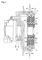
- Figure 1 is a partial sectional view of the swivel joint
- Figure 2 is a perspective view, partially in section, of the swivel joint
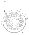
- Figure 3 is a sectional view taken along the line A-A in Figure 1
- Figure 4 is a sectional view taken along the line B-B in Figure 1
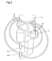
- Figure 5 is a perspective view of a state where hoses 2 and 3 are connected to a working device
- Figure 6 illustrates a diameter change of the hose.
- the swivel joint includes a rotating section 1 connected rotatably together with a rotating shaft W1 that constitutes a wrist section W of an industrial robot, a plurality of hoses 2 and 3 loosely spirally wound with a margin around an outer periphery of the rotating section 1, a plurality of bulkheads 4 that can house the plurality of hoses 2 and 3 in multiple stages, and a fixed wall 5 that non-rotatably fixes one end of each of the hoses 2 and 3 in outer peripheral portions of the bulkheads 4.
- the swivel joint may include electric power supply means including a disk-shaped slip ring and a brush so as to supply electric power from the robot body side to a working device, between a fixed section W2 that constitutes the wrist section W and the rotating section 1.
- a working device such as a robot hand or a welding gun is mounted to a tip of the rotating section 1.
- Rotation of the rotating section 1 (rotation of the rotating shaft W1 of the wrist section W) in Embodiment 1 includes a concept of forward/reverse rotation and pivot.
- the hoses 2 and 3 include two types of hoses: three fluid supply hoses 2 that supply a fluid such as a coolant (for example, water) or working oil from the robot body side to the working device side, and three fluid return hoses 3 that return the coolant or drain oil heated by the working device from the working device side to the robot body side.
- the hoses 2 and 3 may be tubes made of flexible members such as resin, rubber, or metal tubes, through which a fluid flows.
- the bulkheads 4 include seven doughnut-shaped metal plates, and mounted at spaced intervals around the rotating section 1 to form six annular spaces, which house the hoses 2 and 3. Each annular space has such a space that allows a diameter change or movement of the hoses 2 and 3 with rotation of the rotating section 1 with the hoses being loosely spirally wound. As shown in Figure 1 , the bulkhead 4 is fixed to the rotating section 1 by fastening means such as a screw on an inner peripheral side thereof, and is thus rotatable together with the rotating section 1.
- notch grooves 6 are provided in an inner peripheral portion of each bulkhead 4 at 180° intervals, and the other end of each of the hoses 2 and 3 wound around the rotating section 1 is led through the notch grooves 6 to the working device connected to a downstream side of the rotating section 1.
- the fixed wall 5 is a metal member formed to cover a half of outer peripheries of the plurality of bulkheads 4, and is fixed to the fixed section W2 that constitutes the wrist section W non-rotatably with respect to the rotating section 1.
- a total of six L-shaped pipe joints 7, three in one set, are mounted to the fixed wall 5 at 180° intervals, and one end of each of the hoses 2 and 3 extended from the robot body side are wound around the rotating section 1 via the L-shaped pipe joints 7.
- the hoses 2 and 3 can be easily introduced from the opening into the annular spaces formed by the bulkheads 4, and easily spirally wound around the rotating section 1 through the opening. Specifically, mounting and replacement of the hoses 2 and 3 are easily performed.
- the three fluid supply hoses 2 and the three return hoses 3 each brought together in one bundle are extended from the robot body side through an arm to the wrist section W, clamped once near the wrist section W, and then divided so that the supply hoses 2 are extended toward the L-shaped pipe joints 7 on the fixed wall 5 on one side (left side in Figure 1 ) and the return hoses 3 are extended toward the L-shaped pipe joints 7 on the fixed wall 5 on the other side (right side in Figure 1 ).
- the hoses 2 and 3 are turned so as to be fixed in the L-shaped pipe joints 7 and be substantially parallel to the bulkheads 4, and introduced into the annular spaces formed by the bulkheads 4.
- the supply hoses 2 and the return hoses 3 are alternately housed in the annular spaces in the multiple stages.
- each of the fluid supply hoses 2 fixed on the introducing side into the annular space is loosely spirally wound clockwise around the rotating section 1, and then extended through one notch groove 7 (notch groove on the right side in Figure 3 ) provided in the inner peripheral portion of the bulkhead 4 to the working device connected to the downstream side of the, rotating section 1.
- each of the return hoses 3 fixed on the introducing side into the annular space is loosely spirally wound counterclockwise around the rotating section 1, and then extended through the other notch groove 7 (notch groove on the left side in Figure 4 ) provided in the inner peripheral portion of the bulkhead 4 to the working device connected to the downstream side of the rotating section 1.
- the three fluid supply hoses 2 and the three return hoses 3 are connected to a transformer T, an upper chip C1, and a lower chip C2 that constitute the working device, and form a circulation path that supplies a coolant or the like from the robot body side to these members that constitute the working device, and further returns the fluid from the working device side to the robot body side.
- the hoses 2 and 3 can address rotation of ⁇ 360° or more according to the length of winding or the manner of winding (loose or firm winding) around the rotating section 1.
- the return hose 3 is wound around the rotating section 1 in the direction opposite to that of the supply hose 2 (counterclockwise), thus when the supply hose 2 rotates in the "tightened” direction, the return hose 3 is loosened so as to be expanded from the central side by the rotating shaft, and when the supply hose 2 rotates in the "loosened” direction, the return hose 3 is tightened so as to be wound toward the central side by the rotating shaft.
- the diameter of the spiral of each of the hoses 2 and 3 changes with rotation of the rotating section 1, and thus the hoses are not twisted or do not entangle, thereby allowing smooth wiring of the hoses 2 and 3 from the wrist side to the working device side or from the working device side to the wrist side.
- the swivel joint includes the hoses 2 and 3, the bulkheads 4, the fixed wall 5, and the L-shaped pipe joints 7, and each of the components can be relatively easily machined and produced at low cost.
- the fluid flows through the hose, and a slide surface of the hose (outer peripheral surface of the hose) does not directly come into contact with the fluid with rotation of the rotating section 1, and thus the hose is not influenced by impurity or the like in the fluid, if any, allowing an increase in life.
- the hose is merely spirally wound around the rotating section 1, the structure is simple, and replacement of the hose can be easily performed without removing the working device from the swivel joint or taking the swivel joint itself apart.
- a removable protective cover that covers the opening of the fixed wall 5 may be provided. This can prevent damage to the hoses 2 and 3 due to spatter (molten iron particles flying during welding) generated during working with a working device such as a welding gun.
- grease lubricant
- wax may be applied to each of the bulkheads 4 and the hoses 2 and 3 to allow a smooth diameter change and slide of the hoses 2 and 3 in the annular spaces during rotation. This prevents damage or degradation of the hoses due to friction and increases service life.
- each of the hoses 2 and 3 is inserted into the notch groove 6 in the bulkhead 4 so that the hoses 2 and 3 are rotatable together with the rotating section 1.
- a hollow section inside the rotating section 1 and a hole that provides communication between an outer peripheral wall of the rotating section 1 and the hollow section may be provided so as to introduce the hoses 2 and 3 to the inside of the rotating section 1.
Landscapes
- Engineering & Computer Science (AREA)
- Mechanical Engineering (AREA)
- Robotics (AREA)
- General Engineering & Computer Science (AREA)
- Joints Allowing Movement (AREA)
- Manipulator (AREA)
Abstract
characterized in that said fluid transmission path is a hose, and between said wrist section and said working device, the hose is loosely spirally wound with a margin around a shaft section that rotates together with said wrist section, and one end of said hose is non-rotatably fixed to the shaft section, and the other end is fixed so as to be movable with movement of said shaft section.
Description
- The present invention relates to a swivel joint that is placed between a forwardly/reversely rotatable wrist section provided on a robot body of an industrial robot and a working device side such as a welding gun or a hand mounted to a tip of the wrist section, and easily transmits a fluid such as a coolant (for example, water) or working oil from the wrist section side to the working device side.
- As a conventional swivel joint, there is a swivel joint 30 shown in
Figures 1 and2 in Japanese Patent Laid-Open No.10-332065 - Specifically, the drain oil from the actuator flows through a body section 331a of the outer cylinder oil passage 331 into an outer annular groove 331c, then flows through a communication hole 321c in the middle cylinder oil passage 321 into an inner annular groove 321d, further flows through a communication hole 311c into a body section 311a of the inner cylinder oil passage 311, and finally fed to the tank through a drain oil passage connected to a connecting portion 311b.
- In the inner annular groove 321d and the outer annular groove 331c, annular packings (O-rings) 34 and 35 are provided having slide surfaces on an outer peripheral surface of the inner cylinder or an outer peripheral surface of the middle cylinder to prevent communication between the annular grooves and leakage of the drain oil.
- However, the drain oil flowing through the annular grooves directly comes into contact with the slide surfaces and the annular packings, and dust, impurity, or abrasive powder in the oil bites into the slide surfaces or wear of the packings is accelerated, thereby reducing life of the swivel joint itself.
- Also, in the conventional swivel joint, the swivel joint and the working device are connected by fastening flanges thereof by a bolt, and when the packing or the like is damaged and needs replacement, it is necessary that the bolt is removed to remove the working device and then remove the swivel joint itself, and further the swivel joint is taken apart for replacement of a component such as the packing, which takes much labor.
- The present invention has an object to provide a swivel joint in which a fluid transmission path of such as a coolant, working oil, or drain oil is not influenced by dust or impurity in the fluid, a high sealing property is maintained, and replacement can be easily performed from outside when needed.
- To achieve the above-described object, the present invention provides a swivel joint that is placed between a working device and a forwardly/reversely rotatable wrist section provided on a body section of an industrial robot and includes a fluid transmission path for interconnecting the wrist section side and the working device side, characterized in that the fluid transmission path is a hose, and between the wrist section and the working device, the hose is loosely spirally wound with a margin around a shaft section that rotates together with the wrist section, and one end of the hose is non-rotatably fixed to the shaft section, and the other end is fixed so as to be movable with movement of the shaft section.
- In the swivel joint, the hose may include a fluid supply hose that supplies a fluid from the wrist section side to the working device side, and a fluid return hose that returns the fluid from the working device side to the wrist section side.
- In either of the swivel joints, the hose may be supported by a bulkhead mounted rotatably together with the shaft section.
- As described above, the swivel joint of the present invention includes the fluid transmission path for a coolant, working oil, or drain oil is constituted by the hose, and thus has a high sealing property. Also, the fluid flowing through the hose does not directly come into contact with a rotating shaft or the like, and can smoothly flow through the hose without being influenced by dust or impurity in the fluid, and replacement of the hose can be easily performed from outside when needed.
-
-
Figure 1 is a partial sectional view of a swivel joint of the present invention; -
Figure 2 is a perspective view, partially in section, of the swivel joint of the present invention; -
Figure 3 is a sectional view taken along the line A-A inFigure 1 ; -
Figure 4 is a sectional view taken along the line B-B inFigure 1 ; -
Figure 5 is a perspective view of a state where a hose is connected to a working device; and -
Figure 6 illustrates a diameter change of the hose. -
- 1
- rotating section
- 2
- fluid supply hose
- 3
- fluid return hose
- 4
- bulkhead
- 5
- fixed wall
- 6
- notch groove
- 7
- L-shaped pipe joint
- Now, embodiments as the best mode for carrying out a swivel joint of the present invention will be described with reference to the drawings.
-
Figure 1 is a partial sectional view of the swivel joint,Figure 2 is a perspective view, partially in section, of the swivel joint,Figure 3 is a sectional view taken along the line A-A inFigure 1 ,Figure 4 is a sectional view taken along the line B-B inFigure 1 ,Figure 5 is a perspective view of a state wherehoses Figure 6 illustrates a diameter change of the hose. - As shown in
Figures 1 and2 , the swivel joint includes a rotatingsection 1 connected rotatably together with a rotating shaft W1 that constitutes a wrist section W of an industrial robot, a plurality ofhoses section 1, a plurality ofbulkheads 4 that can house the plurality ofhoses fixed wall 5 that non-rotatably fixes one end of each of thehoses bulkheads 4. - Although not shown, the swivel joint may include electric power supply means including a disk-shaped slip ring and a brush so as to supply electric power from the robot body side to a working device, between a fixed section W2 that constitutes the wrist section W and the rotating
section 1. - As shown in
Figure 5 , a working device such as a robot hand or a welding gun is mounted to a tip of the rotatingsection 1. - Rotation of the rotating section 1 (rotation of the rotating shaft W1 of the wrist section W) in
Embodiment 1 includes a concept of forward/reverse rotation and pivot. - As shown in
Figures 1 and2 , thehoses fluid supply hoses 2 that supply a fluid such as a coolant (for example, water) or working oil from the robot body side to the working device side, and threefluid return hoses 3 that return the coolant or drain oil heated by the working device from the working device side to the robot body side. Thehoses - The
bulkheads 4 include seven doughnut-shaped metal plates, and mounted at spaced intervals around the rotatingsection 1 to form six annular spaces, which house thehoses hoses section 1 with the hoses being loosely spirally wound. As shown inFigure 1 , thebulkhead 4 is fixed to the rotatingsection 1 by fastening means such as a screw on an inner peripheral side thereof, and is thus rotatable together with the rotatingsection 1. Further, twonotch grooves 6 are provided in an inner peripheral portion of eachbulkhead 4 at 180° intervals, and the other end of each of thehoses section 1 is led through thenotch grooves 6 to the working device connected to a downstream side of the rotatingsection 1. - The
fixed wall 5 is a metal member formed to cover a half of outer peripheries of the plurality ofbulkheads 4, and is fixed to the fixed section W2 that constitutes the wrist section W non-rotatably with respect to the rotatingsection 1. A total of six L-shaped pipe joints 7, three in one set, are mounted to thefixed wall 5 at 180° intervals, and one end of each of thehoses section 1 via the L-shaped pipe joints 7. At this time, since thefixed wall 5 is formed to cover only the half of the outer peripheries of the bulkheads 4 (a section without thefixed wall 5 forms an opening), thehoses bulkheads 4, and easily spirally wound around the rotatingsection 1 through the opening. Specifically, mounting and replacement of thehoses - As shown in
Figure 1 , the threefluid supply hoses 2 and the threereturn hoses 3 each brought together in one bundle are extended from the robot body side through an arm to the wrist section W, clamped once near the wrist section W, and then divided so that thesupply hoses 2 are extended toward the L-shaped pipe joints 7 on thefixed wall 5 on one side (left side inFigure 1 ) and thereturn hoses 3 are extended toward the L-shaped pipe joints 7 on thefixed wall 5 on the other side (right side inFigure 1 ). Then, thehoses shaped pipe joints 7 and be substantially parallel to thebulkheads 4, and introduced into the annular spaces formed by thebulkheads 4. Thesupply hoses 2 and thereturn hoses 3 are alternately housed in the annular spaces in the multiple stages. - As shown in
Figure 3 , each of thefluid supply hoses 2 fixed on the introducing side into the annular space is loosely spirally wound clockwise around the rotatingsection 1, and then extended through one notch groove 7 (notch groove on the right side inFigure 3 ) provided in the inner peripheral portion of thebulkhead 4 to the working device connected to the downstream side of the, rotatingsection 1. - On the other hand, as shown in
Figure 4 , each of thereturn hoses 3 fixed on the introducing side into the annular space is loosely spirally wound counterclockwise around therotating section 1, and then extended through the other notch groove 7 (notch groove on the left side inFigure 4 ) provided in the inner peripheral portion of thebulkhead 4 to the working device connected to the downstream side of the rotatingsection 1. - Finally, in this embodiment, as shown in
Figure 5 , the threefluid supply hoses 2 and the threereturn hoses 3 are connected to a transformer T, an upper chip C1, and a lower chip C2 that constitute the working device, and form a circulation path that supplies a coolant or the like from the robot body side to these members that constitute the working device, and further returns the fluid from the working device side to the robot body side. - The
hoses section 1. - As shown in
Figure 6(a) , when therotating section 1 of the swivel joint starts rotating clockwise, thebulkhead 4 fixed rotatably together with therotating section 1 simultaneously starts rotating, and thus thesupply hose 2 fixed on one side to the L-shaped pipe joint 7 on the fixedwall 5 and inserted on the other side into thenotch groove 6 in thebulkhead 4 is moved with the rotation of therotating section 1, and winding of thesupply hose 2 is tightened so that the diameter of the loose spiral around therotating section 1 is reduced. - On the other hand, as shown in
Figure 6(b) , when therotating section 1 of the swivel joint starts rotating counterclockwise, thehose 2 tightly wound around therotating section 1 is moved with the rotation of therotating section 1, and winding of thesupply hose 2 is loosened so that the diameter of the spiral is increased. - The
return hose 3 is wound around therotating section 1 in the direction opposite to that of the supply hose 2 (counterclockwise), thus when thesupply hose 2 rotates in the "tightened" direction, thereturn hose 3 is loosened so as to be expanded from the central side by the rotating shaft, and when thesupply hose 2 rotates in the "loosened" direction, thereturn hose 3 is tightened so as to be wound toward the central side by the rotating shaft. - In this swivel joint, the diameter of the spiral of each of the
hoses rotating section 1, and thus the hoses are not twisted or do not entangle, thereby allowing smooth wiring of thehoses - The swivel joint includes the
hoses bulkheads 4, the fixedwall 5, and the L-shapedpipe joints 7, and each of the components can be relatively easily machined and produced at low cost. - Further, the fluid flows through the hose, and a slide surface of the hose (outer peripheral surface of the hose) does not directly come into contact with the fluid with rotation of the
rotating section 1, and thus the hose is not influenced by impurity or the like in the fluid, if any, allowing an increase in life. - Further, since the hose is merely spirally wound around the
rotating section 1, the structure is simple, and replacement of the hose can be easily performed without removing the working device from the swivel joint or taking the swivel joint itself apart. - A removable protective cover that covers the opening of the fixed
wall 5 may be provided. This can prevent damage to thehoses - Also, grease (lubricant) or wax may be applied to each of the
bulkheads 4 and thehoses hoses - Further, in the above-described embodiment, one end of each of the
hoses notch groove 6 in thebulkhead 4 so that thehoses rotating section 1. However, not limited to this, as long as the hoses can follow the rotation of therotating section 1, a hollow section inside therotating section 1 and a hole that provides communication between an outer peripheral wall of therotating section 1 and the hollow section may be provided so as to introduce thehoses rotating section 1.
Claims (3)
- A swivel joint that is placed between a working device and a forwardly/reversely rotatable wrist section provided on a body section of an industrial robot and includes a fluid transmission path for interconnecting the wrist section side and the working device side,
characterized in that said fluid transmission path is a hose, and between said wrist section and said working device, the hose is loosely spirally wound with a margin around a shaft section that rotates together with said wrist section, and one end of said hose is non-rotatably fixed to the shaft section, and the other end is fixed so as to be movable with movement of said shaft section. - The swivel joint according to claim 1, characterized in that said hose includes a fluid supply hose that supplies a fluid from the wrist section side to the working device side, and a fluid return hose that returns the fluid from the working device side to the wrist section side.
- The swivel joint according to claim 1 or 2, characterized in that said hose is supported by a bulkhead mounted rotatably together with said shaft section.
Applications Claiming Priority (2)
| Application Number | Priority Date | Filing Date | Title |
|---|---|---|---|
| JP2007129464A JP4432089B2 (en) | 2007-05-15 | 2007-05-15 | Swivel joint |
| PCT/JP2008/058803 WO2008143073A1 (en) | 2007-05-15 | 2008-05-14 | Swivel joint |
Publications (3)
| Publication Number | Publication Date |
|---|---|
| EP2149434A1 true EP2149434A1 (en) | 2010-02-03 |
| EP2149434A4 EP2149434A4 (en) | 2011-06-22 |
| EP2149434B1 EP2149434B1 (en) | 2012-08-15 |
Family
ID=40031782
Family Applications (1)
| Application Number | Title | Priority Date | Filing Date |
|---|---|---|---|
| EP08752674A Not-in-force EP2149434B1 (en) | 2007-05-15 | 2008-05-14 | Swivel joint |
Country Status (12)
| Country | Link |
|---|---|
| US (1) | US8454258B2 (en) |
| EP (1) | EP2149434B1 (en) |
| JP (1) | JP4432089B2 (en) |
| KR (1) | KR101409650B1 (en) |
| CN (1) | CN101687323B (en) |
| AU (1) | AU2008252085B2 (en) |
| BR (1) | BRPI0810279B1 (en) |
| CA (1) | CA2686841C (en) |
| ES (1) | ES2392700T3 (en) |
| MX (1) | MX2009011775A (en) |
| RU (1) | RU2463157C2 (en) |
| WO (1) | WO2008143073A1 (en) |
Cited By (3)
| Publication number | Priority date | Publication date | Assignee | Title |
|---|---|---|---|---|
| US9562547B2 (en) | 2014-08-29 | 2017-02-07 | Abb Schweiz Ag | Electric hydraulic actuator |
| US9682473B2 (en) | 2014-08-29 | 2017-06-20 | Abb Schweiz Ag | Electric fluidic rotary joint actuator with pump |
| EP4549100A1 (en) * | 2023-10-31 | 2025-05-07 | Martini, Walter | Articulated robot for handling workpieces |
Families Citing this family (9)
| Publication number | Priority date | Publication date | Assignee | Title |
|---|---|---|---|---|
| DE102008001314A1 (en) * | 2008-04-22 | 2009-10-29 | Robert Bosch Gmbh | Device for moving and positioning an object in space |
| JP2011078227A (en) * | 2009-09-30 | 2011-04-14 | Nitta Corp | Power relay swivel joint |
| JP5538017B2 (en) * | 2010-03-25 | 2014-07-02 | ニッタ株式会社 | Swivel joint |
| WO2015141196A1 (en) * | 2014-03-17 | 2015-09-24 | パナソニックIpマネジメント株式会社 | Laser machining robot |
| DE102017203741A1 (en) * | 2017-03-07 | 2018-09-13 | Kuka Deutschland Gmbh | Robotic arm with a mechanical stop device |
| US10836052B2 (en) * | 2019-02-06 | 2020-11-17 | Hiwin Technologies Corp. | Connection module using in robot |
| AT522542B1 (en) * | 2019-05-09 | 2022-07-15 | Facc Ag | Interchangeable coupling, changing device and testing and processing system |
| IT201900012294A1 (en) * | 2019-07-18 | 2021-01-18 | Restart S R L | POWER SUPPLY SYSTEM |
| DE102022121226A1 (en) | 2022-08-23 | 2024-02-29 | Rsp Gmbh | Material pickup device for a suction excavator and suction excavator with this material pickup device |
Family Cites Families (15)
| Publication number | Priority date | Publication date | Assignee | Title |
|---|---|---|---|---|
| FR2413603A1 (en) * | 1977-12-30 | 1979-07-27 | Emh | ROTATING JOINT DEVICE WITH MULTIPLE PIPING PASSAGE, ESPECIALLY FOR LOADING OR TRANSFER COLUMNS IN MARINE SITE |
| US5101681A (en) * | 1987-06-09 | 1992-04-07 | Ameus Corporation | Interlocking-body connective joints |
| JPH03256691A (en) * | 1990-03-08 | 1991-11-15 | Fanuc Ltd | Cable processing structure for revolving shaft for industrial robot |
| JP2931701B2 (en) | 1991-07-05 | 1999-08-09 | 株式会社東芝 | Clamp circuit |
| JPH0514767U (en) * | 1991-08-08 | 1993-02-26 | トヨタ車体株式会社 | Installation structure of long elastic body |
| US5777267A (en) * | 1996-06-28 | 1998-07-07 | Abb Flexible Automation, Inc. | Harness assembly to provide signals to end effector |
| JPH10332065A (en) | 1997-05-29 | 1998-12-15 | Aichi Corp | Swivel joint |
| JP4096348B2 (en) * | 2000-04-07 | 2008-06-04 | 株式会社安川電機 | Cable processing equipment |
| JP2002307370A (en) * | 2001-04-17 | 2002-10-23 | Kondo Seisakusho:Kk | Rotary joint |
| CN2572180Y (en) * | 2002-10-18 | 2003-09-10 | 上海大学 | Gas-electricity mixing transmission rotary joint |
| JP4250039B2 (en) * | 2003-08-22 | 2009-04-08 | 株式会社小松製作所 | Lock pin insertion detection device for crawler vehicle |
| CA2546777C (en) | 2003-12-02 | 2012-07-10 | Robert Bosch Gmbh | Rotary leadthrough of a robot arm |
| JP4433166B2 (en) | 2004-02-20 | 2010-03-17 | 株式会社安川電機 | Manipulator device |
| JP4286684B2 (en) * | 2004-02-27 | 2009-07-01 | 株式会社ダイヘン | Cable arrangement structure for arc welding robot |
| US7559590B1 (en) * | 2005-10-19 | 2009-07-14 | Western Digital Technologies, Inc. | Pressure transmission assembly for mounting to a robotic device having a rotatable end effector |
-
2007
- 2007-05-15 JP JP2007129464A patent/JP4432089B2/en active Active
-
2008
- 2008-05-14 RU RU2009141860/02A patent/RU2463157C2/en active
- 2008-05-14 BR BRPI0810279A patent/BRPI0810279B1/en not_active IP Right Cessation
- 2008-05-14 CA CA2686841A patent/CA2686841C/en not_active Expired - Fee Related
- 2008-05-14 EP EP08752674A patent/EP2149434B1/en not_active Not-in-force
- 2008-05-14 WO PCT/JP2008/058803 patent/WO2008143073A1/en not_active Ceased
- 2008-05-14 ES ES08752674T patent/ES2392700T3/en active Active
- 2008-05-14 KR KR1020097022195A patent/KR101409650B1/en not_active Expired - Fee Related
- 2008-05-14 AU AU2008252085A patent/AU2008252085B2/en not_active Ceased
- 2008-05-14 CN CN200880015082XA patent/CN101687323B/en not_active Expired - Fee Related
- 2008-05-14 US US12/451,446 patent/US8454258B2/en active Active
- 2008-05-14 MX MX2009011775A patent/MX2009011775A/en active IP Right Grant
Cited By (3)
| Publication number | Priority date | Publication date | Assignee | Title |
|---|---|---|---|---|
| US9562547B2 (en) | 2014-08-29 | 2017-02-07 | Abb Schweiz Ag | Electric hydraulic actuator |
| US9682473B2 (en) | 2014-08-29 | 2017-06-20 | Abb Schweiz Ag | Electric fluidic rotary joint actuator with pump |
| EP4549100A1 (en) * | 2023-10-31 | 2025-05-07 | Martini, Walter | Articulated robot for handling workpieces |
Also Published As
| Publication number | Publication date |
|---|---|
| WO2008143073A1 (en) | 2008-11-27 |
| MX2009011775A (en) | 2010-02-11 |
| BRPI0810279B1 (en) | 2019-12-17 |
| KR20100015844A (en) | 2010-02-12 |
| KR101409650B1 (en) | 2014-06-18 |
| AU2008252085A1 (en) | 2008-11-27 |
| ES2392700T3 (en) | 2012-12-13 |
| JP2008284621A (en) | 2008-11-27 |
| BRPI0810279A2 (en) | 2014-12-30 |
| CN101687323B (en) | 2011-12-14 |
| EP2149434A4 (en) | 2011-06-22 |
| CA2686841C (en) | 2014-12-30 |
| US8454258B2 (en) | 2013-06-04 |
| EP2149434B1 (en) | 2012-08-15 |
| RU2463157C2 (en) | 2012-10-10 |
| US20100101358A1 (en) | 2010-04-29 |
| JP4432089B2 (en) | 2010-03-17 |
| AU2008252085B2 (en) | 2014-05-29 |
| CN101687323A (en) | 2010-03-31 |
| RU2009141860A (en) | 2011-06-20 |
| CA2686841A1 (en) | 2008-11-27 |
Similar Documents
| Publication | Publication Date | Title |
|---|---|---|
| CA2686841C (en) | Swivel joint | |
| KR100711314B1 (en) | Multijoint manipulator | |
| JP4511738B2 (en) | Tube coupling | |
| KR100217555B1 (en) | Wrist device for industrial robot | |
| JP4981540B2 (en) | Equipment connection structure for existing fluid pipes and undisturbed fluid equipment installation method | |
| EA034560B1 (en) | Device for coating a pipe or a portion of pipe | |
| US20050034552A1 (en) | Industrial robot | |
| US5219187A (en) | Pipe connection | |
| WO2015131288A1 (en) | Cable management system and devices | |
| TW202319201A (en) | Wire body fixing structure, machine, robot, and actuator | |
| JP2002079487A (en) | Industrial robot wrist device | |
| JP4559419B2 (en) | Robot wrist | |
| US7806638B1 (en) | Insulated air tube for a reinstatement cutting machine | |
| JPH0724777A (en) | Robot arm structure equipped with piping and wiring | |
| JP7364775B2 (en) | A robot equipped with a drive unit structure and joints that rotate multiple structures relatively | |
| KR102053686B1 (en) | Articulated robot having structures that isolate occurrence of foreign material | |
| JP4287965B2 (en) | Valve mounting device for fluid transport pipe | |
| CN223339474U (en) | Six-degree-of-freedom spraying robot wiring structure | |
| US20030067161A1 (en) | Hydraulic swivel connector | |
| EP0190360B2 (en) | Industrial robot having hollow arm structure | |
| JPS6133887A (en) | Hollow arm structure of industrial robot | |
| EP4549100A1 (en) | Articulated robot for handling workpieces | |
| WO2018069161A1 (en) | Wire feed mechanism for weld torch | |
| JP2005180565A (en) | Swivel joint | |
| JPS59196189A (en) | Assembly of wrist of multispindle robot |
Legal Events
| Date | Code | Title | Description |
|---|---|---|---|
| PUAI | Public reference made under article 153(3) epc to a published international application that has entered the european phase |
Free format text: ORIGINAL CODE: 0009012 |
|
| 17P | Request for examination filed |
Effective date: 20091113 |
|
| AK | Designated contracting states |
Kind code of ref document: A1 Designated state(s): AT BE BG CH CY CZ DE DK EE ES FI FR GB GR HR HU IE IS IT LI LT LU LV MC MT NL NO PL PT RO SE SI SK TR |
|
| AX | Request for extension of the european patent |
Extension state: AL BA MK RS |
|
| DAX | Request for extension of the european patent (deleted) | ||
| A4 | Supplementary search report drawn up and despatched |
Effective date: 20110525 |
|
| GRAP | Despatch of communication of intention to grant a patent |
Free format text: ORIGINAL CODE: EPIDOSNIGR1 |
|
| GRAC | Information related to communication of intention to grant a patent modified |
Free format text: ORIGINAL CODE: EPIDOSCIGR1 |
|
| GRAS | Grant fee paid |
Free format text: ORIGINAL CODE: EPIDOSNIGR3 |
|
| GRAA | (expected) grant |
Free format text: ORIGINAL CODE: 0009210 |
|
| AK | Designated contracting states |
Kind code of ref document: B1 Designated state(s): AT BE BG CH CY CZ DE DK EE ES FI FR GB GR HR HU IE IS IT LI LT LU LV MC MT NL NO PL PT RO SE SI SK TR |
|
| REG | Reference to a national code |
Ref country code: CH Ref legal event code: EP Ref country code: AT Ref legal event code: REF Ref document number: 570564 Country of ref document: AT Kind code of ref document: T Effective date: 20120815 Ref country code: GB Ref legal event code: FG4D |
|
| REG | Reference to a national code |
Ref country code: IE Ref legal event code: FG4D |
|
| REG | Reference to a national code |
Ref country code: DE Ref legal event code: R096 Ref document number: 602008018039 Country of ref document: DE Effective date: 20121011 |
|
| REG | Reference to a national code |
Ref country code: ES Ref legal event code: FG2A Ref document number: 2392700 Country of ref document: ES Kind code of ref document: T3 Effective date: 20121213 |
|
| REG | Reference to a national code |
Ref country code: NL Ref legal event code: VDEP Effective date: 20120815 |
|
| REG | Reference to a national code |
Ref country code: AT Ref legal event code: MK05 Ref document number: 570564 Country of ref document: AT Kind code of ref document: T Effective date: 20120815 |
|
| PG25 | Lapsed in a contracting state [announced via postgrant information from national office to epo] |
Ref country code: IS Free format text: LAPSE BECAUSE OF FAILURE TO SUBMIT A TRANSLATION OF THE DESCRIPTION OR TO PAY THE FEE WITHIN THE PRESCRIBED TIME-LIMIT Effective date: 20121215 Ref country code: HR Free format text: LAPSE BECAUSE OF FAILURE TO SUBMIT A TRANSLATION OF THE DESCRIPTION OR TO PAY THE FEE WITHIN THE PRESCRIBED TIME-LIMIT Effective date: 20120815 Ref country code: CY Free format text: LAPSE BECAUSE OF FAILURE TO SUBMIT A TRANSLATION OF THE DESCRIPTION OR TO PAY THE FEE WITHIN THE PRESCRIBED TIME-LIMIT Effective date: 20120815 Ref country code: AT Free format text: LAPSE BECAUSE OF FAILURE TO SUBMIT A TRANSLATION OF THE DESCRIPTION OR TO PAY THE FEE WITHIN THE PRESCRIBED TIME-LIMIT Effective date: 20120815 Ref country code: LT Free format text: LAPSE BECAUSE OF FAILURE TO SUBMIT A TRANSLATION OF THE DESCRIPTION OR TO PAY THE FEE WITHIN THE PRESCRIBED TIME-LIMIT Effective date: 20120815 Ref country code: FI Free format text: LAPSE BECAUSE OF FAILURE TO SUBMIT A TRANSLATION OF THE DESCRIPTION OR TO PAY THE FEE WITHIN THE PRESCRIBED TIME-LIMIT Effective date: 20120815 Ref country code: NO Free format text: LAPSE BECAUSE OF FAILURE TO SUBMIT A TRANSLATION OF THE DESCRIPTION OR TO PAY THE FEE WITHIN THE PRESCRIBED TIME-LIMIT Effective date: 20121115 |
|
| RAP2 | Party data changed (patent owner data changed or rights of a patent transferred) |
Owner name: TOYOTA JIDOSHA KABUSHIKI KAISHA Owner name: NITTA CORPORATION |
|
| PG25 | Lapsed in a contracting state [announced via postgrant information from national office to epo] |
Ref country code: BE Free format text: LAPSE BECAUSE OF FAILURE TO SUBMIT A TRANSLATION OF THE DESCRIPTION OR TO PAY THE FEE WITHIN THE PRESCRIBED TIME-LIMIT Effective date: 20120815 Ref country code: SI Free format text: LAPSE BECAUSE OF FAILURE TO SUBMIT A TRANSLATION OF THE DESCRIPTION OR TO PAY THE FEE WITHIN THE PRESCRIBED TIME-LIMIT Effective date: 20120815 Ref country code: GR Free format text: LAPSE BECAUSE OF FAILURE TO SUBMIT A TRANSLATION OF THE DESCRIPTION OR TO PAY THE FEE WITHIN THE PRESCRIBED TIME-LIMIT Effective date: 20121116 Ref country code: SE Free format text: LAPSE BECAUSE OF FAILURE TO SUBMIT A TRANSLATION OF THE DESCRIPTION OR TO PAY THE FEE WITHIN THE PRESCRIBED TIME-LIMIT Effective date: 20120815 Ref country code: PT Free format text: LAPSE BECAUSE OF FAILURE TO SUBMIT A TRANSLATION OF THE DESCRIPTION OR TO PAY THE FEE WITHIN THE PRESCRIBED TIME-LIMIT Effective date: 20121217 Ref country code: LV Free format text: LAPSE BECAUSE OF FAILURE TO SUBMIT A TRANSLATION OF THE DESCRIPTION OR TO PAY THE FEE WITHIN THE PRESCRIBED TIME-LIMIT Effective date: 20120815 Ref country code: PL Free format text: LAPSE BECAUSE OF FAILURE TO SUBMIT A TRANSLATION OF THE DESCRIPTION OR TO PAY THE FEE WITHIN THE PRESCRIBED TIME-LIMIT Effective date: 20120815 |
|
| PG25 | Lapsed in a contracting state [announced via postgrant information from national office to epo] |
Ref country code: NL Free format text: LAPSE BECAUSE OF FAILURE TO SUBMIT A TRANSLATION OF THE DESCRIPTION OR TO PAY THE FEE WITHIN THE PRESCRIBED TIME-LIMIT Effective date: 20120815 |
|
| PG25 | Lapsed in a contracting state [announced via postgrant information from national office to epo] |
Ref country code: RO Free format text: LAPSE BECAUSE OF FAILURE TO SUBMIT A TRANSLATION OF THE DESCRIPTION OR TO PAY THE FEE WITHIN THE PRESCRIBED TIME-LIMIT Effective date: 20120815 Ref country code: EE Free format text: LAPSE BECAUSE OF FAILURE TO SUBMIT A TRANSLATION OF THE DESCRIPTION OR TO PAY THE FEE WITHIN THE PRESCRIBED TIME-LIMIT Effective date: 20120815 Ref country code: DK Free format text: LAPSE BECAUSE OF FAILURE TO SUBMIT A TRANSLATION OF THE DESCRIPTION OR TO PAY THE FEE WITHIN THE PRESCRIBED TIME-LIMIT Effective date: 20120815 |
|
| PG25 | Lapsed in a contracting state [announced via postgrant information from national office to epo] |
Ref country code: SK Free format text: LAPSE BECAUSE OF FAILURE TO SUBMIT A TRANSLATION OF THE DESCRIPTION OR TO PAY THE FEE WITHIN THE PRESCRIBED TIME-LIMIT Effective date: 20120815 |
|
| PLBE | No opposition filed within time limit |
Free format text: ORIGINAL CODE: 0009261 |
|
| STAA | Information on the status of an ep patent application or granted ep patent |
Free format text: STATUS: NO OPPOSITION FILED WITHIN TIME LIMIT |
|
| 26N | No opposition filed |
Effective date: 20130516 |
|
| PG25 | Lapsed in a contracting state [announced via postgrant information from national office to epo] |
Ref country code: BG Free format text: LAPSE BECAUSE OF FAILURE TO SUBMIT A TRANSLATION OF THE DESCRIPTION OR TO PAY THE FEE WITHIN THE PRESCRIBED TIME-LIMIT Effective date: 20121115 |
|
| REG | Reference to a national code |
Ref country code: DE Ref legal event code: R097 Ref document number: 602008018039 Country of ref document: DE Effective date: 20130516 |
|
| PG25 | Lapsed in a contracting state [announced via postgrant information from national office to epo] |
Ref country code: MC Free format text: LAPSE BECAUSE OF FAILURE TO SUBMIT A TRANSLATION OF THE DESCRIPTION OR TO PAY THE FEE WITHIN THE PRESCRIBED TIME-LIMIT Effective date: 20120815 |
|
| REG | Reference to a national code |
Ref country code: CH Ref legal event code: PL |
|
| PG25 | Lapsed in a contracting state [announced via postgrant information from national office to epo] |
Ref country code: CH Free format text: LAPSE BECAUSE OF NON-PAYMENT OF DUE FEES Effective date: 20130531 Ref country code: LI Free format text: LAPSE BECAUSE OF NON-PAYMENT OF DUE FEES Effective date: 20130531 |
|
| REG | Reference to a national code |
Ref country code: IE Ref legal event code: MM4A |
|
| PG25 | Lapsed in a contracting state [announced via postgrant information from national office to epo] |
Ref country code: IE Free format text: LAPSE BECAUSE OF NON-PAYMENT OF DUE FEES Effective date: 20130514 |
|
| PG25 | Lapsed in a contracting state [announced via postgrant information from national office to epo] |
Ref country code: MT Free format text: LAPSE BECAUSE OF FAILURE TO SUBMIT A TRANSLATION OF THE DESCRIPTION OR TO PAY THE FEE WITHIN THE PRESCRIBED TIME-LIMIT Effective date: 20120815 |
|
| PG25 | Lapsed in a contracting state [announced via postgrant information from national office to epo] |
Ref country code: LU Free format text: LAPSE BECAUSE OF NON-PAYMENT OF DUE FEES Effective date: 20130514 Ref country code: HU Free format text: LAPSE BECAUSE OF FAILURE TO SUBMIT A TRANSLATION OF THE DESCRIPTION OR TO PAY THE FEE WITHIN THE PRESCRIBED TIME-LIMIT; INVALID AB INITIO Effective date: 20080514 |
|
| REG | Reference to a national code |
Ref country code: FR Ref legal event code: PLFP Year of fee payment: 9 |
|
| REG | Reference to a national code |
Ref country code: DE Ref legal event code: R084 Ref document number: 602008018039 Country of ref document: DE |
|
| REG | Reference to a national code |
Ref country code: GB Ref legal event code: 746 Effective date: 20170110 |
|
| REG | Reference to a national code |
Ref country code: FR Ref legal event code: PLFP Year of fee payment: 10 |
|
| REG | Reference to a national code |
Ref country code: FR Ref legal event code: PLFP Year of fee payment: 11 |
|
| PGFP | Annual fee paid to national office [announced via postgrant information from national office to epo] |
Ref country code: FR Payment date: 20210525 Year of fee payment: 14 Ref country code: IT Payment date: 20210527 Year of fee payment: 14 Ref country code: CZ Payment date: 20210514 Year of fee payment: 14 Ref country code: DE Payment date: 20210520 Year of fee payment: 14 |
|
| PGFP | Annual fee paid to national office [announced via postgrant information from national office to epo] |
Ref country code: TR Payment date: 20210506 Year of fee payment: 14 Ref country code: GB Payment date: 20210520 Year of fee payment: 14 |
|
| PGFP | Annual fee paid to national office [announced via postgrant information from national office to epo] |
Ref country code: ES Payment date: 20210721 Year of fee payment: 14 |
|
| REG | Reference to a national code |
Ref country code: DE Ref legal event code: R119 Ref document number: 602008018039 Country of ref document: DE |
|
| GBPC | Gb: european patent ceased through non-payment of renewal fee |
Effective date: 20220514 |
|
| PG25 | Lapsed in a contracting state [announced via postgrant information from national office to epo] |
Ref country code: CZ Free format text: LAPSE BECAUSE OF NON-PAYMENT OF DUE FEES Effective date: 20220514 |
|
| PG25 | Lapsed in a contracting state [announced via postgrant information from national office to epo] |
Ref country code: FR Free format text: LAPSE BECAUSE OF NON-PAYMENT OF DUE FEES Effective date: 20220531 |
|
| PG25 | Lapsed in a contracting state [announced via postgrant information from national office to epo] |
Ref country code: GB Free format text: LAPSE BECAUSE OF NON-PAYMENT OF DUE FEES Effective date: 20220514 Ref country code: DE Free format text: LAPSE BECAUSE OF NON-PAYMENT OF DUE FEES Effective date: 20221201 |
|
| REG | Reference to a national code |
Ref country code: ES Ref legal event code: FD2A Effective date: 20230629 |
|
| PG25 | Lapsed in a contracting state [announced via postgrant information from national office to epo] |
Ref country code: IT Free format text: LAPSE BECAUSE OF NON-PAYMENT OF DUE FEES Effective date: 20220514 Ref country code: ES Free format text: LAPSE BECAUSE OF NON-PAYMENT OF DUE FEES Effective date: 20220515 |
|
| PG25 | Lapsed in a contracting state [announced via postgrant information from national office to epo] |
Ref country code: TR Free format text: LAPSE BECAUSE OF NON-PAYMENT OF DUE FEES Effective date: 20220514 |