EP2149048B1 - Device and process for binding assays - Google Patents
Device and process for binding assays Download PDFInfo
- Publication number
- EP2149048B1 EP2149048B1 EP08760265A EP08760265A EP2149048B1 EP 2149048 B1 EP2149048 B1 EP 2149048B1 EP 08760265 A EP08760265 A EP 08760265A EP 08760265 A EP08760265 A EP 08760265A EP 2149048 B1 EP2149048 B1 EP 2149048B1
- Authority
- EP
- European Patent Office
- Prior art keywords
- segments
- receptors
- porous filler
- analyte
- transmittance
- Prior art date
- Legal status (The legal status is an assumption and is not a legal conclusion. Google has not performed a legal analysis and makes no representation as to the accuracy of the status listed.)
- Not-in-force
Links
- 238000000034 method Methods 0.000 title claims description 21
- 230000008569 process Effects 0.000 title claims description 8
- 238000000159 protein binding assay Methods 0.000 title description 2
- 239000000463 material Substances 0.000 claims description 23
- 238000002834 transmittance Methods 0.000 claims description 22
- 239000000945 filler Substances 0.000 claims description 17
- 239000012491 analyte Substances 0.000 claims description 16
- 239000011148 porous material Substances 0.000 claims description 16
- 238000011156 evaluation Methods 0.000 claims description 14
- 238000005259 measurement Methods 0.000 claims description 13
- 238000012360 testing method Methods 0.000 claims description 12
- 238000011088 calibration curve Methods 0.000 claims description 9
- 239000002245 particle Substances 0.000 claims description 6
- 239000003153 chemical reaction reagent Substances 0.000 claims description 5
- 102000004190 Enzymes Human genes 0.000 claims description 4
- 108090000790 Enzymes Proteins 0.000 claims description 4
- 238000013461 design Methods 0.000 claims description 4
- 238000000149 argon plasma sintering Methods 0.000 claims description 3
- 238000010186 staining Methods 0.000 claims description 3
- 238000001179 sorption measurement Methods 0.000 claims description 2
- 239000000758 substrate Substances 0.000 claims description 2
- 230000003287 optical effect Effects 0.000 description 12
- 239000003446 ligand Substances 0.000 description 11
- 230000027455 binding Effects 0.000 description 8
- 239000000872 buffer Substances 0.000 description 8
- 241000589602 Francisella tularensis Species 0.000 description 7
- 238000001514 detection method Methods 0.000 description 7
- 238000011534 incubation Methods 0.000 description 7
- 238000003556 assay Methods 0.000 description 6
- 239000000243 solution Substances 0.000 description 6
- 239000002250 absorbent Substances 0.000 description 5
- 230000002745 absorbent Effects 0.000 description 5
- 229920001903 high density polyethylene Polymers 0.000 description 5
- 239000004700 high-density polyethylene Substances 0.000 description 5
- 230000001376 precipitating effect Effects 0.000 description 5
- 241000194019 Streptococcus mutans Species 0.000 description 4
- 241000607479 Yersinia pestis Species 0.000 description 4
- 238000004458 analytical method Methods 0.000 description 4
- 239000012528 membrane Substances 0.000 description 4
- 239000002158 endotoxin Substances 0.000 description 3
- 238000003780 insertion Methods 0.000 description 3
- 230000037431 insertion Effects 0.000 description 3
- 229920006008 lipopolysaccharide Polymers 0.000 description 3
- 238000002360 preparation method Methods 0.000 description 3
- 238000011002 quantification Methods 0.000 description 3
- 230000035945 sensitivity Effects 0.000 description 3
- 210000002966 serum Anatomy 0.000 description 3
- 241000894007 species Species 0.000 description 3
- 239000000020 Nitrocellulose Substances 0.000 description 2
- 241000283973 Oryctolagus cuniculus Species 0.000 description 2
- 102000003992 Peroxidases Human genes 0.000 description 2
- 101710084578 Short neurotoxin 1 Proteins 0.000 description 2
- 101710182532 Toxin a Proteins 0.000 description 2
- 239000003463 adsorbent Substances 0.000 description 2
- XAGFODPZIPBFFR-UHFFFAOYSA-N aluminium Chemical compound [Al] XAGFODPZIPBFFR-UHFFFAOYSA-N 0.000 description 2
- 229910052782 aluminium Inorganic materials 0.000 description 2
- 239000000427 antigen Substances 0.000 description 2
- 102000036639 antigens Human genes 0.000 description 2
- 108091007433 antigens Proteins 0.000 description 2
- 230000000712 assembly Effects 0.000 description 2
- 238000000429 assembly Methods 0.000 description 2
- 238000006243 chemical reaction Methods 0.000 description 2
- 239000011888 foil Substances 0.000 description 2
- 239000003365 glass fiber Substances 0.000 description 2
- 239000010931 gold Substances 0.000 description 2
- 229910052737 gold Inorganic materials 0.000 description 2
- -1 immuno Substances 0.000 description 2
- 238000003018 immunoassay Methods 0.000 description 2
- 230000000984 immunochemical effect Effects 0.000 description 2
- 238000002372 labelling Methods 0.000 description 2
- 239000007788 liquid Substances 0.000 description 2
- 239000006249 magnetic particle Substances 0.000 description 2
- 229920001220 nitrocellulos Polymers 0.000 description 2
- 108040007629 peroxidase activity proteins Proteins 0.000 description 2
- 238000005375 photometry Methods 0.000 description 2
- 230000009870 specific binding Effects 0.000 description 2
- 239000000126 substance Substances 0.000 description 2
- 238000010998 test method Methods 0.000 description 2
- UAIUNKRWKOVEES-UHFFFAOYSA-N 3,3',5,5'-tetramethylbenzidine Chemical compound CC1=C(N)C(C)=CC(C=2C=C(C)C(N)=C(C)C=2)=C1 UAIUNKRWKOVEES-UHFFFAOYSA-N 0.000 description 1
- YRNWIFYIFSBPAU-UHFFFAOYSA-N 4-[4-(dimethylamino)phenyl]-n,n-dimethylaniline Chemical compound C1=CC(N(C)C)=CC=C1C1=CC=C(N(C)C)C=C1 YRNWIFYIFSBPAU-UHFFFAOYSA-N 0.000 description 1
- 239000004698 Polyethylene Substances 0.000 description 1
- 230000009471 action Effects 0.000 description 1
- 238000001042 affinity chromatography Methods 0.000 description 1
- 238000003491 array Methods 0.000 description 1
- 230000008033 biological extinction Effects 0.000 description 1
- 230000005540 biological transmission Effects 0.000 description 1
- 230000015572 biosynthetic process Effects 0.000 description 1
- 229960002685 biotin Drugs 0.000 description 1
- 239000011616 biotin Substances 0.000 description 1
- 238000004061 bleaching Methods 0.000 description 1
- 210000001124 body fluid Anatomy 0.000 description 1
- 239000010839 body fluid Substances 0.000 description 1
- 239000007975 buffered saline Substances 0.000 description 1
- 238000004113 cell culture Methods 0.000 description 1
- 230000008859 change Effects 0.000 description 1
- 238000004440 column chromatography Methods 0.000 description 1
- 238000010276 construction Methods 0.000 description 1
- 230000001419 dependent effect Effects 0.000 description 1
- 238000011161 development Methods 0.000 description 1
- 238000010790 dilution Methods 0.000 description 1
- 239000012895 dilution Substances 0.000 description 1
- 230000000694 effects Effects 0.000 description 1
- 238000005516 engineering process Methods 0.000 description 1
- 238000000605 extraction Methods 0.000 description 1
- 239000012530 fluid Substances 0.000 description 1
- 238000005558 fluorometry Methods 0.000 description 1
- PCHJSUWPFVWCPO-UHFFFAOYSA-N gold Chemical compound [Au] PCHJSUWPFVWCPO-UHFFFAOYSA-N 0.000 description 1
- 230000002706 hydrostatic effect Effects 0.000 description 1
- 230000001900 immune effect Effects 0.000 description 1
- 229940127121 immunoconjugate Drugs 0.000 description 1
- 229940027941 immunoglobulin g Drugs 0.000 description 1
- 230000006872 improvement Effects 0.000 description 1
- 230000003993 interaction Effects 0.000 description 1
- 239000007791 liquid phase Substances 0.000 description 1
- 239000003550 marker Substances 0.000 description 1
- 238000007620 mathematical function Methods 0.000 description 1
- 238000007747 plating Methods 0.000 description 1
- 229920000573 polyethylene Polymers 0.000 description 1
- 239000002244 precipitate Substances 0.000 description 1
- 238000009597 pregnancy test Methods 0.000 description 1
- 239000000047 product Substances 0.000 description 1
- 238000010791 quenching Methods 0.000 description 1
- 230000000171 quenching effect Effects 0.000 description 1
- 239000011541 reaction mixture Substances 0.000 description 1
- 238000002310 reflectometry Methods 0.000 description 1
- 238000000926 separation method Methods 0.000 description 1
- 239000007787 solid Substances 0.000 description 1
- 230000000007 visual effect Effects 0.000 description 1
Images


Classifications
-
- G—PHYSICS
- G01—MEASURING; TESTING
- G01N—INVESTIGATING OR ANALYSING MATERIALS BY DETERMINING THEIR CHEMICAL OR PHYSICAL PROPERTIES
- G01N33/00—Investigating or analysing materials by specific methods not covered by groups G01N1/00 - G01N31/00
- G01N33/48—Biological material, e.g. blood, urine; Haemocytometers
- G01N33/50—Chemical analysis of biological material, e.g. blood, urine; Testing involving biospecific ligand binding methods; Immunological testing
- G01N33/53—Immunoassay; Biospecific binding assay; Materials therefor
- G01N33/543—Immunoassay; Biospecific binding assay; Materials therefor with an insoluble carrier for immobilising immunochemicals
- G01N33/54353—Immunoassay; Biospecific binding assay; Materials therefor with an insoluble carrier for immobilising immunochemicals with ligand attached to the carrier via a chemical coupling agent
-
- G—PHYSICS
- G01—MEASURING; TESTING
- G01N—INVESTIGATING OR ANALYSING MATERIALS BY DETERMINING THEIR CHEMICAL OR PHYSICAL PROPERTIES
- G01N21/00—Investigating or analysing materials by the use of optical means, i.e. using sub-millimetre waves, infrared, visible or ultraviolet light
- G01N21/75—Systems in which material is subjected to a chemical reaction, the progress or the result of the reaction being investigated
- G01N21/77—Systems in which material is subjected to a chemical reaction, the progress or the result of the reaction being investigated by observing the effect on a chemical indicator
- G01N21/78—Systems in which material is subjected to a chemical reaction, the progress or the result of the reaction being investigated by observing the effect on a chemical indicator producing a change of colour
Definitions
- the present invention relates to a process and a device for performing quantitative affinity-chromatographical quick tests with photometric evaluation with a porous filler material having a reflecting inner surface and receptors immobilized thereon and being provided in a container having an inlet and outlet.
- Affinity-chromatographical quick tests are based on biospecific interactions of ligands and receptors.
- the receptor is immobilized on a surface of a solid while the ligand to be assayed is supplied via a liquid phase and is specifically bound to the surface.
- a usual construction form for quick tests is described in U.S. Patent No. 4,943,522 .
- Such quick tests are employed, for example, as pregnancy test strips. They are prepared on the basis of nitrocellulose strips which are capped by a glass fiber membrane at the upper portion thereof. The sample is applied to the upper portion of the glass fiber membrane and reacts, while it migrates through the non-woven material, with the conjugate incorporated therein. As a rule, these are antibody-gold particles.
- the immunocomplex formed migrates further through the nitrocellulose membrane and is bound to capture antibodies immobilized thereon. As a result, a stained band is formed.
- the sensitivity and precision that can be achieved thereby is relatively poor, and the dynamic range of such measurements is limited to 2-2.5 orders of magnitude.
- EP-A-0 557 288 EP-0 634 015 or WO-A-95/19569 . It is based on a flow column containing porous material with an immobilized receptor. The binding of an analyte is effected while flowing through the column. The bound analyte can subsequently be visualized by adding a second, labeled, receptor.
- the use of an enzyme-antibody conjugate and subsequent addition of precipitating tetramethylbenzidine has proven advantageous. In this case, a blue precipitate forms that can be detected quantitatively by analyzing the transmitted light directly by transmittance measurement on the porous material.
- WO-A-87/07384 discloses a device for concentrating enzyme immunoassay sandwich product in a very narrow band in a column for development and visual reading.
- the device may be constructed using a clear or transparent vessel or column, with a fluid inlet, in which there is disposed a band or a plurality of bands of small particles to which one of an immunochemical couple is bound, the other member of which couple is the species to be determined.
- the immunochemical band is defined by bands of non-immunochemically active particles.
- An absorbent pad may support the bands.
- EP-A-0021214 discloses a specific binding assay method, and a test device and test kit for use therein, for determining a ligand, such as an antigen or antibody, in, or the ligand binding capacity of, a liquid medium, particularly a body fluid such as serum, wherein the unknown ligand competes with a labeled component, such as a radiolabeled form of the ligand or of a binding analog of the ligand, for binding with a binding partner, and wherein separation of the resulting bound-species and free-species of the labeled component is accomplished by allowing the liquid reaction mixture to be drawn by capillary action into a column comprising a bed of an adsorbent material selective for one of the two species.
- a ligand such as an antigen or antibody
- the improvement comprises using a column containing at least one additional bed of capillarily absorbent material disposed above said absorbent bed and which is substantially nonadsorbent relative to the one of said two species which said adsorbent bed selectively binds.
- the device according to the invention is suitable for performing quantitative affinity-chromatographical quick tests with photometric evaluation.
- the device includes at least one filter element 2 formed from a porous filler material 5 on which receptors are immobilized and which is provided in a container 1 having an inlet 3 and an outlet 4.
- the filter element 2 has a reflecting inner surface.
- the device according to the invention is characterized in that:
- the segments 8 containing the porous filler material have a length of from 0.5 to 10 mm and a diameter of from 0.5 to 5 mm.
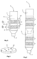
- Figure 1 shows a schematic representation of the device according to the invention.
- At least two containers are connected with one another ( Figure 2 ).
- the outlet of one container may be connected to the inlet of said at least second container detachably, for example, by insertion.
- the evaluation unit has a photodiode/light-emitting diode assembly for establishing the transmittance that can be designed as light-emitting diodes and a charge-coupled device (CCD) line or CCD array.
- CCD charge-coupled device
- a spectrometric evaluation of transmittance can also be performed.
- staining by a receptor/particle conjugate and/or receptor/enzyme conjugate with subsequent addition of an enzyme substrate may be effected.
- the receptor concentration in the segments increases from the inlet 3 to the outlet 4.
- the present invention also relates to a process for performing quantitative affinity-chromatographical quick tests for the presence of analytes using photometric evaluation wherein a solution containing or suspected to contain an analyte is introduced through the inlet 3 of container 1 of the device according to the invention and contacted with the filler material in segments 8 and, following adsorption of the analyte to receptors having affinity for said analyte, the presence of the analyte bound to the receptors is assayed quantitatively and/or qualitatively.
- porous filler material is preferably employed in the form of filter segments on the inner surface of which receptors are immobilized.
- at least two of these elements may be arranged in succession in one tube and separated by liquid-permeable separator elements having reflecting properties on the interface towards the filter element ( Figure 1 ).
- the linear arrangement is flowed through successively by the solution containing the analyte (ligand) to be determined.
- Figure 1 shows a separator disk 6 having one or two reflecting major surfaces.
- the inserted filter elements 2 ( Figure 1 ) have a reflecting inner surface.
- the mean pore diameters should be within a range of from 1 ⁇ m to 100 ⁇ m, and the pore volume fraction is to be from 20% to 80%.
- column-shaped receptor-containing filter elements 2 having a length within a range of from 0.5 to 5 mm and a diameter within a range of from 0.5 to 5 mm are employed.
- the separator elements 6 have the same diameters, but a lower thickness within a range of from 10 ⁇ m to 2.5 mm.
- each receptor-containing filter element 2 is bounded by two separator elements 6 on the top and bottom thereof.
- a substantially higher number of filter elements 2 and separator elements 6 may be arranged in succession.
- the solution containing the ligand to be assayed can flow at a rate of from 1.5 ml/min to 0.01 ml/min with a correspondingly sized metering device or by hydrostatic pressure alone, wherein the specific concentration of the receptor on the active receptor-containing filter elements should be selected within a range of from 2 ⁇ g/ml to 200 mg/ml of filter volume.
- the quantification of the bound ligand is effected separately on the successively arranged filter elements 2 in a per se known manner.
- one or more per se known marker reagents such as immuno, gold, antibody, stain conjugates, antibody-enzyme conjugates etc. that react with the ligand and form a readily detectable, especially by optical detection, complex or catalyze the formation of a detectable colored matter may usually be additionally added before the measurement.
- the change in transmittance of or the light scattered at a defined angle from the individual filter elements is recorded.
- the intensity values of the transmitted or scattered light of values derived therefrom, especially the optical densities calculated according to the stated equation, of at least two successive filter segments 2 are determined for calibration. Subsequently, derived measuring values, which are employed for establishing the calibration, are produced by combining these values on the basis of a suitable mathematical function.
- a simple form of combination is the summation or conversion to mean values of the OD values from the two filters.
- Typical measuring set-ups for the quantification of the transmitted or scattered light are photodiodes/light-emitting diodes assemblies or light-emitting diode cells in combination with CCD lines or CCD arrays.
- Example 2 shows for an analogous three-layered set-up that very good coefficients of variation and thus a precision that is clearly superior to that of the conventional set-up can also be achieved with this process.
- Example 3 the optical detection was effected with a CCD array.
- the Example shows at the same time that it is possible to arrange several segment assemblies having different specificities in succession and thus to perform multiplex analyses.
- Example of Figure 4 a set-up is shown in which the receptor concentration on the filter segments increases from the inlet to the outlet. In this case, a relatively uniform color along the segment column whose length correlates with the analyte concentration is to be noted.
- FIG 4 Photometric calibration curves for the immunological determination of F . tularensis on a porous filter element with immobilized anti- F . tularensis antibody and peroxidase/TMB detection (heterogeneous immunoassay according to Example 1).
- Sintered parts consisting of High Density Polyethylene (HDPE) with a mean pore diameter of 40 ⁇ m and a pore volume fraction of 50% in the dimensions (diameter ⁇ length) 5 ⁇ 5 mm (type 1) or 5 x 1.65 mm (type 2) on which 9 ⁇ g or 3 ⁇ g each, respectively, of monoclonal anti -Francescella tularensis antibodies was immobilized were employed.
- Analogous filter elements in the dimensions 5 x 0.5 mm (type 3) without binding activity (block filters) were employed as porous separator elements.
- F. tularensis extracted lipopolysaccharide was used as the control material.
- concentration was stated on the basis of the germ numbers in cfu/ml before the extraction.
- the assays were performed in pipetting racks with a zero control and 6 calibrating samples each in duplicate. The addition of the sample and of all the subsequent reagents was effected directly into the inlet of the microcolumn. The flow rates were within a range of from 250 to 300 ⁇ l/min. After the binding of the sample (500 ⁇ l), an immune complex was formed on the column by adding anti- F . tularensis- POD conjugate and detected by precipitating TMB and subsequently quantified by transmittance measurement.
- the assay scheme is as follows:
- the optical read-out of the reference columns was effected with a miniphotometer (SENOVA Cat. No. 30010001RDR). It is capable of realizing transmittance measurements on one-layered columns at a wavelength of 532 nm and an aperture diameter of 3.6 mm.
- the multilayer columns were measured with a modified photometer of the same fundamental design. It had a modified measuring head with 3 beam paths (aperture diameter 1.2 mm), each on the level of the active filter elements.
- the OD values were calculated on the basis of formula 1. These OD values and the OD mean values calculated therefrom were shown as a function of the LPS concentration in Figure 4 .
- the upper part shows the calibration curve of the one-layered system, the middle part shows the calibration of the individual filter layers, and the bottom part shows the calibration on the basis of the summed OD values.
- Sintered parts consisting of HDPE with a mean pore diameter of 40 ⁇ m and a pore volume fraction of 50% in the dimensions (diameter ⁇ length) 5 ⁇ 5 mm (type 1) or 5 x 1.65 mm (type 2) on which 15 ⁇ g or 5 ⁇ g each, respectively, of polyclonal affinity-purified serum from rabbit against Streptococcus mutans was immobilized were employed.
- Disks according to Figure 3 were employed as separator elements. They had a metallic surface with partially reflecting properties.
- block filters according to type 3 in Example 1 were employed.
- Cell culture material of S. mutans was used as the control material.
- concentration in cfu/ml was determined by plating.
- the assays were performed in pipetting racks with a zero control and 6 calibrating samples each in duplicate.
- the addition of the sample and of all the subsequent reagents was effected directly into the inlet of the microcolumn.
- the flow rates were within a range of from 180 to 200 ⁇ l/min.
- an immune complex was formed on the column by adding affinity-purified biotinylated anti- S . mutans serum (rabbit).
- streptavidin-magnetic particles 0.5 to 1 ⁇ m, Chemagen GmbH, Baesweiler, Germany
- the magnet particles can be well detected on the filters by photometry by transmittance measurement at 525 nm.
- the assay scheme is as follows:
- Table 1 shows the obtained calibration data as mean values.
- Table 1 Calibration values (mean values from duplicate determinations) for the S. mutans test on a one-layered filter (type 1) and the three-layered filter assembly and the sums and mean values calculated therefrom cfu/ml OD one layer OD filter 1 OD filter 2 OD filter 3 sum mean value 0 0.53 0.036 0.037 0.033 0.106 0.035 1.00 ⁇ 10 3 0.097 0.088 0.061 0.039 0.188 0.063 1.00 ⁇ 10 4 0.177 0.184 0.11 0.42 0.714 0.238 1.00 ⁇ 10 5 0.586 0.552 0.411 0.214 1.177 0.392 1.00 ⁇ 10 6 1.129 1.022 0.673 0.341 2.036 0.679 1.00 ⁇ 10 7 1.86 1.682 1.249 0.663 3.594 1.198 1.00 ⁇ 10 8 2.0025 1.806 1.601 1.002 4.409 1.470 1.00 ⁇ 10
- Example 3 Simultaneous assay of F. tularensis and Y. pestis
- Sintered parts consisting of HDPE with a mean pore diameter of 12 ⁇ m and a pore volume fraction of 40% in the dimensions (diameter x length) 2.5 x 1.6 mm were employed.
- Some of the filters were coated with 2 ⁇ g of monoclonal antibody against F . tularensis (type 1"), and some of the filters were coated with 2 ⁇ g of monoclonal antibody against the F1 antigen of Y. pestis (type 2").
- block filters in the dimensions 2.5 mm x 1.6 mm were employed.
- a multilayer assembly corresponding to Figure 5 and based on 2 parallel tubes connected through a channel was prepared.
- metering with a syringe pump was effected at as flow rate of 1.2 ml/min.
- 1.5 ml of PBS buffer was metered through a second channel of the syringe pump in 5 seconds, followed by metering 500 ⁇ l of precipitating TMB through a third channel in 3 seconds.
- PBS buffer (500 ⁇ l) was again metered through channel 2.
- the optical evaluation was performed in the CCD array assembly as shown in Figure 5 .
- Figure 5 shows the result in a schematic form for an analysis with a high (5000 cfu/ml) F . tularensis concentration and iow Y. pestis concentration (0.2 ng/ml) and the converse case of a low F. tularensis (425 cfu/ml) and high Y. pestis concentration (10 ng/ml).
- the calibrations obtained for the two analytes on the basis of the sums of the calculated OD values of the 6 filters are shown in Figure 6 .
- the filters were coated with 7.5 ⁇ g of monoclonal antibody against Botulinus toxin A.
- HRP horse raddish peroxidase
- Figure 6 shows the result in a schematic form for an analysis with a low (0.5 ng/ml) and high (5 ng/ml) concentration.
- the number of stained filters directly indicates the detected concentration in the sample.
Landscapes
- Health & Medical Sciences (AREA)
- Immunology (AREA)
- Life Sciences & Earth Sciences (AREA)
- Chemical & Material Sciences (AREA)
- Engineering & Computer Science (AREA)
- Physics & Mathematics (AREA)
- Analytical Chemistry (AREA)
- Pathology (AREA)
- Hematology (AREA)
- Molecular Biology (AREA)
- Urology & Nephrology (AREA)
- General Physics & Mathematics (AREA)
- General Health & Medical Sciences (AREA)
- Biochemistry (AREA)
- Biomedical Technology (AREA)
- Biotechnology (AREA)
- Medicinal Chemistry (AREA)
- Food Science & Technology (AREA)
- Cell Biology (AREA)
- Microbiology (AREA)
- Chemical Kinetics & Catalysis (AREA)
- Plasma & Fusion (AREA)
- Investigating Or Analysing Materials By The Use Of Chemical Reactions (AREA)
Description
- The present invention relates to a process and a device for performing quantitative affinity-chromatographical quick tests with photometric evaluation with a porous filler material having a reflecting inner surface and receptors immobilized thereon and being provided in a container having an inlet and outlet.
- Affinity-chromatographical quick tests are based on biospecific interactions of ligands and receptors. Typically, the receptor is immobilized on a surface of a solid while the ligand to be assayed is supplied via a liquid phase and is specifically bound to the surface. A usual construction form for quick tests is described in
U.S. Patent No. 4,943,522 . Such quick tests are employed, for example, as pregnancy test strips. They are prepared on the basis of nitrocellulose strips which are capped by a glass fiber membrane at the upper portion thereof. The sample is applied to the upper portion of the glass fiber membrane and reacts, while it migrates through the non-woven material, with the conjugate incorporated therein. As a rule, these are antibody-gold particles. The immunocomplex formed migrates further through the nitrocellulose membrane and is bound to capture antibodies immobilized thereon. As a result, a stained band is formed. In the past, there have been numerous attempts to read out such test strips quantitatively by either reflectometry or transmittance measurement. However, the sensitivity and precision that can be achieved thereby is relatively poor, and the dynamic range of such measurements is limited to 2-2.5 orders of magnitude. - Another quick test method is described in
EP-A-0 557 288 ,EP-0 634 015 orWO-A-95/19569 DE 102004 006470A1 is employed. Such a procedure is described in Gessler et al., 2005 Appl. Environ. Microbiol. (2005) p7897-7903. This method is dearly superior to the above described membrane method in terms of sensitivity, but likewise it also exhibits a very narrow dynamic range of 2.5 orders of magnitude at most. In the method described, scattered light measurements show a behavior that is comparable in principle. -
WO-A-87/07384 -
EP-A-0021214 discloses a specific binding assay method, and a test device and test kit for use therein, for determining a ligand, such as an antigen or antibody, in, or the ligand binding capacity of, a liquid medium, particularly a body fluid such as serum, wherein the unknown ligand competes with a labeled component, such as a radiolabeled form of the ligand or of a binding analog of the ligand, for binding with a binding partner, and wherein separation of the resulting bound-species and free-species of the labeled component is accomplished by allowing the liquid reaction mixture to be drawn by capillary action into a column comprising a bed of an adsorbent material selective for one of the two species. The improvement comprises using a column containing at least one additional bed of capillarily absorbent material disposed above said absorbent bed and which is substantially nonadsorbent relative to the one of said two species which said adsorbent bed selectively binds. The use of specific types of capillarily absorbent beds in addition to the selectively absorbent bed to form multilayer columns overcomes several unforeseen problems encountered in using the previously known column chromatography method for certain assay applications. - Alternative reading-out techniques, such as fluorometry and luminometry, have a better dynamic range of up to 4 orders of magnitude. Generally, however, the necessary measuring technology is relatively tedious and thus expensive in these methods. In addition, interference may occur from quenching and bleaching effects. Therefore, in contrast to photometry, these techniques are not suitable for the preparation of simple and inexpensive measuring systems.
- With analytes occurring in a broader range of concentrations, the narrow dynamic range of the photometric methods in turn has the result that several dilutions of the solution to be analyzed would have to be prepared and examined for one analysis. This procedure is not user-friendly and has the consequence that the quick test method cannot be employed.
- It was the object of the invention to provide a process and a corresponding device which allow analytes to be assayed quickly and precisely by affinity chromatography in a broad dynamic range on the basis of a simple, inexpensive optical transmission technique.
- The above object is achieved by a device according to
claim 1 and a process according toclaim 10. The dependent claims relate to particular embodiments of the device according to the invention.
(Appl. Environ. Microbiol. (2005) p7897-7903) - The device according to the invention is suitable for performing quantitative affinity-chromatographical quick tests with photometric evaluation. The device includes at least one
filter element 2 formed from aporous filler material 5 on which receptors are immobilized and which is provided in acontainer 1 having aninlet 3 and anoutlet 4. Thefilter element 2 has a reflecting inner surface. The device according to the invention is characterized in that: - the
porous filler material 5 is provided between two liquid-permeable separator elements 6 to form a column-shaped segment 8; - at least two column-
shaped segments 8 are provided in the device; - the receptors are in a specific concentration within a range of from 1 ng/ml to 200 g/ml of filter volume;
- the
separator elements 6 have reflecting properties on the surface adjacent to the porous filler material; - the separator element (6) is a
porous filter element 2 having a mean pore diameter of from 1 to 100 µm and a pore volume fraction of from 20% to 80%; - the device has such a design as to allow the device to be flowed through by a solution containing analytes that can be bound to receptors immobilized at the surface of the porous filler materials at a rate within a range of from 1.5 ml/min to 0.01 ml/min;
- the device has a
means 10 with analytes bound to receptors immobilized at the surface of the porous filler materials that is quantified on one ormore segments 8 by light transmittance measurement or/and light scattering measurement at an angle of between 180° and 90° either directly of upon addition of one or more secondary reagents undergoing specific binding with the analytes to produce a color directly or indirectly; - wherein the device has an evaluation unit that allows the amount of analyte to be assayed by means of a calibration curve taking into account the transmittance or values derived therefrom of at least two segments.
- In one embodiment, the
segments 8 containing the porous filler material have a length of from 0.5 to 10 mm and a diameter of from 0.5 to 5 mm. -
Figure 1 shows a schematic representation of the device according to the invention. - It may be advantageous if at least two containers are connected with one another (
Figure 2 ). The outlet of one container may be connected to the inlet of said at least second container detachably, for example, by insertion. - In a further embodiment of the device according to the invention, the evaluation unit has a photodiode/light-emitting diode assembly for establishing the transmittance that can be designed as light-emitting diodes and a charge-coupled device (CCD) line or CCD array.
- A spectrometric evaluation of transmittance can also be performed.
- For detecting the analyte, staining by a receptor/particle conjugate and/or receptor/enzyme conjugate with subsequent addition of an enzyme substrate may be effected.
- In another embodiment of the device according to the invention, the receptor concentration in the segments increases from the
inlet 3 to theoutlet 4. - The present invention also relates to a process for performing quantitative affinity-chromatographical quick tests for the presence of analytes using photometric evaluation wherein a solution containing or suspected to contain an analyte is introduced through the
inlet 3 ofcontainer 1 of the device according to the invention and contacted with the filler material insegments 8 and, following adsorption of the analyte to receptors having affinity for said analyte, the presence of the analyte bound to the receptors is assayed quantitatively and/or qualitatively. - The invention is described in more detail in the following.
- We explicitly proceed from the process described above on the basis of a photometric measuring cuvette with a heterogeneous porous filler material. The porous filler material is preferably employed in the form of filter segments on the inner surface of which receptors are immobilized. According to the invention, at least two of these elements may be arranged in succession in one tube and separated by liquid-permeable separator elements having reflecting properties on the interface towards the filter element (
Figure 1 ). The linear arrangement is flowed through successively by the solution containing the analyte (ligand) to be determined. -
Figure 1 shows aseparator disk 6 having one or two reflecting major surfaces. - In particular, the inserted filter elements 2 (
Figure 1 ) have a reflecting inner surface. The mean pore diameters should be within a range of from 1 µm to 100 µm, and the pore volume fraction is to be from 20% to 80%. - In one embodiment according to the invention, column-shaped receptor-containing
filter elements 2 having a length within a range of from 0.5 to 5 mm and a diameter within a range of from 0.5 to 5 mm are employed. Theseparator elements 6 have the same diameters, but a lower thickness within a range of from 10 µm to 2.5 mm. Generally, each receptor-containingfilter element 2 is bounded by twoseparator elements 6 on the top and bottom thereof. In a simple embodiment according to the invention, the following sequence is obtained: -
separator element 6/active filter element 2/separator element 6/active filter element 2/separator element 6. - In a further embodiment of the device according to the invention in the form of an analytical tube, a substantially higher number of
filter elements 2 andseparator elements 6 may be arranged in succession. Through the linear arrangement that can be flowed through, the solution containing the ligand to be assayed can flow at a rate of from 1.5 ml/min to 0.01 ml/min with a correspondingly sized metering device or by hydrostatic pressure alone, wherein the specific concentration of the receptor on the active receptor-containing filter elements should be selected within a range of from 2 µg/ml to 200 mg/ml of filter volume. - The quantification of the bound ligand is effected separately on the successively arranged
filter elements 2 in a per se known manner. For this purpose, one or more per se known marker reagents, such as immuno, gold, antibody, stain conjugates, antibody-enzyme conjugates etc. that react with the ligand and form a readily detectable, especially by optical detection, complex or catalyze the formation of a detectable colored matter may usually be additionally added before the measurement. According to the invention, the change in transmittance of or the light scattered at a defined angle from the individual filter elements is recorded. Optical densities can be calculated therefrom on the basis of the Lambert-Beer law. Namely:
where: - OD = optical density
- ε = extinction coefficient
- deff = effective layer thickness, which depends on the light-scattering properties of the filters;
- c = concentration of the analyte to be assayed;
- I0 = transmittance before the filter element is stained with the labeling substance;
- I = transmittance after the filter element has been stained with the labeling substance.
- According to the invention, the intensity values of the transmitted or scattered light of values derived therefrom, especially the optical densities calculated according to the stated equation, of at least two
successive filter segments 2 are determined for calibration. Subsequently, derived measuring values, which are employed for establishing the calibration, are produced by combining these values on the basis of a suitable mathematical function. A simple form of combination is the summation or conversion to mean values of the OD values from the two filters. - It has been found that a calibration function having a broader dynamic range than that obtained from the evaluation of a single filter under comparable reaction conditions can be generated by plotting these derived values against the concentration.
- Thus, an extension of the measuring range of up to 4 powers of ten, i.e., dynamic ranges of up to 6 powers of ten, in concentration can be realized. To achieve this, more than two
filter segments 2 should usually be provided in succession, wherein such filter segments can have a very thin design. Typical measuring set-ups for the quantification of the transmitted or scattered light are photodiodes/light-emitting diodes assemblies or light-emitting diode cells in combination with CCD lines or CCD arrays. - The procedure described is illustrated in
Figure 4 taking a three-layered filter set-up as an example in comparison with a one-layered conventional set-up. In the example shown, the volume of the individual reference filter corresponds to the sum of the filter volumes of the three smaller filters in the multifilter set-up. The Figure is based on the data from Example 1. - Example 2 shows for an analogous three-layered set-up that very good coefficients of variation and thus a precision that is clearly superior to that of the conventional set-up can also be achieved with this process.
- In the case of Example 3, the optical detection was effected with a CCD array. The Example shows at the same time that it is possible to arrange several segment assemblies having different specificities in succession and thus to perform multiplex analyses.
- In the Example of
Figure 4 , a set-up is shown in which the receptor concentration on the filter segments increases from the inlet to the outlet. In this case, a relatively uniform color along the segment column whose length correlates with the analyte concentration is to be noted. -
Figure 4 : Photometric calibration curves for the immunological determination of F. tularensis on a porous filter element with immobilized anti-F. tularensis antibody and peroxidase/TMB detection (heterogeneous immunoassay according to Example 1). - Top: Calibration curve and optical set-up of a conventional measuring assembly based on a 5 x 5 mm polyethylene filter element and a single-beam photometer.
- Middle: Calibration curves and optical set-up for an assembly proposed according to the invention of three filter elements of 1.6 x 5 mm separated by separator elements and the corresponding photometric three-layer set-up; the calibration curves were respectively established on the filter elements and may be used singly or on the basis of suitable mathematical combinations for evaluating the measurement.
- Bottom: Summed calibration curve calculated from the 3 calibration curves for the F. tularensis determination on the set-up proposed according to the invention.
- Sintered parts consisting of High Density Polyethylene (HDPE) with a mean pore diameter of 40 µm and a pore volume fraction of 50% in the dimensions (diameter × length) 5 × 5 mm (type 1) or 5 x 1.65 mm (type 2) on which 9 µg or 3 µg each, respectively, of monoclonal anti-Francescella tularensis antibodies was immobilized were employed. Analogous filter elements in the dimensions 5 x 0.5 mm (type 3) without binding activity (block filters) were employed as porous separator elements.
- By inserting a
type 1 filter element into microcolumns (d = 5 mm, V = 750 µl), an assembly corresponding to the scheme on the top ofFigure 2 was prepared. This one-layered assembly corresponds to the above described prior art and served as a reference system. - The preparation of the multilayered assembly proposed according to the invention in accordance with the middle and bottom of
Figure 2 was effected by sequential insertion according to the scheme: -
Filter type 3/type 2/type 3/type 2/type 3/type 2/type 3. - F. tularensis extracted lipopolysaccharide was used as the control material. The concentration was stated on the basis of the germ numbers in cfu/ml before the extraction. The assays were performed in pipetting racks with a zero control and 6 calibrating samples each in duplicate. The addition of the sample and of all the subsequent reagents was effected directly into the inlet of the microcolumn. The flow rates were within a range of from 250 to 300 µl/min. After the binding of the sample (500 µl), an immune complex was formed on the column by adding anti-F. tularensis-POD conjugate and detected by precipitating TMB and subsequently quantified by transmittance measurement. The assay scheme is as follows:
- ● 500 µl sample in pphosphate buffered saline (PBS) buffer
- ● incubation for 4 min
- ● 500 µl of anti-F. tularensis-poly-HRP conjugate (8 µg/ml)
- ● incubation for 4 min
- ● 2 x 750 µl PBS buffer
- ● determination of transmittance I0
- ● 500 µl of TMB substrate solution precipitating
- ● incubation for 6 min
- ● 500 µl of PBS buffer
- ● determination of transmittance I
- The optical read-out of the reference columns was effected with a miniphotometer (SENOVA Cat. No. 30010001RDR). It is capable of realizing transmittance measurements on one-layered columns at a wavelength of 532 nm and an aperture diameter of 3.6 mm. The multilayer columns were measured with a modified photometer of the same fundamental design. It had a modified measuring head with 3 beam paths (aperture diameter 1.2 mm), each on the level of the active filter elements.
- From the measured transmittance values, the OD values were calculated on the basis of
formula 1. These OD values and the OD mean values calculated therefrom were shown as a function of the LPS concentration inFigure 4 . The upper part shows the calibration curve of the one-layered system, the middle part shows the calibration of the individual filter layers, and the bottom part shows the calibration on the basis of the summed OD values. - Sintered parts consisting of HDPE with a mean pore diameter of 40 µm and a pore volume fraction of 50% in the dimensions (diameter × length) 5 × 5 mm (type 1) or 5 x 1.65 mm (type 2) on which 15 µg or 5 µg each, respectively, of polyclonal affinity-purified serum from rabbit against Streptococcus mutans was immobilized were employed.
- Disks according to
Figure 3 were employed as separator elements. They had a metallic surface with partially reflecting properties. In addition, block filters according totype 3 in Example 1 were employed. - By inserting a
type 1 filter element into microcolumns (d = 5 mm, V = 750 µl), an assembly corresponding to the scheme ofFigure 4 (top) was prepared. This one-layered assembly corresponds to the above described prior art and served as a reference system. The preparation of the multilayered assembly proposed according to the invention in accordance with the middle and bottom ofFigure 4 was effected by sequential insertion according to the scheme: -
Type 3/type 2/disk/type 2'/disk/type 2/type 3'. - Cell culture material of S. mutans was used as the control material. The concentration in cfu/ml was determined by plating. The assays were performed in pipetting racks with a zero control and 6 calibrating samples each in duplicate. The addition of the sample and of all the subsequent reagents was effected directly into the inlet of the microcolumn. The flow rates were within a range of from 180 to 200 µl/min. After the binding of the sample (500 µl), an immune complex was formed on the column by adding affinity-purified biotinylated anti-S. mutans serum (rabbit). Subsequently, streptavidin-magnetic particles (0.5 to 1 µm, Chemagen GmbH, Baesweiler, Germany) were added for optical detection. The magnet particles can be well detected on the filters by photometry by transmittance measurement at 525 nm. The assay scheme is as follows:
- ● 500 µl sample
- ● incubation for 4 min
- ● 500 µl of anti-S mutans-biotin (Immunoglobulin
G IgG fraction 8 µg/ml) - ● incubation for 4 min
- ● determination of transmittance I0
- ● 500 µl of streptavidin-magnetic particles (Chemagen)
- ● 750 µl of PBS buffer
- ● determination of transmittance I*
- The determination of the transmittance values was effected as described in Example 1. The following Table 1 shows the obtained calibration data as mean values.
Table 1: Calibration values (mean values from duplicate determinations) for the S. mutans test on a one-layered filter (type 1) and the three-layered filter assembly and the sums and mean values calculated therefrom cfu/ml OD one layer OD filter 1 OD filter 2OD filter 3sum mean value 0 0.53 0.036 0.037 0.033 0.106 0.035 1.00·103 0.097 0.088 0.061 0.039 0.188 0.063 1.00·104 0.177 0.184 0.11 0.42 0.714 0.238 1.00·105 0.586 0.552 0.411 0.214 1.177 0.392 1.00·106 1.129 1.022 0.673 0.341 2.036 0.679 1.00·107 1.86 1.682 1.249 0.663 3.594 1.198 1.00·108 2.0025 1.806 1.601 1.002 4.409 1.470 1.00·109 2.0965 1.917 1.722 1.239 4.878 1.626 - Sintered parts consisting of HDPE with a mean pore diameter of 12 µm and a pore volume fraction of 40% in the dimensions (diameter x length) 2.5 x 1.6 mm were employed. Some of the filters were coated with 2 µg of monoclonal antibody against F. tularensis (
type 1"), and some of the filters were coated with 2 µg of monoclonal antibody against the F1 antigen of Y. pestis (type 2"). The separator elements were prepared from 0.15 mm thick aluminum foil that was provided with 3 holes each (d = 0.2 mm). In addition, block filters in the dimensions 2.5 mm x 1.6 mm were employed. - A multilayer assembly corresponding to
Figure 5 and based on 2 parallel tubes connected through a channel was prepared. The sample (500 µl) was preincubated with 4 µg of anti-F. tularensis-POD conjugate (POD = β-peroxidase) and 3 µg of antl-Y. pestis-POD conjugate for 6 minutes. Subsequently, metering with a syringe pump was effected at as flow rate of 1.2 ml/min. Subsequently, 1.5 ml of PBS buffer was metered through a second channel of the syringe pump in 5 seconds, followed by metering 500 µl of precipitating TMB through a third channel in 3 seconds. After an incubation time of 4 minutes, PBS buffer (500 µl) was again metered throughchannel 2. Subsequently, the optical evaluation was performed in the CCD array assembly as shown inFigure 5 . - In an exemplary manner,
Figure 5 shows the result in a schematic form for an analysis with a high (5000 cfu/ml) F. tularensis concentration and iow Y. pestis concentration (0.2 ng/ml) and the converse case of a low F. tularensis (425 cfu/ml) and high Y. pestis concentration (10 ng/ml). The calibrations obtained for the two analytes on the basis of the sums of the calculated OD values of the 6 filters are shown inFigure 6 . - Eleven sintered parts consisting of HDPE with a mean pore diameter of 12 µm and a pore volume fraction of 40% in the dimensions (diameter x length) 1 x 1.6 mm were employed.
- The filters were coated with 7.5 µg of monoclonal antibody against Botulinus toxin A. The separator elements were prepared from 0.15 mm thick aluminum foil that was provided with 3 holes each (d = 0.2 mm).
- A multilayer assembly corresponding to
Figure 6 was prepared. - The sample (900 µl) was preincubated with 4 µg of biotinylated anti-BotA antibody for 6 minutes. Subsequently, the metering was effected by feeding onto the column at a flow rate of about 0.4 ml/min. Subsequently, 500 µl of SA-polyHRP (HRP = horse raddish peroxidase) was pipetted, the column was washed twice with 1.5 ml of PBS buffer after 6 minutes, followed by metering 500 µl of precipitating TMBN in about 1.25 minutes. After an incubation time of 6 minutes, 1 ml of PBS buffer was again metered. Subsequently, the optical evaluation was performed by a CCD array assembly.
- In an exemplary manner,
Figure 6 shows the result in a schematic form for an analysis with a low (0.5 ng/ml) and high (5 ng/ml) concentration. The number of stained filters directly indicates the detected concentration in the sample.
Claims (9)
- A device for performing quantitative affinity-chromatographical quick tests with photometric evaluation including at least one filter element (2) formed from a porous filler material (5) on which receptors are immobilized and which is provided in a container (1) having an inlet (3) and an outlet (4), said filter element (2) having a reflecting inner surface, characterized in that:- the porous filler material (5) is provided between two liquid-permeable separator elements (6) to form a column-shaped segment (8);- at least two column-shaped segments (8) are provided in the device;- the receptors are in a specific concentration within a range of from 1 ng/ml to 200 g/ml of filter volume;- the separator elements (6) have reflecting properties on the surface adjacent to the porous filler material;- the separator element (6) is a porous filter element having a mean pore diameter of from 1 to 100 µm and a pore volume fraction of from 20% to 80%;- the device has such a design as to allow the device to be flowed through by a solution containing analytes that can be bound to receptors immobilized at the surface of the porous filler materials at a rate within a range of from 1.5 ml/min to 0.01 ml/min;- the device has a means (10) with which analytes bound to receptors immobilized at the surface of the porous filler materials are quantified on one or more segments (8) by light transmittance measurement or/and light scattering measurement at an angle of between 180° and 90° either directly or upon addition of one or more reagents which specifically bind with the analytes to produce a color directly or indirectly;- wherein the device has an evaluation unit that allows the amount of analyte to be assayed by means of a calibration curve taking into account the transmittance or values derived therefrom of at least two segments.
- The device according to claim 1, characterized in that the segments (8) containing the porous filler material have a length of from 0.5 to 10 mm and a diameter of from 0.5 to 5 mm.
- The device according to claim 1 and/or 2, characterized in that at least two devices are connected with one another.
- The device according to at least one of claims 1 to 3, characterized in that the evaluation unit has a photodiode/light-emitting diode assembly for establishing the transmittance.
- The device according to at least one of claims 1 to 4, characterized in that the evaluation unit has an assembly of light-emitting diodes and a CCD line or CCD array for establishing the transmittance.
- The device according to at least one of claims 1 to 5, characterized in that the staining is effected by a receptor-particle conjugate.
- The device according to at least one of claims 1 to 6, characterized in that the staining is effected by a receptor-enzyme conjugate followed by adding an enzyme substrate.
- The device according to claims 1 to 7, characterized in that the receptor concentration in the segments increases from the inlet (3) to the outlet (4).
- A process for performing quantitative affinity-chromatographical quick tests for the presence of analytes using photometric evaluation wherein a solution containing or suspected to contain an analyte is introduced through the inlet of the device according to any of claims 1 to 8 and contacted with the porous filler material in segments (8) and, following adsorption of the analyte to receptors having affinity for said analyte, the presence of the analyte bound to the receptors is assayed quantitatively and/or qualitatively.
Applications Claiming Priority (2)
| Application Number | Priority Date | Filing Date | Title |
|---|---|---|---|
| DE200710025311 DE102007025311A1 (en) | 2007-05-30 | 2007-05-30 | Quantitative heterogeneous fast binding assay with broad dynamic range and simple photometric detection |
| PCT/EP2008/056675 WO2008145722A1 (en) | 2007-05-30 | 2008-05-30 | Device and process for binding assays |
Publications (2)
| Publication Number | Publication Date |
|---|---|
| EP2149048A1 EP2149048A1 (en) | 2010-02-03 |
| EP2149048B1 true EP2149048B1 (en) | 2012-11-07 |
Family
ID=39731474
Family Applications (1)
| Application Number | Title | Priority Date | Filing Date |
|---|---|---|---|
| EP08760265A Not-in-force EP2149048B1 (en) | 2007-05-30 | 2008-05-30 | Device and process for binding assays |
Country Status (3)
| Country | Link |
|---|---|
| EP (1) | EP2149048B1 (en) |
| DE (1) | DE102007025311A1 (en) |
| WO (1) | WO2008145722A1 (en) |
Families Citing this family (6)
| Publication number | Priority date | Publication date | Assignee | Title |
|---|---|---|---|---|
| EP2264461A1 (en) * | 2009-06-19 | 2010-12-22 | FZMB GmbH Forschungszentrum für Medizintechnik und Biotechnologie | Device for executing an affinity chromatographic sample test |
| US8648016B2 (en) * | 2010-02-08 | 2014-02-11 | Robert Bosch Gmbh | Array with extended dynamic range and associated method |
| CN102213717A (en) * | 2010-04-02 | 2011-10-12 | 王立莉 | Immune nano-particle chromatographic measuring method and device for implementing method |
| CN103547922B (en) * | 2011-02-11 | 2016-06-08 | Fzmb医疗技术和生物技术研究中心有限公司 | Method for detecting cells from a sample |
| DE102016015171B4 (en) | 2016-12-20 | 2021-04-01 | Albert-Ludwigs-Universität Freiburg | Analysis device with functionalized cryogels |
| EP4446007B1 (en) | 2023-04-13 | 2025-09-10 | VELLAP Diagnostics GmbH | Rapid-test chromatographic set for screening a sample for pathogens, biomolecules, biomarkers, and chemical substances |
Family Cites Families (7)
| Publication number | Priority date | Publication date | Assignee | Title |
|---|---|---|---|---|
| US4301139A (en) | 1979-06-21 | 1981-11-17 | Ames-Yissum Ltd. | Multilayer column chromatography specific binding assay method, test device and test kit |
| AU7033787A (en) | 1986-05-30 | 1987-12-22 | Quidel | Enzyme immunoassay device |
| US4943522A (en) | 1987-06-01 | 1990-07-24 | Quidel | Lateral flow, non-bibulous membrane assay protocols |
| DE4126436A1 (en) | 1990-09-17 | 1992-03-19 | Abion Ohg | DISPOSABLE REACTION TUBE FOR SOLID-PHASE IMMUNAL ANALYTICS AND METHOD FOR MEASURING COMPONENTS DETERMINABLE BY IMMUNE REACTIONS |
| DE4208732C2 (en) | 1992-03-18 | 1995-04-27 | Abion Ohg | Disposable reaction vessel for solid phase immunoanalysis and method for measuring components that can be determined via immune reactions |
| JPH09507577A (en) | 1994-01-13 | 1997-07-29 | アビオン ベタイリゲンズ− ウント ベルワルトゥングスゲゼルシャフト ミット ベシュレンクテル ハフツング | Reaction column and method for multi-target simultaneous measurement |
| DE102004006470B4 (en) | 2004-02-06 | 2006-06-01 | Senova Gesellschaft für Biowissenschaft und Technik mbH | Absorption photometric method for quantitative substance analysis |
-
2007
- 2007-05-30 DE DE200710025311 patent/DE102007025311A1/en not_active Withdrawn
-
2008
- 2008-05-30 WO PCT/EP2008/056675 patent/WO2008145722A1/en not_active Ceased
- 2008-05-30 EP EP08760265A patent/EP2149048B1/en not_active Not-in-force
Also Published As
| Publication number | Publication date |
|---|---|
| DE102007025311A1 (en) | 2008-12-04 |
| EP2149048A1 (en) | 2010-02-03 |
| WO2008145722A1 (en) | 2008-12-04 |
Similar Documents
| Publication | Publication Date | Title |
|---|---|---|
| US5674699A (en) | Two-phase optical assay | |
| US5569608A (en) | Quantitative detection of analytes on immunochromatographic strips | |
| EP0026176B1 (en) | Double tagged immunoassay | |
| US8093057B2 (en) | System for quantitative measurement of glycohemoglobin and method for measuring glycohemoglobin | |
| CA2249303C (en) | Chromatographic immunoassay device and method utilizing particle valency for quantitation | |
| US20040018576A1 (en) | Bence Jones protein testing cassette | |
| EP0987551A2 (en) | Method for the determination of analyte concentration in a lateral flow sandwich immunoassay exhibiting high-dose hook effect | |
| US6689317B1 (en) | Immunoassay apparatus for diagnosis | |
| NO331708B1 (en) | Systems and methods for performing magnetic chromatography analyzes | |
| JPH01308946A (en) | Method and apparatus for detecting low- concentration biochemical component existing in test medium using surface plasmon resonance | |
| EP2149048A1 (en) | Device and process for binding assays | |
| CA2585002A1 (en) | Rapid microfluidic assay for analyte interactions | |
| KR100455298B1 (en) | Immunochromatographic assay device having transparent plastic backing and method for producing the same | |
| CN109459574A (en) | For detecting the immuno-chromatographic test paper strip of saccharification hemoglobin content and comprising its immunoassay detection device | |
| KR20190117350A (en) | Lateral flow assay strip | |
| JP2000321277A (en) | Chromatographic quantitative measurement device | |
| EP2031393B1 (en) | Sensor element for spr measurement | |
| WO1997034148A1 (en) | Immunoassay device | |
| CA2475456A1 (en) | Method and device to optimize analyte and antibody substrate binding by least energy adsorption | |
| US20020182748A1 (en) | Method and device for testing for Bence-Jones Protein | |
| EP0902287A1 (en) | Formulation for reducing urea effect for immunochromatography assays using urine samples | |
| CN106198964A (en) | A kind of cassette protein chip and application thereof | |
| US5232663A (en) | Test carrier for analytical determination having a highly effective fixing layer for flow-through bound/free separation | |
| US8039268B2 (en) | Immunochromatoassay method and immunochromatoassay kit | |
| CA2210794A1 (en) | Immunoassay method and reagent involving suspendible carbon labelled bioaffine particles |
Legal Events
| Date | Code | Title | Description |
|---|---|---|---|
| PUAI | Public reference made under article 153(3) epc to a published international application that has entered the european phase |
Free format text: ORIGINAL CODE: 0009012 |
|
| 17P | Request for examination filed |
Effective date: 20091123 |
|
| AK | Designated contracting states |
Kind code of ref document: A1 Designated state(s): AT BE BG CH CY CZ DE DK EE ES FI FR GB GR HR HU IE IS IT LI LT LU LV MC MT NL NO PL PT RO SE SI SK TR |
|
| AX | Request for extension of the european patent |
Extension state: AL BA MK RS |
|
| 17Q | First examination report despatched |
Effective date: 20100621 |
|
| DAX | Request for extension of the european patent (deleted) | ||
| REG | Reference to a national code |
Ref country code: DE Ref legal event code: R079 Ref document number: 602008019963 Country of ref document: DE Free format text: PREVIOUS MAIN CLASS: G01N0033543000 Ipc: G01N0021780000 |
|
| RIC1 | Information provided on ipc code assigned before grant |
Ipc: G01N 21/78 20060101AFI20120209BHEP Ipc: G01N 33/538 20060101ALI20120209BHEP Ipc: G01N 33/543 20060101ALI20120209BHEP |
|
| GRAP | Despatch of communication of intention to grant a patent |
Free format text: ORIGINAL CODE: EPIDOSNIGR1 |
|
| GRAJ | Information related to disapproval of communication of intention to grant by the applicant or resumption of examination proceedings by the epo deleted |
Free format text: ORIGINAL CODE: EPIDOSDIGR1 |
|
| GRAS | Grant fee paid |
Free format text: ORIGINAL CODE: EPIDOSNIGR3 |
|
| GRAP | Despatch of communication of intention to grant a patent |
Free format text: ORIGINAL CODE: EPIDOSNIGR1 |
|
| GRAA | (expected) grant |
Free format text: ORIGINAL CODE: 0009210 |
|
| AK | Designated contracting states |
Kind code of ref document: B1 Designated state(s): AT BE BG CH CY CZ DE DK EE ES FI FR GB GR HR HU IE IS IT LI LT LU LV MC MT NL NO PL PT RO SE SI SK TR |
|
| REG | Reference to a national code |
Ref country code: GB Ref legal event code: FG4D |
|
| REG | Reference to a national code |
Ref country code: AT Ref legal event code: REF Ref document number: 583201 Country of ref document: AT Kind code of ref document: T Effective date: 20121115 Ref country code: CH Ref legal event code: EP |
|
| REG | Reference to a national code |
Ref country code: IE Ref legal event code: FG4D |
|
| REG | Reference to a national code |
Ref country code: DE Ref legal event code: R096 Ref document number: 602008019963 Country of ref document: DE Effective date: 20130103 |
|
| REG | Reference to a national code |
Ref country code: AT Ref legal event code: MK05 Ref document number: 583201 Country of ref document: AT Kind code of ref document: T Effective date: 20121107 |
|
| REG | Reference to a national code |
Ref country code: NL Ref legal event code: VDEP Effective date: 20121107 |
|
| REG | Reference to a national code |
Ref country code: LT Ref legal event code: MG4D |
|
| PG25 | Lapsed in a contracting state [announced via postgrant information from national office to epo] |
Ref country code: SE Free format text: LAPSE BECAUSE OF FAILURE TO SUBMIT A TRANSLATION OF THE DESCRIPTION OR TO PAY THE FEE WITHIN THE PRESCRIBED TIME-LIMIT Effective date: 20121107 Ref country code: IS Free format text: LAPSE BECAUSE OF FAILURE TO SUBMIT A TRANSLATION OF THE DESCRIPTION OR TO PAY THE FEE WITHIN THE PRESCRIBED TIME-LIMIT Effective date: 20130307 Ref country code: NL Free format text: LAPSE BECAUSE OF FAILURE TO SUBMIT A TRANSLATION OF THE DESCRIPTION OR TO PAY THE FEE WITHIN THE PRESCRIBED TIME-LIMIT Effective date: 20121107 Ref country code: NO Free format text: LAPSE BECAUSE OF FAILURE TO SUBMIT A TRANSLATION OF THE DESCRIPTION OR TO PAY THE FEE WITHIN THE PRESCRIBED TIME-LIMIT Effective date: 20130207 Ref country code: FI Free format text: LAPSE BECAUSE OF FAILURE TO SUBMIT A TRANSLATION OF THE DESCRIPTION OR TO PAY THE FEE WITHIN THE PRESCRIBED TIME-LIMIT Effective date: 20121107 Ref country code: HR Free format text: LAPSE BECAUSE OF FAILURE TO SUBMIT A TRANSLATION OF THE DESCRIPTION OR TO PAY THE FEE WITHIN THE PRESCRIBED TIME-LIMIT Effective date: 20121107 Ref country code: LT Free format text: LAPSE BECAUSE OF FAILURE TO SUBMIT A TRANSLATION OF THE DESCRIPTION OR TO PAY THE FEE WITHIN THE PRESCRIBED TIME-LIMIT Effective date: 20121107 |
|
| PG25 | Lapsed in a contracting state [announced via postgrant information from national office to epo] |
Ref country code: BE Free format text: LAPSE BECAUSE OF FAILURE TO SUBMIT A TRANSLATION OF THE DESCRIPTION OR TO PAY THE FEE WITHIN THE PRESCRIBED TIME-LIMIT Effective date: 20121107 Ref country code: LV Free format text: LAPSE BECAUSE OF FAILURE TO SUBMIT A TRANSLATION OF THE DESCRIPTION OR TO PAY THE FEE WITHIN THE PRESCRIBED TIME-LIMIT Effective date: 20121107 Ref country code: GR Free format text: LAPSE BECAUSE OF FAILURE TO SUBMIT A TRANSLATION OF THE DESCRIPTION OR TO PAY THE FEE WITHIN THE PRESCRIBED TIME-LIMIT Effective date: 20130208 Ref country code: PT Free format text: LAPSE BECAUSE OF FAILURE TO SUBMIT A TRANSLATION OF THE DESCRIPTION OR TO PAY THE FEE WITHIN THE PRESCRIBED TIME-LIMIT Effective date: 20130307 Ref country code: SI Free format text: LAPSE BECAUSE OF FAILURE TO SUBMIT A TRANSLATION OF THE DESCRIPTION OR TO PAY THE FEE WITHIN THE PRESCRIBED TIME-LIMIT Effective date: 20121107 Ref country code: PL Free format text: LAPSE BECAUSE OF FAILURE TO SUBMIT A TRANSLATION OF THE DESCRIPTION OR TO PAY THE FEE WITHIN THE PRESCRIBED TIME-LIMIT Effective date: 20121107 |
|
| PG25 | Lapsed in a contracting state [announced via postgrant information from national office to epo] |
Ref country code: AT Free format text: LAPSE BECAUSE OF FAILURE TO SUBMIT A TRANSLATION OF THE DESCRIPTION OR TO PAY THE FEE WITHIN THE PRESCRIBED TIME-LIMIT Effective date: 20121107 |
|
| PG25 | Lapsed in a contracting state [announced via postgrant information from national office to epo] |
Ref country code: BG Free format text: LAPSE BECAUSE OF FAILURE TO SUBMIT A TRANSLATION OF THE DESCRIPTION OR TO PAY THE FEE WITHIN THE PRESCRIBED TIME-LIMIT Effective date: 20130207 Ref country code: EE Free format text: LAPSE BECAUSE OF FAILURE TO SUBMIT A TRANSLATION OF THE DESCRIPTION OR TO PAY THE FEE WITHIN THE PRESCRIBED TIME-LIMIT Effective date: 20121107 Ref country code: DK Free format text: LAPSE BECAUSE OF FAILURE TO SUBMIT A TRANSLATION OF THE DESCRIPTION OR TO PAY THE FEE WITHIN THE PRESCRIBED TIME-LIMIT Effective date: 20121107 Ref country code: CZ Free format text: LAPSE BECAUSE OF FAILURE TO SUBMIT A TRANSLATION OF THE DESCRIPTION OR TO PAY THE FEE WITHIN THE PRESCRIBED TIME-LIMIT Effective date: 20121107 Ref country code: SK Free format text: LAPSE BECAUSE OF FAILURE TO SUBMIT A TRANSLATION OF THE DESCRIPTION OR TO PAY THE FEE WITHIN THE PRESCRIBED TIME-LIMIT Effective date: 20121107 |
|
| PG25 | Lapsed in a contracting state [announced via postgrant information from national office to epo] |
Ref country code: RO Free format text: LAPSE BECAUSE OF FAILURE TO SUBMIT A TRANSLATION OF THE DESCRIPTION OR TO PAY THE FEE WITHIN THE PRESCRIBED TIME-LIMIT Effective date: 20121107 Ref country code: IT Free format text: LAPSE BECAUSE OF FAILURE TO SUBMIT A TRANSLATION OF THE DESCRIPTION OR TO PAY THE FEE WITHIN THE PRESCRIBED TIME-LIMIT Effective date: 20121107 |
|
| PLBE | No opposition filed within time limit |
Free format text: ORIGINAL CODE: 0009261 |
|
| STAA | Information on the status of an ep patent application or granted ep patent |
Free format text: STATUS: NO OPPOSITION FILED WITHIN TIME LIMIT |
|
| 26N | No opposition filed |
Effective date: 20130808 |
|
| PG25 | Lapsed in a contracting state [announced via postgrant information from national office to epo] |
Ref country code: ES Free format text: LAPSE BECAUSE OF FAILURE TO SUBMIT A TRANSLATION OF THE DESCRIPTION OR TO PAY THE FEE WITHIN THE PRESCRIBED TIME-LIMIT Effective date: 20130218 |
|
| PG25 | Lapsed in a contracting state [announced via postgrant information from national office to epo] |
Ref country code: CY Free format text: LAPSE BECAUSE OF FAILURE TO SUBMIT A TRANSLATION OF THE DESCRIPTION OR TO PAY THE FEE WITHIN THE PRESCRIBED TIME-LIMIT Effective date: 20121107 |
|
| REG | Reference to a national code |
Ref country code: DE Ref legal event code: R097 Ref document number: 602008019963 Country of ref document: DE Effective date: 20130808 |
|
| PG25 | Lapsed in a contracting state [announced via postgrant information from national office to epo] |
Ref country code: MC Free format text: LAPSE BECAUSE OF FAILURE TO SUBMIT A TRANSLATION OF THE DESCRIPTION OR TO PAY THE FEE WITHIN THE PRESCRIBED TIME-LIMIT Effective date: 20121107 |
|
| REG | Reference to a national code |
Ref country code: CH Ref legal event code: PL |
|
| GBPC | Gb: european patent ceased through non-payment of renewal fee |
Effective date: 20130530 |
|
| PG25 | Lapsed in a contracting state [announced via postgrant information from national office to epo] |
Ref country code: CH Free format text: LAPSE BECAUSE OF NON-PAYMENT OF DUE FEES Effective date: 20130531 Ref country code: LI Free format text: LAPSE BECAUSE OF NON-PAYMENT OF DUE FEES Effective date: 20130531 |
|
| REG | Reference to a national code |
Ref country code: IE Ref legal event code: MM4A |
|
| REG | Reference to a national code |
Ref country code: FR Ref legal event code: ST Effective date: 20140131 |
|
| PG25 | Lapsed in a contracting state [announced via postgrant information from national office to epo] |
Ref country code: IE Free format text: LAPSE BECAUSE OF NON-PAYMENT OF DUE FEES Effective date: 20130530 Ref country code: GB Free format text: LAPSE BECAUSE OF NON-PAYMENT OF DUE FEES Effective date: 20130530 |
|
| PG25 | Lapsed in a contracting state [announced via postgrant information from national office to epo] |
Ref country code: FR Free format text: LAPSE BECAUSE OF NON-PAYMENT OF DUE FEES Effective date: 20130531 |
|
| PG25 | Lapsed in a contracting state [announced via postgrant information from national office to epo] |
Ref country code: MT Free format text: LAPSE BECAUSE OF FAILURE TO SUBMIT A TRANSLATION OF THE DESCRIPTION OR TO PAY THE FEE WITHIN THE PRESCRIBED TIME-LIMIT Effective date: 20121107 |
|
| PG25 | Lapsed in a contracting state [announced via postgrant information from national office to epo] |
Ref country code: TR Free format text: LAPSE BECAUSE OF FAILURE TO SUBMIT A TRANSLATION OF THE DESCRIPTION OR TO PAY THE FEE WITHIN THE PRESCRIBED TIME-LIMIT Effective date: 20121107 |
|
| PG25 | Lapsed in a contracting state [announced via postgrant information from national office to epo] |
Ref country code: LU Free format text: LAPSE BECAUSE OF NON-PAYMENT OF DUE FEES Effective date: 20130530 Ref country code: HU Free format text: LAPSE BECAUSE OF FAILURE TO SUBMIT A TRANSLATION OF THE DESCRIPTION OR TO PAY THE FEE WITHIN THE PRESCRIBED TIME-LIMIT; INVALID AB INITIO Effective date: 20080530 |
|
| PGFP | Annual fee paid to national office [announced via postgrant information from national office to epo] |
Ref country code: DE Payment date: 20150727 Year of fee payment: 8 |
|
| REG | Reference to a national code |
Ref country code: DE Ref legal event code: R119 Ref document number: 602008019963 Country of ref document: DE |
|
| PG25 | Lapsed in a contracting state [announced via postgrant information from national office to epo] |
Ref country code: DE Free format text: LAPSE BECAUSE OF NON-PAYMENT OF DUE FEES Effective date: 20161201 |