EP2148473A1 - Switching nodes for high availability networks - Google Patents
Switching nodes for high availability networks Download PDFInfo
- Publication number
- EP2148473A1 EP2148473A1 EP08160883A EP08160883A EP2148473A1 EP 2148473 A1 EP2148473 A1 EP 2148473A1 EP 08160883 A EP08160883 A EP 08160883A EP 08160883 A EP08160883 A EP 08160883A EP 2148473 A1 EP2148473 A1 EP 2148473A1
- Authority
- EP
- European Patent Office
- Prior art keywords
- ring
- frame
- port
- node
- frames
- Prior art date
- Legal status (The legal status is an assumption and is not a legal conclusion. Google has not performed a legal analysis and makes no representation as to the accuracy of the status listed.)
- Withdrawn
Links
Images


Classifications
-
- H—ELECTRICITY
- H04—ELECTRIC COMMUNICATION TECHNIQUE
- H04L—TRANSMISSION OF DIGITAL INFORMATION, e.g. TELEGRAPHIC COMMUNICATION
- H04L12/00—Data switching networks
- H04L12/28—Data switching networks characterised by path configuration, e.g. LAN [Local Area Networks] or WAN [Wide Area Networks]
- H04L12/42—Loop networks
- H04L12/437—Ring fault isolation or reconfiguration
Definitions
- the invention relates to the field of industrial communication systems using redundant communication networks for controlling time-critical processes, in particular to vehicle control, drive control or substation automation.
- a key factor of a redundant system is the recovery delay in case of failure.
- Time-critical processes require short recovery delays in the order of milliseconds or, preferably, even a seamless recovery invisible to the plant, since too long an interruption of service can trigger a plant shutdown.
- a high level of redundancy with seamless operation in case of failure may be provided by duplicating the communication lines, e.g. the electrical or optical transmission cable, as well as at least the physical layer of the corresponding protocol stack of the devices attached to each of the two local area networks through two independent transceivers and bus controllers.
- a sender For each frame to send, a sender sends two frames nearly simultaneously over both lines and the receiver accepts whichever frame of a pair of redundant frames comes first and discards the later frame.
- Switchover is seamless, since there is no need to repeat a frame in case of disruption of one path.
- the tagging of redundant frames offers a complete supervision of both redundant lines with normal traffic, ensuring a high coverage.
- This method has been described in patent application WO 2006/053459 and standardized as Parallel Redundancy Protocol (PRP) in IEC standard 62439. However, the PRP requires a complete and hence rather uneconomical duplication of the physical network.
- PRP Parallel Redundancy Protocol
- a ring topology provides a more cost-effective solution, especially when the switching element is integrated within the node (forming a switching end node), offering a similar availability as PRP but often suffering from long recovery delays.
- every node has two communication ports connecting to two neighbour nodes hence the ring network can be operated in either or both directions and thus offers resiliency against link failure.
- Ring networks such as FDDI or Token Ring are state-of-the art and can be of the Ethernet type, in which case protocols such as RSTP (IEEE 802.1D) ensure that frames cannot circulate indefinitely on the ring.
- RSTP IEEE 802.1D
- WO 2004/056049 discloses a substation-specific ring network normally operated in a first communication direction along a so-called primary ring. In the event of a fault on the primary ring, a part of the latter may be shortcircuited by a part of a secondary ring.
- Nodes belonging to the ring are required to have two network interfaces, a property not shared by commercial off-the-shelf devices such as printers, loggers or laptop computers. These devices need to be attached to a switch, which in turn is connected as a point-to-point link to a switching (end) node of the ring.
- the switch and the switching end node can be integrated into the same device. Since each switching node introduces a forwarding delay, the number of devices in ring networks is generally limited and hierarchically structuring networks and/or coupling peer networks becomes advantageous.
- a sender node transmits pairs of redundant frames. For each frame to be sent on the ring network, a source and a duplicate frame are transmitted in opposite directions, both frames being relayed by the other nodes of the ring network until they eventually return back to the originating sender node. As a consequence, network load is roughly doubled with respect to a conventional ring network.
- a destination node thus receives, in the fault-free state, two redundant frames with the same contents. It forwards only the earlier or first frame of the two frames to the upper layer protocols and discards the later or second frame.
- the redundant frames can be identified according to the Parallel Redundancy Protocol PRP, as disclosed e.g. in WO 2006/053459 , by the sender node appending to each frame a sequence number, an identifier of a (counter-) clockwise relaying direction in the ring network, and a length field that allows recognizing duplicates in conjunction with the source address.
- PRP Parallel Redundancy Protocol
- the originating sender node does not relay a frame that it had previously sent itself.
- the latter is recognized based on the contents of the frame, especially based on the source address of the frame.
- a further preferred variant provides an additional safeguard against frames which are not, due to failure or untimely removal of the originating sender node, removed from the ring by the latter.
- each node may identify and discard frames that were already received.
- This mechanism is an extension of the PRP algorithm and is applied to each of the two relaying directions separately.
- An identifier of a (counter-) clockwise relaying direction in the ring network appended to each frame may assist in this distinction and define a separate Virtual Local Area Network for each of the two relaying directions.
- non-ring devices are connected to the ring network by means of a switching intermediary node.
- the latter may comprise a third communication port linked to a single non-ring device or a switch which in turn connects to a plurality of non-ring devices.
- the intermediary node receives, doubles, and transmits source frames from a non-ring node without changing its source address, and by occasionally removing from the ring the source and duplicate frames that originate from non-ring nodes.
- the intermediary node keeps a Proxy or Interlink Node Table with suitable identifications or addresses of the non-ring devices that it acts on behalf of. Preferably, this table is kept up-to-date by removing entries corresponding to non-active non-ring devices after a time-out.
- a pair of coupling nodes is used to couple a ring network to a duplicated PRP network, in which case one coupling node injects frames on the ring in one direction only, while the other coupling node injects frames in the opposite direction.
- two pairs of such coupling end nodes can be used to couple two peer rings, one pair acting in one direction of the ring while the other pair injects frames in the opposite direction.
- the present invention also relates to a computer program product including computer program code means executable on a processor of a switching node in a communication network of a process control system and storable on a computer readable medium such as a memory integrated in the node or a data carrier that can be inserted into the node.
- the present invention combines the seamless property of PRP and the low hardware costs of ring networks and provides for seamless recovery in a ring network.
- Fig.1 depicts firstly a state-of-the-art automation network with a ring topology, in which all switching nodes within the ring (1 9), such as protection, control and measuring devices (1-4), supervision workstation (5), clock master (6), redundant telecontrol links (7, 8) as well as intermediary nodes (9) for non-ring devices (11a-11c) include a switch element (103) that is able to forwards frames (35a, 35b) from one port (101a, 101b) to the other, ensuring circulation of frames round the ring;
- the switch element of a sender node (1) can inject a frame passed to it from the higher protocol layers (106) through the link layer entity (105) in either or both directions (34a, 34b).
- the switch element of a destination node (4) is capable of receiving frames (36a, 36b) from either direction of the ring and to pass them to its own higher layer protocols.
- this invention discloses that a node always sends a frame received from its higher layer protocols over both its ports, that the two duplicates of the frame circulate over the bus in opposite direction until they reach their original sender, and that receivers pass only the earlier frame of a pair to their higher layer protocols and discard the duplicate.
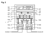
- Fig.2 shows the internal structure of a switching node (1-9) assuming that part of the logic may be executed in hardware, other in programmable logic and other by a processor under control of a stored program.
- a node consists of two communication ports (101a, 101b), one for each direction, with transceivers and decoding / encoding logic (102a, 102b) allowing to generate and check the frames contents and especially to detect that this frame was originally sent or already received, by inspecting the source address and other information in the frame.
- the decoding / encoding logic is connected to a switch element (103).
- the switch element (103) can transfer frames from port to port directly over two busses (103a, 103b) corresponding to the two direction of transfer on the ring, provided it is not the originator of the frame or did not already receive the same frame and is able to identify the frame as being properly formed.
- the switching element (103) is connected to the Link Redundancy Entity LRE (104).
- Source frames to be transmitted are received from non-ring devices (11a-11c) by switching intermediary node (9), or prepared by the upper protocol layers (106), such as the real-time publisher/subscriber stack (106') or the Internet Protocol (106") on which other protocols such as TCP or UDP are built, of a switching end node (1-6).
- the source frame (105') is passed over the link layer interface (105) to the LRE which has means (104') to duplicate this frame and to append the redundancy check information to it.
- the LRE For each such frame to send, the LRE generates two frames which switch element (103) sends on the ring, one in each direction A or B, as soon as the medium is available.
- the switch element In reception, the switch element passes both received frames to the LRE, which has means (104") to reject duplicates received from the ring and to pass only the first frame (105") of a pair to the upper protocols (106).
- the LRE discard can be done in interaction with a network controller or entirely in programmable logic.
- a sending node (50) operating according to the PRP protocol sends frame duplicates (50a, 50b) to two redundant or duplicated communication networks or lines designated as LAN A (40a) and LAN B (40b).
- the frames are forwarded to interlinks (33a, 33b) and received by coupling nodes (30a, 30b).
- the coupling node on LAN A (30a) only inserts the received frame into the ring, via a first communication port (A) and in a first ring communication direction (34a), while coupling node on LAN B (30b) inserts the frame in the opposite direction into the ring (34b).
- Both frames are forwarded over the ring by the switching nodes (1, 3) and arrive with a certain delay to the destination node (2), which processes the first frame of a pair and discards the duplicate.
- the frame (34a) sent by coupling node (30a) reaches that coupling node again, it is discarded since the coupling node (30a) registers the source of all frames it sends on behalf of LAN A and thus identifies the frame as sent by itself.
- the coupling node on LAN A (30a) relays frames originating from a node (1-3) of the ring network, either to the LAN A if received over its second port (B) as a frame circulating in the first ring communication direction, or to the second port (B) if received over the first port (A) as a frame circulating in the opposite direction.
- More than one ring can be connected to the duplicated network, by means of additional interlinks (63a, 63b) and corresponding coupling devices.
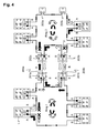
- Fig.4 shows essential components of a coupling between peer ring networks.
- two pairs of coupling nodes (201a, 201b; 202a, 202b) are used to connect two rings.
- Each coupling node is operating essentially as described in connection with Fig.3 , inserting frames only in one ring communication direction and forwarding to the link redundancy entity only frames that were received at the other port and circulating with the same ring communication direction.
- Further peer rings can be connected by further pairs of coupling nodes (203a, 203b).
Landscapes
- Engineering & Computer Science (AREA)
- Computer Networks & Wireless Communication (AREA)
- Signal Processing (AREA)
- Small-Scale Networks (AREA)
Abstract
The present invention applies to highly available automation networks arranged in a ring topology connecting critical devices that require seamless communication in case of link or device failure. The network coupling device is connected over a respective first and second port in a communication network with a ring topology operating with full duplex links, and inserts, when sending, in the ring two duplicate frames, one over each of its ports, said frames containing information allowing to identify these two frames as being duplicates of a pair. Each similar device in the ring comprises a Switching Element able to receive a frame from one port and to forward it to the other port without modification, with the exception that the switching Element discards a frame that was originally sent by that same node and/or discards a frame already received from that direction, and/or discards a frame that it cannot recognize as being a member of a pair. A further similar device on the ring is able to receive the two duplicate frames and to pass the earlier of a pair to the application, while discarding the later, based on the identification within the frames.
Description
- The invention relates to the field of industrial communication systems using redundant communication networks for controlling time-critical processes, in particular to vehicle control, drive control or substation automation.
- In industrial communication systems for time-critical applications such as vehicle control, drive control or substation automation, availability and reliability are key issues, because a failing communication system may lead to an interruption of the application and to a shutdown of an industrial plant controlled by the latter. Therefore, communication network redundancy is an important feature of industrial communication systems demanding high availability, in particular those using Ethernet-based communication with commercial switches.
- A key factor of a redundant system is the recovery delay in case of failure. Time-critical processes require short recovery delays in the order of milliseconds or, preferably, even a seamless recovery invisible to the plant, since too long an interruption of service can trigger a plant shutdown.
- A high level of redundancy with seamless operation in case of failure may be provided by duplicating the communication lines, e.g. the electrical or optical transmission cable, as well as at least the physical layer of the corresponding protocol stack of the devices attached to each of the two local area networks through two independent transceivers and bus controllers. For each frame to send, a sender sends two frames nearly simultaneously over both lines and the receiver accepts whichever frame of a pair of redundant frames comes first and discards the later frame. Switchover is seamless, since there is no need to repeat a frame in case of disruption of one path. The tagging of redundant frames offers a complete supervision of both redundant lines with normal traffic, ensuring a high coverage. This method has been described in patent application
WO 2006/053459 and standardized as Parallel Redundancy Protocol (PRP) in IEC standard 62439. However, the PRP requires a complete and hence rather uneconomical duplication of the physical network. - A ring topology provides a more cost-effective solution, especially when the switching element is integrated within the node (forming a switching end node), offering a similar availability as PRP but often suffering from long recovery delays. In a ring network, every node has two communication ports connecting to two neighbour nodes hence the ring network can be operated in either or both directions and thus offers resiliency against link failure. Ring networks such as FDDI or Token Ring are state-of-the art and can be of the Ethernet type, in which case protocols such as RSTP (IEEE 802.1D) ensure that frames cannot circulate indefinitely on the ring.
WO 2004/056049 discloses a substation-specific ring network normally operated in a first communication direction along a so-called primary ring. In the event of a fault on the primary ring, a part of the latter may be shortcircuited by a part of a secondary ring. - Nodes belonging to the ring are required to have two network interfaces, a property not shared by commercial off-the-shelf devices such as printers, loggers or laptop computers. These devices need to be attached to a switch, which in turn is connected as a point-to-point link to a switching (end) node of the ring. The switch and the switching end node can be integrated into the same device. Since each switching node introduces a forwarding delay, the number of devices in ring networks is generally limited and hierarchically structuring networks and/or coupling peer networks becomes advantageous.
- In all these state-of-the-art ring solutions, recovery bases on the redirection of the information flow on the still available links after detection of a failure. Such a restoration introduces a recovery delay that can be incompatible with the requirements of a higher level application.
- It is therefore an objective of the invention to reduce recovery delays in a ring type communication network and to prevent any failure of a network link from affecting higher level applications. These objectives are achieved by a switching node and a method of communicating between devices in different redundant communication networks according to the
claims - According to the invention, in a ring type communication network with a plurality of switching nodes and operating with full duplex links, a sender node transmits pairs of redundant frames. For each frame to be sent on the ring network, a source and a duplicate frame are transmitted in opposite directions, both frames being relayed by the other nodes of the ring network until they eventually return back to the originating sender node. As a consequence, network load is roughly doubled with respect to a conventional ring network. A destination node thus receives, in the fault-free state, two redundant frames with the same contents. It forwards only the earlier or first frame of the two frames to the upper layer protocols and discards the later or second frame.
- The redundant frames can be identified according to the Parallel Redundancy Protocol PRP, as disclosed e.g. in
WO 2006/053459 , by the sender node appending to each frame a sequence number, an identifier of a (counter-) clockwise relaying direction in the ring network, and a length field that allows recognizing duplicates in conjunction with the source address. - In an advantageous variant of the invention, to prevent frames from circulating indefinitely in the ring, the originating sender node does not relay a frame that it had previously sent itself. The latter is recognized based on the contents of the frame, especially based on the source address of the frame. A further preferred variant provides an additional safeguard against frames which are not, due to failure or untimely removal of the originating sender node, removed from the ring by the latter. In particular, each node may identify and discard frames that were already received. This mechanism is an extension of the PRP algorithm and is applied to each of the two relaying directions separately. An identifier of a (counter-) clockwise relaying direction in the ring network appended to each frame may assist in this distinction and define a separate Virtual Local Area Network for each of the two relaying directions.
- In a further preferred embodiment, non-ring devices are connected to the ring network by means of a switching intermediary node. The latter may comprise a third communication port linked to a single non-ring device or a switch which in turn connects to a plurality of non-ring devices. In this configuration, the intermediary node receives, doubles, and transmits source frames from a non-ring node without changing its source address, and by occasionally removing from the ring the source and duplicate frames that originate from non-ring nodes. To that purpose, the intermediary node keeps a Proxy or Interlink Node Table with suitable identifications or addresses of the non-ring devices that it acts on behalf of. Preferably, this table is kept up-to-date by removing entries corresponding to non-active non-ring devices after a time-out.
- According to another aspect of the invention, a pair of coupling nodes is used to couple a ring network to a duplicated PRP network, in which case one coupling node injects frames on the ring in one direction only, while the other coupling node injects frames in the opposite direction. In a final embodiment, two pairs of such coupling end nodes can be used to couple two peer rings, one pair acting in one direction of the ring while the other pair injects frames in the opposite direction.
- The present invention also relates to a computer program product including computer program code means executable on a processor of a switching node in a communication network of a process control system and storable on a computer readable medium such as a memory integrated in the node or a data carrier that can be inserted into the node.
- In summary, the present invention combines the seamless property of PRP and the low hardware costs of ring networks and provides for seamless recovery in a ring network. In addition, coupling highly available rings with a redundant network, and coupling two or more peer rings, becomes possible.
- The subject matter of the invention will be explained in more detail in the following text with reference to preferred exemplary embodiments which are illustrated in the attached drawings, of which
- Fig.1
- shows a state-of-the-art automation network in ring topology,
- Fig.2
- depicts some of the components and protocol layers of a switching end node,
- Fig.3
- shows a ring network coupled to a redundant network, and
- Fig.4
- shows a ring network coupled to a peer ring network.
- The reference symbols used in the drawings, and their meanings, are listed in summary form in the list of reference symbols. In principle, identical parts are provided with the same reference symbols in the figures.
-
Fig.1 depicts firstly a state-of-the-art automation network with a ring topology, in which all switching nodes within the ring (1 9), such as protection, control and measuring devices (1-4), supervision workstation (5), clock master (6), redundant telecontrol links (7, 8) as well as intermediary nodes (9) for non-ring devices (11a-11c) include a switch element (103) that is able to forwards frames (35a, 35b) from one port (101a, 101b) to the other, ensuring circulation of frames round the ring; The switch element of a sender node (1) can inject a frame passed to it from the higher protocol layers (106) through the link layer entity (105) in either or both directions (34a, 34b). The switch element of a destination node (4) is capable of receiving frames (36a, 36b) from either direction of the ring and to pass them to its own higher layer protocols. - While this general principle applies to most rings, which offer a variety of means for interrupting the ring (tokens, test frames, ..) in order to avoid permanently circulating frames, this invention discloses that a node always sends a frame received from its higher layer protocols over both its ports, that the two duplicates of the frame circulate over the bus in opposite direction until they reach their original sender, and that receivers pass only the earlier frame of a pair to their higher layer protocols and discard the duplicate.
-
Fig.2 shows the internal structure of a switching node (1-9) assuming that part of the logic may be executed in hardware, other in programmable logic and other by a processor under control of a stored program. A node consists of two communication ports (101a, 101b), one for each direction, with transceivers and decoding / encoding logic (102a, 102b) allowing to generate and check the frames contents and especially to detect that this frame was originally sent or already received, by inspecting the source address and other information in the frame. The decoding / encoding logic is connected to a switch element (103). - The switch element (103) can transfer frames from port to port directly over two busses (103a, 103b) corresponding to the two direction of transfer on the ring, provided it is not the originator of the frame or did not already receive the same frame and is able to identify the frame as being properly formed. The switching element (103) is connected to the Link Redundancy Entity LRE (104).
- Source frames to be transmitted are received from non-ring devices (11a-11c) by switching intermediary node (9), or prepared by the upper protocol layers (106), such as the real-time publisher/subscriber stack (106') or the Internet Protocol (106") on which other protocols such as TCP or UDP are built, of a switching end node (1-6). The source frame (105') is passed over the link layer interface (105) to the LRE which has means (104') to duplicate this frame and to append the redundancy check information to it. For each such frame to send, the LRE generates two frames which switch element (103) sends on the ring, one in each direction A or B, as soon as the medium is available.
- In reception, the switch element passes both received frames to the LRE, which has means (104") to reject duplicates received from the ring and to pass only the first frame (105") of a pair to the upper protocols (106). The LRE discard can be done in interaction with a network controller or entirely in programmable logic.
- In
Fig.3 , a sending node (50) operating according to the PRP protocol sends frame duplicates (50a, 50b) to two redundant or duplicated communication networks or lines designated as LAN A (40a) and LAN B (40b). The frames are forwarded to interlinks (33a, 33b) and received by coupling nodes (30a, 30b). The coupling node on LAN A (30a) only inserts the received frame into the ring, via a first communication port (A) and in a first ring communication direction (34a), while coupling node on LAN B (30b) inserts the frame in the opposite direction into the ring (34b). Both frames are forwarded over the ring by the switching nodes (1, 3) and arrive with a certain delay to the destination node (2), which processes the first frame of a pair and discards the duplicate. When the frame (34a) sent by coupling node (30a) reaches that coupling node again, it is discarded since the coupling node (30a) registers the source of all frames it sends on behalf of LAN A and thus identifies the frame as sent by itself. The coupling node on LAN A (30a) relays frames originating from a node (1-3) of the ring network, either to the LAN A if received over its second port (B) as a frame circulating in the first ring communication direction, or to the second port (B) if received over the first port (A) as a frame circulating in the opposite direction. - More than one ring can be connected to the duplicated network, by means of additional interlinks (63a, 63b) and corresponding coupling devices.
-
Fig.4 shows essential components of a coupling between peer ring networks. In this embodiment, two pairs of coupling nodes (201a, 201b; 202a, 202b) are used to connect two rings. Each coupling node is operating essentially as described in connection withFig.3 , inserting frames only in one ring communication direction and forwarding to the link redundancy entity only frames that were received at the other port and circulating with the same ring communication direction. - Further peer rings can be connected by further pairs of coupling nodes (203a, 203b).
-
- 1-9
- switching nodes
- 10
- switch to non-ring nodes
- 11a, 11b, 11c
- non-ring nodes
- 30a
- coupling node for direction A
- 30b
- coupling node for direction B
- 33a
- interlink connecting coupling node A to LAN A
- 33b
- interlink connecting coupling node B to LAN B
- 34a, 35a, 36a
- frame circulating in direction A
- 34b, 35b, 36b
- frame circulating in direction B
- 40a
- LAN A
- 40b
- LAN B
- 50
- PRP device
- 50a
- frame sent over one LAN A by a PRP device
- 50b
- frame sent over one LAN B by a PRP device
- 63a
- interlink to another ring in direction A
- 63b
- interlink to another ring in direction B
- 101a, 101b
- communication ports
- 102a, 102b
- decoding / encoding logic
- 103
- switch element
- 103a, 103b
- internal bus for transferring frames from one port to the other
- 104
- Link Redundancy Entity (LRE)
- 104'
- Frame duplicator (inserts the redundancy information)
- 104"
- Filter for discarding a duplicate frame
- 105
- Link Layer interface
- 105'
- Frame to send passed by the higher layers over the link layer interface
- 105"
- Frame received from the LRE to be passed to the higher layers
- 106
- Higher protocol layers
- 106"
- Publisher /Subscriber protocol on
level 2 - 106'
- IP protocol
- 200a
- Interlink A between
ring 1 andring 2 - 200b
- Interlink B between
ring 1 andring 2 - 201a
- coupling node in
ring 1 in direction A - 201b
- coupling node in
ring 1 in direction B - 202a
- coupling node in
ring 2 in direction A - 202b
- coupling node in
ring 2 in direction B - 203a
- coupling node in
ring 2 in direction B to a third ring - 203b
- coupling node in
ring 2 in direction B to a third ring
Claims (5)
- A switching node (1-9) with a first and second communication port (101a, 101b) to be connected to a first and second neighbouring node (1-9), respectively, of a communication network with a ring topology, the switching node being adapted to- generate a duplicate frame of a source frame (105') to be transmitted to a destination node (4) and to transmit, essentially simultaneously via the first and the second port, respectively, the source frame and the duplicate frame to the first and second neighbouring node,- relay unidentified frames from one port to the other, and- retain an earlier frame (105") of a pair comprising a source and a duplicate frame received from a sender node (1) via the first and the second port, respectively, and to reject a later frame of the pair.
- The switching node according to claim 1, characterized in that it is adapted to - eliminate any frame received and identified as a source or duplicate frame transmitted by the switching node itself.
- The switching node according to claim 1, characterized in that it is adapted to - eliminate a frame identified as having been received previously via the same port of the node.
- The switching node according to claim 1, characterized in that it is adapted to- receive a source frame from a non-ring device (11a-11c), and- store an identification of the non-ring device.
- A method of communicating between a first device (50) connected to two redundant communication networks (40a, 40b) and a second device (2) connected to a ring network as a switching node according to one of the preceding claims, wherein two coupling nodes (30a, 30b) are provided for coupling the two communication networks to the ring network, each coupling node comprising a first and second port to connect to a first and second neighbouring node of the ring network, respectively, and a third port to connect to either one of the communication networks, the method comprising -relaying, by the two coupling nodes, frames from the third port to the first port, and from the second port to the third port.
Priority Applications (7)
| Application Number | Priority Date | Filing Date | Title |
|---|---|---|---|
| EP08160883A EP2148473A1 (en) | 2008-07-22 | 2008-07-22 | Switching nodes for high availability networks |
| JP2011519161A JP2011528883A (en) | 2008-07-22 | 2009-07-22 | Ring coupling node in a network with high availability |
| PCT/EP2009/059426 WO2010010120A1 (en) | 2008-07-22 | 2009-07-22 | Ring coupling nodes for high availability networks |
| EP09780927A EP2327185A1 (en) | 2008-07-22 | 2009-07-22 | Ring coupling nodes for high availability networks |
| CN2009801294067A CN102106121A (en) | 2008-07-22 | 2009-07-22 | Ring coupling nodes for high availability networks |
| BRPI0916383A BRPI0916383A2 (en) | 2008-07-22 | 2009-07-22 | ring coupling nodes for high availability networks |
| US13/010,216 US8582424B2 (en) | 2008-07-22 | 2011-01-20 | Ring coupling nodes for high availability networks |
Applications Claiming Priority (1)
| Application Number | Priority Date | Filing Date | Title |
|---|---|---|---|
| EP08160883A EP2148473A1 (en) | 2008-07-22 | 2008-07-22 | Switching nodes for high availability networks |
Publications (1)
| Publication Number | Publication Date |
|---|---|
| EP2148473A1 true EP2148473A1 (en) | 2010-01-27 |
Family
ID=39745351
Family Applications (2)
| Application Number | Title | Priority Date | Filing Date |
|---|---|---|---|
| EP08160883A Withdrawn EP2148473A1 (en) | 2008-07-22 | 2008-07-22 | Switching nodes for high availability networks |
| EP09780927A Withdrawn EP2327185A1 (en) | 2008-07-22 | 2009-07-22 | Ring coupling nodes for high availability networks |
Family Applications After (1)
| Application Number | Title | Priority Date | Filing Date |
|---|---|---|---|
| EP09780927A Withdrawn EP2327185A1 (en) | 2008-07-22 | 2009-07-22 | Ring coupling nodes for high availability networks |
Country Status (6)
| Country | Link |
|---|---|
| US (1) | US8582424B2 (en) |
| EP (2) | EP2148473A1 (en) |
| JP (1) | JP2011528883A (en) |
| CN (1) | CN102106121A (en) |
| BR (1) | BRPI0916383A2 (en) |
| WO (1) | WO2010010120A1 (en) |
Cited By (16)
| Publication number | Priority date | Publication date | Assignee | Title |
|---|---|---|---|---|
| EP2395404A1 (en) | 2010-06-09 | 2011-12-14 | ABB Research Ltd. | Secure clock synchronization |
| EP2410697A1 (en) | 2010-07-20 | 2012-01-25 | ABB Research Ltd. | Frame transmission and communication network |
| WO2013075895A1 (en) * | 2011-11-21 | 2013-05-30 | Siemens Aktiengesellschaft | Method for redundant communication between a user terminal and a control system server |
| EP2608456A1 (en) * | 2011-12-21 | 2013-06-26 | ABB Technology AG | Substation automation system with dynamic multicast filter |
| WO2013143592A1 (en) * | 2012-03-29 | 2013-10-03 | Siemens Aktiengesellschaft | Method and apparatus for redundantly transmitting time-critical data |
| WO2014032736A1 (en) | 2012-09-03 | 2014-03-06 | Siemens Aktiengesellschaft | Interference-immune transmission of data telegrams in a communications network |
| WO2014095533A1 (en) * | 2012-12-21 | 2014-06-26 | Thales | Network for transmitting information with at least two loops |
| EP2924928A1 (en) | 2014-03-25 | 2015-09-30 | Siemens Aktiengesellschaft | Receiver network component for operation in a communication network, communication network and method for operation of a communication network |
| DE102016110150A1 (en) * | 2016-06-01 | 2017-12-07 | Airbus Defence and Space GmbH | HYBRID NETWORK ENDSYSTEMEINRICHTUNG |
| CN108351894A (en) * | 2015-11-12 | 2018-07-31 | 微软技术许可有限责任公司 | File system with distributed entities state |
| EP3155763B1 (en) * | 2014-07-29 | 2018-12-05 | Siemens Aktiengesellschaft | Redundant transmission of data telegrams in communication networks having ring topology |
| EP3422641A1 (en) * | 2017-06-30 | 2019-01-02 | Siemens Aktiengesellschaft | Method for message delivery in a redundant operable industrial communication network and communication device for carrying out said method |
| EP3469769A4 (en) * | 2016-06-10 | 2019-12-25 | Tttech Flexibilis Oy | Receiving frames at redundant port connecting node to communications network |
| EP3477907A4 (en) * | 2016-07-12 | 2020-03-04 | Korea Electrotechnology Research Institute | Communication device for duplication network and data processing method thereof |
| EP4054143A1 (en) | 2021-03-02 | 2022-09-07 | Siemens Aktiengesellschaft | Authentification of a device in a communication network of an automation system |
| EP4060946A1 (en) | 2021-03-16 | 2022-09-21 | Siemens Aktiengesellschaft | Authentification of a device in a communication network of an automation system |
Families Citing this family (30)
| Publication number | Priority date | Publication date | Assignee | Title |
|---|---|---|---|---|
| EP2566111A1 (en) | 2011-08-30 | 2013-03-06 | ABB Technology AG | Utility communication method and system |
| DE102012000188B4 (en) * | 2012-01-09 | 2015-05-28 | Siemens Aktiengesellschaft | Method for operating a communication network and network arrangement |
| DE102012000185B4 (en) * | 2012-01-09 | 2014-11-06 | Siemens Aktiengesellschaft | Method for operating a communication network and network arrangement |
| DE102012002494A1 (en) * | 2012-02-10 | 2013-08-14 | Phoenix Contact Gmbh & Co. Kg | Alternative synchronization connections between redundant controllers |
| KR101328355B1 (en) * | 2012-02-17 | 2013-11-11 | 명지대학교 산학협력단 | Method of reducing traffic of a network |
| EP2634973B1 (en) | 2012-02-29 | 2014-10-01 | Siemens Aktiengesellschaft | Communication device for a redundant industrial communication network and method for operating a communication device |
| CN103428060A (en) * | 2012-05-25 | 2013-12-04 | 北京东土科技股份有限公司 | Seamless redundancy realization method of loop network |
| DE102012209108B4 (en) * | 2012-05-30 | 2014-05-15 | Siemens Aktiengesellschaft | Network device, network device and method for operating a network device |
| EP2712124B1 (en) * | 2012-09-24 | 2015-04-01 | Siemens Aktiengesellschaft | Redundant industrial communication system and method for its operation |
| FR3002393B1 (en) * | 2013-02-15 | 2016-06-24 | Thales Sa | INFORMATION TRANSMISSION ARCHITECTURE, IN PARTICULAR FOR APPLICATION TO AIRCRAFT AVIONICS |
| FR3002394B1 (en) | 2013-02-15 | 2015-03-27 | Thales Sa | ARCHITECTURE FOR TRANSMITTING INFORMATION WITH A BRIDGE, IN PARTICULAR FOR APPLICATION TO THE AIRCRAFT |
| US9817784B2 (en) * | 2013-03-22 | 2017-11-14 | Nxp Usa, Inc. | Multi-port transmitter device for transmitting at least partly redundant data, an associated control system, an associated method and an associated computer program product |
| EP2887593B1 (en) * | 2013-12-20 | 2019-10-09 | ABB Schweiz AG | Network interface for transmitting protection data of a power network |
| EP2882169B1 (en) * | 2014-08-19 | 2017-10-04 | ABB Schweiz AG | Redundant content bridging between substation communication networks |
| CN104158687B (en) * | 2014-08-21 | 2017-11-10 | 国电南瑞科技股份有限公司 | The device and implementation method of double-network redundant in a kind of transformer station |
| DE102016110315A1 (en) * | 2015-06-03 | 2016-12-08 | Hirschmann Automation And Control Gmbh | Method for a redundant transmission system with PRP and buffering of data packets |
| DE102015010969A1 (en) | 2015-08-26 | 2017-03-02 | Airbus Defence and Space GmbH | Network module for sending and / or receiving data packets from a network device and method |
| DE102016110148A1 (en) * | 2016-06-01 | 2017-12-07 | Airbus Defence and Space GmbH | End system device with integrated switching device |
| US20180048487A1 (en) * | 2016-08-15 | 2018-02-15 | Alcatel-Lucent Canada Inc. | Method for handling network partition in cloud computing |
| WO2018206560A1 (en) | 2017-05-08 | 2018-11-15 | Abb Schweiz Ag | Multiple fed busbar system |
| CN109561023B (en) | 2017-09-27 | 2022-03-11 | 华为技术有限公司 | Method, device and system for transmitting multicast message |
| US11025537B2 (en) * | 2017-12-04 | 2021-06-01 | Is5 Communications, Inc. | Multiple RSTP domain separation |
| CN108156023B (en) * | 2017-12-11 | 2021-01-05 | 西安电子科技大学 | Time sensitivity network analysis system and method based on redundancy mechanism |
| DE102017130386A1 (en) * | 2017-12-18 | 2019-06-19 | Northrop Grumman Litef Gmbh | Vehicle with fail-safe internal data transmission |
| EP3629550A1 (en) * | 2018-09-27 | 2020-04-01 | Siemens Aktiengesellschaft | Method for transmitting data within an industrial communication system and coupling communication device |
| KR102262385B1 (en) * | 2019-10-15 | 2021-06-08 | 한국전력공사 | Highly Reliable, Low Cost Next Generation Network System For Digital Substation |
| US11743111B2 (en) | 2019-11-11 | 2023-08-29 | Siemens Canada Limited | Network device and a method of configuring the network device therefor |
| CN112887182A (en) * | 2019-11-29 | 2021-06-01 | 华为技术有限公司 | Data transmission method, equipment and system |
| US11265208B1 (en) * | 2020-12-29 | 2022-03-01 | Honeywell International Inc. | Detecting path faults in parallel redundancy protocol communications |
| US11831467B1 (en) * | 2022-05-13 | 2023-11-28 | International Business Machines Corporation | Programmable multicast protocol for ring-topology based artificial intelligence systems |
Citations (19)
| Publication number | Priority date | Publication date | Assignee | Title |
|---|---|---|---|---|
| US5781545A (en) * | 1996-05-22 | 1998-07-14 | Harris Corporation | Packet source exclusion method |
| WO2000013376A1 (en) * | 1998-08-28 | 2000-03-09 | Integral Access, Inc. | Redundant path data communication |
| US20010018328A1 (en) * | 2000-02-29 | 2001-08-30 | Yoshinori Ohkura | Radio relay system |
| US20020027877A1 (en) * | 2000-09-02 | 2002-03-07 | Agency For Defense Development | Packet processing method using multiple fault tolerant network structure |
| US20020075873A1 (en) * | 2000-12-20 | 2002-06-20 | Gwenda Lindhorst-Ko | Method of protecting traffic in a mesh network |
| EP1231541A2 (en) * | 2001-02-05 | 2002-08-14 | Nec Corporation | Computer system and method of communication between modules within computer system |
| US20030048782A1 (en) * | 2000-12-22 | 2003-03-13 | Rogers Steven A. | Generation of redundant scheduled network paths using a branch and merge technique |
| US20040008719A1 (en) * | 2002-07-10 | 2004-01-15 | I/O Controls Corporation | Fiber optic control network and related method |
| US6751746B1 (en) * | 2000-07-31 | 2004-06-15 | Cisco Technology, Inc. | Method and apparatus for uninterrupted packet transfer using replication over disjoint paths |
| WO2004056049A1 (en) | 2002-12-13 | 2004-07-01 | Areva T & D Sa | Dual-ring ethernet network |
| WO2004059921A1 (en) * | 2002-12-31 | 2004-07-15 | Nokia Corporation | Method and system for detecting duplicated frames in a mirrored network |
| US20040199662A1 (en) * | 2003-04-02 | 2004-10-07 | Karol Mark J. | System and method to improve the resiliency and performance of enterprise networks by utilizing in-built network redundancy |
| US6831898B1 (en) * | 2000-08-16 | 2004-12-14 | Cisco Systems, Inc. | Multiple packet paths to improve reliability in an IP network |
| EP1657888A1 (en) * | 2004-11-16 | 2006-05-17 | Abb Research Ltd. | Reception of redundant and non-redundant frames |
| EP1768328A1 (en) * | 2004-07-14 | 2007-03-28 | Nippon Telegraph and Telephone Corporation | Packet transmission method and packet transmission device |
| WO2007040417A1 (en) * | 2005-10-03 | 2007-04-12 | Motorola, Inc. | Method and apparatus for communicating a message in a mesh network |
| FR2893205A1 (en) * | 2005-11-09 | 2007-05-11 | Hardtech Sarl | Communication network managing method, involves introducing data frames on network using introducing repeater which introduces frames by emitting two specimens of frames on loops in parallel manner |
| US20070274229A1 (en) * | 2006-05-24 | 2007-11-29 | Sbc Knowledge Ventures, L.P. | Method and apparatus for reliable communications in a packet network |
| US20080059651A1 (en) * | 2006-08-30 | 2008-03-06 | Nortel Networks Limited | Distribution of XML documents/messages to XML appliances/routers |
Family Cites Families (15)
| Publication number | Priority date | Publication date | Assignee | Title |
|---|---|---|---|---|
| JP3102471B2 (en) * | 1997-01-31 | 2000-10-23 | 日本電気株式会社 | Signal switching method |
| US6466574B1 (en) * | 1998-06-05 | 2002-10-15 | International Business Machines Corporation | Quality of service improvement of internet real-time media transmission by transmitting redundant voice/media frames |
| JP2001007846A (en) * | 1999-06-18 | 2001-01-12 | Fujitsu Ltd | Frame repeater |
| JP2001053753A (en) * | 1999-08-09 | 2001-02-23 | Fujitsu Ltd | Method for switching active/reserve line and atm exchange using the same |
| US6990066B1 (en) * | 1999-10-06 | 2006-01-24 | Cisco Technology, Inc. | Method for using a pre-configured ATM switch and traffic discard to facilitate UPSR selection |
| US7035208B1 (en) * | 1999-11-30 | 2006-04-25 | Lucent Technologies Inc. | Reverse statistical multiplexing to achieve efficient digital packing with link protection |
| US6891828B2 (en) * | 2001-03-12 | 2005-05-10 | Network Excellence For Enterprises Corp. | Dual-loop bus-based network switch using distance-value or bit-mask |
| JP2003174479A (en) * | 2001-12-07 | 2003-06-20 | Fujitsu Ltd | Packet communication method and device therefor |
| EP1530842A4 (en) * | 2002-07-10 | 2008-03-19 | I O Controls Corp | Fiber optic control network and related method |
| US7046621B2 (en) * | 2002-07-10 | 2006-05-16 | I/O Controls Corporation | Redundant multi-fiber optical ring network |
| JP4074268B2 (en) * | 2003-08-22 | 2008-04-09 | 日本電信電話株式会社 | Packet transfer method and transfer device |
| US7653066B2 (en) * | 2004-11-04 | 2010-01-26 | Cisco Technology Inc. | Method and apparatus for guaranteed in-order delivery for FICON over SONET/SDH transport |
| US7120360B2 (en) * | 2005-01-06 | 2006-10-10 | Fujitsu Limited | System and method for protecting traffic in a hubbed optical ring network |
| WO2006129701A1 (en) * | 2005-05-31 | 2006-12-07 | Nec Corporation | Packet ring network system, packet transfer method, and node |
| US7748034B2 (en) * | 2005-10-12 | 2010-06-29 | Cisco Technology, Inc. | Strong anti-replay protection for IP traffic sent point to point or multi-cast to large groups |
-
2008
- 2008-07-22 EP EP08160883A patent/EP2148473A1/en not_active Withdrawn
-
2009
- 2009-07-22 BR BRPI0916383A patent/BRPI0916383A2/en not_active IP Right Cessation
- 2009-07-22 WO PCT/EP2009/059426 patent/WO2010010120A1/en active Application Filing
- 2009-07-22 EP EP09780927A patent/EP2327185A1/en not_active Withdrawn
- 2009-07-22 CN CN2009801294067A patent/CN102106121A/en active Pending
- 2009-07-22 JP JP2011519161A patent/JP2011528883A/en active Pending
-
2011
- 2011-01-20 US US13/010,216 patent/US8582424B2/en active Active
Patent Citations (20)
| Publication number | Priority date | Publication date | Assignee | Title |
|---|---|---|---|---|
| US5781545A (en) * | 1996-05-22 | 1998-07-14 | Harris Corporation | Packet source exclusion method |
| WO2000013376A1 (en) * | 1998-08-28 | 2000-03-09 | Integral Access, Inc. | Redundant path data communication |
| US20010018328A1 (en) * | 2000-02-29 | 2001-08-30 | Yoshinori Ohkura | Radio relay system |
| US6751746B1 (en) * | 2000-07-31 | 2004-06-15 | Cisco Technology, Inc. | Method and apparatus for uninterrupted packet transfer using replication over disjoint paths |
| US6831898B1 (en) * | 2000-08-16 | 2004-12-14 | Cisco Systems, Inc. | Multiple packet paths to improve reliability in an IP network |
| US20020027877A1 (en) * | 2000-09-02 | 2002-03-07 | Agency For Defense Development | Packet processing method using multiple fault tolerant network structure |
| US20020075873A1 (en) * | 2000-12-20 | 2002-06-20 | Gwenda Lindhorst-Ko | Method of protecting traffic in a mesh network |
| US20030048782A1 (en) * | 2000-12-22 | 2003-03-13 | Rogers Steven A. | Generation of redundant scheduled network paths using a branch and merge technique |
| EP1231541A2 (en) * | 2001-02-05 | 2002-08-14 | Nec Corporation | Computer system and method of communication between modules within computer system |
| US20040008719A1 (en) * | 2002-07-10 | 2004-01-15 | I/O Controls Corporation | Fiber optic control network and related method |
| WO2004056049A1 (en) | 2002-12-13 | 2004-07-01 | Areva T & D Sa | Dual-ring ethernet network |
| WO2004059921A1 (en) * | 2002-12-31 | 2004-07-15 | Nokia Corporation | Method and system for detecting duplicated frames in a mirrored network |
| US20040199662A1 (en) * | 2003-04-02 | 2004-10-07 | Karol Mark J. | System and method to improve the resiliency and performance of enterprise networks by utilizing in-built network redundancy |
| EP1768328A1 (en) * | 2004-07-14 | 2007-03-28 | Nippon Telegraph and Telephone Corporation | Packet transmission method and packet transmission device |
| EP1657888A1 (en) * | 2004-11-16 | 2006-05-17 | Abb Research Ltd. | Reception of redundant and non-redundant frames |
| WO2006053459A1 (en) | 2004-11-16 | 2006-05-26 | Abb Research Ltd | Reception of redundant and non-redundant frames |
| WO2007040417A1 (en) * | 2005-10-03 | 2007-04-12 | Motorola, Inc. | Method and apparatus for communicating a message in a mesh network |
| FR2893205A1 (en) * | 2005-11-09 | 2007-05-11 | Hardtech Sarl | Communication network managing method, involves introducing data frames on network using introducing repeater which introduces frames by emitting two specimens of frames on loops in parallel manner |
| US20070274229A1 (en) * | 2006-05-24 | 2007-11-29 | Sbc Knowledge Ventures, L.P. | Method and apparatus for reliable communications in a packet network |
| US20080059651A1 (en) * | 2006-08-30 | 2008-03-06 | Nortel Networks Limited | Distribution of XML documents/messages to XML appliances/routers |
Cited By (34)
| Publication number | Priority date | Publication date | Assignee | Title |
|---|---|---|---|---|
| RU2487382C1 (en) * | 2010-06-09 | 2013-07-10 | Абб Рисерч Лтд | Protected clock synchronisation |
| WO2011154217A1 (en) | 2010-06-09 | 2011-12-15 | Abb Research Ltd | Secure clock synchronization |
| US9363273B2 (en) | 2010-06-09 | 2016-06-07 | Abb Research Ltd. | Secure clock synchronization |
| US10148411B2 (en) | 2010-06-09 | 2018-12-04 | Abb Research Ltd | Secure clock synchronization |
| EP2395404A1 (en) | 2010-06-09 | 2011-12-14 | ABB Research Ltd. | Secure clock synchronization |
| WO2012010619A1 (en) | 2010-07-20 | 2012-01-26 | Abb Research Ltd | Frame transmission and communication network |
| US9106595B2 (en) | 2010-07-20 | 2015-08-11 | Abb Research Ltd | Frame transmission and communication network |
| EP2410697A1 (en) | 2010-07-20 | 2012-01-25 | ABB Research Ltd. | Frame transmission and communication network |
| RU2534931C2 (en) * | 2010-07-20 | 2014-12-10 | Абб Рисерч Лтд | Data block transmission and communication network |
| WO2013075895A1 (en) * | 2011-11-21 | 2013-05-30 | Siemens Aktiengesellschaft | Method for redundant communication between a user terminal and a control system server |
| WO2013092439A1 (en) * | 2011-12-21 | 2013-06-27 | Abb Technology Ag | Substation automation system with dynamic multicast filter |
| EP2608456A1 (en) * | 2011-12-21 | 2013-06-26 | ABB Technology AG | Substation automation system with dynamic multicast filter |
| US9696696B2 (en) | 2011-12-21 | 2017-07-04 | Abb Schweiz Ag | Substation automation system with dynamic multicast filter |
| WO2013143592A1 (en) * | 2012-03-29 | 2013-10-03 | Siemens Aktiengesellschaft | Method and apparatus for redundantly transmitting time-critical data |
| US9871747B2 (en) | 2012-09-03 | 2018-01-16 | Siemens Aktiengesellschaft | Interference-immune transmission of data messages in a communications network |
| WO2014032736A1 (en) | 2012-09-03 | 2014-03-06 | Siemens Aktiengesellschaft | Interference-immune transmission of data telegrams in a communications network |
| US9774472B2 (en) | 2012-12-21 | 2017-09-26 | Thales | Network for transmitting information with at least two loops |
| WO2014095533A1 (en) * | 2012-12-21 | 2014-06-26 | Thales | Network for transmitting information with at least two loops |
| FR3000338A1 (en) * | 2012-12-21 | 2014-06-27 | Thales Sa | INFORMATION TRANSMISSION NETWORK HAVING AT LEAST TWO BUCKLES |
| EP2924928A1 (en) | 2014-03-25 | 2015-09-30 | Siemens Aktiengesellschaft | Receiver network component for operation in a communication network, communication network and method for operation of a communication network |
| US9832254B2 (en) | 2014-03-25 | 2017-11-28 | Siemens Aktiengesellschaft | Receiver network component for operation in a communication network, communication network and method for operating a communication network |
| EP3155763B1 (en) * | 2014-07-29 | 2018-12-05 | Siemens Aktiengesellschaft | Redundant transmission of data telegrams in communication networks having ring topology |
| US10182015B2 (en) | 2014-07-29 | 2019-01-15 | Siemens Aktiengesellschaft | Redundant transmission of data frames in communication networks having a ring topology |
| CN108351894A (en) * | 2015-11-12 | 2018-07-31 | 微软技术许可有限责任公司 | File system with distributed entities state |
| CN108351894B (en) * | 2015-11-12 | 2022-06-17 | 微软技术许可有限责任公司 | File system with distributed entity states |
| DE102016110150A1 (en) * | 2016-06-01 | 2017-12-07 | Airbus Defence and Space GmbH | HYBRID NETWORK ENDSYSTEMEINRICHTUNG |
| US10277419B2 (en) | 2016-06-01 | 2019-04-30 | Airbus Defence & Space Gmbh | Hybrid network end system device |
| US11283556B2 (en) | 2016-06-10 | 2022-03-22 | Tttech Flexibilis Oy | Receiving frames at redundant port connecting node to communications network |
| EP3469769A4 (en) * | 2016-06-10 | 2019-12-25 | Tttech Flexibilis Oy | Receiving frames at redundant port connecting node to communications network |
| EP3477907A4 (en) * | 2016-07-12 | 2020-03-04 | Korea Electrotechnology Research Institute | Communication device for duplication network and data processing method thereof |
| WO2019001828A1 (en) * | 2017-06-30 | 2019-01-03 | Siemens Aktiengesellschaft | Method for message transmission in a redundantly operable industrial communications network and communications device for the implementation thereof |
| EP3422641A1 (en) * | 2017-06-30 | 2019-01-02 | Siemens Aktiengesellschaft | Method for message delivery in a redundant operable industrial communication network and communication device for carrying out said method |
| EP4054143A1 (en) | 2021-03-02 | 2022-09-07 | Siemens Aktiengesellschaft | Authentification of a device in a communication network of an automation system |
| EP4060946A1 (en) | 2021-03-16 | 2022-09-21 | Siemens Aktiengesellschaft | Authentification of a device in a communication network of an automation system |
Also Published As
| Publication number | Publication date |
|---|---|
| US8582424B2 (en) | 2013-11-12 |
| JP2011528883A (en) | 2011-11-24 |
| BRPI0916383A2 (en) | 2018-02-06 |
| EP2327185A1 (en) | 2011-06-01 |
| WO2010010120A1 (en) | 2010-01-28 |
| US20110116508A1 (en) | 2011-05-19 |
| CN102106121A (en) | 2011-06-22 |
Similar Documents
| Publication | Publication Date | Title |
|---|---|---|
| EP2148473A1 (en) | Switching nodes for high availability networks | |
| JP5021037B2 (en) | Communication system having master / slave structure | |
| EP2282452B1 (en) | Data transmission in a ring-type communication network | |
| CA2323429C (en) | Local network, particularly an ethernet network, with redundancy properties, as well as a redundancy manager | |
| US9673995B2 (en) | Communication device and method for redundant message transmission in an industrial communication network | |
| US6963932B2 (en) | Intermediate driver having a fail-over function for a virtual network interface card in a system utilizing Infiniband architecture | |
| US9413609B2 (en) | Communication device and method for transmitting messages in a redundantly operable industrial communication network | |
| JP4790591B2 (en) | Ring node device | |
| EP3599521B1 (en) | System and method of communicating data over high availability industrial control systems | |
| CN111886834B (en) | System, method and apparatus for inter-segment communication | |
| US8184650B2 (en) | Filtering of redundant frames in a network node | |
| JP4705492B2 (en) | Ring node device and ring node redundancy method | |
| US8687523B2 (en) | System and method for integrating ring-protocol-compatible devices into network configurations that also include non-ring-protocol compatible devices | |
| US20090103554A1 (en) | Data transfer device for ring protocol high speed switching and method for the same | |
| JP3888866B2 (en) | Ethernet transmission line redundancy system | |
| CN116530058B (en) | Automation system with master-slave structure, distributor and telegram transmission method | |
| CN113037622B (en) | System and method for preventing BFD from vibrating | |
| CN102739430A (en) | Method and system for realizing Ethernet protection switching | |
| KR102602597B1 (en) | Method for Switchover of Communication Line in Ring Network using Dual Communication | |
| JP2006148761A (en) | Network system | |
| JP2000244505A (en) | Packet communication network system and its control method | |
| JP2002064551A (en) | Packet transfer device | |
| JP2010081364A (en) | Repeater and transmitting/receiving system |
Legal Events
| Date | Code | Title | Description |
|---|---|---|---|
| PUAI | Public reference made under article 153(3) epc to a published international application that has entered the european phase |
Free format text: ORIGINAL CODE: 0009012 |
|
| AK | Designated contracting states |
Kind code of ref document: A1 Designated state(s): AT BE BG CH CY CZ DE DK EE ES FI FR GB GR HR HU IE IS IT LI LT LU LV MC MT NL NO PL PT RO SE SI SK TR |
|
| AX | Request for extension of the european patent |
Extension state: AL BA MK RS |
|
| AKY | No designation fees paid | ||
| REG | Reference to a national code |
Ref country code: DE Ref legal event code: 8566 |
|
| STAA | Information on the status of an ep patent application or granted ep patent |
Free format text: STATUS: THE APPLICATION IS DEEMED TO BE WITHDRAWN |
|
| 18D | Application deemed to be withdrawn |
Effective date: 20100728 |