EP2148376A2 - Method and device for switching solar cells in a photovoltaic module - Google Patents
Method and device for switching solar cells in a photovoltaic module Download PDFInfo
- Publication number
- EP2148376A2 EP2148376A2 EP20090009354 EP09009354A EP2148376A2 EP 2148376 A2 EP2148376 A2 EP 2148376A2 EP 20090009354 EP20090009354 EP 20090009354 EP 09009354 A EP09009354 A EP 09009354A EP 2148376 A2 EP2148376 A2 EP 2148376A2
- Authority
- EP
- European Patent Office
- Prior art keywords
- contact strip
- heating
- contact
- solar cells
- conductive adhesive
- Prior art date
- Legal status (The legal status is an assumption and is not a legal conclusion. Google has not performed a legal analysis and makes no representation as to the accuracy of the status listed.)
- Withdrawn
Links
- 238000000034 method Methods 0.000 title claims abstract description 33
- 238000010438 heat treatment Methods 0.000 claims abstract description 74
- 230000001070 adhesive effect Effects 0.000 claims abstract description 46
- 239000000853 adhesive Substances 0.000 claims abstract description 45
- 229920003023 plastic Polymers 0.000 claims abstract description 8
- 239000004033 plastic Substances 0.000 claims abstract description 5
- 239000000463 material Substances 0.000 claims description 3
- 230000003213 activating effect Effects 0.000 claims 1
- 230000001276 controlling effect Effects 0.000 claims 1
- 238000012544 monitoring process Methods 0.000 claims 1
- 230000001105 regulatory effect Effects 0.000 claims 1
- 230000004913 activation Effects 0.000 abstract description 5
- 239000011521 glass Substances 0.000 description 14
- 238000003475 lamination Methods 0.000 description 5
- 238000004519 manufacturing process Methods 0.000 description 5
- 238000004132 cross linking Methods 0.000 description 4
- 239000010409 thin film Substances 0.000 description 4
- 239000012790 adhesive layer Substances 0.000 description 3
- 238000011109 contamination Methods 0.000 description 3
- 239000007789 gas Substances 0.000 description 3
- 239000010410 layer Substances 0.000 description 3
- 238000012545 processing Methods 0.000 description 3
- 229910000639 Spring steel Inorganic materials 0.000 description 2
- 239000002390 adhesive tape Substances 0.000 description 2
- 239000002131 composite material Substances 0.000 description 2
- 238000010292 electrical insulation Methods 0.000 description 2
- 238000001465 metallisation Methods 0.000 description 2
- 230000008646 thermal stress Effects 0.000 description 2
- RYGMFSIKBFXOCR-UHFFFAOYSA-N Copper Chemical compound [Cu] RYGMFSIKBFXOCR-UHFFFAOYSA-N 0.000 description 1
- 239000004696 Poly ether ether ketone Substances 0.000 description 1
- JUPQTSLXMOCDHR-UHFFFAOYSA-N benzene-1,4-diol;bis(4-fluorophenyl)methanone Chemical compound OC1=CC=C(O)C=C1.C1=CC(F)=CC=C1C(=O)C1=CC=C(F)C=C1 JUPQTSLXMOCDHR-UHFFFAOYSA-N 0.000 description 1
- 230000015572 biosynthetic process Effects 0.000 description 1
- DQXBYHZEEUGOBF-UHFFFAOYSA-N but-3-enoic acid;ethene Chemical compound C=C.OC(=O)CC=C DQXBYHZEEUGOBF-UHFFFAOYSA-N 0.000 description 1
- 238000004140 cleaning Methods 0.000 description 1
- 238000001816 cooling Methods 0.000 description 1
- 229910052802 copper Inorganic materials 0.000 description 1
- 239000010949 copper Substances 0.000 description 1
- 230000006735 deficit Effects 0.000 description 1
- 238000013461 design Methods 0.000 description 1
- 238000011161 development Methods 0.000 description 1
- 230000018109 developmental process Effects 0.000 description 1
- 238000010586 diagram Methods 0.000 description 1
- 230000000694 effects Effects 0.000 description 1
- 238000005265 energy consumption Methods 0.000 description 1
- 239000005038 ethylene vinyl acetate Substances 0.000 description 1
- 230000005284 excitation Effects 0.000 description 1
- 238000002474 experimental method Methods 0.000 description 1
- 239000012530 fluid Substances 0.000 description 1
- 239000003779 heat-resistant material Substances 0.000 description 1
- 239000012535 impurity Substances 0.000 description 1
- 230000002045 lasting effect Effects 0.000 description 1
- 238000001208 nuclear magnetic resonance pulse sequence Methods 0.000 description 1
- 235000011837 pasties Nutrition 0.000 description 1
- 229920001200 poly(ethylene-vinyl acetate) Polymers 0.000 description 1
- 229920002530 polyetherether ketone Polymers 0.000 description 1
- 229920000642 polymer Polymers 0.000 description 1
- 239000004810 polytetrafluoroethylene Substances 0.000 description 1
- 229920001343 polytetrafluoroethylene Polymers 0.000 description 1
- 230000000284 resting effect Effects 0.000 description 1
- 239000004065 semiconductor Substances 0.000 description 1
- 230000035939 shock Effects 0.000 description 1
- 230000035882 stress Effects 0.000 description 1
- 239000000758 substrate Substances 0.000 description 1
Images

Classifications
-
- H—ELECTRICITY
- H01—ELECTRIC ELEMENTS
- H01L—SEMICONDUCTOR DEVICES NOT COVERED BY CLASS H10
- H01L31/00—Semiconductor devices sensitive to infrared radiation, light, electromagnetic radiation of shorter wavelength or corpuscular radiation and specially adapted either for the conversion of the energy of such radiation into electrical energy or for the control of electrical energy by such radiation; Processes or apparatus specially adapted for the manufacture or treatment thereof or of parts thereof; Details thereof
- H01L31/04—Semiconductor devices sensitive to infrared radiation, light, electromagnetic radiation of shorter wavelength or corpuscular radiation and specially adapted either for the conversion of the energy of such radiation into electrical energy or for the control of electrical energy by such radiation; Processes or apparatus specially adapted for the manufacture or treatment thereof or of parts thereof; Details thereof adapted as photovoltaic [PV] conversion devices
- H01L31/042—PV modules or arrays of single PV cells
- H01L31/05—Electrical interconnection means between PV cells inside the PV module, e.g. series connection of PV cells
-
- H—ELECTRICITY
- H01—ELECTRIC ELEMENTS
- H01L—SEMICONDUCTOR DEVICES NOT COVERED BY CLASS H10
- H01L24/00—Arrangements for connecting or disconnecting semiconductor or solid-state bodies; Methods or apparatus related thereto
- H01L24/01—Means for bonding being attached to, or being formed on, the surface to be connected, e.g. chip-to-package, die-attach, "first-level" interconnects; Manufacturing methods related thereto
- H01L24/26—Layer connectors, e.g. plate connectors, solder or adhesive layers; Manufacturing methods related thereto
- H01L24/28—Structure, shape, material or disposition of the layer connectors prior to the connecting process
-
- H—ELECTRICITY
- H01—ELECTRIC ELEMENTS
- H01L—SEMICONDUCTOR DEVICES NOT COVERED BY CLASS H10
- H01L31/00—Semiconductor devices sensitive to infrared radiation, light, electromagnetic radiation of shorter wavelength or corpuscular radiation and specially adapted either for the conversion of the energy of such radiation into electrical energy or for the control of electrical energy by such radiation; Processes or apparatus specially adapted for the manufacture or treatment thereof or of parts thereof; Details thereof
- H01L31/18—Processes or apparatus specially adapted for the manufacture or treatment of these devices or of parts thereof
- H01L31/1876—Particular processes or apparatus for batch treatment of the devices
- H01L31/188—Apparatus specially adapted for automatic interconnection of solar cells in a module
-
- H—ELECTRICITY
- H01—ELECTRIC ELEMENTS
- H01L—SEMICONDUCTOR DEVICES NOT COVERED BY CLASS H10
- H01L2924/00—Indexing scheme for arrangements or methods for connecting or disconnecting semiconductor or solid-state bodies as covered by H01L24/00
- H01L2924/01—Chemical elements
- H01L2924/01005—Boron [B]
-
- H—ELECTRICITY
- H01—ELECTRIC ELEMENTS
- H01L—SEMICONDUCTOR DEVICES NOT COVERED BY CLASS H10
- H01L2924/00—Indexing scheme for arrangements or methods for connecting or disconnecting semiconductor or solid-state bodies as covered by H01L24/00
- H01L2924/01—Chemical elements
- H01L2924/0102—Calcium [Ca]
-
- H—ELECTRICITY
- H01—ELECTRIC ELEMENTS
- H01L—SEMICONDUCTOR DEVICES NOT COVERED BY CLASS H10
- H01L2924/00—Indexing scheme for arrangements or methods for connecting or disconnecting semiconductor or solid-state bodies as covered by H01L24/00
- H01L2924/01—Chemical elements
- H01L2924/01029—Copper [Cu]
-
- H—ELECTRICITY
- H01—ELECTRIC ELEMENTS
- H01L—SEMICONDUCTOR DEVICES NOT COVERED BY CLASS H10
- H01L2924/00—Indexing scheme for arrangements or methods for connecting or disconnecting semiconductor or solid-state bodies as covered by H01L24/00
- H01L2924/01—Chemical elements
- H01L2924/01068—Erbium [Er]
-
- H—ELECTRICITY
- H01—ELECTRIC ELEMENTS
- H01L—SEMICONDUCTOR DEVICES NOT COVERED BY CLASS H10
- H01L2924/00—Indexing scheme for arrangements or methods for connecting or disconnecting semiconductor or solid-state bodies as covered by H01L24/00
- H01L2924/01—Chemical elements
- H01L2924/01082—Lead [Pb]
-
- H—ELECTRICITY
- H01—ELECTRIC ELEMENTS
- H01L—SEMICONDUCTOR DEVICES NOT COVERED BY CLASS H10
- H01L2924/00—Indexing scheme for arrangements or methods for connecting or disconnecting semiconductor or solid-state bodies as covered by H01L24/00
- H01L2924/06—Polymers
- H01L2924/078—Adhesive characteristics other than chemical
- H01L2924/0781—Adhesive characteristics other than chemical being an ohmic electrical conductor
- H01L2924/07811—Extrinsic, i.e. with electrical conductive fillers
-
- H—ELECTRICITY
- H01—ELECTRIC ELEMENTS
- H01L—SEMICONDUCTOR DEVICES NOT COVERED BY CLASS H10
- H01L2924/00—Indexing scheme for arrangements or methods for connecting or disconnecting semiconductor or solid-state bodies as covered by H01L24/00
- H01L2924/15—Details of package parts other than the semiconductor or other solid state devices to be connected
- H01L2924/151—Die mounting substrate
- H01L2924/153—Connection portion
- H01L2924/1531—Connection portion the connection portion being formed only on the surface of the substrate opposite to the die mounting surface
- H01L2924/15311—Connection portion the connection portion being formed only on the surface of the substrate opposite to the die mounting surface being a ball array, e.g. BGA
-
- Y—GENERAL TAGGING OF NEW TECHNOLOGICAL DEVELOPMENTS; GENERAL TAGGING OF CROSS-SECTIONAL TECHNOLOGIES SPANNING OVER SEVERAL SECTIONS OF THE IPC; TECHNICAL SUBJECTS COVERED BY FORMER USPC CROSS-REFERENCE ART COLLECTIONS [XRACs] AND DIGESTS
- Y02—TECHNOLOGIES OR APPLICATIONS FOR MITIGATION OR ADAPTATION AGAINST CLIMATE CHANGE
- Y02E—REDUCTION OF GREENHOUSE GAS [GHG] EMISSIONS, RELATED TO ENERGY GENERATION, TRANSMISSION OR DISTRIBUTION
- Y02E10/00—Energy generation through renewable energy sources
- Y02E10/50—Photovoltaic [PV] energy
Definitions
- the invention relates to a method for interconnecting solar cells in a photovoltaic module according to the preamble of claim 1 and to an apparatus for carrying out this method according to the preamble of claim 9.
- an electrically conductive contact strip for electrically interconnecting two or more solar cells with a thermally activatable conductive adhesive is applied to electrical contacting elements of the solar cells involved. Then, the conductive adhesive is activated by supplying heat to conductively set the contact strip to the electrical contacting elements of the solar cells and thereby interconnect them.
- Photovoltaic modules usually consist of a number of interconnected to a composite solar cells, which are embedded in a transparent plastic layer, a glass plate on the solar facing side of the solar cell assembly, a weatherproof back side lamination, which is laminated to the transparent plastic layer with the solar cells, and a profile frame for protection the edges.
- the transparent plastic layer, in which the solar cell assembly is embedded usually consists of a heat-activated adhesive, such as ethylene vinyl acetate, and ensures after a lamination process under pressure and heat for a weatherproof and moisture-proof connection of the individual parts of the photovoltaic module.
- the individual metallizations of the solar cell or their contacting elements must be electrically conductively connected to each other in the predetermined circuit diagram, so that ultimately all the solar cells of the network are connected in a circuit which is connected via a socket on the back or the outside of the photovoltaic module a consumer can be closed.
- a contact strip to the electrical contacting elements of the respective involved solar cells via a thermally activated conductive adhesive whose adhesive properties is adjusted by supplying and holding heat.
- a thermally activated conductive adhesive is first applied to the contacting of the solar cells and then placed the contact strip.
- a crosslinking conductive adhesive is used, the excitation of the polymer reaction typically requires a temperature of about 100 to 120 ° C, while for curing a holding temperature of typically about 140 to 160 ° C at an exposure time of about 10 to 20 minutes is necessary ,
- the lamination of the photovoltaic modules requires a completely cured conductive adhesive, as from an incompletely crosslinked adhesive layer process-critical, permanent gas bubbles would be generated in the module.
- the present method is carried out such that first a conductive adhesive is applied to the contacting elements of the solar cells and the contact strip is placed on the conductive adhesive. Then the contact tape is fixed on the conductive adhesive or on the solar cells involved and the glass plate with adhesive tape. The thus prepared, resting on the glass plate or - in the case of thin-film solar cells - located on the substrate plate solar cell assembly is subsequently spent in a specially provided for the Leitkleberhärtung furnace where the conductive adhesive is activated and cured.
- finished metallized and contacted solar cells are thermally treated as little as possible should be, in order to introduce no impurities in the semiconductor material, the heating of the (semi-finished) module to the curing temperature of the conductive adhesive (ie to around 150 ° C) is not optimal also from an energetic point of view and thus from the cost of production.
- the curing oven requires a considerable space at the production site because of the relatively long curing time.
- the heating and cooling of the glass plate of the photovoltaic module results in a thermal stress in the glass, which under certain circumstances can lead to glass breakage during further processing.
- the present invention is therefore based on the object to improve a method and an apparatus of the type mentioned in terms of the problems mentioned, ie to keep the thermal load of the various elements of the photovoltaic module within limits and to reduce the risk of glass breakage.
- the present invention thus differs from the prior art primarily in that the activation of the conductive adhesive between the contact band and the contacting elements of the solar cells involved takes place by targeted heating of the contact band. Characterized in that the heat is introduced into the contact strip, and flows from there into the conductive adhesive, ie at the point where the heat is needed, remain the remaining parts of the photovoltaic module, in this stage of the manufacturing process so in particular the solar cells and the glass plate , thermally unloaded.
- the contact band itself is thermally insensitive, so that the described previous problems of the method are solved.
- the contact strip In order to introduce the heat targeted in the contact band, it may be provided on the contact strip an electrical resistance heating element, in particular a heating wire, hang up, in such a way that a heat-conducting connection between the heating element and the contact strip is made, but these two components against each other are electrically isolated.
- the resistance heating element can be heated by introducing current very easily and controlled and deliver the heat targeted to the contact band. Since the resistance heating element can be made very accurately, results in terms of electrical resistance and over the entire length constant cross section of the resistive element reproducible results for the temperature generated with a certain amount of current. If necessary, it is also possible to integrate a temperature sensor in the resistance heating element in order to monitor and guide the process in a controlled manner.
- the electrical resistance heating element is held with tension by a pulling device to compensate for heat-related length expansions.
- This tensile stress also affects the contact band lying directly under the heating element, so that no heat-related wave formation or uneven bonding can occur in this case as well.
- a heating wire made of electrically insulated spring steel can be used, which can be exchanged very easily and quickly, for example, if it has been contaminated by adhesive residues. It would also be conceivable to keep such a heating wire on a roll and automatically continue to act regularly to prevent such contamination.
- the contact strip is heated by passing a short-circuit current.
- a short circuit current adapted to the line cross section of the corresponding contact strip can generate temperatures of 150 to 180 ° C within a few seconds by resistance heating.
- the invention targeted heating of the same can be achieved to the required temperature
- the required temperature can be reached extremely quickly, for example in a time interval of about 10 seconds, which corresponds to a temperature gradient of about 1000 ° C / min. This is particularly advantageous because many thermally activatable adhesive systems, as far as they are crosslinking polymerize faster under large temperature gradients than under small temperature gradients.
- the short-circuit current is passed in several successive power surges through the contact band, in particular with a period of about 1 second to about 10 seconds. Even if a resistance heating element is used to heat the contact strip indirectly by a heating current, surges of the above type may be provided.
- this heating can be carried out to a temperature which is higher than the temperature previously used for the activation or curing of the conductive adhesive, without the solar cells or the Damage glass plate; because these are not or only slightly heated here. These possible higher temperatures shorten the curing time of the usual conductive adhesive again, which naturally reduces the duration of the process.
- the heating of the contact strip by passing a short-circuit current or by means of an on-hook Resistance heating element it is preferred to use short-circuit currents or heating currents with a current of about 10A to 100A.
- a hold-down device which presses the contact band at least during heating to the conductive adhesive and thereby prevents bulging of the contact band.
- This hold-down device preferably covers the contact band essentially over the whole area and consists of electrically nonconductive, heat-resistant material, for example a plastic (for example PTFE or PEEK).
- the electrically non-conductive design of the blank holder allows a combination of the same with the preferred variant of the method according to the invention, in which the contact strip is heated by passing a short-circuit current. Because the electrodes for passing the short-circuit current through the contact strip can then be integrated in particular in the hold-down, so that a separate contacting of the contact strip is unnecessary.
- the temperature of the contact band is preferably monitored by a temperature sensor, wherein the temperature sensor can also be used as a parameter for controlling the temperature of the contact band. Conveniently, this temperature sensor is attached to the hold-down, as far as such is present.
- the targeted heating of the contact strip according to the invention can alternatively be carried out by passing a short-circuit current in that the contact strip is heated by means of heat conduction by a heating element abutting against it.
- a heating element is preferably engageable with the contact band and can be turned off from it.
- the heating element if necessary, removed at intervals from the contact strip and applied again to this.
- the hold-down if any, can be used as a heating element or the heating element can be integrated into the hold-down device.
- the introduction of heat into the contact band by an adjacent heating element or in a hold-down integrated heating element can also in addition to heating the contact strip by passing a short-circuit current done.
- the heating element then provides a thermal basis load on the contact strip, which activates the conductive adhesive, for example.
- This basic heat load can be controlled particularly well via a temperature sensor.
- the heating of the contact strip to the curing temperature of the conductive adhesive - and here preferably to a particularly high curing temperature to keep the curing time small - is then generated by additionally passing a short-circuit current in the contact band, optionally with intermittent power surges.
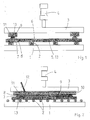
- FIG. 1 in a plan view (in the transport direction of the workpiece) illustrated device consists of a table 1 with a number of rollers 2 arranged thereon and a movable upper part 3, which can be raised and lowered by means of a fluid cylinder 4.
- a photovoltaic module 5 can be moved on the rollers 2 to drive it into the device and out of this again.
- it is not yet a photovoltaic module 5, since this consists in the current stage of the manufacturing process only of a composite of solar cells 6, which are arranged on a glass plate 13 and on their contacting elements, so usually the metallizations, each with a pastösten conductive adhesive 7 and a contact strip 8 placed thereon are provided.
- the fixation should take place so far that in later process steps in the production of the photovoltaic module, ie in particular during lamination of the same, no mechanical detachment of a contact strip 8 and / or the conductive adhesive 7 takes place and also no disturbing process gases can escape from the conductive adhesive 7 which could lead to bubbles in the later applied, important for the lamination process plastic or adhesive layer.
- FIG. 1 shown device equipped with two downholders 9, which, as FIG. 2 shows, cover the contact strips 8 substantially over the entire surface and press on the Leitkleber Mrs 7.
- the hold-down device 9 consist of a temperature-resistant above 200 ° C plastic material, and in its interior a heating element 10 is mounted in each case, which provides for a thermal basis load on the contact strip 8, for example with a temperature of 100 to 150 ° C in the contact area between the blank holder 9 and the contact strip 8.
- This temperature is with a in FIG. 2 shown temperature sensor 12 continuously measured, so that the heating element 10 can be controlled according to a predetermined set temperature.
- electrodes 11 are integrated into the hold-9, in each case in the two end regions of each contact strip 8.
- a conductive contact to the contact strip 8 can be made, so that a short-circuit current can be passed through the contact strip 8 to heat it to a temperature at which the conductive adhesive 7 is activated and optionally cured.
- the contact strip 8 heats up, ie the heat is deliberately introduced into the contact strip 8, it flows into the directly adjacent conductive adhesive 7, where it is needed. At most a fraction of this heat passes into the solar cells 6 and via the solar cells 6 in the glass plate 13, so that on the one hand, the thermal load of the solar cell 6 advantageously remains low and on the other a thermal stress in the glass plate 13 is omitted.
- the photovoltaic module of the present embodiment is a module with thin-film solar cells, which only have to be interconnected with two contact strips 8 over the width of the module.
- the intermediate solar cells 6 are already connected in series with one another, so that in the present case the two contact bands 8 are alternately heated with current pulses via the respective electrodes 11 on the right and left in order to activate the conductive adhesive layers 7.
- a typical current pulse sequence consists of several, 5 to 10 s lasting intervals with currents of about 50 to 100 A.
- the two hold-down 9 with the integrated heating elements 10 individually from the respective contact band 8 can be raised and lowered to this, the exposure time to limit the basis of the heating element 10 basic thermal load by intervals.
- the necessary for the activation of the conductive adhesive 7 heat is thus provided with an advantageously low energy consumption.
- Those elements of the module that do not necessarily have to be supplied with heat are protected in terms of their thermal load.
- a crosslinking conductive adhesive 7 by shock heating of the contact strips 8 by means of short-circuit surges in less than 60 s more than 80% crosslinking of the conductive adhesive 7 can be achieved, which is sufficient for the subsequent process steps in the rule.
- FIG. 3 also shown a separate, provided with an electrical insulation heating wire 14 between the hold-9 and the contact strip 8 and heated by passing heating current through power contacts 17. Since the heating wire 14 is provided with electrical insulation, only the heat of the heating wire 14 is transferred to the contact band 8. Current then does not flow through the contact band 8. This heating wire 14 is longer and wider than the contact strip 8, so that it is always heated completely and evenly, regardless of tolerances when placing the contact strip 8. This ensures that the ends of the contact strip 8 are securely bonded. Nevertheless, the heating wire 14 has a small cross-section to allow an accurate and flexible temperature control.
- a pulling device formed by means of two pneumatic cylinders 15 and pulleys 16 in this second embodiment keeps the heating wire 14 under tension and thus ensures that heat-related changes in length, in particular expansions of the heating wire 14 and the contact strip 8, are compensated. Since the lying under the heating wire 14 contact strip 8 is held due to mechanical friction effects together with the heating wire 14 to voltage, no wave or uneven bonding of the contact strip 8 can occur.
- the heating wire 14 has a constant and known electrical resistance, so that the contact strip 8 can be heated reproducibly, without cross-sectional tolerances of the contact strip 8 influence on the heating can have.
- the temperature of the heating wire 14 can be easily monitored and logged.
- the heating wire 14 may be formed as electrically insulated, for example, underside painted spring steel, which can be easily and quickly replaced with any contamination by adhesive residues, so that no cleaning is required.
- this heating wire 14 held on a (not shown) role and regularly be automatically clocked further to prevent contamination.
Abstract
Description
Die Erfindung betrifft ein Verfahren zum Verschalten von Solarzellen in einem Photovoltaikmodul nach dem Oberbegriff des Anspruchs 1 sowie eine Vorrichtung zur Durchführung dieses Verfahrens nach dem Oberbegriff des Anspruchs 9.The invention relates to a method for interconnecting solar cells in a photovoltaic module according to the preamble of
Bei einem Verfahren und einer Vorrichtung der vorliegenden Art wird ein elektrisch leitendes Kontaktband zum elektrischen Verschalten von zwei oder mehr Solarzellen mit einem thermisch aktivierbaren Leitkleber auf elektrische Kontaktierungselemente der beteiligten Solarzellen aufgebracht. Sodann wird der Leitkleber durch Zuführen von Wärme aktiviert, um das Kontaktband leitend an den elektrischen Kontaktierungselementen der Solarzellen festzulegen und diese hierdurch miteinander zu verschalten.In a method and a device of the present type, an electrically conductive contact strip for electrically interconnecting two or more solar cells with a thermally activatable conductive adhesive is applied to electrical contacting elements of the solar cells involved. Then, the conductive adhesive is activated by supplying heat to conductively set the contact strip to the electrical contacting elements of the solar cells and thereby interconnect them.
Photovoltaikmodule bestehen üblicherweise aus einer Anzahl von zu einem Verbund zusammengeschalteten Solarzellen, die in eine transparente Kunststoffschicht eingebettet sind, einer Glasplatte auf der sonnenzugewandten Seite des Solarzellenverbundes, einer witterungsfesten Rückseitenkaschierung, die auf die transparente Kunststoffschicht mit den Solarzellen auflaminiert wird, und einem Profilrahmen zum Schutz der Kanten. Die transparente Kunststoffschicht, in der der Solarzellenverbund eingebettet ist, besteht üblicherweise aus einem wärmeaktivierbaren Adhäsivstoff, beispielsweise aus Äthylenvinylacetat, und sorgt nach einem Laminierprozess unter Druck- und Wärmeeinwirkung für eine witterungsfeste und feuchtigkeitsdichte Verbindung der Einzelteile des Photovoltaikmoduls.Photovoltaic modules usually consist of a number of interconnected to a composite solar cells, which are embedded in a transparent plastic layer, a glass plate on the solar facing side of the solar cell assembly, a weatherproof back side lamination, which is laminated to the transparent plastic layer with the solar cells, and a profile frame for protection the edges. The transparent plastic layer, in which the solar cell assembly is embedded, usually consists of a heat-activated adhesive, such as ethylene vinyl acetate, and ensures after a lamination process under pressure and heat for a weatherproof and moisture-proof connection of the individual parts of the photovoltaic module.
Zur Herstellung des Solarzellenverbundes müssen die einzelnen Metallisierungen der Solarzelle, bzw. deren Kontaktierungselemente im vorgegebenen Schaltbild elektrisch leitend untereinander verbunden werden, so dass letztendlich alle Solarzellen des Verbundes in einem Stromkreis verschaltet sind, der über eine Steckerbuchse an der Rückseite oder der Außenseite des Photovoltaikmoduls mit einem Verbraucher geschlossen werden kann. Diese Verschaltung der einzelnen Solarzellen untereinander erfolgt über elektrisch leitende Kontaktbänder, meist verzinkte Kupferbänder mit entsprechend der zu erwartenden Stromstärken dimensioniertem Querschnitt.To produce the solar cell network, the individual metallizations of the solar cell or their contacting elements must be electrically conductively connected to each other in the predetermined circuit diagram, so that ultimately all the solar cells of the network are connected in a circuit which is connected via a socket on the back or the outside of the photovoltaic module a consumer can be closed. This interconnection of the individual solar cells with each other via electrically conductive contact strips, usually galvanized copper strips with according to the expected currents sized cross-section.
Das Aufbringen eines Kontaktbands auf die elektrischen Kontaktierungselemente der jeweilig beteiligten Solarzellen erfolgt über einen thermisch aktivierbaren Leitkleber, dessen Klebeeigenschaften durch Zuführen und Halten von Wärme eingestellt wird. Ein solcher meist pastös vorliegender Leitkleber wird zunächst auf die Kontaktierungselemente der Solarzellen aufgetragen und dann das Kontaktband aufgelegt. Soweit ein vernetzender Leitkleber verwendet wird, benötigt die Anregung der Polymerreaktion typischerweise eine Temperatur von etwa 100 bis 120 °C, während für das Aushärten eine Haltetemperatur von typischerweise ca. 140 bis 160 °C bei einer Einwirkdauer von ca. 10 bis 20 Minuten notwendig ist. Das Laminieren der Photovoltaikmodule setzt einen vollständig ausgehärteten Leitkleber voraus, da aus einer unvollständig vernetzten Kleberschicht prozesskritische, bleibende Gasblasen im Modul erzeugt würden.The application of a contact strip to the electrical contacting elements of the respective involved solar cells via a thermally activated conductive adhesive whose adhesive properties is adjusted by supplying and holding heat. Such a mostly pasty conductive adhesive is first applied to the contacting of the solar cells and then placed the contact strip. As far as a crosslinking conductive adhesive is used, the excitation of the polymer reaction typically requires a temperature of about 100 to 120 ° C, while for curing a holding temperature of typically about 140 to 160 ° C at an exposure time of about 10 to 20 minutes is necessary , The lamination of the photovoltaic modules requires a completely cured conductive adhesive, as from an incompletely crosslinked adhesive layer process-critical, permanent gas bubbles would be generated in the module.
Nach dem derzeitigen Stand der Technik wird das vorliegende Verfahren solcherart durchgeführt, dass zunächst ein Leitkleber auf die Kontaktierungselemente der Solarzellen aufgebracht und das Kontaktband auf den Leitkleber aufgelegt wird. Sodann wird das Kontaktband auf dem Leitkleber bzw. auf den beteiligten Solarzellen und der Glasplatte mit Klebestreifen fixiert. Der so vorbereitete, auf der Glasplatte aufliegende oder - im Falle von Dünnschichtsolarzellen - auf der Substratplatte befindliche Solarzellenverbund wird nachfolgend in einen eigens für die Leitkleberhärtung vorgesehenen Ofen verbracht, wo der Leitkleber aktiviert und gehärtet wird. Davon abgesehen, dass fertig metallisierte und kontaktierte Solarzellen möglichst wenig thermisch behandelt werden sollten, um keine Verunreinigungen in das Halbleitermaterial einzubringen, ist das Aufheizen des (halbfertigen) Moduls auf die Aushärtetemperatur des Leitklebers (also auf um die 150 °C) auch unter energetischen Gesichtspunkten und somit vom Kostenaufwand bei der Produktion her nicht optimal. Schließlich benötigt der Aushärteofen wegen der relativ langen Aushärtedauer einen nicht unerheblichen Raum am Produktionsstandort. Um reproduzierbare, konstante Prozessbedingungen bei der Weiterverarbeitung der Photovoltaikmodule zu gewährleisten, müssen diese zudem vor dem Weiterprozessieren wieder kontrolliert abgekühlt werden. Schließlich ergibt sich durch das Aufheizen und Abkühlen der Glasplatte des Photovoltaikmoduls ein thermischer Stress im Glas, der unter Umständen beim weiteren Prozessieren zu Glasbruch führen kann.According to the current state of the art, the present method is carried out such that first a conductive adhesive is applied to the contacting elements of the solar cells and the contact strip is placed on the conductive adhesive. Then the contact tape is fixed on the conductive adhesive or on the solar cells involved and the glass plate with adhesive tape. The thus prepared, resting on the glass plate or - in the case of thin-film solar cells - located on the substrate plate solar cell assembly is subsequently spent in a specially provided for the Leitkleberhärtung furnace where the conductive adhesive is activated and cured. Apart from that, finished metallized and contacted solar cells are thermally treated as little as possible should be, in order to introduce no impurities in the semiconductor material, the heating of the (semi-finished) module to the curing temperature of the conductive adhesive (ie to around 150 ° C) is not optimal also from an energetic point of view and thus from the cost of production. Finally, the curing oven requires a considerable space at the production site because of the relatively long curing time. In order to ensure reproducible, constant process conditions during the further processing of the photovoltaic modules, they must also be cooled in a controlled manner before further processing. Finally, the heating and cooling of the glass plate of the photovoltaic module results in a thermal stress in the glass, which under certain circumstances can lead to glass breakage during further processing.
Der vorliegenden Erfindung liegt daher die Aufgabe zugrunde, ein Verfahren und eine Vorrichtung der eingangs genannten Art hinsichtlich der genannten Probleme zu verbessern, also die thermische Belastung der verschiedenen Elemente des Photovoltaikmoduls in Grenzen zu halten und die Gefahr eines Glasbruchs zu verringern.The present invention is therefore based on the object to improve a method and an apparatus of the type mentioned in terms of the problems mentioned, ie to keep the thermal load of the various elements of the photovoltaic module within limits and to reduce the risk of glass breakage.
Gelöst ist diese Aufgabe durch ein Verfahren mit den Merkmalen des Anspruchs 1 sowie durch eine Vorrichtung mit den Merkmalen des Anspruchs 9. Vorteilhafte Weiterbildungen des erfindungsgemäßen Verfahrens finden sich in den Ansprüchen 2 bis 8; bevorzugte Ausgestaltungen der erfindungsgemäßen Vorrichtung sind in den Ansprüchen 10 bis 17 niedergelegt.This object is achieved by a method having the features of
Die vorliegende Erfindung unterscheidet sich vom bisherigen Stand der Technik also vornehmlich dadurch, dass das Aktivieren des Leitklebers zwischen dem Kontaktband und den Kontaktierungselementen der beteiligten Solarzellen durch ein gezieltes Erwärmen des Kontaktbandes erfolgt. Dadurch, dass die Wärme in das Kontaktband eingebracht wird, und von dort in den Leitkleber fließt, also an diejenige Stelle, an der die Wärme benötigt wird, bleiben die restlichen Teile des Photovoltaikmoduls, in diesem Stadium des Herstellungsprozesses also insbesondere die Solarzellen und die Glasplatte, thermisch unbelastet. Das Kontaktband selbst ist thermisch unempfindlich, so dass die beschriebenen bisherigen Problemstellungen des Verfahrens gelöst sind.The present invention thus differs from the prior art primarily in that the activation of the conductive adhesive between the contact band and the contacting elements of the solar cells involved takes place by targeted heating of the contact band. Characterized in that the heat is introduced into the contact strip, and flows from there into the conductive adhesive, ie at the point where the heat is needed, remain the remaining parts of the photovoltaic module, in this stage of the manufacturing process so in particular the solar cells and the glass plate , thermally unloaded. The contact band itself is thermally insensitive, so that the described previous problems of the method are solved.
Um die Wärme gezielt in das Kontaktband einzubringen, kann vorgesehen sein, auf das Kontaktband ein elektrisches Widerstands-Heizelement, insbesondere einen Heizdraht, aufzulegen, und zwar solcherart, dass eine wärmeleitende Verbindung zwischen dem Heizelement und dem Kontaktband hergestellt wird, diese beiden Bauteile jedoch gegeneinander elektrisch isoliert sind. Auf diese Weise kann das Widerstands-Heizelement durch Einleiten von Strom sehr leicht und kontrolliert erhitzt werden und die Wärme gezielt an das Kontaktband abgeben. Da das Widerstands-Heizelement sehr genau gefertigt sein kann, ergeben sich hinsichtlich des elektrischen Widerstands und des über die gesamte Länge konstanten Querschnitts des Widerstandselements reproduzierbare Ergebnisse für die mit einer bestimmten Strommenge erzeugte Temperatur. Bei Bedarf ist es auch möglich, im Widerstands-Heizelement einen Temperatursensor zu integrieren, um den Prozess kontrolliert überwachen und führen zu können.In order to introduce the heat targeted in the contact band, it may be provided on the contact strip an electrical resistance heating element, in particular a heating wire, hang up, in such a way that a heat-conducting connection between the heating element and the contact strip is made, but these two components against each other are electrically isolated. In this way, the resistance heating element can be heated by introducing current very easily and controlled and deliver the heat targeted to the contact band. Since the resistance heating element can be made very accurately, results in terms of electrical resistance and over the entire length constant cross section of the resistive element reproducible results for the temperature generated with a certain amount of current. If necessary, it is also possible to integrate a temperature sensor in the resistance heating element in order to monitor and guide the process in a controlled manner.
Vorzugsweise wird das elektrische Widerstands-Heizelement mit einer Zugeinrichtung auf Spannung gehalten, um wärmebedingte Längenausdehnungen zu kompensieren. Diese Zugspannung wirkt sich auch auf das direkt unter dem Heizelement liegende Kontaktband, so dass auch bei diesem keine wärmebedingte Wellenbildung oder ungleichmäßige Verklebung entstehen kann.Preferably, the electrical resistance heating element is held with tension by a pulling device to compensate for heat-related length expansions. This tensile stress also affects the contact band lying directly under the heating element, so that no heat-related wave formation or uneven bonding can occur in this case as well.
Als Widerstands-Heizelement kann ein Heizdraht aus elektrisch isoliertem Federstahl verwendet werden, der sehr einfach und schnell getauscht werden kann, wenn er beispielsweise durch Kleberreste verschmutzt worden ist. Denkbar wäre auch, einen solchen Heizdraht auf einer Rolle vorzuhalten und regelmäßig automatisch weiterzutakten, um solchen Verschmutzungen vorzubeugen.As a resistance heating element, a heating wire made of electrically insulated spring steel can be used, which can be exchanged very easily and quickly, for example, if it has been contaminated by adhesive residues. It would also be conceivable to keep such a heating wire on a roll and automatically continue to act regularly to prevent such contamination.
Besonders bevorzugt ist es im Rahmen der vorliegenden Erfindung, wenn das Kontaktband mittels Durchleiten eines Kurzschlussstroms erwärmt wird. Hierdurch nutzt man also den Ohmschen Widerstand des Kontaktbands aus, um dieses zu erhitzen. Ein auf den Leitungsquerschnitt des entsprechenden Kontaktbandes abgestimmter Kurzschlussstrom kann durch Widerstanderwärmung innerhalb weniger Sekunden Temperaturen von 150 bis 180 °C erzeugen.In the context of the present invention, it is particularly preferred when the contact strip is heated by passing a short-circuit current. Thus, one uses the ohmic resistance of the contact band to heat it. A short circuit current adapted to the line cross section of the corresponding contact strip can generate temperatures of 150 to 180 ° C within a few seconds by resistance heating.
Neben dem großen Vorteil, dass hierdurch sehr einfach, nämlich durch elektrische Kontaktierung der Kontaktbänder, die erfindungsgemäß gezielte Erwärmung derselben auf die benötigte Temperatur erreicht werden kann, ergibt sich der weitere Vorteil, dass die benötigte Temperatur extrem schnell erreicht werden kann, beispielsweise in einem Zeitintervall von etwa 10 Sekunden, was einem Temperaturgradienten von ca. 1000 °C/min entspricht. Besonders vorteilhaft ist dies deswegen, da viele thermisch aktivierbare Klebersysteme, soweit sie vernetzend sind, unter großen Temperaturgradienten schneller polymerisieren als unter kleinen Temperaturgradienten.In addition to the great advantage that this very simple, namely by electrical contacting of the contact strips, the invention targeted heating of the same can be achieved to the required temperature, there is the further advantage that the required temperature can be reached extremely quickly, for example in a time interval of about 10 seconds, which corresponds to a temperature gradient of about 1000 ° C / min. This is particularly advantageous because many thermally activatable adhesive systems, as far as they are crosslinking polymerize faster under large temperature gradients than under small temperature gradients.
Um die thermische Belastung der Solarzellen und der Glasplatte so klein wie möglich zu halten, sowie für eine einfachere Regelung des per Kurzschlussstrom in das Kontaktband eingebrachten Wärme ist es bevorzugt, dass der Kurzschlussstrom in mehreren aufeinanderfolgenden Stromstößen durch das Kontaktband geleitet wird, und zwar insbesondere mit einer Zeitdauer von ca. 1 Sekunde bis ca. 10 Sekunden. Auch wenn ein Widerstands-Heizelement verwendet wird, um das Kontaktband indirekt durch einen Heizstrom zu erwärmen, können Stromstöße der oben genannten Art vorgesehen sein.In order to keep the thermal load of the solar cells and the glass plate as small as possible, as well as for easier control of the introduced by short-circuit current in the contact band heat, it is preferred that the short-circuit current is passed in several successive power surges through the contact band, in particular with a period of about 1 second to about 10 seconds. Even if a resistance heating element is used to heat the contact strip indirectly by a heating current, surges of the above type may be provided.
Insbesondere bei Dünnschichtsolarzellen, die bereits seriell untereinander verschaltet sind, ist es zur Vermeidung von Schäden vorteilhaft, wenn die beiden Kontaktbänder der einzelnen Dünnschichtmodule mit abwechselnden Stromstößen beaufschlagt oder nacheinander aufgeheizt werden, also niemals beide Kontaktbänder gleichzeitig bestromt oder aufgeheizt werden.In particular, in thin-film solar cells, which are already connected in series with each other, it is advantageous to avoid damage when the two contact strips of the individual thin-film modules acted upon by alternating surges or heated sequentially, so never both contact bands are energized or heated simultaneously.
Unabhängig davon, ob die Erwärmung des Kontaktbandes mittels Durchleiten eines Stroms oder auf andere Weise erfolgt, kann diese Erwärmung auf eine Temperatur vorgenommen werden, die höher liegt als die bisher für die Aktivierung bzw. Aushärtung der Leitkleber verwendete Temperatur, ohne dass die Solarzellen oder die Glasplatte Schaden nehmen; denn diese werden hierbei nicht oder nur kaum erwärmt. Durch diese möglichen höheren Temperaturen verkürzt sich die Aushärtezeit der üblichen Leitkleber nochmals, was die Prozessdauer naturgemäß verringert. Soweit die Erwärmung des Kontaktbandes mittels Durchleiten eines Kurzschlussstroms oder mittels eines aufgelegten Widerstands-Heizelements erfolgt, ist es bevorzugt, Kurzschlussströme oder Heizströme mit einer Stromstärke von ca. 10A bis 100A zu verwenden.Regardless of whether the heating of the contact strip by means of passing a current or otherwise takes place, this heating can be carried out to a temperature which is higher than the temperature previously used for the activation or curing of the conductive adhesive, without the solar cells or the Damage glass plate; because these are not or only slightly heated here. These possible higher temperatures shorten the curing time of the usual conductive adhesive again, which naturally reduces the duration of the process. As far as the heating of the contact strip by passing a short-circuit current or by means of an on-hook Resistance heating element, it is preferred to use short-circuit currents or heating currents with a current of about 10A to 100A.
Da sich das Kontaktband bei Erwärmung ausdehnt, ist es im Rahmen der vorliegenden Erfindung bevorzugt, einen Niederhalter zu verwenden, der das Kontaktband zumindest während des Erwärmens auf den Leitkleber drückt und hierdurch ein Aufwölben des Kontaktbandes verhindert. Dieser Niederhalter überdeckt das Kontaktband vorzugsweise im Wesentlichen ganzflächig und besteht aus elektrisch nichtleitendem, temperaturbeständigem Material, also beispielsweise einem Kunststoff (z.B. PTFE oder PEEK). Die elektrisch nicht leitende Ausbildung des Niederhalters ermöglicht eine Kombination desselben mit der bevorzugten erfindungsgemäßen Verfahrensvariante, bei der das Kontaktband mittels Durchleitens eines Kurzschlussstroms erwärmt wird. Denn die Elektroden zum Durchleiten des Kurzschlussstroms durch das Kontaktband können dann insbesondere in den Niederhalter integriert sein, so dass sich eine separate Kontaktierung des Kontaktbandes erübrigt.Since the contact band expands when heated, it is preferable in the present invention to use a hold-down device which presses the contact band at least during heating to the conductive adhesive and thereby prevents bulging of the contact band. This hold-down device preferably covers the contact band essentially over the whole area and consists of electrically nonconductive, heat-resistant material, for example a plastic (for example PTFE or PEEK). The electrically non-conductive design of the blank holder allows a combination of the same with the preferred variant of the method according to the invention, in which the contact strip is heated by passing a short-circuit current. Because the electrodes for passing the short-circuit current through the contact strip can then be integrated in particular in the hold-down, so that a separate contacting of the contact strip is unnecessary.
Die Temperatur des Kontaktbandes wird vorzugsweise durch einen Temperaturfühler überwacht, wobei der Temperaturfühler auch als Messgröße für eine Regelung der Temperatur des Kontaktbandes verwendet werden kann. Zweckmäßigerweise ist dieser Temperaturfühler am Niederhalter angebracht, soweit ein solcher vorhanden ist.The temperature of the contact band is preferably monitored by a temperature sensor, wherein the temperature sensor can also be used as a parameter for controlling the temperature of the contact band. Conveniently, this temperature sensor is attached to the hold-down, as far as such is present.
Das erfindungsgemäße gezielte Erwärmen des Kontaktbandes kann alternativ zum Durchleiten eines Kurzschlussstroms dadurch erfolgen, dass das Kontaktband durch ein daran anliegendes Heizelement mittels Wärmeleitung erwärmt wird. Ein solches Heizelement ist vorzugsweise an das Kontaktband anstellbar und von diesem abstellbar. Hierdurch kann beispielsweise das Heizelement bedarfsweise in Intervallen vom Kontaktband entfernt und wieder an dieses angelegt werden. Bevorzugterweise kann der Niederhalter, soweit ein solcher vorhanden ist, als Heizelement verwendet werden bzw. kann das Heizelement in den Niederhalter integriert werden.The targeted heating of the contact strip according to the invention can alternatively be carried out by passing a short-circuit current in that the contact strip is heated by means of heat conduction by a heating element abutting against it. Such a heating element is preferably engageable with the contact band and can be turned off from it. As a result, for example, the heating element, if necessary, removed at intervals from the contact strip and applied again to this. Preferably, the hold-down, if any, can be used as a heating element or the heating element can be integrated into the hold-down device.
Die Einbringung von Wärme in das Kontaktband durch ein daran anliegendes Heizelement bzw. ein in einen Niederhalter integriertes Heizelement kann auch zusätzlich zum Erwärmen des Kontaktbands mittels Durchleitens eines Kurzschlussstroms erfolgen. Das Heizelement sorgt dann für eine Wärmegrundlast auf das Kontaktband, die zum Beispiel den Leitkleber aktiviert. Diese Wärmegrundlast kann besonders gut über einen Temperaturfühler geregelt werden. Die Erwärmung des Kontaktbandes auf Aushärtetemperatur des Leitklebers - und hier vorzugsweise auf eine besonders hohe Aushärtetemperatur, um die Aushärtezeit klein zu halten - wird dann durch zusätzliches Durchleiten eines Kurzschlussstroms im Kontaktband erzeugt, gegebenenfalls mit intervallartigen Stromstößen.The introduction of heat into the contact band by an adjacent heating element or in a hold-down integrated heating element can also in addition to heating the contact strip by passing a short-circuit current done. The heating element then provides a thermal basis load on the contact strip, which activates the conductive adhesive, for example. This basic heat load can be controlled particularly well via a temperature sensor. The heating of the contact strip to the curing temperature of the conductive adhesive - and here preferably to a particularly high curing temperature to keep the curing time small - is then generated by additionally passing a short-circuit current in the contact band, optionally with intermittent power surges.
Versuche der Anmelderin haben in diesem Zusammenhang gezeigt, dass die Aushärtung des Leitklebers nur zu etwa 70 bis 80 % erfolgen muss, um die nachfolgenden Prozessschritte ohne Beeinträchtigungen durchlaufen zu können. Das Kontaktband und/oder der Leitkleber lösen sich dann nicht mehr ab, und es können aus dem Leitkleber keine störenden Prozessgase mehr austreten, die im Endeffekt zu Blasen im Photovoltaikmodul führen könnten. Die Aushärtedauer und damit die Prozessdauer zum Verschalten der Solarzellen wird durch diese erfinderische Erkenntnis nochmals reduziert, wobei die Wärmebelastung der Solarzellen bzw. der Glasplatte nochmals geringer bleibt.Experiments by the Applicant have shown in this context that the curing of the conductive adhesive must be done only about 70 to 80% in order to be able to go through the subsequent process steps without impairment. The contact strip and / or the conductive adhesive then no longer detach, and it can no longer escape from the conductive adhesive annoying process gases, which could eventually lead to bubbles in the photovoltaic module. The curing time and thus the process time for interconnecting the solar cells is further reduced by this inventive knowledge, the heat load of the solar cell or the glass plate remains lower.
Insbesondere aufgrund der optional vorhandenen Niederhalter, jedoch auch schon alleine deswegen, weil die Erwärmung des Kontaktbandes sehr schnell und gegebenenfalls pulsartig erfolgt, ist ein Aufwölben des Kontaktbandes nicht mehr zu befürchten, so dass auf die bislang generell notwendigen Klebstreifen zur Fixierung des Kontaktbandes auf dem Leitkleber verzichtet werden kann.In particular, due to the optional existing hold-down, but also alone because the heating of the contact strip is very fast and possibly pulse-like, a bulging of the contact band is no longer to be feared, so that the hitherto generally necessary adhesive tape for fixing the contact strip on the conductive adhesive can be waived.
Zwei Ausführungsbeispiele für eine erfindungsgemäß ausgestaltete Vorrichtung werden im folgenden anhand der beigefügten Zeichnungen näher beschrieben und erläutert. Es zeigen:
Figur 1- einen schematischen Schnitt durch ein erstes Ausführungsbeispiel einer erfindungsgemäßen Vorrichtung, quer zur Transportrichtung;
Figur 2- eine schematische Seitenansicht zur Schnittdarstellung nach
Figur 1 Figur 3- eine schematische Seitenansicht eines zweiten Ausführungsbeispiels.
- FIG. 1
- a schematic section through a first embodiment of a device according to the invention, transverse to the transport direction;
- FIG. 2
- a schematic side view of the sectional view according to
FIG. 1 ; - FIG. 3
- a schematic side view of a second embodiment.
Die in
Zu diesem Zweck ist die in
Wie in
Beim Photovoltaikmodul des vorliegenden Ausführungsbeispiels handelt es sich um ein Modul mit Dünnschichtsolarzellen, die über die Breite des Moduls lediglich mit zwei Kontaktbändern 8 verschaltet werden müssen. Die zwischenliegenden Solarzellen 6 sind bereits seriell miteinander verschaltet, so dass vorliegend die beiden Kontaktbänder 8 über die jeweiligen Elektroden 11 rechts und links abwechselnd mit Stromstößen erhitzt werden, um die Leitkleberschichten 7 zu aktivieren. Eine typische Stromstoßfolge besteht aus mehreren, 5 bis 10 s andauernden Intervallen mit Stromstärken von ca. 50 bis 100 A. Darüber hinaus sind die beiden Niederhalter 9 mit den integrierten Heizelementen 10 einzeln vom jeweiligen Kontaktband 8 weg anhebbar und auf dieses absenkbar, um die Einwirkdauer der vom Heizelement 10 herrührenden Wärmegrundlast durch Intervalle zu begrenzen.The photovoltaic module of the present embodiment is a module with thin-film solar cells, which only have to be interconnected with two
Die für die Aktivierung der Leitkleber 7 notwendige Wärme wird demnach mit einem vorteilhaft geringen Energieaufwand bereitgestellt. Diejenigen Elemente des Moduls, die nicht unbedingt mit Wärme beaufschlagt werden müssen, werden hinsichtlich ihrer thermischen Belastung geschont. Darüber hinaus erfolgt das Aktivieren des thermisch reaktiven Leitklebers 7 durch die höheren möglichen Temperaturen an diesem Ort sowie die hohen Temperaturgradienten beim Aufheizen besonders schnell, so dass das erfindungsgemäße Verfahren den Prozessschritt des Aufbringens von Kontaktbändern 8 schließlich deutlich verkürzt. Beispielsweise kann bei Verwendung eines vernetzenden Leitklebers 7 durch Stoßerwärmung der Kontaktbänder 8 mittels Kurschluss-Stromstößen in weniger als 60 s mehr als 80 % Vernetzung des Leitklebers 7 erreicht werden, was für die nachfolgenden Prozessschritte in der Regel ausreicht.The necessary for the activation of the conductive adhesive 7 heat is thus provided with an advantageously low energy consumption. Those elements of the module that do not necessarily have to be supplied with heat are protected in terms of their thermal load. In addition, takes place the activation of the thermally reactive conductive adhesive 7 by the higher possible temperatures at this location and the high temperature gradients during heating particularly fast, so that the inventive method finally significantly reduces the process step of applying
Wenn das Durchleiten von hohen Strömen durch das Kontaktband 8 vermieden werden soll, kann in einem anderen, in
Eine mittels zweier Pneumatikzylinder 15 und Umlenkrollen 16 gebildete Zugeinrichtung in diesem zweiten Ausführungsbeispiel hält den Heizdraht 14 unter Spannung und sorgt somit dafür, dass wärmebedingte Längenänderungen, insbesondere Ausdehnungen des Heizdrahts 14 und des Kontaktbandes 8, kompensiert werden. Da das unter dem Heizdraht 14 liegende Kontaktband 8 wegen mechanischer Reibungseffekte zusammen mit dem Heizdraht 14 auf Spannung gehalten wird, kann keine Wellenbildung oder ungleichmäßige Verklebung des Kontaktbandes 8 auftreten.A pulling device formed by means of two
Der Heizdraht 14 besitzt einen konstanten und bekannten elektrischen Widerstand, so dass das Kontaktband 8 reproduzierbar erwärmt werden kann, ohne dass Querschnittstoleranzen des Kontaktbandes 8 Einfluss auf die Erwärmung haben können. Die Temperatur des Heizdrahtes 14 kann einfach überwacht und protokolliert werden.The
Nach diesem Ausführungsbeispiel ist es nicht notwendig, mehrere Kontaktbänder 8 eines Photovoltaik-Moduls 5 abwechselnd zu erwärmen; dies kann vielmehr gleichzeitig geschehen, so dass sich die Taktzeit zur Verschaltung des Photovoltaik-Moduls 5 verkürzt.According to this embodiment, it is not necessary to alternately heat a plurality of
Der Heizdraht 14 kann als elektrisch isolierter, beispielsweise unterseitig lackierter Federstahl ausgebildet sein, der bei einer etwaigen Verschmutzung durch Kleberreste einfach und schnell getauscht werden kann, so dass keine Reinigung erforderlich ist. Gegebenenfalls kann dieser Heizdraht 14 auf einer (nicht dargestellten) Rolle vorgehalten und regelmäßig automatisch weitergetaktet werden, um Verschmutzungen vorzubeugen.The
Claims (17)
dadurch gekennzeichnet,
dass das Aktivieren des Leitklebers (7) durch ein gezieltes Erwärmen des Kontaktbandes (8) erfolgt.Method for interconnecting solar cells in a photovoltaic module, wherein an electrically conductive contact strip (8) for electrically interconnecting two or more solar cells (6) with a thermally activated conductive adhesive (7) applied to electrical contacting elements of the solar cells involved (6) and the conductive adhesive ( 7) is activated by supplying heat in order to determine the contact band (8) in a conductive manner on the electrical contacting elements,
characterized,
in that the activating of the conductive adhesive (7) takes place by a specific heating of the contact strip (8).
dadurch gekennzeichnet,
dass das Kontaktband (8) mittels Durchleiten eines Kurzschlussstroms erwärmt wird und/oder dass das gezielte Erwärmen des Kontaktbandes (8) durch wärmeleitendes und elektrisch isoliertes Auflegen eines elektrischen Widerstands-Heizelements (14) auf das Kontaktband (8) und Durchleiten eines Heizstroms durch das Widerstands-Heizelement (14) erfolgt.Method according to claim 1,
characterized,
that the contact strip (8) is heated by passing a short-circuit current and / or that the targeted heating of the contact strip (8) by thermally conductive and electrically insulated placing an electrical resistance heating element (14) on the contact strip (8) and passing a heating current through the Resistance heating element (14) takes place.
dadurch gekennzeichnet,
dass der Kurzschlussstrom oder der Heizstrom in mehreren aufeinanderfolgenden Stromstößen durch das Kontaktband (8) oder das Widerstands-Heizelement (14) geleitet wird.Method according to claim 2
characterized,
in that the short-circuit current or the heating current is conducted through the contact band (8) or the resistance heating element (14) in a plurality of successive power surges.
dadurch gekennzeichnet,
dass mindestens zwei Kontaktbänder (8) mit abwechselnden Stromstößen beaufschlagt werden.Method according to one of claims 2 or 3,
characterized,
that at least two contact strips (8) are subjected to alternating power surges.
dadurch gekennzeichnet,
dass das Kontaktband (8) während des Erwärmens mittels mindestens eines Niederhalters (9) auf den Leitkleber (7) gedrückt wird.Method according to at least one of claims 1 to 4,
characterized,
that the contact strip (8) during the heating by at least one holding-down device (9) onto the conductive adhesive (7) is pressed.
dadurch gekennzeichnet,
dass das Kontaktband (8) durch ein Heizelement (10) mittels Wärmeleitung erwärmt wird.Method according to at least one of claims 1 to 5,
characterized,
that the contact strip (8) is heated by a heating element (10) by means of heat conduction.
dadurch gekennzeichnet,
dass der Niederhalter (9) als Heizelement (10) verwendet wird.Process according to claims 5 and 6,
characterized,
that the holding-down device (9) is used as a heating element (10).
dadurch gekennzeichnet,
dass die Temperatur des Kontaktbandes (8) mittels eines Temperaturfühlers (12) überwacht und/oder geregelt wird.Method according to at least one of claims 1 to 7,
characterized,
is that the temperature of the contact strip (8) by means of a temperature sensor (12) monitors and / or regulated.
gekennzeichnet durch Mittel (10, 11) zum gezielten Erwärmen des Kontaktbandes (8).Device for interconnecting solar cells in a photovoltaic module by means of an electrically conductive contact strip (8) which is placed with a thermally activatable conductive adhesive (7) on electrical contacting elements of the solar cells involved (6), with a method according to at least one of claims 1 to 8,
characterized by means (10, 11) for the targeted heating of the contact strip (8).
dadurch gekennzeichnet,
dass die Erwärmungsmittel Elektroden (11) zum Durchleiten eines Kurzschlussstroms durch das Kontaktband (8) umfassen.Device according to claim 9,
characterized,
in that the heating means comprise electrodes (11) for passing a short-circuit current through the contact band (8).
dadurch gekennzeichnet,
dass mindestens ein Niederhalter (9) vorgesehen ist, um das Kontaktband (8) während des Erwärmens auf den Leitkleber (7) zu drücken.Device according to one of claims 9 or 10,
characterized,
in that at least one hold-down device (9) is provided in order to press the contact strip (8) onto the conductive adhesive (7) during the heating.
dadurch gekennzeichnet,
dass die Elektroden (11) in den Niederhalter (9) integriert sind.Device according to claims 10 and 11,
characterized,
that the electrodes (11) are integrated in the holding-down device (9).
dadurch gekennzeichnet,
dass ein bedarfsweise auf das Kontaktband (8) auflegbares Heizelement (10) vorgesehen ist.Device according to at least one of claims 9 to 12,
characterized,
that, if necessary, on the contact strip (8) auflegbares heating element (10) is provided.
dadurch gekennzeichnet,
dass der Niederhalter (9) mit dem Heizelement (10) versehen ist.Device according to one of claims 11 or 12 and claim 13,
characterized,
that the holding-down device (9) with the heating element (10) is provided.
dadurch gekennzeichnet,
dass der Niederhalter (9) das Kontaktband (8) im Wesentlichen ganzflächig überdeckt.Device according to at least one of claims 11 to 14,
characterized,
that the holding-down device (9) the contact strip (8) substantially over the whole area covered.
dadurch gekennzeichnet,
dass ein Temperaturfühler (12) zur Überwachung und/oder Regelung der Erwärmung des Kontaktbandes (8) vorhanden ist.Device according to at least one of claims 9 to 15,
characterized,
that a temperature sensor (12) for monitoring and / or controlling the heating of the contact strip (8) is present.
dadurch gekennzeichnet,
dass der Niederhalter (9) aus elektrisch nichtleitendem, temperaturbeständigem Material, insbesondere aus Kunststoff, besteht.Device according to claim 11,
characterized,
that the hold-down device (9) consists of electrically non-conductive, temperature-resistant material, in particular of plastic.
Applications Claiming Priority (2)
| Application Number | Priority Date | Filing Date | Title |
|---|---|---|---|
| DE200810034080 DE102008034080A1 (en) | 2008-07-21 | 2008-07-21 | Solar cells switching method for photovoltaic module, involves activating thermally activatable conductive adhesive by applying heat, to form contact strip conductive to conductive elements |
| DE102009013524 | 2009-03-19 |
Publications (1)
| Publication Number | Publication Date |
|---|---|
| EP2148376A2 true EP2148376A2 (en) | 2010-01-27 |
Family
ID=41323591
Family Applications (1)
| Application Number | Title | Priority Date | Filing Date |
|---|---|---|---|
| EP20090009354 Withdrawn EP2148376A2 (en) | 2008-07-21 | 2009-07-17 | Method and device for switching solar cells in a photovoltaic module |
Country Status (1)
| Country | Link |
|---|---|
| EP (1) | EP2148376A2 (en) |
Cited By (4)
| Publication number | Priority date | Publication date | Assignee | Title |
|---|---|---|---|---|
| DE102011001673A1 (en) | 2011-03-30 | 2012-10-04 | Solarwatt Ag | Solar cell used in solar panel, has front soldered surface whose alignment line is not congruently arranged with respect to alignment line of front soldered surface |
| CN104143585A (en) * | 2013-04-24 | 2014-11-12 | 维斯慕达有限公司 | Method for processing photovoltaic panel with back-contact architecture |
| CN105352877A (en) * | 2015-11-09 | 2016-02-24 | 江西瑞晶太阳能科技有限公司 | Hot and humid detection method for photovoltaic solder strip |
| CN110148581A (en) * | 2018-02-10 | 2019-08-20 | 姜富帅 | A kind of metal-semiconductor metallization process and method |
-
2009
- 2009-07-17 EP EP20090009354 patent/EP2148376A2/en not_active Withdrawn
Cited By (7)
| Publication number | Priority date | Publication date | Assignee | Title |
|---|---|---|---|---|
| DE102011001673A1 (en) | 2011-03-30 | 2012-10-04 | Solarwatt Ag | Solar cell used in solar panel, has front soldered surface whose alignment line is not congruently arranged with respect to alignment line of front soldered surface |
| DE202011110751U1 (en) | 2011-03-30 | 2016-01-27 | Solarwatt Gmbh | Solar cell with metallic contact bands |
| CN104143585A (en) * | 2013-04-24 | 2014-11-12 | 维斯慕达有限公司 | Method for processing photovoltaic panel with back-contact architecture |
| CN104143585B (en) * | 2013-04-24 | 2017-08-18 | 维斯慕达有限公司 | Method for handling the photovoltaic panel with back touching type architecture |
| CN105352877A (en) * | 2015-11-09 | 2016-02-24 | 江西瑞晶太阳能科技有限公司 | Hot and humid detection method for photovoltaic solder strip |
| CN110148581A (en) * | 2018-02-10 | 2019-08-20 | 姜富帅 | A kind of metal-semiconductor metallization process and method |
| CN110148581B (en) * | 2018-02-10 | 2022-05-17 | 姜富帅 | Metallization process and method of metal-semiconductor |
Similar Documents
| Publication | Publication Date | Title |
|---|---|---|
| EP1997614B1 (en) | Method and device for laminating mainly plate-shaped workpieces with the use of pressure and heat | |
| DE102016009560B4 (en) | Process to improve the ohmic contact behavior between a contact grid and an emitter layer of a silicon solar cell | |
| DE19834459B4 (en) | Solar battery module and method for its manufacture | |
| EP2141018A2 (en) | Method and device for laminating mainly plate-shaped workpieces with the use of pressure and heat | |
| DE2365831A1 (en) | LAYERED SAFETY GLASS | |
| EP2148376A2 (en) | Method and device for switching solar cells in a photovoltaic module | |
| WO2008014900A1 (en) | Method for fitting a connecting conductor to a photovoltaic solar cell | |
| DE102008046330A1 (en) | Method for soldering contact wires to solar cells | |
| EP2390904A2 (en) | Method for low temperature pressure interconnection of two connection partners and assembly manufactured using same | |
| EP2133923A2 (en) | Recycling method for thin layer solar cell modules | |
| DE102013108563A1 (en) | Method and device for resistance welding of sandwich panels | |
| EP2859987A1 (en) | Component assembly | |
| EP3108019B1 (en) | Method for conductively heating sheet metal in pairs, and heating device for carrying out said method | |
| DE102009031227A1 (en) | Device for soldering a conductor to a circuit carrier | |
| WO2013034137A2 (en) | Moulding press/laminator | |
| DE102008034080A1 (en) | Solar cells switching method for photovoltaic module, involves activating thermally activatable conductive adhesive by applying heat, to form contact strip conductive to conductive elements | |
| EP1525900A1 (en) | Process for the formation of electrical contactable conductors on conductive polymer electrode and products obtainable therewith | |
| DE2855051A1 (en) | METHOD AND DEVICE FOR CONNECTING PLASTIC PARTS | |
| DE102010054400A1 (en) | Series connection method of solar cells of solar cell array, pre-fixing cell connectors on negative or positive terminal contact guide elements of adjacent cells by setting solder points between connectors and guide elements | |
| DE102018106509B4 (en) | Method and device for manufacturing a conveyor belt with embedded flat coils | |
| EP2234749B1 (en) | Method for producing a soldered connection between two components | |
| DE102009042148A1 (en) | Multi-platen press for laminating e.g. solar modules from composite material under pressure and thermal effect, has hydraulic and vacuum units producing pressure in platen, where vacuum unit is interacted with flexible pressing device | |
| DE102009003495C5 (en) | Soldering and soldering device | |
| DE202020103337U1 (en) | Contact device | |
| DE102014101489B4 (en) | Process for the production of an optoelectronic arrangement |
Legal Events
| Date | Code | Title | Description |
|---|---|---|---|
| PUAI | Public reference made under article 153(3) epc to a published international application that has entered the european phase |
Free format text: ORIGINAL CODE: 0009012 |
|
| AK | Designated contracting states |
Kind code of ref document: A2 Designated state(s): AT BE BG CH CY CZ DE DK EE ES FI FR GB GR HR HU IE IS IT LI LT LU LV MC MK MT NL NO PL PT RO SE SI SK SM TR |
|
| AX | Request for extension of the european patent |
Extension state: AL BA RS |
|
| STAA | Information on the status of an ep patent application or granted ep patent |
Free format text: STATUS: THE APPLICATION IS DEEMED TO BE WITHDRAWN |
|
| 18D | Application deemed to be withdrawn |
Effective date: 20130201 |