EP2148299A1 - Apparatus and method for producing improved quality signals - Google Patents
Apparatus and method for producing improved quality signals Download PDFInfo
- Publication number
- EP2148299A1 EP2148299A1 EP09009694A EP09009694A EP2148299A1 EP 2148299 A1 EP2148299 A1 EP 2148299A1 EP 09009694 A EP09009694 A EP 09009694A EP 09009694 A EP09009694 A EP 09009694A EP 2148299 A1 EP2148299 A1 EP 2148299A1
- Authority
- EP
- European Patent Office
- Prior art keywords
- signal
- function
- variation
- reconstructed
- image
- Prior art date
- Legal status (The legal status is an assumption and is not a legal conclusion. Google has not performed a legal analysis and makes no representation as to the accuracy of the status listed.)
- Granted
Links
Images
Classifications
-
- G—PHYSICS
- G06—COMPUTING OR CALCULATING; COUNTING
- G06T—IMAGE DATA PROCESSING OR GENERATION, IN GENERAL
- G06T3/00—Geometric image transformations in the plane of the image
- G06T3/40—Scaling of whole images or parts thereof, e.g. expanding or contracting
- G06T3/403—Edge-driven scaling; Edge-based scaling
-
- G—PHYSICS
- G06—COMPUTING OR CALCULATING; COUNTING
- G06T—IMAGE DATA PROCESSING OR GENERATION, IN GENERAL
- G06T5/00—Image enhancement or restoration
Definitions
- the invention relates to an apparatus and method that uses incoming signals to produce improved quality signals, such as improved image signals with position dependent pixel values.
- Quality improvements may include increasing the resolution of the images, suppressing noise etc.
- One known quality improvement technique is called image reconstruction and involves searching for an improved image that results in a quality optimization according to a quality criterion expressed in terms of a sum of differences between pixel values of the incoming image and pixel values of the improved image plus a so-called regularization function.
- the quality criterion may take the form Sum R P r + Sum ⁇ P ⁇ r - M r 2 Herein the sum is taken over the pixel positions "r" in the incoming image M that are used to improve the improved image P.
- R is the regularization function, which depends on a set of values of the improved image P(r) for different pixel positions "r".
- M(r) are pixel values of the incoming image
- P'(r) are pixel values of a version of the improved image that is used for comparison.
- P'(r) may equal P(r), but for example when the improved image P(r) has a higher resolution than the incoming image M, P'(r) may be a filtered and subsampled version of P(r).
- the regularization function is often needed because the improved information P(r) contains more information (has more degrees of freedom) than the incoming image M(r), with the result that the task of construction of the improved image P(r) is ill posed.
- the regularization function provides for a criterion for optimal use of the additional degrees of freedom.
- the regularization function has been implemented as a sum of squares of total variation values for pixel locations in the improved image, summed over pixel locations in the improved image.
- the square of the total variation at a pixel location may be taken as the square of the gradient vector of the pixel values at that pixel location.
- this type of regularization function has been found to have the disadvantage that it is not robust to outliers (e.g. strongly erroneous pixel values in the incoming image) and that it has an unnecessarily smoothing effect on the improved image.
- the conjugate gradient algorithm that is used by Roullot et al has a limited speed of convergence.
- the optimization problem formulated by Roullot et al does not comply with the type of problem that is required by algorithms that provide for faster convergence, such as the Levenberg-Marquardt algorithm.
- the gradient descent algorithm that is used by Zhang et al has a limited speed of convergence.
- the optimization problem formulated by Zhang et al does not comply with the type of problem that is required by algorithms that provide for faster convergence, such as the Levenberg-Marquardt algorithm.
- the vector V comprises vector components (M(r)-P(r)) corresponding to differences between values M(r) of a measured signal and predictions P(r) of the measured signal values derived from the reconstructed signal.
- the iteration process of Levenberg-Marquardt uses a matrix J T J that is a scalar product of derivatives J of the vector V (J T is the transpose of J).
- J T is the transpose of J
- V*J the effect of the changes on the scalar product
- V*J the effect of the changes on the scalar product
- V0 and J have their values without accounting for the change delta. This can be used to determine iterative updates "delta”.
- the term lambda may be adapted arbitrarily without affecting the solution. Lambda may be set to zero. In this case, one obtains the Gauss-Newton algorithm.
- the components of the vector V depend on the reconstructed signal, i.e. that their derivatives with respect to the reconstructed signal are not zero. This is ensured by using components of the type (M(r)-P(r)) corresponding to differences between values M(r) of a measured signal and predictions P(r) of the measured signal values derived from the reconstructed signal.
- the Levenberg-Marquardt algorithm does not provide for a regularization.
- a signal processing method is provided.
- an incoming signal such as an image signal or a seismic signal for example, is used to compute a reconstructed signal.
- An iterative computation such as the Levenberg-Marquardt algorithm is used, wherein the vector V comprises second vector components V2 that are square roots of values obtained by applying a regularization function to measures of variation of the reconstructed signal as a function of the location.
- a function is used that has a derivative of bounded size that varies continuously as a function of the measure of variation from zero at zero measure of variation.
- a regularization function that varies proportionally to sqrt ( [grad P(r)] 2 + a 2 )-a may be used for example, wherein P(ris the reconstructed signal and "a" is a parameter.
- P(ris the reconstructed signal and "a" is a parameter.
- grad I(r) with a size higher than the parameter "a” asymptotically linear variation is realized, so that the derivatives are bounded by zero and its asymptotic values.
- argument values grad I(r) with a size lower than the parameter value "a” a continuous approximately square dependence on the size of grad I(r) is realized, with a derivative that goes to zero smoothly.
- a regularization function is of a type wherein changes of the derivative of the function are concentrated at values of the measure of variation that are distributed over a finite interval of small values of the measure of variation.
- the interval is defined by the parameter "a”.
- the finite interval with concentrated locations may be defined as the interval that comprises zero measure of variation, and in which a significant fraction, say at least one half, of the variation of the derivative of the regularization function occurs. Distribution of the change of derivative over this finite interval occurs when at all locations in the interval, or at least at a majority of the locations, the second derivative of the regularization function exceeds a finite minimum value that is not excessively less than (say not less than one tenth, and more preferably not less than half) a constant second derivative that would be required to account for the total change of the derivative in the interval.
- sqrt [grad I(r)] 2 + a 2 )-a
- the value of the parameter "a" determines the size of this interval.
- the size of the interval wherein the change of the derivative of the regularization function is concentrated i.e. if applicable the value of the parameter "a" is selected dependent on noise in the incoming signal.
- the argument of the regularization function is scaled.
- a size of this noise is estimated and the estimation is used to set the sizes of the interval, i.e. to adapt the scale factor of the argument of the regularization function, so that the interval contains at least a significant part of the noise, e.g. by setting the parameter "a" dependent on the noise amplitude, for example to three times the standard deviation of the noise in the gradient.
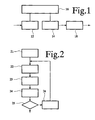
- Figure 1 schematically shows an image processing apparatus, comprising a first image memory 12 for an incoming image, a second image memory 14 for a reconstructed image, a computation unit 16 for updates of the reconstructed image and an output driver 18 for using the reconstructed image to drive a display device (not shown).
- First image memory 12 is coupled to an input of the image processing apparatus. The input may be coupled to a camera (not shown) or other image capturing device.
- Second image memory 14 is coupled to an output of the image processing apparatus via output driver 19.
- Computation unit 16 has inputs coupled to first and second image memory 12, 14 and an output coupled to second image memory 14.
- image processing apparatus 10 receives an incoming image from its input and stores it in first image memory 12.
- Computation unit 16 uses the incoming image in an iterative computation of successive versions of an improved image, or improved image part, and to write these successive versions into second image memory 14.
- the iterative computation aims to minimize a criterion for the improved image, or improved image part.
- the criterion has the following form: Sum ⁇ P ⁇ r - M r 2 + Sum F ( grad P r
- M(r) are the pixel values of the measured image in first image memory 12
- P'(r) are the pixel values determined from the improved image P or improved image part in second image memory 14
- grad P(r) is a gradient vector of the pixel values of the improved image.
- the gradient vector may have components determine from to differences between the pixel value P(r) at the pixel location and pixel values at adjacent pixel locations in different directions, but instead a more complex filter function may be used to determine the gradient.
- the sums are taken over pixel locations "r" (the first and second sum are not necessarily taken over the same sets of pixel locations: when P has higher resolution than M, the second sum may involve more pixel locations, for example).
- Both the function F and its derivative vary continuously as a function of its argument. Continuous variation of a function over a range of argument values means that the variation decreases with decreasing size of the range and that for any small but non-zero variation a corresponding finite range can be indicated wherein the variation is smaller than that small but non-zero variation.
- F(x) x 2
- F(x)
- F(x) has quadratic and linear asymptotic behaviour for small amplitude of "x" and for large amplitude respectively. Hence it asymptotically behaves like the L2 norm for small gradients and like the L1 norm for large gradients.
- the derivative of this function c*(sqrt(x 2 +a 2 )-a) is bounded, in contrast to the derivative of the L2 norm, which grows indefinitely in proportion to x. This results in better preservation of edges.
- two argument regimes of behaviour of the function may be distinguished.
- the first regime covers an interval with small gradient values, including zero gradient, with a size significantly less than the parameter value "a”.
- the second regime covers large gradient values, with a size significantly larger than the parameter value "a”.
- the function has a minimum (zero derivative) for zero size gradient and the first derivative increases gradually for gradients of increasing size.
- the changes of the derivative are approximately evenly distributed over the interval with small gradient values, in contrast to the L1 norm, where the change of derivative occurs only for zero measure of variation. This results in improved convergence properties for the iteration.
- the first derivative In the second regime the first derivative has little variation, because the function approaches an asymptotically linear behaviour.
- the parameter "a" that determines the size of the gradient at the transition between the two regimes may be selected dependent on noise amplitude, In an embodiment the parameter "a” is set to a value between the standard deviation of the noise and ten times the standard deviation, so that F behaves according to its small amplitude regime for the majority of the noise and according to its large amplitude regime for outliers.
- the parameter "c” determines the relative weights given to getting a regularized image and to faithfulness to the incoming image M.
- the value of the parameter "c” may be chosen dependent on the application of the improved image P, with a lower value of a sharp but noisier improved image is needed and a higher value if a less noisy but also less sharp image is needed.
- Computation unit 16 need not actually compute the value of the criterion. In an embodiment it suffices to compute derivatives of the criterion with respect to variations of the pixel values P(r) of the improved image. These derivatives may take the form 2 * Sum ⁇ P r - M r + Sum F ⁇ grad P r ⁇ * D r ⁇ r ⁇
- D(r,r') is the derivative of the gradient with respect to P(r) for those pixel locations r' where the gradient depends on P(r) (typically the pixel location r and a number of surrounding locations). The sum is taken over those pixel locations r'.
- the term in the sum is non linear function of the pixel values of the improved image P(r), because F is not a linear function.
- the function serves to give different weights to gradients of different size. For large gradients the term in the sum becomes independent of the gradient and for small gradients it is becomes approximately linear in the gradient. Thus, the relative weight of different gradients is changed.
- the improved image P may have a higher resolution than the incoming image M.
- the incoming image M(r') may be compared with a filtered and sub-sampled version P' (r") of the improved image.
- the derivatives with respect to the improved pixel values P(r) take the form 2 * Sum ⁇ P ⁇ r " - M r ⁇ * Q r , r " + Sum F ⁇ grad P r ⁇ * D r ⁇ r ⁇
- the sums are taken over the locations r' and r".
- at least the term in the sum is non linear function of the pixel values of the improved image P(r), because F is not a linear function.
- computation unit 16 iteratively selects successive iterations of improved image values using Levenberg-Marquardt optimization.
- Levenberg-Marquardt optimization provides for finding parameters that minimize a function of the type V*V, wherein V is a vector or components that depend on a vector of the parameters x whose values must be found.
- the parameters x are the image values P(r).
- the condition for the minimum can be expressed in terms of a Jacobian matrix J, with derivatives dVi/dx of the components Vi of the vector V with respect to the parameters x.
- V en J depend on the parameters x.
- the Jacobian J and the vector depend on the parameter vector x of the iteration. In other words, in each iteration a delta is selected that minimizes a quadratic function (delta*J+V)2+lambda*delta 2 .
- the vector V is expanded with additional components that are square roots of the regularization terms.
- the vector will have a first set of components V1 that represent deviations from observed values M(r) and a second set of components V2 with square roots of regularization functions sqrt(F(grad P(r))).
- V1*J1 represents a sum over the first set of vector components, that is over locations in the measured signal, summing products of vector components and derivatives.
- J1 T J1 represents a sum of products of derivatives over that range.
- V2*J2 represents a sum of vector components and derivatives over the second set of vector components, that is over locations for which regularization terms are used.
- J2 T J2 represents a sum of products of derivatives over that range.
- the problem can be solved by other functions that have the same property.
- the derivative F' of the regularization function divided by the square root of the regularization function should have a finite non zero value, also in the limit where the gradient of the reconstructed image approaches zero.
- Figure 2 shows a flow-chart of an exemplary algorithm for computing the improved image P or sub-image that is a part of a larger image.
- computation unit 16 selects an initial version of the improved image P or sub-image that is a part of a larger image.
- An image with position independent pixel values may be used for example, or the result of previous processing may be used.
- computation unit 16 computes the derivatives according to the expression discussed above, using the pixel values of the incoming image M(r) and the current version of the improved image P.
- the convergence factor lambda may be set differently in different iterations.
- computation unit 16 adds the updates "delta" to the current version of the improved image P or sub-image that is a part of a larger image, thus producing a next version of the improved image, or sub-image that is a part of a larger image.
- computation unit 16 tests whether a convergence criterion is satisfied. A simple criterion may be to test whether a predetermined number of iterations has been performed, but alternatively a measure of convergence computed from the derivatives may be compared with a threshold value. In this case fifth step could be performed before third step 23. If the convergence criterion is satisfied, computation unit 16 terminates the iterative process and delivers the improved image.
- computation unit 16 executes a sixth step 26, preparing a next iteration, for example by adjusting the factor to be used in third step 23, after which computation unit 16 repeats from second step 22 (when fifth step 25 is performed before third step 23 sixth step 26 may be executed after fourth step 24).
- the algorithm of figure 2 is only one example of an algorithm for determining successive versions of the improved image based on the quality criterion that uses the function F.
- Other examples may include conjugate gradient optimization, etc.
- use of a Levenberg-Marquardt type algorithm increases the speed of convergence.
- the function reduces the risk that the iteration process gets trapped in a local minimum, so that the initial image used in the iterations has a strong effect on the improved image.
- F(x)
- the risk of trapping is reduced already when the value of the parameter "a" is significantly larger (say at least three times larger) than the rounding error of the computation used to compute updates of the improved image.
- a higher value of the parameter "a” improves the speed of convergence and further reduces the risk of trapping.
- a lower limit of the value of the parameter is set in proportion with the iteration step size. This improves concergence speed.
- the value of the parameter is set proportional to an input indicating the minimum size of the steps that that should be reconstructed. In another embodiment such an input may be used to set an upper limit for the parameter.
- the value of the parameter is set dependent on image noise produced by the source of the image, to a value of at least three times the standard deviation of the image noise and an upper limit less than one third of the smallest size edge that has to be reconstructed.
- the parameter is set to an upper or lower limit if the value derived from the noise is past the upper or lower limit.
- a computation unit 16 is configured to determine an estimated noise amplitude of the incoming image. However, it is not necessary to use the image itself to estimate the noise amplitude, instead the noise amplitude of a further image or images of a series of images of which the incoming image is part may be estimated.
- the value of the parameter "a" is set dependent on the estimated noise amplitude, for example to at least three times the estimated noise amplitude.
- the noise amplitude may be estimated from a spread of pixel values in an image segment without detected edges. This may be used to improve the speed of convergence.
- F( ⁇ grad P(r) ⁇ ) F( ⁇ grad P(r) ⁇ ).
- F(x) c*(sqrt(x 2 +a 2 )-a), which asymptotically grows in proportion to the absolute value of x for large x
- a different function may be used that grows more slowly for large x.
- a function that saturates at a finite value for large x may be used.
- Any continuously varying function F may be used that has a bounded derivative and approximately evenly distributed changes of its first derivative in an interval of small gradient sizes, from zero derivative at zero gradient wherein most of the changes of the derivative of F are concentrated.
- the bounded value of the derivative means that the derivative of the regularization function levels off somewhere in the range of possible gradient values (say by reaching a derivative value more than ninety percent of the maximum possible derivative at a measure of variation that is a fraction of the maximum possible measure of variation, say less than half that maximum possible measure of variation).
- the second derivative a 2 /(x 2 +a 2 ) 3/2 has a non-zero value everywhere, exceeding a fraction of half of the constant derivative 1/a*sqrt(2) needed to provide the total variation from 0-1/sqrt(2) of the derivative in the interval.
- the interval in which the change of the derivative of the regularization function is concentrated should preferably contain the gradient values of the improved image that are due to rounding errors in the computation of the improved image and more preferably this interval should contain a significant part of the noise in the gradient due to noise (or signal variation in regions without relevant edges) in the incoming image. This improves convergence.
- a signal processing method for generating a reconstructed, location dependent signal, comprising
- a regularization function may be used that varies in proportion to a difference between a square root of a sum of a square of the measure of variation plus a square of a parameter.
- a regularization function may be used that concentrates measure of variation dependent changes in the derivate of the regularization function in an interval of values of the measure of variation.
- the method may comprise comprising receiving an input indicating a minimum step size that should be reconstructed and setting the size of said interval dependent on said input. This may be done for example by adapting the scale factor of the argument of the function.
- the interval preferably contains at least the standard deviation of the effect of noise in the incoming signal on the measure of variation.
- the noise amplitude of the signal, or of at least one further signal in a series of signals that comprises the signal is measured and the regularization function is adapted (e.g. it scale factor is adapted) to set the size of the interval dependent on the measured noise amplitude.
- the signal processing method is applied to reconstruct an image signal from an incoming image signals.
Landscapes
- Physics & Mathematics (AREA)
- General Physics & Mathematics (AREA)
- Engineering & Computer Science (AREA)
- Theoretical Computer Science (AREA)
- Image Processing (AREA)
Abstract
Description
- The invention relates to an apparatus and method that uses incoming signals to produce improved quality signals, such as improved image signals with position dependent pixel values.
- For image handling equipment such as camera's, television sets, image recording and image replay equipment it is desirable to produce improved quality images from incoming or stored images. Quality improvements may include increasing the resolution of the images, suppressing noise etc. One known quality improvement technique is called image reconstruction and involves searching for an improved image that results in a quality optimization according to a quality criterion expressed in terms of a sum of differences between pixel values of the incoming image and pixel values of the improved image plus a so-called regularization function. The quality criterion may take the form

Herein the sum is taken over the pixel positions "r" in the incoming image M that are used to improve the improved image P. R is the regularization function, which depends on a set of values of the improved image P(r) for different pixel positions "r". M(r) are pixel values of the incoming image and P'(r) are pixel values of a version of the improved image that is used for comparison. In many applications P'(r) may equal P(r), but for example when the improved image P(r) has a higher resolution than the incoming image M, P'(r) may be a filtered and subsampled version of P(r). - The regularization function is often needed because the improved information P(r) contains more information (has more degrees of freedom) than the incoming image M(r), with the result that the task of construction of the improved image P(r) is ill posed. The regularization function provides for a criterion for optimal use of the additional degrees of freedom.
- In known image reconstruction techniques the regularization function has been implemented as a sum of squares of total variation values for pixel locations in the improved image, summed over pixel locations in the improved image. The square of the total variation at a pixel location may be taken as the square of the gradient vector of the pixel values at that pixel location. However, this type of regularization function has been found to have the disadvantage that it is not robust to outliers (e.g. strongly erroneous pixel values in the incoming image) and that it has an unnecessarily smoothing effect on the improved image.
- As an improvement has been suggested to implement the regularization function using a sum of absolute values of the total variation values for pixel locations in the improved image, instead of a sum of squares. This makes image reconstruction more robust against outliers, as the absolute value does not increase as strongly as the square. However, it has been found that this selection of the regularization function may still lead to sub-optimal reconstruction. A similar problem has been found when reconstruction is applied to sound signals,
- Construction of a tomographic volume model is described in an article titeld "Modeling anisotropic undersampling of magnetic resonance angiographies and reconstruction of a high-resolution isotropic volume using half-quadratic regularization techniques", by E. Roullot et al, published in Signal Processing, Elsevier, vol 84 no 4, pages 743-762, 2004 (EPO reference XP4495319). Roullot et al propose to use a conjugate gradient algorithm to search for an optimally reconstructed model. The conjugate gradient algorithm works well when it is used to optimize a function that nearly has a quadratic form. Roullot et al propose to use the so-called Huber function as a regularization function. The Huber function is a parabolic function of its argument for values of the argument that have a size of below a threshold value and a linear extension of this parabolic function for argument values of larger size.
- The conjugate gradient algorithm that is used by Roullot et al has a limited speed of convergence. The optimization problem formulated by Roullot et al does not comply with the type of problem that is required by algorithms that provide for faster convergence, such as the Levenberg-Marquardt algorithm.
- Construction of a tomographic volume model is also disclosed in an article titled "Constrained Total Variation Minimization and Application in Computerized Tomography" by Xiao-Qun Zhang et al, published in Energy minimization methods in computer vision and pattern recognition lecture notes in computer science, Springer, volume 3757, January 2005, pages 456-472 (EPO reference XP19024154) Zhang et al discuss minimization of total variation, giving a definition of total variation as a square root of a sum of a a square of the gradient of the reconstructed signal and a constant. As may be noted this function is not zero when the gradient is zero. Zhang et al propose to use a gradient descent algorithm.
- The gradient descent algorithm that is used by Zhang et al has a limited speed of convergence. The optimization problem formulated by Zhang et al does not comply with the type of problem that is required by algorithms that provide for faster convergence, such as the Levenberg-Marquardt algorithm.
- Another tomographic model construction method is disclosed in an article titled "Three-dimensional edge-preserving image enhancement for computed tomography" by M. Villain et al, published in the IEEE transactions on medical imaging, (EPO reference XP11101826). Villain et al. use quadratic optimalization. They propose to use of a quadratic regularization function. No conditions are imposed on the value of the regularization function at the argument for which its derivative is zero. The optimization problem formulated by Villain et al. does not comply with the type of problem that is required by algorithms that provide for fast convergence, such as the Levenberg-Marquardt algorithm.
- The Levenberg-Marquardt algorithm is an example of an algorithm that uses an iteration process for solving an equation that a scalar product V*J=0 of a vector V and a derivative J of that vector V with respect to the reconstructed signal is zero. Conventionally, the vector V comprises vector components (M(r)-P(r)) corresponding to differences between values M(r) of a measured signal and predictions P(r) of the measured signal values derived from the reconstructed signal.
- The iteration process of Levenberg-Marquardt uses a matrix JTJ that is a scalar product of derivatives J of the vector V (JT is the transpose of J). For small changes "delta" of the reconstructed signal, the effect of the changes on the scalar product V*J can be approximated linearly by (V0+delta*JT)J, where V0 and J have their values without accounting for the change delta. This can be used to determine iterative updates "delta". The Levenberg-Marquardt algorithm does so by solving delta from an equation delta*(JTJ+lambda)= -V*J. Herein a convergence control term "lambda" has been added (notionally multiplied by a unit matrix), which does not affect the solution when V*J=0. The term lambda may be adapted arbitrarily without affecting the solution. Lambda may be set to zero. In this case, one obtains the Gauss-Newton algorithm.
- In order for the iteration process to work, it is of course necessary that the components of the vector V depend on the reconstructed signal, i.e. that their derivatives with respect to the reconstructed signal are not zero. This is ensured by using components of the type (M(r)-P(r)) corresponding to differences between values M(r) of a measured signal and predictions P(r) of the measured signal values derived from the reconstructed signal. However, the Levenberg-Marquardt algorithm does not provide for a regularization.
- Regularization could be introduced in the Levenberg-Marquardt algorithm by expanding the optimalization criterion with a sum of squares of total variation values for pixel locations in the improved image, summed over pixel locations in the improved image. In the Levenberg-Marquardt algorithm this results in added components of the vector V that are proportional to the gradients. However this has the above-described disadvantage that it is not robust to outliers and that it has an unnecessarily smoothing effect on the improved image.
- Among others, it is an object to provide for better improvement of signal quality, wherein a more quickly converging algorithm such as the Levenberg-Marquardt algorithm can be used to search for the reconstructed signal.
- A signal processing method according to claim 1 is provided. Herein an incoming signal such as an image signal or a seismic signal for example, is used to compute a reconstructed signal. An iterative computation such as the Levenberg-Marquardt algorithm is used, wherein the vector V comprises second vector components V2 that are square roots of values obtained by applying a regularization function to measures of variation of the reconstructed signal as a function of the location.
- For the regularization function a function is used that has a derivative of bounded size that varies continuously as a function of the measure of variation from zero at zero measure of variation.
- In this way it is ensured that the vector components remain sensitive to changes in the reconstructed signal, while at the same time preventing undue effects of outliers.
- A regularization function that varies proportionally to sqrt ( [grad P(r)]2 + a2 )-a may be used for example, wherein P(ris the reconstructed signal and "a" is a parameter. For argument values grad I(r) with a size higher than the parameter "a" asymptotically linear variation is realized, so that the derivatives are bounded by zero and its asymptotic values. For argument values grad I(r) with a size lower than the parameter value "a" a continuous approximately square dependence on the size of grad I(r) is realized, with a derivative that goes to zero smoothly.
- The use of a regularization function with bounded derivatives has been found to improve reconstruction of edges in the improved signal. In this way edge reconstruction problems are reduced compared with a quadratic regularization function of grad I(r). The gradual reduction of the derivative for small values of the measure of variation of the reconstructed image has been found to improve robust convergence to a unique improved image. In this way convergence problems with a function proportional to the absolute size of grad I(r), which would result in concentration of the entire change of the derivative at zero gradient of the reconstructed image, are prevented.
- More generally, these advantages occur when the derivative of the regularization function with respect to the measure of variation is bounded and a regularization function is of a type wherein changes of the derivative of the function are concentrated at values of the measure of variation that are distributed over a finite interval of small values of the measure of variation. In the case of the function sqrt ( [grad I(r)]2 + a2 )-a for example, the interval is defined by the parameter "a". Given a percentage of change in the derivative over the entire range of arguments of the function, a finite interval proportional to "a" inherently follows that contains this percentage of the change. The finite interval with concentrated locations may be defined as the interval that comprises zero measure of variation, and in which a significant fraction, say at least one half, of the variation of the derivative of the regularization function occurs. Distribution of the change of derivative over this finite interval occurs when at all locations in the interval, or at least at a majority of the locations, the second derivative of the regularization function exceeds a finite minimum value that is not excessively less than (say not less than one tenth, and more preferably not less than half) a constant second derivative that would be required to account for the total change of the derivative in the interval. In the case of the regularization function sqrt ( [grad I(r)]2 + a2 )-a, the value of the parameter "a" determines the size of this interval.
- In an embodiment the size of the interval wherein the change of the derivative of the regularization function is concentrated, i.e. if applicable the value of the parameter "a", is selected dependent on noise in the incoming signal. Thus the argument of the regularization function is scaled. In a further embodiment a size of this noise is estimated and the estimation is used to set the sizes of the interval, i.e. to adapt the scale factor of the argument of the regularization function, so that the interval contains at least a significant part of the noise, e.g. by setting the parameter "a" dependent on the noise amplitude, for example to three times the standard deviation of the noise in the gradient.
- These and other objects and advantages will become apparent from a description of exemplary embodiments, using the following figures.
-
Figure 1 shows an image processing apparatus -
Figure 2 shows a flow-chart of an algorithm for selecting changes of pixel values -
Figure 1 schematically shows an image processing apparatus, comprising afirst image memory 12 for an incoming image, asecond image memory 14 for a reconstructed image, acomputation unit 16 for updates of the reconstructed image and anoutput driver 18 for using the reconstructed image to drive a display device (not shown).First image memory 12 is coupled to an input of the image processing apparatus. The input may be coupled to a camera (not shown) or other image capturing device.Second image memory 14 is coupled to an output of the image processing apparatus via output driver 19.Computation unit 16 has inputs coupled to first andsecond image memory second image memory 14. - In operation image processing apparatus 10 receives an incoming image from its input and stores it in
first image memory 12.Computation unit 16 uses the incoming image in an iterative computation of successive versions of an improved image, or improved image part, and to write these successive versions intosecond image memory 14. - The iterative computation aims to minimize a criterion for the improved image, or improved image part. In an embodiment, the criterion has the following form:

- Herein M(r) are the pixel values of the measured image in
first image memory 12, P'(r) are the pixel values determined from the improved image P or improved image part insecond image memory 14 and grad P(r) is a gradient vector of the pixel values of the improved image. The gradient vector may have components determine from to differences between the pixel value P(r) at the pixel location and pixel values at adjacent pixel locations in different directions, but instead a more complex filter function may be used to determine the gradient. - The sums are taken over pixel locations "r" (the first and second sum are not necessarily taken over the same sets of pixel locations: when P has higher resolution than M, the second sum may involve more pixel locations, for example).
- Both the function F and its derivative vary continuously as a function of its argument. Continuous variation of a function over a range of argument values means that the variation decreases with decreasing size of the range and that for any small but non-zero variation a corresponding finite range can be indicated wherein the variation is smaller than that small but non-zero variation.
- In an embodiment the function F applied to a symbolic vector variable x =(grad P(r)) takes the form

wherein a and c are parameters and sqrt is the square root function. This function should be contrasted with the conventional L2 norm, wherein F(x)= x2 and the conventional L1 norm wherein F(x)= |x|. As may be noted F(x) has quadratic and linear asymptotic behaviour for small amplitude of "x" and for large amplitude respectively. Hence it asymptotically behaves like the L2 norm for small gradients and like the L1 norm for large gradients. - It should be noted that the derivative of this function c*(sqrt(x2+a2)-a) is bounded, in contrast to the derivative of the L2 norm, which grows indefinitely in proportion to x. This results in better preservation of edges. Furthermore it should be noted that two argument regimes of behaviour of the function may be distinguished. The first regime covers an interval with small gradient values, including zero gradient, with a size significantly less than the parameter value "a". The second regime covers large gradient values, with a size significantly larger than the parameter value "a". In the interval with small gradient values, the function has a minimum (zero derivative) for zero size gradient and the first derivative increases gradually for gradients of increasing size. Thus, the changes of the derivative are approximately evenly distributed over the interval with small gradient values, in contrast to the L1 norm, where the change of derivative occurs only for zero measure of variation. This results in improved convergence properties for the iteration. In the second regime the first derivative has little variation, because the function approaches an asymptotically linear behaviour.
- The parameter "a" that determines the size of the gradient at the transition between the two regimes may be selected dependent on noise amplitude, In an embodiment the parameter "a" is set to a value between the standard deviation of the noise and ten times the standard deviation, so that F behaves according to its small amplitude regime for the majority of the noise and according to its large amplitude regime for outliers.
- The parameter "c" determines the relative weights given to getting a regularized image and to faithfulness to the incoming image M. The value of the parameter "c" may be chosen dependent on the application of the improved image P, with a lower value of a sharp but noisier improved image is needed and a higher value if a less noisy but also less sharp image is needed.
-
Computation unit 16 need not actually compute the value of the criterion. In an embodiment it suffices to compute derivatives of the criterion with respect to variations of the pixel values P(r) of the improved image. These derivatives may take the form
Herein D(r,r') is the derivative of the gradient with respect to P(r) for those pixel locations r' where the gradient depends on P(r) (typically the pixel location r and a number of surrounding locations). The sum is taken over those pixel locations r'. - It should be noted that at least the term in the sum is non linear function of the pixel values of the improved image P(r), because F is not a linear function. The function serves to give different weights to gradients of different size. For large gradients the term in the sum becomes independent of the gradient and for small gradients it is becomes approximately linear in the gradient. Thus, the relative weight of different gradients is changed.
- In another embodiment, the improved image P may have a higher resolution than the incoming image M. In this case the incoming image M(r') may be compared with a filtered and sub-sampled version P' (r") of the improved image. Setting the derivative of a pixel value of this version P' (r") with respect to the pixel value of the improved image P(r) equal to Q(r,r"), the derivatives with respect to the improved pixel values P(r) take the form

Herein the sums are taken over the locations r' and r". Again it should be noted that at least the term in the sum is non linear function of the pixel values of the improved image P(r), because F is not a linear function. - In an
embodiment computation unit 16 iteratively selects successive iterations of improved image values using Levenberg-Marquardt optimization. As is known per se Levenberg-Marquardt optimization provides for finding parameters that minimize a function of the type V*V, wherein V is a vector or components that depend on a vector of the parameters x whose values must be found. In the present case the parameters x are the image values P(r). The condition for the minimum can be expressed in terms of a Jacobian matrix J, with derivatives dVi/dx of the components Vi of the vector V with respect to the parameters x. The problem of finding an optimal set of parameters x can be expressed as a derivative equation V*J=0. Herein V en J depend on the parameters x. - The Levenberg-Marquardt algorithm and more special techniques such as Gauss-Newton provide for iterative updates of the parameter values to converge to a solution of the equation V*J=0. In the case of the Levenberg-Marquardt algorithm for example, the update "delta" to the parameter vector in an iteration is computed as a solution of the equation delta*(JTJ+lambda*I) = -V*J, wherein JT is the transpose of J, lambda is a control parameter and I is a unit matrix with the same dimensions as the product matrix JTJ. Here the Jacobian J and the vector depend on the parameter vector x of the iteration. In other words, in each iteration a delta is selected that minimizes a quadratic function (delta*J+V)2+lambda*delta2.
- In the present case, where added regularization terms are used, the vector V is expanded with additional components that are square roots of the regularization terms. Thus the vector will have a first set of components V1 that represent deviations from observed values M(r) and a second set of components V2 with square roots of regularization functions sqrt(F(grad P(r))). The Jacobian has components Jl=dV1/dP(r) and J2=dV2/dP(r) so that the equation for the minimum is V1*J1+V2*J2=0. In the case of the Levenberg-Marquardt algorithm for example, the update "delta" to the parameter vector in an iteration is computed as a solution of the set of equations

Here V1*J1 represents a sum over the first set of vector components, that is over locations in the measured signal, summing products of vector components and derivatives. J1TJ1 represents a sum of products of derivatives over that range. V2*J2 represents a sum of vector components and derivatives over the second set of vector components, that is over locations for which regularization terms are used. J2TJ2 represents a sum of products of derivatives over that range. - In the case of image reconstruction the first set of components is defined by V1(r)=P(r)-M(r), or V1(r)=P'(r)-M(r) in the case of a higher resolution image P(r), and the second set of components is defined by V2(r)=sqrt(F(grad P(r)). When only a sub-image is reconstructed that is part of a larger image, these vector components are only needed for pixel locations in the sub-image or in the sub-image and band of the larger image that surrounds it. The corresponding components of the Jabobian for V1 are dV1(r1)/dP(r2)=1 if the pixel locations r1 and r2 are equal and zero otherwise, or

in the case of a higher resolution image. The corresponding components of the Jabobian for V2 are
However, iterative techniques for solving the equation V1*J1+V2*J2=0 in this case have been found to work only if the regularization function F has zero value at argument values where its derivative is zero. Otherwise, the second set of vector components V2(r) would depend on the parameters in a way that makes the second set of vector components insensitive to small changes in the parameter values P(r), where there are no gradients. This would prevent stable convergence. The function F(x)=c*(sqrt(x2+a2)-a) is an example of a function that ensures that this does not occur, because it is zero at the value x=0 for which its derivative c*x/ sqrt(x2+a2) is zero. It has been found that this facilitates convergence in an iterative way to the solution of the equation V1*J1+V2*J2=0. Alternatively, the problem can be solved by other functions that have the same property. Preferably, the derivative F' of the regularization function divided by the square root of the regularization function should have a finite non zero value, also in the limit where the gradient of the reconstructed image approaches zero. -
Computation unit 16 may use other known strategies to select successive versions of the improved image. For example, a set of changes of respective pixel values may be selected in proportion to the derivatives for those pixel values, or at least dependent on the derivatives. However, many of these other techniques do not provide for the same speed of convergence as the iterative solutions of the equation V*J=0. -
Figure 2 shows a flow-chart of an exemplary algorithm for computing the improved image P or sub-image that is a part of a larger image. In afirst step 21computation unit 16 selects an initial version of the improved image P or sub-image that is a part of a larger image. An image with position independent pixel values may be used for example, or the result of previous processing may be used. In asecond step 22,computation unit 16 computes the derivatives according to the expression discussed above, using the pixel values of the incoming image M(r) and the current version of the improved image P. In athird step 23,computation unit 16 computes the vector of update values "delta" for the improved image P by solving the equation delta*(J1TJ1+ J2TJ2+lambda*I) = -V1*J1-V2*J2 for "delta" based on the computed derivatives. The convergence factor lambda may be set differently in different iterations. - In a
fourth step 24,computation unit 16 adds the updates "delta" to the current version of the improved image P or sub-image that is a part of a larger image, thus producing a next version of the improved image, or sub-image that is a part of a larger image. In afifth step 25,computation unit 16 tests whether a convergence criterion is satisfied. A simple criterion may be to test whether a predetermined number of iterations has been performed, but alternatively a measure of convergence computed from the derivatives may be compared with a threshold value. In this case fifth step could be performed beforethird step 23. If the convergence criterion is satisfied,computation unit 16 terminates the iterative process and delivers the improved image. If the convergence criterion is not satisfied,computation unit 16 executes asixth step 26, preparing a next iteration, for example by adjusting the factor to be used inthird step 23, after whichcomputation unit 16 repeats from second step 22 (whenfifth step 25 is performed beforethird step 23sixth step 26 may be executed after fourth step 24). - It should be emphasized that the algorithm of
figure 2 is only one example of an algorithm for determining successive versions of the improved image based on the quality criterion that uses the function F. Other examples may include conjugate gradient optimization, etc. However, use of a Levenberg-Marquardt type algorithm increases the speed of convergence. The use of an optimization criterion of the form
combined with a regularization function F of the form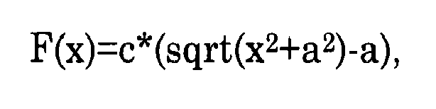
Has the effect that edges in the image, for example at transitions between pixel locations foreground objects and background are imaged, will be better preserved than when a function F(x)=x2 is used that increases more rapidly for large values of x. By selecting the value of the parameter "a" smaller than the smallest step size of the edges that should be reconstructed, for example at least three times smaller, the sharpness of these edges is preserved. - On the other hand, the function reduces the risk that the iteration process gets trapped in a local minimum, so that the initial image used in the iterations has a strong effect on the improved image. Compared to a function F(x) = | x | the risk of trapping is reduced already when the value of the parameter "a" is significantly larger (say at least three times larger) than the rounding error of the computation used to compute updates of the improved image. A higher value of the parameter "a" improves the speed of convergence and further reduces the risk of trapping.
- In an embodiment a lower limit of the value of the parameter is set in proportion with the iteration step size. This improves concergence speed.
- In an embodiment the value of the parameter is set proportional to an input indicating the minimum size of the steps that that should be reconstructed. In another embodiment such an input may be used to set an upper limit for the parameter.
- In an embodiment the value of the parameter is set dependent on image noise produced by the source of the image, to a value of at least three times the standard deviation of the image noise and an upper limit less than one third of the smallest size edge that has to be reconstructed. Optionally, the parameter is set to an upper or lower limit if the value derived from the noise is past the upper or lower limit. In a further embodiment, a
computation unit 16 is configured to determine an estimated noise amplitude of the incoming image. However, it is not necessary to use the image itself to estimate the noise amplitude, instead the noise amplitude of a further image or images of a series of images of which the incoming image is part may be estimated. The value of the parameter "a" is set dependent on the estimated noise amplitude, for example to at least three times the estimated noise amplitude. In a further embodiment the noise amplitude may be estimated from a spread of pixel values in an image segment without detected edges. This may be used to improve the speed of convergence. - It should be noted that various alternatives are possible for the term F( { grad P(r)}). For example one may use a function F(x)=x2/2a if abs(x)<a and F(x)=abs(x)-a/2 if abs(x)>a, or a weighted function of x2/2a and abs(x)-a/2 with weights that gradually vanish for absolute values abs(x) of the argument x above and below "a" respectively. As another example, instead of the function F(x)=c*(sqrt(x2+a2)-a), which asymptotically grows in proportion to the absolute value of x for large x, a different function may be used that grows more slowly for large x. For example, a function that saturates at a finite value for large x may be used. By keeping the growth of F(x) for large x limited to linear growth or less, edges in the incoming image M(r) can be better preserved.
- Similarly, various alternatives exist for the small argument behaviour of the function F. For example, a function

may be used. Any continuously varying function F may be used that has a bounded derivative and approximately evenly distributed changes of its first derivative in an interval of small gradient sizes, from zero derivative at zero gradient wherein most of the changes of the derivative of F are concentrated. The bounded value of the derivative means that the derivative of the regularization function levels off somewhere in the range of possible gradient values (say by reaching a derivative value more than ninety percent of the maximum possible derivative at a measure of variation that is a fraction of the maximum possible measure of variation, say less than half that maximum possible measure of variation). - These changes of the derivative of the regularization function should occur concentrated in an interval of low gradient values of the improved image and distributed over that at least with a minimum amount of homogeneity over that interval, in the sense that in a significant part of the interval (say in at least half that interval) the size of the second derivative of the function is greater than a level proportional to the total variation of the size of the derivative in the low range from zero to its maximum size. The level may be equal to a tenth of a constant value of the second derivative that would be needed to account for the total variation in the interval. For example, in the case of F(x)=sqrt (x2+a2)-a, the derivative is x/sqrt (x2+a2) which levels off to one for increasing x, so that the change of the derivative is concentrated in an interval determined by the parameter "a" (e.g. a fraction of 1/sqrt(2) > 70% of the variation of the derivative is concentrated in the interval 0=x-a). In this interval the second derivative a2/(x2+a2)3/2 has a non-zero value everywhere, exceeding a fraction of half of the constant derivative 1/a*sqrt(2) needed to provide the total variation from 0-1/sqrt(2) of the derivative in the interval.
- As mentioned the interval in which the change of the derivative of the regularization function is concentrated should preferably contain the gradient values of the improved image that are due to rounding errors in the computation of the improved image and more preferably this interval should contain a significant part of the noise in the gradient due to noise (or signal variation in regions without relevant edges) in the incoming image. This improves convergence.
- Although a function F dependent on the gradient grad(P(r)) has been used, it should be understood that other dependencies on the pixel values of the improved image may be used. For example, a function of the Laplacian instead of the gradient may be used. As long as the term with the function f adds weight against unnecessary variation of P(r) as a function of pixel position, limits the weight assigned to large (edge-related) variation and varies continuously in a range of values corresponding to noise any term may be used.
- Although an example has been given for a simple optimization criterion,

it should be understood that a more complex criteria may be used. For example a term f*Sum[ (P(r)-Po(r))2 ] may be added, when the incoming images is used to augment an initial image Po. The initial image may have been obtained using previously received incoming images. - Although an application to an iterative image reconstruction has been shown, it should be realized that alternatively other signals, a video signal, wherein P depends on both position and time, or a three dimensional signal such as a tomographic image signal, or audio signals may be improved or a time dependence of image signals can be improved in this way.
- In an embodiment a signal processing method is used for generating a reconstructed, location dependent signal, comprising
- receiving an incoming signal represented by a set of signal values;
- iteratively computing successive versions of the reconstructed signal, guided by quality improvement according to a quality criterion for said versions that depends on aggregated differences between signal values of the incoming signal and corresponding signal values derived from the reconstructed signal added to a regularization function applied to a measure of variation of the reconstructed signal as a function of the location,
- wherein the regularization function has a derivative of bounded size that varies continuously as a function of the measure of variation from zero at zero measure of variation.
This provides for better improvement of signal quality.
In an embodiment a signal processing apparatus for generating a reconstructed, location dependent signal is provided, the signal processing apparatus comprising an input for receiving a measured incoming signal, a first image memory region for storing the incoming signal, a second image memory region for storing successive versions of an reconstructed image and a computation circuit, wherein the computation circuit is configured to - iteratively compute successive versions of the reconstructed signal, guided by quality improvement according to a quality criterion for said versions that depends on aggregated differences between signal values of the incoming signal and corresponding signal values derived from the reconstructed signal added to a regularization function applied to a measure of variation of the reconstructed signal as a function of the location,
- wherein the regularization function has a derivative of bounded size that varies continuously as a function of the measure of variation from zero in the case of a zero measure of variation.
- A regularization function may be used that varies in proportion to a difference between a square root of a sum of a square of the measure of variation plus a square of a parameter. A regularization function may be used that concentrates measure of variation dependent changes in the derivate of the regularization function in an interval of values of the measure of variation. In this case the method may comprise comprising receiving an input indicating a minimum step size that should be reconstructed and setting the size of said interval dependent on said input. This may be done for example by adapting the scale factor of the argument of the function. The interval preferably contains at least the standard deviation of the effect of noise in the incoming signal on the measure of variation. In an embodiment the noise amplitude of the signal, or of at least one further signal in a series of signals that comprises the signal, is measured and the regularization function is adapted (e.g. it scale factor is adapted) to set the size of the interval dependent on the measured noise amplitude. In an embodiment the signal processing method is applied to reconstruct an image signal from an incoming image signals.
Claims (14)
- A signal processing method for generating a reconstructed, location dependent signal, using an iteration process for solving an equation that a scalar product of a vector V and a derivative of that vector V with respect to the reconstructed signal is zero, the vector V comprising first vector components V1 corresponding to differences between values of an incoming signal and predictions of the incoming signal values derived from the reconstructed signal and second vector components V2 that are square roots of values obtained by applying a regularization function to measures of variation of the reconstructed signal as a function of the location, the iteration process using a matrix that is a scalar product of derivatives of the vector V, the method comprising- receiving the incoming signal represented by a set of signal values;- executing successive iterations of the iteration process, each iteration comprising solving a respective update of the reconstructed signal from an equation for the respective update, wherein the update occurs in the equation multiplied by the matrix;- wherein the regularization function has a derivative of bounded size that varies continuously as a function of the measure of variation from zero at zero measure of variation.
- A signal processing method according to claim 1, wherein each of the successive iterations comprises solving the respective update from an equation

wherein "delta" denotes the update of the reconstructed signal, J1 denotes a matrix of derivatives of the first vector components with respect to the signals values of the reconstructed signal at a set of locations in the reconstructed signal and J2 is a matrix of derivatives of the second vector components with respect to the signals values of the reconstructed signal at the set of locations in the reconstructed signal, lambda being a freely adjustable parameter, each second vector component corresponding to a term that is a square root of the regularization function of a gradient of the reconstructed signal at a respective different location in the reconstructed signal, the measure of variation being the gradient of the reconstructed signal. - A signal processing method according to claim 1 or 2, wherein the regularization function varies in proportion to a difference between a square root of a sum of a square of the measure of variation plus a square of a parameter.
- A signal processing method according to any one of the preceding claims, wherein the regularization function that is used is a function of a type that concentrates measure of variation dependent changes in the derivative of the regularization function in an interval of values of the measure of variation, the method comprising receiving an input indicating a minimum step size of steps in the signal as a function of location that should be reconstructed and scaling the argument of the regularization function dependent on said input.
- A signal processing method according to any one of the preceding claims, wherein the regularization function that is used is a function of a type that concentrates measure of variation dependent changes in the derivative of the regularization function in an interval of values of the measure of variation that contains at least the standard deviation of the effect of noise in the incoming signal on the measure of variation.
- A signal processing method according to claim 4, comprising measuring the noise amplitude of the signal, or of at least one further signal in a series of signals that comprises the signal, and scaling the argument of the regularization function to set the size of the interval dependent on the measured noise amplitude.
- A signal processing method according to any one of claims 1 to 5, wherein the incoming signal and the reconstructed signal are image signals, representing an image or a part of an image.
- A signal processing apparatus for generating a reconstructed, location dependent signal, using an iteration process for solving an equation that a scalar product of a vector V and a derivative of that vector V with respect to the reconstructed signal is zero, the vector V comprising first vector components V1 corresponding to differences between values of an incoming signal and predictions of the incoming signal values derived from the reconstructed signal and second vector components V2 that are square roots of values obtained by applying a regularization function to measures of variation of the reconstructed signal as a function of the location, the iteration process using a matrix that is a scalar product of derivatives of the vector V, the signal processing apparatus comprising- an input for receiving a measured incoming signal,- a first image memory region for storing the incoming signal,- a second image memory region for storing successive versions of an reconstructed image and a computation circuit, wherein the computation circuit is configured to- execute successive iterations of the iteration process, each iteration comprising solving a respective update of the reconstructed signal from an equation for the respective update, wherein the update occurs in the equation multiplied by the matrix;- wherein the regularization function has a derivative of bounded size that varies continuously as a function of the measure of variation from zero in the case of a zero measure of variation.
- A signal processing apparatus according to claim 8, wherein the regularization function varies in proportion to a difference between a square root of a sum of a square of the measure of variation plus a square of a parameter.
- A signal processing apparatus according to claim 8 or 9, wherein the regularization function that is used is a function of a type that concentrates measure of variation dependent changes in the derivative of the regularization function in an interval of values of the measure of variation, the apparatus having an input for receiving an input indicating a minimum step size of steps in the signal as a function of location that should be reconstructed, the computation circuit being configured to scale the argument of the regularization function dependent on said input to set the size of said interval.
- A signal processing apparatus according to claim 8, wherein the regularization function that is used is a function of a type that concentrates measure of variation dependent changes in the derivative of the regularization function in an interval of values of the measure of variation that contains at least the standard deviation of the effect of noise in the incoming signal on the measure of variation.
- A signal processing apparatus according to claim 11 wherein the computation circuit is configured to estimate the noise amplitude of the incoming signal or of at least one further signal in a series of signals that comprises the signal, and to adapt the regularization function to scale the argument of the regularization function dependent on the measured noise amplitude to set the size of said interval.
- A signal processing apparatus according to any one of claims 8 to 12, comprising an image capturing device coupled to the first memory region for supplying the incoming signal, representing a captured image.
- A computer program product, comprising a program of instructions that, when executed by a programmable computer, will cause the programmable computer to perform the method of any one of claims 1 to 7.
Priority Applications (1)
| Application Number | Priority Date | Filing Date | Title |
|---|---|---|---|
| EP09009694.2A EP2148299B1 (en) | 2008-07-25 | 2009-07-27 | Apparatus and method for producing improved quality signals |
Applications Claiming Priority (2)
| Application Number | Priority Date | Filing Date | Title |
|---|---|---|---|
| EP08161222A EP2148298A1 (en) | 2008-07-25 | 2008-07-25 | Apparatus and method for producing improved quality signals |
| EP09009694.2A EP2148299B1 (en) | 2008-07-25 | 2009-07-27 | Apparatus and method for producing improved quality signals |
Publications (2)
| Publication Number | Publication Date |
|---|---|
| EP2148299A1 true EP2148299A1 (en) | 2010-01-27 |
| EP2148299B1 EP2148299B1 (en) | 2018-07-11 |
Family
ID=39745406
Family Applications (2)
| Application Number | Title | Priority Date | Filing Date |
|---|---|---|---|
| EP08161222A Withdrawn EP2148298A1 (en) | 2008-01-18 | 2008-07-25 | Apparatus and method for producing improved quality signals |
| EP09009694.2A Active EP2148299B1 (en) | 2008-07-25 | 2009-07-27 | Apparatus and method for producing improved quality signals |
Family Applications Before (1)
| Application Number | Title | Priority Date | Filing Date |
|---|---|---|---|
| EP08161222A Withdrawn EP2148298A1 (en) | 2008-01-18 | 2008-07-25 | Apparatus and method for producing improved quality signals |
Country Status (1)
| Country | Link |
|---|---|
| EP (2) | EP2148298A1 (en) |
Families Citing this family (1)
| Publication number | Priority date | Publication date | Assignee | Title |
|---|---|---|---|---|
| CN103839238B (en) * | 2014-02-28 | 2017-02-15 | 西安电子科技大学 | SAR image super-resolution method based on marginal information and deconvolution |
Citations (1)
| Publication number | Priority date | Publication date | Assignee | Title |
|---|---|---|---|---|
| US20080170802A1 (en) * | 2005-04-07 | 2008-07-17 | Inria Institut National De Recherche En Iformationque Et | Device For Processing Raw Images Or Tensor Images |
-
2008
- 2008-07-25 EP EP08161222A patent/EP2148298A1/en not_active Withdrawn
-
2009
- 2009-07-27 EP EP09009694.2A patent/EP2148299B1/en active Active
Patent Citations (1)
| Publication number | Priority date | Publication date | Assignee | Title |
|---|---|---|---|---|
| US20080170802A1 (en) * | 2005-04-07 | 2008-07-17 | Inria Institut National De Recherche En Iformationque Et | Device For Processing Raw Images Or Tensor Images |
Non-Patent Citations (4)
| Title |
|---|
| BOGDAN KWOLEK ED - BARTLOMIEJ BELICZYNSKI ET AL: "Detail-Preserving Regularization Based Removal of Impulse Noise from Highly Corrupted Images", ADAPTIVE AND NATURAL COMPUTING ALGORITHMS; [LECTURE NOTES IN COMPUTER SCIENCE;;LNCS], SPRINGER BERLIN HEIDELBERG, BERLIN, HEIDELBERG, vol. 4432, 11 April 2007 (2007-04-11), pages 599 - 605, XP019093344, ISBN: 978-3-540-71590-0 * |
| BOGDAN KWOLEK ET AL.: "ICANNGA", 2007, article "Detail-Preserving Regularization Baaed Removal of Impulse Noise from Highly Corrupted Images", pages: 599 - 605 |
| STANLEY OSHER ET AL.: "An iterative regularization method for total variation based image restoration", MULTISCALE MODEL SIMULATION, vol. 4, no. 2, 2005, pages 460 - 489, XP002550874, DOI: doi:10.1137/040605412 |
| STANLEY OSHER, MARTIN BURGER, DONALD GOLDFARB, JINJUN XU, WOTAO YIN: "An Iterative Regularization Method for Total Variation-Based Image Restoration", SIAM MULTISCALE MODELING & SIMULATION, vol. 4, no. 2, 2005, pages 460 - 489, XP002550874, Retrieved from the Internet <URL:http://www.caam.rice.edu/~wy1/paperfiles/CU_IEOR_TR05-A4.PDF> [retrieved on 20091016] * |
Also Published As
| Publication number | Publication date |
|---|---|
| EP2148299B1 (en) | 2018-07-11 |
| EP2148298A1 (en) | 2010-01-27 |
Similar Documents
| Publication | Publication Date | Title |
|---|---|---|
| Hielscher et al. | Denoising of crystal orientation maps | |
| US20240127043A1 (en) | Image processing system and medical information processing system | |
| US8861821B2 (en) | Ultrasound diagnosis apparatus | |
| Kobler et al. | Total deep variation: A stable regularization method for inverse problems | |
| US7009623B2 (en) | Image processing apparatus and method, recording medium, and program thereof | |
| Purkait et al. | Super resolution image reconstruction through Bregman iteration using morphologic regularization | |
| US8768069B2 (en) | Image enhancement apparatus and method | |
| US8620109B2 (en) | Image processing apparatus, image processing method and image processing program | |
| KR20130038794A (en) | Method of noise reduction in digital x-ray frames series | |
| US20110211765A1 (en) | Image processing apparatus, image processnig method, and program | |
| CN106127689B (en) | Image and video super-resolution method and device | |
| CN111047544B (en) | Saturated image deblurring method based on nonlinear degradation model | |
| Lee et al. | Noise removal with Gauss curvature-driven diffusion | |
| JP2008146643A (en) | Method of reducing motion blur in motion blurred images, apparatus for reducing motion blur in motion blurred images, and computer embodying a computer program for reducing motion blur in motion blurred images Readable medium | |
| CN102646265B (en) | Image processing equipment and method | |
| US9614999B2 (en) | Image processing apparatus and image processing method with edge enhancement | |
| WO2013094131A1 (en) | Image processing apparatus, image pickup apparatus, image processing method, and image processing program | |
| JP7129169B2 (en) | Image processing device, radiation imaging device, image processing method, and program | |
| Zhang et al. | Impulse noise image restoration using nonconvex variational model and difference of convex functions algorithm | |
| EP4189634B1 (en) | Filter for temporal noise reduction | |
| EP2148299B1 (en) | Apparatus and method for producing improved quality signals | |
| US7706625B2 (en) | Trilateral filter for medical diagnostic imaging | |
| Sadek et al. | A variational model for gradient-based video editing | |
| US12333440B2 (en) | Signal processing apparatus, signal processing system, signal processing method, and computer program product | |
| US10068319B2 (en) | Method for noise reduction in an image sequence |
Legal Events
| Date | Code | Title | Description |
|---|---|---|---|
| PUAI | Public reference made under article 153(3) epc to a published international application that has entered the european phase |
Free format text: ORIGINAL CODE: 0009012 |
|
| AK | Designated contracting states |
Kind code of ref document: A1 Designated state(s): AT BE BG CH CY CZ DE DK EE ES FI FR GB GR HR HU IE IS IT LI LT LU LV MC MK MT NL NO PL PT RO SE SI SK SM TR |
|
| AX | Request for extension of the european patent |
Extension state: AL BA RS |
|
| 17P | Request for examination filed |
Effective date: 20100517 |
|
| 17Q | First examination report despatched |
Effective date: 20100609 |
|
| RAP1 | Party data changed (applicant data changed or rights of an application transferred) |
Owner name: NEDERLANDSE ORGANISATIE VOOR TOEGEPAST- NATUURWETE |
|
| GRAP | Despatch of communication of intention to grant a patent |
Free format text: ORIGINAL CODE: EPIDOSNIGR1 |
|
| INTG | Intention to grant announced |
Effective date: 20180213 |
|
| GRAS | Grant fee paid |
Free format text: ORIGINAL CODE: EPIDOSNIGR3 |
|
| GRAA | (expected) grant |
Free format text: ORIGINAL CODE: 0009210 |
|
| AK | Designated contracting states |
Kind code of ref document: B1 Designated state(s): AT BE BG CH CY CZ DE DK EE ES FI FR GB GR HR HU IE IS IT LI LT LU LV MC MK MT NL NO PL PT RO SE SI SK SM TR |
|
| REG | Reference to a national code |
Ref country code: GB Ref legal event code: FG4D |
|
| REG | Reference to a national code |
Ref country code: CH Ref legal event code: EP |
|
| REG | Reference to a national code |
Ref country code: AT Ref legal event code: REF Ref document number: 1017677 Country of ref document: AT Kind code of ref document: T Effective date: 20180715 |
|
| REG | Reference to a national code |
Ref country code: IE Ref legal event code: FG4D |
|
| REG | Reference to a national code |
Ref country code: DE Ref legal event code: R096 Ref document number: 602009053140 Country of ref document: DE |
|
| REG | Reference to a national code |
Ref country code: FR Ref legal event code: PLFP Year of fee payment: 10 |
|
| REG | Reference to a national code |
Ref country code: NL Ref legal event code: FP |
|
| REG | Reference to a national code |
Ref country code: LT Ref legal event code: MG4D |
|
| REG | Reference to a national code |
Ref country code: AT Ref legal event code: MK05 Ref document number: 1017677 Country of ref document: AT Kind code of ref document: T Effective date: 20180711 |
|
| PG25 | Lapsed in a contracting state [announced via postgrant information from national office to epo] |
Ref country code: NO Free format text: LAPSE BECAUSE OF FAILURE TO SUBMIT A TRANSLATION OF THE DESCRIPTION OR TO PAY THE FEE WITHIN THE PRESCRIBED TIME-LIMIT Effective date: 20181011 Ref country code: FI Free format text: LAPSE BECAUSE OF FAILURE TO SUBMIT A TRANSLATION OF THE DESCRIPTION OR TO PAY THE FEE WITHIN THE PRESCRIBED TIME-LIMIT Effective date: 20180711 Ref country code: GR Free format text: LAPSE BECAUSE OF FAILURE TO SUBMIT A TRANSLATION OF THE DESCRIPTION OR TO PAY THE FEE WITHIN THE PRESCRIBED TIME-LIMIT Effective date: 20181012 Ref country code: LT Free format text: LAPSE BECAUSE OF FAILURE TO SUBMIT A TRANSLATION OF THE DESCRIPTION OR TO PAY THE FEE WITHIN THE PRESCRIBED TIME-LIMIT Effective date: 20180711 Ref country code: BG Free format text: LAPSE BECAUSE OF FAILURE TO SUBMIT A TRANSLATION OF THE DESCRIPTION OR TO PAY THE FEE WITHIN THE PRESCRIBED TIME-LIMIT Effective date: 20181011 Ref country code: AT Free format text: LAPSE BECAUSE OF FAILURE TO SUBMIT A TRANSLATION OF THE DESCRIPTION OR TO PAY THE FEE WITHIN THE PRESCRIBED TIME-LIMIT Effective date: 20180711 Ref country code: SE Free format text: LAPSE BECAUSE OF FAILURE TO SUBMIT A TRANSLATION OF THE DESCRIPTION OR TO PAY THE FEE WITHIN THE PRESCRIBED TIME-LIMIT Effective date: 20180711 Ref country code: PL Free format text: LAPSE BECAUSE OF FAILURE TO SUBMIT A TRANSLATION OF THE DESCRIPTION OR TO PAY THE FEE WITHIN THE PRESCRIBED TIME-LIMIT Effective date: 20180711 Ref country code: IS Free format text: LAPSE BECAUSE OF FAILURE TO SUBMIT A TRANSLATION OF THE DESCRIPTION OR TO PAY THE FEE WITHIN THE PRESCRIBED TIME-LIMIT Effective date: 20181111 |
|
| PG25 | Lapsed in a contracting state [announced via postgrant information from national office to epo] |
Ref country code: LV Free format text: LAPSE BECAUSE OF FAILURE TO SUBMIT A TRANSLATION OF THE DESCRIPTION OR TO PAY THE FEE WITHIN THE PRESCRIBED TIME-LIMIT Effective date: 20180711 Ref country code: ES Free format text: LAPSE BECAUSE OF FAILURE TO SUBMIT A TRANSLATION OF THE DESCRIPTION OR TO PAY THE FEE WITHIN THE PRESCRIBED TIME-LIMIT Effective date: 20180711 Ref country code: HR Free format text: LAPSE BECAUSE OF FAILURE TO SUBMIT A TRANSLATION OF THE DESCRIPTION OR TO PAY THE FEE WITHIN THE PRESCRIBED TIME-LIMIT Effective date: 20180711 |
|
| REG | Reference to a national code |
Ref country code: CH Ref legal event code: PL |
|
| PG25 | Lapsed in a contracting state [announced via postgrant information from national office to epo] |
Ref country code: LU Free format text: LAPSE BECAUSE OF NON-PAYMENT OF DUE FEES Effective date: 20180727 |
|
| REG | Reference to a national code |
Ref country code: BE Ref legal event code: MM Effective date: 20180731 |
|
| REG | Reference to a national code |
Ref country code: DE Ref legal event code: R097 Ref document number: 602009053140 Country of ref document: DE |
|
| PG25 | Lapsed in a contracting state [announced via postgrant information from national office to epo] |
Ref country code: MC Free format text: LAPSE BECAUSE OF FAILURE TO SUBMIT A TRANSLATION OF THE DESCRIPTION OR TO PAY THE FEE WITHIN THE PRESCRIBED TIME-LIMIT Effective date: 20180711 Ref country code: LI Free format text: LAPSE BECAUSE OF NON-PAYMENT OF DUE FEES Effective date: 20180731 Ref country code: CH Free format text: LAPSE BECAUSE OF NON-PAYMENT OF DUE FEES Effective date: 20180731 Ref country code: EE Free format text: LAPSE BECAUSE OF FAILURE TO SUBMIT A TRANSLATION OF THE DESCRIPTION OR TO PAY THE FEE WITHIN THE PRESCRIBED TIME-LIMIT Effective date: 20180711 Ref country code: CZ Free format text: LAPSE BECAUSE OF FAILURE TO SUBMIT A TRANSLATION OF THE DESCRIPTION OR TO PAY THE FEE WITHIN THE PRESCRIBED TIME-LIMIT Effective date: 20180711 Ref country code: IT Free format text: LAPSE BECAUSE OF FAILURE TO SUBMIT A TRANSLATION OF THE DESCRIPTION OR TO PAY THE FEE WITHIN THE PRESCRIBED TIME-LIMIT Effective date: 20180711 Ref country code: RO Free format text: LAPSE BECAUSE OF FAILURE TO SUBMIT A TRANSLATION OF THE DESCRIPTION OR TO PAY THE FEE WITHIN THE PRESCRIBED TIME-LIMIT Effective date: 20180711 |
|
| REG | Reference to a national code |
Ref country code: IE Ref legal event code: MM4A |
|
| PLBE | No opposition filed within time limit |
Free format text: ORIGINAL CODE: 0009261 |
|
| STAA | Information on the status of an ep patent application or granted ep patent |
Free format text: STATUS: NO OPPOSITION FILED WITHIN TIME LIMIT |
|
| PG25 | Lapsed in a contracting state [announced via postgrant information from national office to epo] |
Ref country code: DK Free format text: LAPSE BECAUSE OF FAILURE TO SUBMIT A TRANSLATION OF THE DESCRIPTION OR TO PAY THE FEE WITHIN THE PRESCRIBED TIME-LIMIT Effective date: 20180711 Ref country code: SK Free format text: LAPSE BECAUSE OF FAILURE TO SUBMIT A TRANSLATION OF THE DESCRIPTION OR TO PAY THE FEE WITHIN THE PRESCRIBED TIME-LIMIT Effective date: 20180711 Ref country code: SM Free format text: LAPSE BECAUSE OF FAILURE TO SUBMIT A TRANSLATION OF THE DESCRIPTION OR TO PAY THE FEE WITHIN THE PRESCRIBED TIME-LIMIT Effective date: 20180711 Ref country code: BE Free format text: LAPSE BECAUSE OF NON-PAYMENT OF DUE FEES Effective date: 20180731 |
|
| 26N | No opposition filed |
Effective date: 20190412 |
|
| PG25 | Lapsed in a contracting state [announced via postgrant information from national office to epo] |
Ref country code: IE Free format text: LAPSE BECAUSE OF NON-PAYMENT OF DUE FEES Effective date: 20180727 |
|
| PG25 | Lapsed in a contracting state [announced via postgrant information from national office to epo] |
Ref country code: SI Free format text: LAPSE BECAUSE OF FAILURE TO SUBMIT A TRANSLATION OF THE DESCRIPTION OR TO PAY THE FEE WITHIN THE PRESCRIBED TIME-LIMIT Effective date: 20180711 |
|
| PG25 | Lapsed in a contracting state [announced via postgrant information from national office to epo] |
Ref country code: MT Free format text: LAPSE BECAUSE OF NON-PAYMENT OF DUE FEES Effective date: 20180727 |
|
| PG25 | Lapsed in a contracting state [announced via postgrant information from national office to epo] |
Ref country code: TR Free format text: LAPSE BECAUSE OF FAILURE TO SUBMIT A TRANSLATION OF THE DESCRIPTION OR TO PAY THE FEE WITHIN THE PRESCRIBED TIME-LIMIT Effective date: 20180711 |
|
| PG25 | Lapsed in a contracting state [announced via postgrant information from national office to epo] |
Ref country code: HU Free format text: LAPSE BECAUSE OF FAILURE TO SUBMIT A TRANSLATION OF THE DESCRIPTION OR TO PAY THE FEE WITHIN THE PRESCRIBED TIME-LIMIT; INVALID AB INITIO Effective date: 20090727 Ref country code: PT Free format text: LAPSE BECAUSE OF FAILURE TO SUBMIT A TRANSLATION OF THE DESCRIPTION OR TO PAY THE FEE WITHIN THE PRESCRIBED TIME-LIMIT Effective date: 20180711 |
|
| PG25 | Lapsed in a contracting state [announced via postgrant information from national office to epo] |
Ref country code: CY Free format text: LAPSE BECAUSE OF FAILURE TO SUBMIT A TRANSLATION OF THE DESCRIPTION OR TO PAY THE FEE WITHIN THE PRESCRIBED TIME-LIMIT Effective date: 20180711 Ref country code: MK Free format text: LAPSE BECAUSE OF NON-PAYMENT OF DUE FEES Effective date: 20180711 |
|
| P01 | Opt-out of the competence of the unified patent court (upc) registered |
Effective date: 20230522 |
|
| PGFP | Annual fee paid to national office [announced via postgrant information from national office to epo] |
Ref country code: NL Payment date: 20250721 Year of fee payment: 17 |
|
| PGFP | Annual fee paid to national office [announced via postgrant information from national office to epo] |
Ref country code: DE Payment date: 20250722 Year of fee payment: 17 |
|
| PGFP | Annual fee paid to national office [announced via postgrant information from national office to epo] |
Ref country code: GB Payment date: 20250722 Year of fee payment: 17 |
|
| PGFP | Annual fee paid to national office [announced via postgrant information from national office to epo] |
Ref country code: FR Payment date: 20250724 Year of fee payment: 17 |