EP2148290A1 - An apparatus, method and system for an image scanner with differential panning - Google Patents
An apparatus, method and system for an image scanner with differential panning Download PDFInfo
- Publication number
- EP2148290A1 EP2148290A1 EP09158279A EP09158279A EP2148290A1 EP 2148290 A1 EP2148290 A1 EP 2148290A1 EP 09158279 A EP09158279 A EP 09158279A EP 09158279 A EP09158279 A EP 09158279A EP 2148290 A1 EP2148290 A1 EP 2148290A1
- Authority
- EP
- European Patent Office
- Prior art keywords
- image
- capture device
- optical code
- image capture
- bar code
- Prior art date
- Legal status (The legal status is an assumption and is not a legal conclusion. Google has not performed a legal analysis and makes no representation as to the accuracy of the status listed.)
- Granted
Links
Images


Classifications
-
- G—PHYSICS
- G06—COMPUTING OR CALCULATING; COUNTING
- G06K—GRAPHICAL DATA READING; PRESENTATION OF DATA; RECORD CARRIERS; HANDLING RECORD CARRIERS
- G06K7/00—Methods or arrangements for sensing record carriers, e.g. for reading patterns
- G06K7/10—Methods or arrangements for sensing record carriers, e.g. for reading patterns by electromagnetic radiation, e.g. optical sensing; by corpuscular radiation
Definitions
- An apparatus, method and system described herein relates generally to improvements to a imaging bar code scanner. More particularly, the invention relates to improving the success for reading optical codes on the first pass by the imaging bar code scanner when the optical code has a high passby speed.
- Bar code scanners are used in a wide variety of applications that rely on bar codes to store information.
- Industries such as retail, airline, self-service, automotive, parcel delivery, pharmaceutical, healthcare and others use optical codes to provide inventory control, customer identification, item tracking, security and many other functions.
- a bar code is read or scanned by a bar code scanner.
- the bar code is attached to or printed on an object and contains information about or related to the object.
- a typical bar code is comprised of a number of bars separated by spaces.
- Information is encoded on a bar code by varying the width of the bars and spaces.
- the scanner will detect, analyze and decode the bars and spaces comprising the bar code to retrieve the information encoded in the bar code. This operation is also called scanning or reading a bar code.
- the information encoded on a bar code is usually a sequence of numeric or alphanumeric numbers e.g., a Universal Product Code (UPC) or European Article Number (EAN).
- UPC Universal Product Code
- EAN European Article Number
- An imaging bar code scanner (also referred to as an image scanner) reads a bar code by capturing a digital image of the bar code and then processing the image to detect and decode the bar code. It is advantageous for the bar code scanner to successfully read all bar codes presented to the scanner on the bar codes first pass by the scanner. This is known as a successful first pass read. Successful first pass reads of bar codes helps to maintain a good workflow at the checkout station and speeds up the overall checkout process. A high first pass read success rate has also been found to reduce stress on the person operating the scanner. This is particularly true if the operator is a customer operating a self-checkout terminal.
- the percentage of successful first pass reads for an imaging scanner is negatively affected as the bar code passby speed increases. As the passby speed of a bar code increases, the image of the bar code captured by the image scanner starts to blur. The blurring reduces the ability of the image scanner to accurately detect and decode the bar code thus reducing the number of successful first pass reads. Because of external factors such as bar code size, bar code fidelity, illumination and bar code orientation to the scanner, the maximum passby speed for a successful first pass read will vary greatly. Since these and other factors are outside the control of the image scanner, it is important to reduce blurring as much as possible using methods that are controlled by the image scanner in order to achieve a high first pass read of a bar code.
- an optical code image scanner apparatus for scanning an optical code where blurring associated with the movement of the optical code is reduced, the apparatus comprising: an image capture device operable to capture an image comprising the optical code; and an image directing device where the image directing device reduces the apparent motion of the optical code relative to the image capture device by panning a directed image of the optical code across the image capture device as the image capture device captures an image of the optical code
- An image scanning system may include an image capture device operable to capture an image comprising the optical code, and an image directing device where the image directing device reduces the apparent motion of the optical code relative to the image capture device by panning a directed image of the optical code across the image capture device as the image capture device captures an image of the optical code.
- the optical code may include a bar code.
- a computer implemented method of scanning an optical code by an optical code image scanner wherein blurring associated with the movement of the optical code past the scanner is reduced comprising: receiving an optical image of the optical code; directing the image of the optical code using an image directing device to an image capture device where the image directing device causes the image to move across the image capture device to reduce the apparent motion of the optical code in the image relative to the image capture device; and using the image capture device, capturing an electronic image of the optical code as the image moves across the image capture device.
- a method of scanning an optical code may include receiving an optical image of the optical code, directing the image of the optical code using an image directing device to an image capture device where the image directing device causes the image to move across the image capture device to reduce the apparent motion of the optical code in the image relative to the image capture device, and using the image capture device, capturing an electronic image of the optical code as the image moves across the image capture device.
- Directing the image using an image directing device may include causing the image directing device to move the image across the image capture device at a first speed and where capturing an electronic image of the optical code further comprises causing the image capture device to capture the electronic image of the optical code when the image of the optical code has reached the first speed moving across the image capture device.
- Directing the image using an image directing device may include causing the image directing device to move the image across the image capture device at a second speed and where capturing an electronic image of the optical code further comprises causing the image capture device to capture the electronic image of the optical code when the image of the optical code has reached the second speed moving across the image capture device.
- the method may further include determining the level of optical code burring in the captured electronic image for each of the first and second speeds and using the results to select the next first speed.
- An image scanning system may include a store server computer, a network connected to the store server computer, and an optical code image scanner connected to the network, including an image capture device to capture an image of the optical code, and an image directing device to direct the image of the optical code to the image capture device, where the image directing device reduces the apparent motion of the optical code relative to the image capture device by panning the directed image of the optical code across the image capture device as the image capture device captures the image.
- the image directing device may include a movable image reflecting device to pan the directed image across the image capture device.
- the image reflecting device may be rotated about a single axis.
- the image reflecting device may be rotatable about two axis.
- An actuator may be used to move the image reflecting device.
- the speed at which the actuator moves the image reflecting device may be controllable.
- a processor may control the image directing device and the image capture device where the processor causes the reflected image to move at a first speed and the causes the image capture device to capture a first image of the optical code when the image is panning across the image capture device and where the processor causes the reflected image to move at a second speed and causes the image capture device to capture a second image of the optical code when the image is panning across the image capture device.
- the processor may control the image directing device and the image capture device where the processor causes the image capture device to capture an image of the optical code when the image is panning across the image capture device.
- the image directing device may include a MEMS mirror.
- the optical code may include a bar code.
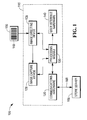
- FIG. 1 is a block diagram illustration of an embodiment of an image scanning system
- FIG. 2 is an illustration of an embodiment of the image directing device
- FIG. 3 is a high level flow diagram of an embodiment of the present invention.
- the image scanning system 100 comprises an image scanner 115, a store server 155 and a bar code 145 printed on a label 150.
- the label 150 is affixed to an item or product (not shown).
- the bar code 145 is printed, applied or manufactured directly onto the item or product.
- the image scanner 115 communicates with the store server 155 over a computer data network 160.
- the network 160 can be a wired network (e.g., an Ethernet network) or wireless network (e.g., an IEEE 802.11G based network) or a combination of both types networks.
- the store server 155 is physically removed from the store where the image scanner 115 is located and communicates with the image scanner 115 over the Internet or a wide area network or a combination of these or different types of networks.
- multiple image scanners 115 are part of the image scanning system 100 and communicate over the data network 160 to the store server 155.
- the image scanner 115 is capable of reading a number of different types of optical codes.
- the optical code is a one dimensional (1D) bar code 145.
- the optical codes read by the image scanner 115 includes a two dimensional (2D) bar code and bar codes that have non-standard sizes.
- the image scanner can read optical codes being displayed on an electronic display such as a personal digital assistant (PDA) or cell phone.
- PDA personal digital assistant
- the image scanner 115 includes an image directing device 125 that receives an optical image and directs the image onto an image capture device 120.
- the image scanner 115 further comprises a processing module 130, user interface hardware 140, and communications hardware 135.
- the processing module 130 comprises at least one processor, memory, stored instructions and control and interface hardware used to control the other devices and modules of the image scanner 115.
- the processing module 130 by executing stored instructions, controls the hardware devices and modules that comprise the image scanner 115.
- the stored instructions cause the processor to: process data such as an image that is captured by the image capture device 120, identify and decode a bar code from the captured image, control the communications hardware 135 to implement protocols used on the data network 160, control the image directing device 125, control the image capture device 120 and implement other software features and functions of the image scanner 115.
- the store server 155 sends the image scanner 115 updates to the stored instructions or to the operating parameters of the image scanner 115.
- updates to the stored instructions are made directly to the image scanner 115 using portable memory storage devices that can communicate directly (e.g., by direct connection or wirelessly) to the image scanner 115. Once received, the updates are stored in the image scanner 15.
- FIG 2 is a detailed illustration of a portion of the image scanner 115.
- an optical image of the bar code 145 enters the image scanner 115 along optical image path 205.
- the image passes through optics 225 that are designed to properly focus the image on the image capture device 120 (once the image has been directed there by the image directing device 125).
- the image then passes to the image directing device 125 and is directed to the image capture device 120 where the optical image is captured by converting it to an electronic image.
- the image directing device 125 can, when instructed to by the processor, cause the image to move or pan across the surface of the image capture device 120.
- the movement or panning of the image is independent of any movement of an object that appears in the image.
- the image directing device 125 comprises a reflecting device 230 that is responsible for directing the incoming optical image to the surface of the image capture device 120.
- the reflective device 230 can move the image focused on the image capture device 120 through a range of locations 220. This is accomplished by tilting the reflective device 230 about an axis 235 through all or part of a range of motion 215.
- An actuator 210 connected to the reflective device 230, is used to move the reflective device 230 through its range of motion 215. In this embodiment, the actuator 210 extends or retracts an arm 245 to move the reflective device 230 through it range of motion 215.
- the processor module 130 through its interface to the actuator 210 controls the speed at which the arm 245 is extended or retracted.
- Adjusting the speed of the actuator 210 controls the angular velocity of the reflecting device 230, which controls the panning speed of the image as it moves across the image capture device 120.
- the processor modules 130 determines that the image is being moving at the correct speed across the image capture device 120 and that the image 205 is properly located on the surface of the image capture device 120, the processor module 130 causes the image capture device 120 to capture an image. Because of the mass of the reflective device 230, the delays in the actuator 210 and the desired angular velocity, the processor module 130 must wait for the reflective device 230 to obtain the desired angular velocity before causing the image capture device 120 to capture the image. While the image directing device 125 can pan an image across the image capture device 120, it can also remain in a fixed position and still direct the image to the image capture device 120.
- the apparent velocity of an object moving past the image scanner 115 relative to the image capture device 120 can be altered. If a bar code 145 is moving in direction 240, the reflected image of the bar code would moved from the bottom 255 to the top 250 of the image capture device 120 (assuming the image directing device 125 remains fixed). If the actuator 210 moves from an extended position to a retracted position, the entire reflected image will be panned from the bottom 255 to the top 250 of the image capture device 120 thus countering some or all of the movement of the reflected bar code in the directed image.
- Reducing the relative motion of the reflected bar code image to the image capture device 120 results in the capture of an image where the blurring of the bar code caused by the movement of the bar code pass the image scanner 115 has been reduced or eliminated. Reducing or eliminating bar code burring increases the ability to read the moving bar code and increases the percentage of good first pass reads for bar codes that are moving past the image scanner.
- the image scanner 115 can be operated in a mode where the image directing device 125 is fixed and does not pan the incoming image. It can also operate in a panning mode where the incoming image is panned across the image capture device 120. In some embodiments, it operates in a hybrid mode where it uses a fix first scan followed by a second panning scan.
- the processor module 130 can also vary the speed of the actuator 210 to better match the speed of the bar code 145 as the bar code 145 moves by the image scanner 115.
- the image scanner 115 takes multiple images of the bar code 145 as it passes by the image scanner 115. In some cases, the retraction or extension speed of the actuator 210 is changed during the same cycle of the actuator 210.
- the processor module 130 may start the actuator 210 moving at one speed and then change the speed all before the actuator reaches its travel limit. During this time, the processor module 130 causes the image capture device 120 to capture multiple images.
- the image scanner will keep statistics regarding the average speed of a bar code presented to the image scanner for reading.
- the image scanner records the image panning speed needed to get a good read of the bar code and averages the speed with other good reads of a bar code.
- the image scanner will determine the level of blurring for the captured bar code image and adjust the panning speed to reduce the blurring and include the adjusted speed in the average. This allows the image scanner to adjust quickly to individual users.
- the present embodiment describes a single axis image directing device 125.
- the image directing device 125 has a second axis of rotation that is used in combination with the first axis to allow panning of the image in two dimensions across the image capture device 120.
- a second actuator is used to move the image reflecting device 230 through a range of motion for the second axis of rotation.
- FIG. 3 there is presented a high level flow diagram for a function of an embodiment of the present invention in which a bar code 145 is read by the image scanner 115.
- a bar code 145 is moved past the image scanner 115.
- the processor in the processor module 130 executes stored instructions that cause the actuator 210 to move, which causes the reflecting device 230 to rotate 310. After a short period of time, the reflecting device 230 reaches a desired angular velocity 310 determined by the processor when it activated the actuator 210.
- the processor causes the image capture device 120 to capture an electronic image of the reflected image containing the bar code 315, when the image is being panned across the image capture device 120.
- the processor processes the captured image to identify and decode the bar code 145.
- the image directing device 125 uses a micro-electro-mechanical system (MEMS) of mirrors to direct the incoming image to the image capture device 120.
- MEMS micro-electro-mechanical system
- the MEMS mirror comprises a number of small mirrors that can be rotated together or individually. By controlling the rotation of the mirrors, a image reflected off the mirrors can be moved or panned across the image capture device 120.
- the image scanner 115 is designed to read additional types of optical codes other than bar codes. These optical codes include text, numbers, symbols and images.
- the image scanner 115 captures an image of an object and identifies the object in the image.
- the object can be a box, car, truck, train car or anything that would move past the image scanner 115 and require identification. Reducing the blurring caused by the motion of the object past the image scanner 115, increases the ability to accurately identify the object.
Landscapes
- Engineering & Computer Science (AREA)
- Physics & Mathematics (AREA)
- Artificial Intelligence (AREA)
- General Health & Medical Sciences (AREA)
- Toxicology (AREA)
- Electromagnetism (AREA)
- Health & Medical Sciences (AREA)
- Computer Vision & Pattern Recognition (AREA)
- General Physics & Mathematics (AREA)
- Theoretical Computer Science (AREA)
- Studio Devices (AREA)
- Image Input (AREA)
- Facsimile Scanning Arrangements (AREA)
Abstract
Description
- An apparatus, method and system described herein relates generally to improvements to a imaging bar code scanner. More particularly, the invention relates to improving the success for reading optical codes on the first pass by the imaging bar code scanner when the optical code has a high passby speed.
- Bar code scanners are used in a wide variety of applications that rely on bar codes to store information. Industries such as retail, airline, self-service, automotive, parcel delivery, pharmaceutical, healthcare and others use optical codes to provide inventory control, customer identification, item tracking, security and many other functions. A bar code is read or scanned by a bar code scanner. The bar code is attached to or printed on an object and contains information about or related to the object. A typical bar code is comprised of a number of bars separated by spaces. Information is encoded on a bar code by varying the width of the bars and spaces. When a bar code is placed within the field of view of a bar code scanner, the scanner will detect, analyze and decode the bars and spaces comprising the bar code to retrieve the information encoded in the bar code. This operation is also called scanning or reading a bar code. The information encoded on a bar code is usually a sequence of numeric or alphanumeric numbers e.g., a Universal Product Code (UPC) or European Article Number (EAN).
- An imaging bar code scanner (also referred to as an image scanner) reads a bar code by capturing a digital image of the bar code and then processing the image to detect and decode the bar code. It is advantageous for the bar code scanner to successfully read all bar codes presented to the scanner on the bar codes first pass by the scanner. This is known as a successful first pass read. Successful first pass reads of bar codes helps to maintain a good workflow at the checkout station and speeds up the overall checkout process. A high first pass read success rate has also been found to reduce stress on the person operating the scanner. This is particularly true if the operator is a customer operating a self-checkout terminal.
- The percentage of successful first pass reads for an imaging scanner is negatively affected as the bar code passby speed increases. As the passby speed of a bar code increases, the image of the bar code captured by the image scanner starts to blur. The blurring reduces the ability of the image scanner to accurately detect and decode the bar code thus reducing the number of successful first pass reads. Because of external factors such as bar code size, bar code fidelity, illumination and bar code orientation to the scanner, the maximum passby speed for a successful first pass read will vary greatly. Since these and other factors are outside the control of the image scanner, it is important to reduce blurring as much as possible using methods that are controlled by the image scanner in order to achieve a high first pass read of a bar code.
- According to a first aspect of the present invention there is provided an optical code image scanner apparatus for scanning an optical code where blurring associated with the movement of the optical code is reduced, the apparatus comprising: an image capture device operable to capture an image comprising the optical code; and an image directing device where the image directing device reduces the apparent motion of the optical code relative to the image capture device by panning a directed image of the optical code across the image capture device as the image capture device captures an image of the optical code
- An image scanning system may include an image capture device operable to capture an image comprising the optical code, and an image directing device where the image directing device reduces the apparent motion of the optical code relative to the image capture device by panning a directed image of the optical code across the image capture device as the image capture device captures an image of the optical code. The optical code may include a bar code.
- According to a second aspect of the present invention there is provided a computer implemented method of scanning an optical code by an optical code image scanner wherein blurring associated with the movement of the optical code past the scanner is reduced, the method comprising: receiving an optical image of the optical code; directing the image of the optical code using an image directing device to an image capture device where the image directing device causes the image to move across the image capture device to reduce the apparent motion of the optical code in the image relative to the image capture device; and using the image capture device, capturing an electronic image of the optical code as the image moves across the image capture device.
- A method of scanning an optical code may include receiving an optical image of the optical code, directing the image of the optical code using an image directing device to an image capture device where the image directing device causes the image to move across the image capture device to reduce the apparent motion of the optical code in the image relative to the image capture device, and using the image capture device, capturing an electronic image of the optical code as the image moves across the image capture device. Directing the image using an image directing device may include causing the image directing device to move the image across the image capture device at a first speed and where capturing an electronic image of the optical code further comprises causing the image capture device to capture the electronic image of the optical code when the image of the optical code has reached the first speed moving across the image capture device. Directing the image using an image directing device may include causing the image directing device to move the image across the image capture device at a second speed and where capturing an electronic image of the optical code further comprises causing the image capture device to capture the electronic image of the optical code when the image of the optical code has reached the second speed moving across the image capture device. The method may further include determining the level of optical code burring in the captured electronic image for each of the first and second speeds and using the results to select the next first speed.
- An image scanning system may include a store server computer, a network connected to the store server computer, and an optical code image scanner connected to the network, including an image capture device to capture an image of the optical code, and an image directing device to direct the image of the optical code to the image capture device, where the image directing device reduces the apparent motion of the optical code relative to the image capture device by panning the directed image of the optical code across the image capture device as the image capture device captures the image. The image directing device may include a movable image reflecting device to pan the directed image across the image capture device. The image reflecting device may be rotated about a single axis. The image reflecting device may be rotatable about two axis. An actuator may be used to move the image reflecting device. The speed at which the actuator moves the image reflecting device may be controllable. A processor may control the image directing device and the image capture device where the processor causes the reflected image to move at a first speed and the causes the image capture device to capture a first image of the optical code when the image is panning across the image capture device and where the processor causes the reflected image to move at a second speed and causes the image capture device to capture a second image of the optical code when the image is panning across the image capture device. The processor may control the image directing device and the image capture device where the processor causes the image capture device to capture an image of the optical code when the image is panning across the image capture device. The image directing device may include a MEMS mirror. The optical code may include a bar code.
- Embodiments of the present invention will now be described with reference to the following drawings, given by way of example, in which
-
FIG. 1 is a block diagram illustration of an embodiment of an image scanning system; -
FIG. 2 is an illustration of an embodiment of the image directing device; and -
FIG. 3 is a high level flow diagram of an embodiment of the present invention. - In the following description, numerous details are set forth to provide an understanding of the claimed invention. However, it will be understood by those skilled in the art that the claimed invention may be practiced without these details and that numerous variations or modifications from the described embodiments are possible.
- Referring now to
FIG. 1 , there is provided a high level illustration, in block form, of an embodiment of animage scanning system 100, which is used to read abar code 145. Theimage scanning system 100 comprises animage scanner 115, astore server 155 and abar code 145 printed on alabel 150. Thelabel 150 is affixed to an item or product (not shown). In some embodiments, thebar code 145 is printed, applied or manufactured directly onto the item or product. Theimage scanner 115 communicates with thestore server 155 over acomputer data network 160. Thenetwork 160 can be a wired network (e.g., an Ethernet network) or wireless network (e.g., an IEEE 802.11G based network) or a combination of both types networks. In some embodiments, thestore server 155 is physically removed from the store where theimage scanner 115 is located and communicates with theimage scanner 115 over the Internet or a wide area network or a combination of these or different types of networks. In some embodiments,multiple image scanners 115 are part of theimage scanning system 100 and communicate over thedata network 160 to thestore server 155. - The
image scanner 115 is capable of reading a number of different types of optical codes. In this embodiment, the optical code is a one dimensional (1D)bar code 145. In other embodiments, the optical codes read by theimage scanner 115 includes a two dimensional (2D) bar code and bar codes that have non-standard sizes. In still other embodiments, the image scanner can read optical codes being displayed on an electronic display such as a personal digital assistant (PDA) or cell phone. - The
image scanner 115 includes animage directing device 125 that receives an optical image and directs the image onto animage capture device 120. Theimage scanner 115 further comprises aprocessing module 130,user interface hardware 140, andcommunications hardware 135. Theprocessing module 130 comprises at least one processor, memory, stored instructions and control and interface hardware used to control the other devices and modules of theimage scanner 115. Theprocessing module 130, by executing stored instructions, controls the hardware devices and modules that comprise theimage scanner 115. In addition, the stored instructions cause the processor to: process data such as an image that is captured by theimage capture device 120, identify and decode a bar code from the captured image, control thecommunications hardware 135 to implement protocols used on thedata network 160, control the image directingdevice 125, control theimage capture device 120 and implement other software features and functions of theimage scanner 115. In some cases, thestore server 155 sends theimage scanner 115 updates to the stored instructions or to the operating parameters of theimage scanner 115. In some embodiments, updates to the stored instructions are made directly to theimage scanner 115 using portable memory storage devices that can communicate directly (e.g., by direct connection or wirelessly) to theimage scanner 115. Once received, the updates are stored in the image scanner 15. -
FIG 2 is a detailed illustration of a portion of theimage scanner 115. In this illustration, an optical image of thebar code 145 enters theimage scanner 115 alongoptical image path 205. The image passes throughoptics 225 that are designed to properly focus the image on the image capture device 120 (once the image has been directed there by the image directing device 125). The image then passes to theimage directing device 125 and is directed to theimage capture device 120 where the optical image is captured by converting it to an electronic image. In addition to simple directing an image to theimage capture device 120, theimage directing device 125 can, when instructed to by the processor, cause the image to move or pan across the surface of theimage capture device 120. The movement or panning of the image is independent of any movement of an object that appears in the image. - The
image directing device 125 comprises a reflectingdevice 230 that is responsible for directing the incoming optical image to the surface of theimage capture device 120. Thereflective device 230 can move the image focused on theimage capture device 120 through a range oflocations 220. This is accomplished by tilting thereflective device 230 about anaxis 235 through all or part of a range ofmotion 215. Anactuator 210, connected to thereflective device 230, is used to move thereflective device 230 through its range ofmotion 215. In this embodiment, theactuator 210 extends or retracts anarm 245 to move thereflective device 230 through it range ofmotion 215. Theprocessor module 130, through its interface to theactuator 210 controls the speed at which thearm 245 is extended or retracted. Adjusting the speed of theactuator 210, controls the angular velocity of the reflectingdevice 230, which controls the panning speed of the image as it moves across theimage capture device 120. When theprocessor modules 130 determines that the image is being moving at the correct speed across theimage capture device 120 and that theimage 205 is properly located on the surface of theimage capture device 120, theprocessor module 130 causes theimage capture device 120 to capture an image. Because of the mass of thereflective device 230, the delays in theactuator 210 and the desired angular velocity, theprocessor module 130 must wait for thereflective device 230 to obtain the desired angular velocity before causing theimage capture device 120 to capture the image. While theimage directing device 125 can pan an image across theimage capture device 120, it can also remain in a fixed position and still direct the image to theimage capture device 120. - By panning an image across the
image capture device 120, the apparent velocity of an object moving past theimage scanner 115 relative to theimage capture device 120 can be altered. If abar code 145 is moving indirection 240, the reflected image of the bar code would moved from the bottom 255 to the top 250 of the image capture device 120 (assuming theimage directing device 125 remains fixed). If theactuator 210 moves from an extended position to a retracted position, the entire reflected image will be panned from the bottom 255 to the top 250 of theimage capture device 120 thus countering some or all of the movement of the reflected bar code in the directed image. Reducing the relative motion of the reflected bar code image to theimage capture device 120 results in the capture of an image where the blurring of the bar code caused by the movement of the bar code pass theimage scanner 115 has been reduced or eliminated. Reducing or eliminating bar code burring increases the ability to read the moving bar code and increases the percentage of good first pass reads for bar codes that are moving past the image scanner. - The
image scanner 115 can be operated in a mode where theimage directing device 125 is fixed and does not pan the incoming image. It can also operate in a panning mode where the incoming image is panned across theimage capture device 120. In some embodiments, it operates in a hybrid mode where it uses a fix first scan followed by a second panning scan. Theprocessor module 130 can also vary the speed of theactuator 210 to better match the speed of thebar code 145 as thebar code 145 moves by theimage scanner 115. Theimage scanner 115 takes multiple images of thebar code 145 as it passes by theimage scanner 115. In some cases, the retraction or extension speed of theactuator 210 is changed during the same cycle of theactuator 210. Theprocessor module 130 may start theactuator 210 moving at one speed and then change the speed all before the actuator reaches its travel limit. During this time, theprocessor module 130 causes theimage capture device 120 to capture multiple images. - In some embodiments, the image scanner will keep statistics regarding the average speed of a bar code presented to the image scanner for reading. The image scanner records the image panning speed needed to get a good read of the bar code and averages the speed with other good reads of a bar code. In some cases, the image scanner will determine the level of blurring for the captured bar code image and adjust the panning speed to reduce the blurring and include the adjusted speed in the average. This allows the image scanner to adjust quickly to individual users.
- The present embodiment describes a single axis
image directing device 125. In other embodiments, theimage directing device 125 has a second axis of rotation that is used in combination with the first axis to allow panning of the image in two dimensions across theimage capture device 120. A second actuator is used to move theimage reflecting device 230 through a range of motion for the second axis of rotation. - Turning now to
FIG. 3 , there is presented a high level flow diagram for a function of an embodiment of the present invention in which abar code 145 is read by theimage scanner 115. Instep 300, abar code 145 is moved past theimage scanner 115. The processor in theprocessor module 130 executes stored instructions that cause theactuator 210 to move, which causes the reflectingdevice 230 to rotate 310. After a short period of time, the reflectingdevice 230 reaches a desiredangular velocity 310 determined by the processor when it activated theactuator 210. The processor causes theimage capture device 120 to capture an electronic image of the reflected image containing thebar code 315, when the image is being panned across theimage capture device 120. The processor processes the captured image to identify and decode thebar code 145. - In other embodiments, the
image directing device 125 uses a micro-electro-mechanical system (MEMS) of mirrors to direct the incoming image to theimage capture device 120. The MEMS mirror comprises a number of small mirrors that can be rotated together or individually. By controlling the rotation of the mirrors, a image reflected off the mirrors can be moved or panned across theimage capture device 120. - In some embodiments, the
image scanner 115 is designed to read additional types of optical codes other than bar codes. These optical codes include text, numbers, symbols and images. - In still other embodiments, the
image scanner 115 captures an image of an object and identifies the object in the image. The object can be a box, car, truck, train car or anything that would move past theimage scanner 115 and require identification. Reducing the blurring caused by the motion of the object past theimage scanner 115, increases the ability to accurately identify the object. - While the invention is disclosed in the context of an image bar code scanning embodiment, it will be recognized that a wide variety of implementations may be employed by a person of ordinary skill in the art consistent with the above discussion and the claims, which follow below.
Claims (10)
- An optical code image scanner apparatus (115) for scanning an optical code (145) where blurring associated with the movement of the optical code (145) is reduced, the apparatus comprising:an image capture device (120) operable to capture an image comprising the optical code (145); andan image directing device (125) where the image directing device (125) reduces the apparent motion of the optical code (145) relative to the image capture device (120) by panning a directed image of the optical code (145) across the image capture device (120) as the image capture device (120) captures an image of the optical code (145).
- The apparatus of claim 1, where the image directing device (125) comprises a movable image reflecting device (230) to pan the directed image across the image capture device (120).
- The apparatus of claim 2, where the image reflecting device (230) is rotated about a single axis (235).
- The apparatus of claim 2, where the image reflecting device (230) is rotatable about two axis.
- The apparatus of claim 2 or 3, where an actuator (210) is used to move the image reflecting device (230).
- The apparatus of claim 5, where the speed at which the actuator moves the image reflecting device is controllable.
- The apparatus of any preceding claim, further comprising a processor (130) that controls the image directing device (125) and the image capture device (120), where the processor (130) causes the image capture device (120) to capture an image of the optical code (145) when the image is panning across the image capture device (120).
- The apparatus of claim 7, wherein the processor (130) causes the reflected image to move at a first speed and then causes the image capture device (120) to capture a first image of the optical code (145) when the image is panning across the image capture device (120) and where the processor (130) causes the reflected image to move at a second speed and then causes the image capture device (120) to capture a second image of the optical code (145) when the image is panning across the image capture device (120).
- The apparatus of any preceding claim, where the image directing device (125) comprises a MEMS mirror.
- A computer implemented method of scanning an optical code by an optical code image scanner wherein blurring associated with the movement of the optical code past the scanner is reduced, the method comprising:receiving an optical image of the optical code;directing the image of the optical code using an image directing device to an image capture device where the image directing device causes the image to move across the image capture device to reduce the apparent motion of the optical code in the image relative to the image capture device; andusing the image capture device, capturing an electronic image of the optical code as the image moves across the image capture device.
Applications Claiming Priority (1)
| Application Number | Priority Date | Filing Date | Title |
|---|---|---|---|
| US12/176,778 US8033468B2 (en) | 2008-07-21 | 2008-07-21 | Apparatus, method and system for an image scanner with differential panning |
Publications (2)
| Publication Number | Publication Date |
|---|---|
| EP2148290A1 true EP2148290A1 (en) | 2010-01-27 |
| EP2148290B1 EP2148290B1 (en) | 2011-08-24 |
Family
ID=40800444
Family Applications (1)
| Application Number | Title | Priority Date | Filing Date |
|---|---|---|---|
| EP09158279A Active EP2148290B1 (en) | 2008-07-21 | 2009-04-20 | An apparatus, method and system for an image scanner with differential panning |
Country Status (5)
| Country | Link |
|---|---|
| US (1) | US8033468B2 (en) |
| EP (1) | EP2148290B1 (en) |
| JP (1) | JP2010028801A (en) |
| AT (1) | ATE521949T1 (en) |
| ES (1) | ES2369125T3 (en) |
Cited By (1)
| Publication number | Priority date | Publication date | Assignee | Title |
|---|---|---|---|---|
| EP2284764A1 (en) * | 2009-07-13 | 2011-02-16 | Honeywell International Inc. | Acquisition system for obtaining sharp barcode images despite motion |
Citations (2)
| Publication number | Priority date | Publication date | Assignee | Title |
|---|---|---|---|---|
| DE19654573A1 (en) * | 1995-12-28 | 1997-07-03 | Samsung Electronics Co Ltd | Image stabilisation circuit with charge-coupled device |
| US20020139857A1 (en) * | 2001-01-30 | 2002-10-03 | Fujitsu Limited | Imaging device |
Family Cites Families (7)
| Publication number | Priority date | Publication date | Assignee | Title |
|---|---|---|---|---|
| JPH06274675A (en) * | 1993-03-23 | 1994-09-30 | Olympus Optical Co Ltd | Bar code symbol reader |
| JPH07199383A (en) * | 1993-12-30 | 1995-08-04 | Keiwa Business:Kk | Method for taking in static image of high-speed moving object and its device for taking in static image |
| US6034379A (en) * | 1996-03-01 | 2000-03-07 | Intermec Ip Corp. | Code reader having replaceable optics assemblies supporting multiple illuminators |
| US6688525B1 (en) * | 1999-09-22 | 2004-02-10 | Eastman Kodak Company | Apparatus and method for reading a coded pattern |
| US6843416B2 (en) * | 2002-01-29 | 2005-01-18 | Symbol Technologies, Inc. | Integrated scanner on a common substrate |
| US7705337B2 (en) * | 2005-11-16 | 2010-04-27 | Microvision, Inc. | System and method for image detection using large area pin diode |
| US20080142598A1 (en) * | 2006-12-14 | 2008-06-19 | Sik Piu Kwan | Method, system, and apparatus for an electronic freeze frame shutter for a high pass-by image scanner |
-
2008
- 2008-07-21 US US12/176,778 patent/US8033468B2/en active Active
-
2009
- 2009-04-20 ES ES09158279T patent/ES2369125T3/en active Active
- 2009-04-20 AT AT09158279T patent/ATE521949T1/en not_active IP Right Cessation
- 2009-04-20 EP EP09158279A patent/EP2148290B1/en active Active
- 2009-05-29 JP JP2009129940A patent/JP2010028801A/en active Pending
Patent Citations (2)
| Publication number | Priority date | Publication date | Assignee | Title |
|---|---|---|---|---|
| DE19654573A1 (en) * | 1995-12-28 | 1997-07-03 | Samsung Electronics Co Ltd | Image stabilisation circuit with charge-coupled device |
| US20020139857A1 (en) * | 2001-01-30 | 2002-10-03 | Fujitsu Limited | Imaging device |
Cited By (1)
| Publication number | Priority date | Publication date | Assignee | Title |
|---|---|---|---|---|
| EP2284764A1 (en) * | 2009-07-13 | 2011-02-16 | Honeywell International Inc. | Acquisition system for obtaining sharp barcode images despite motion |
Also Published As
| Publication number | Publication date |
|---|---|
| JP2010028801A (en) | 2010-02-04 |
| EP2148290B1 (en) | 2011-08-24 |
| ES2369125T3 (en) | 2011-11-25 |
| ATE521949T1 (en) | 2011-09-15 |
| US20100012727A1 (en) | 2010-01-21 |
| US8033468B2 (en) | 2011-10-11 |
Similar Documents
| Publication | Publication Date | Title |
|---|---|---|
| US7571854B2 (en) | Imaging reader and method with internal window reflections directed away from imager | |
| US10013591B2 (en) | Code symbol reading system having adaptive autofocus | |
| US8646694B2 (en) | Indicia reading terminal including frame processing | |
| JP4672725B2 (en) | Trading point workstation for electro-optic reading of one-dimensional marks, including image capture of two-dimensional targets | |
| EP2819062A1 (en) | Mobile device having an improved user interface for reading code symbols | |
| EP2073145B1 (en) | A method, device and system for a laser bar code scanner with imaging assist | |
| US20110233278A1 (en) | Point-of-transaction workstation for electro-optically reading one-dimensional and two-dimensional indicia by image capture | |
| US20120318870A1 (en) | Indicia reading terminal with color frame processing | |
| EP1933253B1 (en) | Method, system, and apparatus for an electronic freeze frame shutter for a high pass-by image scanner | |
| EP2148290B1 (en) | An apparatus, method and system for an image scanner with differential panning | |
| WO2008027170A2 (en) | Imaging reader with variable range | |
| EP1894141B1 (en) | System and method for locating a predetermined pattern within an image | |
| EP2310896B1 (en) | One dimensional barcode reader using two dimensional image sensor | |
| JP2008538150A (en) | In-field upgrade management for data capture systems | |
| US8584951B2 (en) | Apparatus, method and system for extracting pixel data from an image capture device | |
| US20090140051A1 (en) | Method, device and system for off optical axis illumination | |
| US8186596B2 (en) | Apparatus, method and system for selective reading of pixels from an image capture device | |
| US8584952B2 (en) | Apparatus, system and method for extending the depth of field of an optical code scanner |
Legal Events
| Date | Code | Title | Description |
|---|---|---|---|
| PUAI | Public reference made under article 153(3) epc to a published international application that has entered the european phase |
Free format text: ORIGINAL CODE: 0009012 |
|
| AK | Designated contracting states |
Kind code of ref document: A1 Designated state(s): AT BE BG CH CY CZ DE DK EE ES FI FR GB GR HR HU IE IS IT LI LT LU LV MC MK MT NL NO PL PT RO SE SI SK TR |
|
| AX | Request for extension of the european patent |
Extension state: AL BA RS |
|
| RAP1 | Party data changed (applicant data changed or rights of an application transferred) |
Owner name: NCR CORPORATION |
|
| 17P | Request for examination filed |
Effective date: 20100727 |
|
| GRAP | Despatch of communication of intention to grant a patent |
Free format text: ORIGINAL CODE: EPIDOSNIGR1 |
|
| RIC1 | Information provided on ipc code assigned before grant |
Ipc: G06K 7/10 20060101AFI20110414BHEP |
|
| GRAS | Grant fee paid |
Free format text: ORIGINAL CODE: EPIDOSNIGR3 |
|
| GRAA | (expected) grant |
Free format text: ORIGINAL CODE: 0009210 |
|
| AK | Designated contracting states |
Kind code of ref document: B1 Designated state(s): AT BE BG CH CY CZ DE DK EE ES FI FR GB GR HR HU IE IS IT LI LT LU LV MC MK MT NL NO PL PT RO SE SI SK TR |
|
| REG | Reference to a national code |
Ref country code: GB Ref legal event code: FG4D Ref country code: DE Ref legal event code: R084 Ref document number: 602009002236 Country of ref document: DE |
|
| REG | Reference to a national code |
Ref country code: CH Ref legal event code: EP |
|
| REG | Reference to a national code |
Ref country code: IE Ref legal event code: FG4D |
|
| REG | Reference to a national code |
Ref country code: GB Ref legal event code: 746 Effective date: 20110905 |
|
| REG | Reference to a national code |
Ref country code: DE Ref legal event code: R096 Ref document number: 602009002236 Country of ref document: DE Effective date: 20111020 |
|
| REG | Reference to a national code |
Ref country code: DE Ref legal event code: R084 Ref document number: 602009002236 Country of ref document: DE Effective date: 20110824 |
|
| REG | Reference to a national code |
Ref country code: ES Ref legal event code: FG2A Ref document number: 2369125 Country of ref document: ES Kind code of ref document: T3 Effective date: 20111125 |
|
| REG | Reference to a national code |
Ref country code: NL Ref legal event code: VDEP Effective date: 20110824 |
|
| LTIE | Lt: invalidation of european patent or patent extension |
Effective date: 20110824 |
|
| PG25 | Lapsed in a contracting state [announced via postgrant information from national office to epo] |
Ref country code: SE Free format text: LAPSE BECAUSE OF FAILURE TO SUBMIT A TRANSLATION OF THE DESCRIPTION OR TO PAY THE FEE WITHIN THE PRESCRIBED TIME-LIMIT Effective date: 20110824 Ref country code: FI Free format text: LAPSE BECAUSE OF FAILURE TO SUBMIT A TRANSLATION OF THE DESCRIPTION OR TO PAY THE FEE WITHIN THE PRESCRIBED TIME-LIMIT Effective date: 20110824 Ref country code: LT Free format text: LAPSE BECAUSE OF FAILURE TO SUBMIT A TRANSLATION OF THE DESCRIPTION OR TO PAY THE FEE WITHIN THE PRESCRIBED TIME-LIMIT Effective date: 20110824 Ref country code: NL Free format text: LAPSE BECAUSE OF FAILURE TO SUBMIT A TRANSLATION OF THE DESCRIPTION OR TO PAY THE FEE WITHIN THE PRESCRIBED TIME-LIMIT Effective date: 20110824 Ref country code: PT Free format text: LAPSE BECAUSE OF FAILURE TO SUBMIT A TRANSLATION OF THE DESCRIPTION OR TO PAY THE FEE WITHIN THE PRESCRIBED TIME-LIMIT Effective date: 20111226 Ref country code: HR Free format text: LAPSE BECAUSE OF FAILURE TO SUBMIT A TRANSLATION OF THE DESCRIPTION OR TO PAY THE FEE WITHIN THE PRESCRIBED TIME-LIMIT Effective date: 20110824 Ref country code: NO Free format text: LAPSE BECAUSE OF FAILURE TO SUBMIT A TRANSLATION OF THE DESCRIPTION OR TO PAY THE FEE WITHIN THE PRESCRIBED TIME-LIMIT Effective date: 20111124 Ref country code: IS Free format text: LAPSE BECAUSE OF FAILURE TO SUBMIT A TRANSLATION OF THE DESCRIPTION OR TO PAY THE FEE WITHIN THE PRESCRIBED TIME-LIMIT Effective date: 20111224 |
|
| REG | Reference to a national code |
Ref country code: AT Ref legal event code: MK05 Ref document number: 521949 Country of ref document: AT Kind code of ref document: T Effective date: 20110824 |
|
| PG25 | Lapsed in a contracting state [announced via postgrant information from national office to epo] |
Ref country code: PL Free format text: LAPSE BECAUSE OF FAILURE TO SUBMIT A TRANSLATION OF THE DESCRIPTION OR TO PAY THE FEE WITHIN THE PRESCRIBED TIME-LIMIT Effective date: 20110824 Ref country code: AT Free format text: LAPSE BECAUSE OF FAILURE TO SUBMIT A TRANSLATION OF THE DESCRIPTION OR TO PAY THE FEE WITHIN THE PRESCRIBED TIME-LIMIT Effective date: 20110824 Ref country code: LV Free format text: LAPSE BECAUSE OF FAILURE TO SUBMIT A TRANSLATION OF THE DESCRIPTION OR TO PAY THE FEE WITHIN THE PRESCRIBED TIME-LIMIT Effective date: 20110824 Ref country code: SI Free format text: LAPSE BECAUSE OF FAILURE TO SUBMIT A TRANSLATION OF THE DESCRIPTION OR TO PAY THE FEE WITHIN THE PRESCRIBED TIME-LIMIT Effective date: 20110824 Ref country code: CY Free format text: LAPSE BECAUSE OF FAILURE TO SUBMIT A TRANSLATION OF THE DESCRIPTION OR TO PAY THE FEE WITHIN THE PRESCRIBED TIME-LIMIT Effective date: 20110824 Ref country code: GR Free format text: LAPSE BECAUSE OF FAILURE TO SUBMIT A TRANSLATION OF THE DESCRIPTION OR TO PAY THE FEE WITHIN THE PRESCRIBED TIME-LIMIT Effective date: 20111125 |
|
| PG25 | Lapsed in a contracting state [announced via postgrant information from national office to epo] |
Ref country code: BE Free format text: LAPSE BECAUSE OF FAILURE TO SUBMIT A TRANSLATION OF THE DESCRIPTION OR TO PAY THE FEE WITHIN THE PRESCRIBED TIME-LIMIT Effective date: 20110824 |
|
| PG25 | Lapsed in a contracting state [announced via postgrant information from national office to epo] |
Ref country code: SK Free format text: LAPSE BECAUSE OF FAILURE TO SUBMIT A TRANSLATION OF THE DESCRIPTION OR TO PAY THE FEE WITHIN THE PRESCRIBED TIME-LIMIT Effective date: 20110824 Ref country code: CZ Free format text: LAPSE BECAUSE OF FAILURE TO SUBMIT A TRANSLATION OF THE DESCRIPTION OR TO PAY THE FEE WITHIN THE PRESCRIBED TIME-LIMIT Effective date: 20110824 |
|
| REG | Reference to a national code |
Ref country code: ES Ref legal event code: GC2A Effective date: 20120427 |
|
| PG25 | Lapsed in a contracting state [announced via postgrant information from national office to epo] |
Ref country code: EE Free format text: LAPSE BECAUSE OF FAILURE TO SUBMIT A TRANSLATION OF THE DESCRIPTION OR TO PAY THE FEE WITHIN THE PRESCRIBED TIME-LIMIT Effective date: 20110824 Ref country code: RO Free format text: LAPSE BECAUSE OF FAILURE TO SUBMIT A TRANSLATION OF THE DESCRIPTION OR TO PAY THE FEE WITHIN THE PRESCRIBED TIME-LIMIT Effective date: 20110824 |
|
| PG25 | Lapsed in a contracting state [announced via postgrant information from national office to epo] |
Ref country code: DK Free format text: LAPSE BECAUSE OF FAILURE TO SUBMIT A TRANSLATION OF THE DESCRIPTION OR TO PAY THE FEE WITHIN THE PRESCRIBED TIME-LIMIT Effective date: 20110824 |
|
| PLBE | No opposition filed within time limit |
Free format text: ORIGINAL CODE: 0009261 |
|
| STAA | Information on the status of an ep patent application or granted ep patent |
Free format text: STATUS: NO OPPOSITION FILED WITHIN TIME LIMIT |
|
| 26N | No opposition filed |
Effective date: 20120525 |
|
| REG | Reference to a national code |
Ref country code: DE Ref legal event code: R097 Ref document number: 602009002236 Country of ref document: DE Effective date: 20120525 |
|
| PG25 | Lapsed in a contracting state [announced via postgrant information from national office to epo] |
Ref country code: MC Free format text: LAPSE BECAUSE OF NON-PAYMENT OF DUE FEES Effective date: 20120430 |
|
| REG | Reference to a national code |
Ref country code: IE Ref legal event code: MM4A |
|
| PG25 | Lapsed in a contracting state [announced via postgrant information from national office to epo] |
Ref country code: IE Free format text: LAPSE BECAUSE OF NON-PAYMENT OF DUE FEES Effective date: 20120420 |
|
| PG25 | Lapsed in a contracting state [announced via postgrant information from national office to epo] |
Ref country code: MK Free format text: LAPSE BECAUSE OF FAILURE TO SUBMIT A TRANSLATION OF THE DESCRIPTION OR TO PAY THE FEE WITHIN THE PRESCRIBED TIME-LIMIT Effective date: 20110824 |
|
| PG25 | Lapsed in a contracting state [announced via postgrant information from national office to epo] |
Ref country code: BG Free format text: LAPSE BECAUSE OF FAILURE TO SUBMIT A TRANSLATION OF THE DESCRIPTION OR TO PAY THE FEE WITHIN THE PRESCRIBED TIME-LIMIT Effective date: 20111124 |
|
| PG25 | Lapsed in a contracting state [announced via postgrant information from national office to epo] |
Ref country code: MT Free format text: LAPSE BECAUSE OF FAILURE TO SUBMIT A TRANSLATION OF THE DESCRIPTION OR TO PAY THE FEE WITHIN THE PRESCRIBED TIME-LIMIT Effective date: 20110824 |
|
| REG | Reference to a national code |
Ref country code: CH Ref legal event code: PL |
|
| PG25 | Lapsed in a contracting state [announced via postgrant information from national office to epo] |
Ref country code: LI Free format text: LAPSE BECAUSE OF NON-PAYMENT OF DUE FEES Effective date: 20130430 Ref country code: CH Free format text: LAPSE BECAUSE OF NON-PAYMENT OF DUE FEES Effective date: 20130430 |
|
| PG25 | Lapsed in a contracting state [announced via postgrant information from national office to epo] |
Ref country code: TR Free format text: LAPSE BECAUSE OF FAILURE TO SUBMIT A TRANSLATION OF THE DESCRIPTION OR TO PAY THE FEE WITHIN THE PRESCRIBED TIME-LIMIT Effective date: 20110824 |
|
| PG25 | Lapsed in a contracting state [announced via postgrant information from national office to epo] |
Ref country code: LU Free format text: LAPSE BECAUSE OF NON-PAYMENT OF DUE FEES Effective date: 20120420 |
|
| PG25 | Lapsed in a contracting state [announced via postgrant information from national office to epo] |
Ref country code: HU Free format text: LAPSE BECAUSE OF FAILURE TO SUBMIT A TRANSLATION OF THE DESCRIPTION OR TO PAY THE FEE WITHIN THE PRESCRIBED TIME-LIMIT Effective date: 20090420 |
|
| REG | Reference to a national code |
Ref country code: FR Ref legal event code: PLFP Year of fee payment: 8 |
|
| REG | Reference to a national code |
Ref country code: FR Ref legal event code: PLFP Year of fee payment: 9 |
|
| REG | Reference to a national code |
Ref country code: FR Ref legal event code: PLFP Year of fee payment: 10 |
|
| REG | Reference to a national code |
Ref country code: DE Ref legal event code: R081 Ref document number: 602009002236 Country of ref document: DE Owner name: NCR VOYIX CORP., ATLANTA, US Free format text: FORMER OWNER: NCR CORP., DULUTH, GA., US Ref country code: DE Ref legal event code: R082 Ref document number: 602009002236 Country of ref document: DE Representative=s name: V. BEZOLD & PARTNER PATENTANWAELTE - PARTG MBB, DE Ref country code: DE Ref legal event code: R081 Ref document number: 602009002236 Country of ref document: DE Owner name: NCR CORPORATION, ATLANTA, US Free format text: FORMER OWNER: NCR CORP., DULUTH, GA., US |
|
| P01 | Opt-out of the competence of the unified patent court (upc) registered |
Effective date: 20230505 |
|
| REG | Reference to a national code |
Ref country code: DE Ref legal event code: R081 Ref document number: 602009002236 Country of ref document: DE Owner name: NCR VOYIX CORP., ATLANTA, US Free format text: FORMER OWNER: NCR CORPORATION, ATLANTA, GA, US |
|
| REG | Reference to a national code |
Ref country code: ES Ref legal event code: PC2A Owner name: NCR VOYIX CORPORATION Effective date: 20241021 |
|
| PGFP | Annual fee paid to national office [announced via postgrant information from national office to epo] |
Ref country code: DE Payment date: 20250429 Year of fee payment: 17 |
|
| PGFP | Annual fee paid to national office [announced via postgrant information from national office to epo] |
Ref country code: GB Payment date: 20250428 Year of fee payment: 17 Ref country code: ES Payment date: 20250505 Year of fee payment: 17 |
|
| PGFP | Annual fee paid to national office [announced via postgrant information from national office to epo] |
Ref country code: IT Payment date: 20250422 Year of fee payment: 17 |
|
| PGFP | Annual fee paid to national office [announced via postgrant information from national office to epo] |
Ref country code: FR Payment date: 20250425 Year of fee payment: 17 |