EP2148250A2 - Image forming apparatus and print instruction apparatus - Google Patents
Image forming apparatus and print instruction apparatus Download PDFInfo
- Publication number
- EP2148250A2 EP2148250A2 EP09165427A EP09165427A EP2148250A2 EP 2148250 A2 EP2148250 A2 EP 2148250A2 EP 09165427 A EP09165427 A EP 09165427A EP 09165427 A EP09165427 A EP 09165427A EP 2148250 A2 EP2148250 A2 EP 2148250A2
- Authority
- EP
- European Patent Office
- Prior art keywords
- sheet
- image forming
- information
- section
- reverse side
- Prior art date
- Legal status (The legal status is an assumption and is not a legal conclusion. Google has not performed a legal analysis and makes no representation as to the accuracy of the status listed.)
- Withdrawn
Links
- 238000012545 processing Methods 0.000 claims abstract description 66
- 230000015572 biosynthetic process Effects 0.000 claims description 11
- 238000004891 communication Methods 0.000 description 31
- 230000006870 function Effects 0.000 description 26
- 238000000034 method Methods 0.000 description 15
- 238000010586 diagram Methods 0.000 description 8
- 238000012546 transfer Methods 0.000 description 8
- 230000000994 depressogenic effect Effects 0.000 description 6
- 238000000926 separation method Methods 0.000 description 6
- 239000011521 glass Substances 0.000 description 2
- 238000003780 insertion Methods 0.000 description 2
- 230000037431 insertion Effects 0.000 description 2
- 230000002093 peripheral effect Effects 0.000 description 2
- 239000004065 semiconductor Substances 0.000 description 2
- 101100108208 Arabidopsis thaliana ADF12 gene Proteins 0.000 description 1
- 238000006243 chemical reaction Methods 0.000 description 1
- 239000003086 colorant Substances 0.000 description 1
- 230000000881 depressing effect Effects 0.000 description 1
- 239000004973 liquid crystal related substance Substances 0.000 description 1
- 108091008695 photoreceptors Proteins 0.000 description 1
- 238000004080 punching Methods 0.000 description 1
Images







Classifications
-
- G—PHYSICS
- G03—PHOTOGRAPHY; CINEMATOGRAPHY; ANALOGOUS TECHNIQUES USING WAVES OTHER THAN OPTICAL WAVES; ELECTROGRAPHY; HOLOGRAPHY
- G03G—ELECTROGRAPHY; ELECTROPHOTOGRAPHY; MAGNETOGRAPHY
- G03G15/00—Apparatus for electrographic processes using a charge pattern
- G03G15/22—Apparatus for electrographic processes using a charge pattern involving the combination of more than one step according to groups G03G13/02 - G03G13/20
- G03G15/23—Apparatus for electrographic processes using a charge pattern involving the combination of more than one step according to groups G03G13/02 - G03G13/20 specially adapted for copying both sides of an original or for copying on both sides of a recording or image-receiving material
- G03G15/231—Arrangements for copying on both sides of a recording or image-receiving material
- G03G15/232—Arrangements for copying on both sides of a recording or image-receiving material using a single reusable electrographic recording member
- G03G15/234—Arrangements for copying on both sides of a recording or image-receiving material using a single reusable electrographic recording member by inverting and refeeding the image receiving material with an image on one face to the recording member to transfer a second image on its second face, e.g. by using a duplex tray; Details of duplex trays or inverters
- G03G15/235—Arrangements for copying on both sides of a recording or image-receiving material using a single reusable electrographic recording member by inverting and refeeding the image receiving material with an image on one face to the recording member to transfer a second image on its second face, e.g. by using a duplex tray; Details of duplex trays or inverters the image receiving member being preconditioned before transferring the second image, e.g. decurled, or the second image being formed with different operating parameters, e.g. a different fixing temperature
-
- G—PHYSICS
- G03—PHOTOGRAPHY; CINEMATOGRAPHY; ANALOGOUS TECHNIQUES USING WAVES OTHER THAN OPTICAL WAVES; ELECTROGRAPHY; HOLOGRAPHY
- G03G—ELECTROGRAPHY; ELECTROPHOTOGRAPHY; MAGNETOGRAPHY
- G03G15/00—Apparatus for electrographic processes using a charge pattern
- G03G15/65—Apparatus which relate to the handling of copy material
- G03G15/6588—Apparatus which relate to the handling of copy material characterised by the copy material, e.g. postcards, large copies, multi-layered materials, coloured sheet material
- G03G15/6594—Apparatus which relate to the handling of copy material characterised by the copy material, e.g. postcards, large copies, multi-layered materials, coloured sheet material characterised by the format or the thickness, e.g. endless forms
-
- G—PHYSICS
- G03—PHOTOGRAPHY; CINEMATOGRAPHY; ANALOGOUS TECHNIQUES USING WAVES OTHER THAN OPTICAL WAVES; ELECTROGRAPHY; HOLOGRAPHY
- G03G—ELECTROGRAPHY; ELECTROPHOTOGRAPHY; MAGNETOGRAPHY
- G03G2215/00—Apparatus for electrophotographic processes
- G03G2215/00362—Apparatus for electrophotographic processes relating to the copy medium handling
- G03G2215/00443—Copy medium
- G03G2215/00451—Paper
-
- G—PHYSICS
- G03—PHOTOGRAPHY; CINEMATOGRAPHY; ANALOGOUS TECHNIQUES USING WAVES OTHER THAN OPTICAL WAVES; ELECTROGRAPHY; HOLOGRAPHY
- G03G—ELECTROGRAPHY; ELECTROPHOTOGRAPHY; MAGNETOGRAPHY
- G03G2215/00—Apparatus for electrophotographic processes
- G03G2215/00362—Apparatus for electrophotographic processes relating to the copy medium handling
- G03G2215/00535—Stable handling of copy medium
- G03G2215/00717—Detection of physical properties
Definitions
- the present invention relates to an image forming apparatus and a print instruction apparatus.
- An image forming apparatus such as Multifunction Peripheral (MFP) previously receives an input of sheet information (such as paper quality, color, basis weight of a sheet) of a print sheet to be image-formed so as to switch a control of image forming processing based on the sheet information, and thereby a jam is reduced and image quality is improved.
- sheet information such as paper quality, color, basis weight of a sheet
- an image forming apparatus can accept only one-side sheet information.
- a print sheet for example, a print sheet where types of sheet processing of the obverse side and reverse side are different from each other
- an image forming apparatus can accept only one-side sheet information.
- the user firstly inputs the sheet information of the obverse side into the image forming apparatus. Secondly, the user allows the image forming apparatus to perform single-side printing on the obverse side of the print sheet. Next, the user inputs the sheet information of the reverse side into the image forming apparatus. Then, the user allows the image forming apparatus to perform single-side printing on the reverse side of the print sheet.
- the prevent invention has been achieved in view of the abovementioned problems, and the object of the present invention is to improve user's working efficiency when image forming processing is performed on both sides of a sheet whose obverse side and reverse side have different attributes from each other.
- an image forming apparatus to perform image forming processing based on a print job, which image forming apparatus including: a storage section to store obverse side information indicating an attribute specific to an obverse side of a sheet and reverse side information indicating an attribute specific to a reverse side of the sheet; and a control section to perform image forming processing on the obverse side of the sheet in an image forming condition according to the obverse side information stored in the storage section, and to perform image forming processing on the reverse side of the sheet in an image forming condition according to the reverse side information stored in the storage section, when image forming processing is performed on both sides of the sheet based on the print job.
- the storage section further stores common information indicating an attribute of the sheet itself, which attribute is common between the obverse side and the reverse side of the sheet, and the control section performs image forming processing on the obverse side of the sheet in an image forming condition according to the obverse side information and the common information which are stored in the storage section, and performs image forming processing on the reverse side of the sheet in an image forming condition according to the reverse side information and the common information which are stored in the storage section.
- the image forming apparatus further includes: an operation section to receive the obverse side information, the reverse side information and the common information respectively, and wherein the control section allows the storage section to store the obverse information, the reverse information and the common information which are received by the operation section.
- each item regarding the obverse side information and the reverse side information which are received by the operation section includes at least one of items regarding a type of sheet processing and a sheet color
- an item regarding the common information received by the operation section includes at least one of items regarding a basis weight of the sheet and presence/absence of a punch hole.
- the image forming apparatus includes: a feeding section to feed the stored sheet, and wherein when image forming processing is performed on both sides of the sheet according to the print job, the control section specifies the sheet specified in the print job based on the obverse side information, the reverse side information, and the common information which are stored in the storage section, to supply the specified sheet to the feeding section.
- the storage section further stores common information indicating an attribute of the sheet itself, which is common between the obverse side and the reverse side of the sheet, and the control section generates, as the print job, a print job further including the common information.
- Fig. 1 shows a system configuration of an image forming system 100.
- the image forming system 100 is composed of an image forming apparatus 10 and a client terminal 20 which are data communicatably connected to each other through a communication network N such as a LAN.
- a communication network N such as a LAN.
- the image forming apparatus 10 is so-called Multifunction Peripheral (MFP) including a copying function, image reading function and printing function, and forms an image on a sheet based on a print job (print instruction) transmitted from the client terminal 20, image data read by an image reading section such as a scanner provided in the image forming apparatus 10, and so on.
- MFP Multifunction Peripheral
- the client terminal 20 is so-called personal computer, includes a function to transmit the print job to the image forming apparatus 10, and acts as a print instruction apparatus.
- the client terminal 20 is provided with a printer driver program (hereinafter referred to as simply printer driver in some cases) installed therein, and uses a function of the printer driver to create the print job including print condition data (print job information) to be applied in image formation, image data, and so on, to transmit the created print job to the image forming apparatus 10.
- a printer driver program hereinafter referred to as simply printer driver in some cases
- Fig. 2 shows a configuration of the image forming apparatus 10.
- the image forming apparatus 10 is configured to include: a control section 11; an Auto Document Feeder (ADF) 12; an image reading section 13; an operation section 14; a display section 15; an image outputting section 16; an image forming section 17; a first feeding section 18a; a second feeding section 18b; a third feeding section 18c; and a fourth feeding section 18d.
- ADF Auto Document Feeder
- the ADF 12 is an automatic document feeding apparatus, and automatically conveys a single sheet or a plurality of sheets to the image reading section 13.
- the image reading section 13 is a function section to optically read the image on the document placed on a document rest to create the image data. Specifically, the image reading section 13 optically scans the document conveyed by the ADF 12 through a contact glass, or optically scans the document placed on the platen glass, to read the image recorded on the document image by photoelectric conversion with a Charge-Coupled Device (CCD) image sensor to create the image data of the read image to output the created image data to the image forming section 17.
- CCD Charge-Coupled Device
- the image forming section 17 is a function section to form an image, and includes not-shown photoreceptor, transfer belt, fixer, various conveying belts and the like.
- the image forming section 17 forms the image on the print sheet based on the image data read by the image reading section 13 or the print job transmitted through the communication I/F section to output the image to the image outputting section 16.
- a known image process such as an electrophotography system and electrostatic recording system may be used.
- the image forming section 17 is capable of forming the image on both sides, namely the obverse side and reverse side, of the print sheet.
- the control section 11 controls each of the function sections, and includes a Central Processing Unit (CPU), Random Access Memory (RAM), storage section and the like. The details will be described later.
- CPU Central Processing Unit
- RAM Random Access Memory
- the first feeding section 18a, the second feeding section 18b, the third feeding section 18c and the fourth feeding section 18d store the sheet (print sheet) and send forth the stored print to the image forming section 17 respectively.
- the first-fourth feeding sections 18a-18d are referred to generically as a feeding section 18.
- the operation section 14 and the display section 15 are integrally configured with operation input keys, touch panel and the like.
- the operation section 14 outputs operation signals including a depression signal corresponding to a depressed key, and a position signal corresponding to a pushed position on the touch panel, to the control section 11.
- the display section 15 displays a feeding section information setting screen (see Figs. 7 and 8 ), a print job information inputting screen (see Fig. 9 ), and so on.
- the image outputting section 16 is a function section to perform finishing processing such as punching, stapling, and bookbinding on the sheet conveyed from the image forming section 17 according to the instruction from the control section 11 to output the processed sheet.
- Fig. 3 is a block diagram of the control section 11 and each of the function sections.
- the control section 11 is configured to include a CPU 111, RAM 112, storage section 113 and communication I/F section 114 which are communicably connected to one another through a bus.
- each of the function sections constructing the control section 11 is communicably connected to the ADF 12, image reading section 13, operation section 14, display section 15, image outputting section 16, image forming section 17 and feeding section 18 through the bus.
- the communication I/F section 114 is communicably connected to the communication network N such as a LAN.
- the CPU 111 reads various processing programs stored in the storage section 113 to expand the programs in a work area formed in the RAM 112 to perform various processing in cooperation with the programs.
- the CPU 111 integrally manages/controls the image forming apparatus 10 by controlling an operation of each of the function sections, controlling data input/output among the function sections, and so on.
- the function sections are specifically the ADF12, image reading section 13, operation section 14, display section 15, image outputting section 16, image forming section 17 and feeding section 18.
- the CPU 111 analyzes the print job when receiving the print job to output instructions for image forming processing to each of the function sections.
- the RAM 112 is a section to temporarily store various pieces of data read by the image reading section 13 or input from the communication I/F section 114.
- the stored data is processed by the CPU 111, and transferred to the storage section 113 or the image forming section 17 as necessary.
- the RAM 112 stores the print job.
- the print job is, for example, composed of print job information indicating a print condition and image data indicating the image to be printed.
- the image data is composed of four colors of cyan (C), yellow (Y), magenta (M) and black (B), for example.
- the CPU 111 receives the print job from other communication equipments through the communication I/F section 114.
- the image data may be information read by the image reading section 13, and the print job information may be information set by an input signal from the operation section 14.
- the communication I/F section 114 receives the print job, the CPU 111 allows the RAM 112 to store the print job.
- the print job may include, in place of the image data, the image to be printed in a file format such as Portable Document Format (PDF) and XML Paper Specification (XPS), or in Page Description Language (PDL) format such as PostScript (registered trademark) (PS) and Printer Control Language (PCL).
- PDF Portable Document Format
- XPS XML Paper Specification
- PDL Page Description Language
- PS PostScript
- PCL Printer Control Language
- Fig. 4 shows a data configuration of the print job information.
- the print job information d1 includes information such as "job ID”, “user name”, “job name”, “the number of sets”, “printing method”, “sheet type (obverse side)”, “sheet type (reverse side)", and “basis weight”.
- the "printing method” is information indicating which of duplex printing or single-side printing is to be performed, and has a value of one of "both sides” and "single side”. The “both sides” corresponds to duplex printing, and the "single side” corresponds to single-side printing.
- the "sheet type (obverse side)” is information of a type of sheet processing on the obverse side of the print sheet
- the “sheet type (reverse side)” is information of a type of sheet processing on the reverse side of the print sheet.
- Each of pieces of the information includes values such as "plain”, “coated” and “rough”.
- the "plain” corresponds to a plain sheet
- the "coated” corresponds to a coated sheet
- the "rough” corresponds to a rough sheet.
- the basis weight is print sheet weight per one square meter. While the "sheet type (obverse side)" is an attribute specific to the obverse side and the “sheet type (reverse side)” is an attribute specific to the reverse side, the "basis weight” is an attribute of the sheet itself. The attribute of sheet itself is common attribute between the obverse side and the reverse side.
- the storage section 113 is composed of a Hard Disk Drive (HDD), a semiconductor nonvolatile memory, and so on.
- the storage section 113 stores a program for allowing the CPU 111 to control each of the function sections and information regarding processing function of the image forming apparatus 10. These program and information are read as necessary by the CPU 111 to be executed/processed on the RAM 112.
- the storage section 113 stores feeding section information d2 (see Fig. 5 ), print control condition information d3 (see Fig. 6 ), and the like.
- the feeding section information d2 is sheet information indicating the attribute of the print sheet stored in the feeding section 18.
- the print control condition information d3 is information indicating a processing parameter (image forming condition) of print control (image forming processing) according to the attribute (sheet type and the like) of the print sheet.
- the feeding section information d2 includes: a first feeding section information d21 which is sheet information of the print sheet stored in the first feeding section 18a; a second feeding section information d22 which is sheet information of the print sheet stored in the second feeding section 18b; a third feeding section information d23 which is sheet information of the print sheet stored in the third feeding section 18c; and a fourth feeding section information d24 which is sheet information of the print sheet stored in the fourth feeding section 18d.
- Each of pieces of the first-fourth feeding section information d21-d24 includes sheet information such as "sheet size”, “sheet type (obverse side)”, “sheet type (reverse side)", “basis weight”, “colored sheet”, “punch hole”, and so on.
- the sheet information includes: obverse side information indicating the attribute specific to the obverse side of the sheet; reverse side information indicating the attribute specific to the reverse side of the sheet; and common information indicating the attribute of the sheet itself.
- obverse side information “sheet type (obverse side)” may be cited, as an example of the reverse side information, “sheet type (reverse side)” may be cited, and as examples of the common information, “sheet size”, “"basis weight”, “colored sheet”, “punch hole” and the like may be cited.
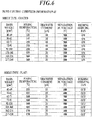
- Fig. 6 shows a part of the data configuration of the print control condition information d3.
- the print control condition information d3 shown in Fig. 6 represents information such as "fixing temperature”, “transfer current”, “separation DC voltage” and “feeding assisting fan” per "basis weight” of the common information, depending on “sheet type (obverse side)” which is one of the pieces of the obverse side information, and “sheet type (reverse side)” which is one of the pieces of the reverse side information.
- the CPU 111 transmits the instruction regarding the print control to each of the function sections based on these values.
- the CPU 111 transmits the instruction to form the image in the condition that the fixing temperature is 150 C °, the transfer current is 10 ⁇ A, and the separation DC voltage is 500V to the image forming section 17, and transmits the instruction to feed the print sheet while the feeding assisting fan is in on-state to the feeding section 18.
- the CPU 111 transmits the instruction to form the image in the condition that the fixing temperature is 165 C °, the transfer current is 25 ⁇ A, and the separation DC voltage is 400V to the image forming section 17, and transmits the instruction to feed the print sheet while the feeding assisting fan is in off-state to the feeding section 18.
- each of the function sections executes processing regarding the print control according to the instruction transmitted from the CPU 111.
- the communication I/F section 114 is composed of a LAN interface, modem, and so on, and is a function section to perform data communication with external equipment such as a server, client, other apparatuses, and the like through the communication network N and the like.
- the communication I/F section 114 receives feeding section information setting data, feeding section information acquisition request, print job and the like from the other communication equipment.
- the CPU 111 updates the value of the feeding section information d2 based on the feeding section information setting data when receiving the feeding section information setting data through the communication I/F section 114. Specifically, the CPU 111 updates items such as "sheet type (obverse side)", “sheet type (reverse side)", “basis weight”, "colored sheet” and “punch hole” of the first feeding section information d21 stored in the RAM 112 and the storage section 113 based on the feeding section information setting data when receiving the feeding section information setting data regarding the first feeding section 18a.
- the CPU 111 allows the RAM 112 to temporality store the print job when receiving the print job through the communication I/F section 114. Then, the CPU 111 performs on the RAM 112 converting processing to convert the image data included in the print job into print image data, which is capable of being image-formed on the print sheet in the image forming section 17.
- the storage section 113 stores various programs for converting the image data into the print image data, and the CPU 111 reads necessary programs.
- the CPU 111 updates the value of the feeding section information d2 based on an input signal from the operation section 14. Specifically, the CPU 111 updates the items such as "sheet type (obverse side)", “sheet type (reverse side)", “basis weight”, "colored sheet” and “punch hole” of the first feeding section information d21 stored in the RAM 112 and the storage section 113 based on the input signal when receiving an input signal indicating updating of the feed section information d2 regarding the first feeding section 18a.
- the CPU 111 receives the image data from the image reading section 13 to create (set) the print job information based on the input signal from the operation section 14, and then allows the RAM 112 to temporarily store the image data and the print job information as the print job. After that, the CPU 111 executes on the RAM 112 converting processing to convert the image data included in the print job into the print image data, which is capable of being image-formed on the print sheet in the image forming section 17.
- the CPU 111 allows the display section 15 to display feeding section information setting screen 151 (see Figs. 7 and 8 ) and print job information inputting screen 152 (see Fig. 9 ) based on the input signal from the operation section 14.
- the CPU 111 transmits the feeding section information d2 stored in the RAM 112 to a source of the feeding section information acquisition request when receiving the feeding section information acquisition request through the communication I/F section 114.
- Figs. 7 and 8 show examples of the feeding section information setting screen 151 to be displayed on the display section 15. Figs. 7 and 8 show same screens.
- the feeding section information setting screen 151 contains a setting item display region e1, setting value display region e2, candidate value display region e3 and the like.
- a list of sheet information (obverse side information, reverse side information, and common information) included in the feeding section information d2 to be set on the feeding section information setting screen 151 is displayed.
- the setting items such as "sheet type (obverse side)", “sheet type (reverse side)", “basis weight”, "colored sheet” and “punch hole” among the sheet information included in the feeding section information d2 are displayed. Any one of these setting items is selected based on user's operation. For example, “sheet type (obverse side)" of the obverse side information is selected in Fig. 7 , and “basis weight" of the common information is selected in Fig. 8 .
- the value set with respect to the sheet information displayed in the setting item display region e1 For example, in Figs 7 and 8 , “coated” is set with respect to “sheet type (obverse side)", “plain” is set with respect to “sheet type (reverse type)”, “62-71g/ m 2 " is set with respect to “basis weight”, “white” is set with respect to “colored sheet”, and “none” is set with respect to the "punch hole”.
- candidate values settable with respect to the sheet information selected in the setting item display region e1 are displayed.
- “coated”, “additional printing”, “high-quality”, “plain”, “for book”, “rough”, and “non-printed insertion” are displayed as candidate values settable with respect to "sheet type (obverse side)" selected in the setting item display region e1.
- “sheet type (obverse side)” selected in the setting item display region e1.
- sheet type (obverse side) is the obverse side information indicating the attribute specific to the obverse side of the print sheet
- sheet type (reverse side) is the reverse side information indicating the attribute specific to the reverse side of the print sheet
- “basis weight”, “colored sheet” and “punch hole” are common information indicating the attribute of the print sheet itself.
- a user can specify each of the attributes of the obverse side and reverse side with respect to the print sheet on the feeding section information setting screen 151.
- the obverse side and the reverse side of the same print sheet can be registered individually.
- a user does not need to input settings of the obverse side and the reverse side separately with respect to the attribute of the print sheet itself, namely items “basis weight”, “colored sheet” and “punch hole” regarding common attribute between the obverse side and the reverse side.
- a user needs to input setting separately only with respect to the item “sheet information ("sheet information (obverse side)” and “sheet information (reverse side)”)” regarding the attributes specific to the obverse side and the reverse side.
- sheet information sheet information (obverse side)
- sheet information (reverse side) sheet information (reverse side)
- Fig. 9 shows an example of the print job information inputting screen 152 to be displayed on the display section 15.
- the print job information inputting screen 152 includes both sides/single side setting region e4, feeding section information display region e5, and so on.
- the both sides/single side setting region e4 is a region for setting the value of "printing method" of the print job information d1.
- the values of the feeding section information d2 stored in the RAM 112 and the storage section 113 are displayed.
- the CPU 111 displays the information in the feeding section information display region e5 based on the feeding section information d2 stored in the RAM 112 when receiving the input signal for displaying the print job information input screen 152 from the operation section 14.
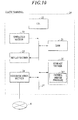
- Fig. 10 shows a configuration of the client terminal 20.
- the client terminal 20 includes the CPU 21, the operation section 22, the display section 23, the communication section 24, the Random Access Memory (RAM) 25, and the storage section 26 which are connected to one another through the bus 27.
- RAM Random Access Memory
- the CPU 21 reads the various processing programs stored in the storage section 26 to expand the read programs in the work area formed in the RAM 25 to perform various processing in cooperation with the programs, according to the operation signal input from the operation section 22 or the instruction signal received by the communication section 24.
- the operation section 22 is equipped with a key board including cursor keys, numeric keys and various function keys, and a pointing device such as a mouse.
- the operation section 22 outputs the instruction signal input by key operation on the key board or mouse operation, to the CPU 21.
- the display section 23 is composed of a Liquid Crystal Display (LCD), and displays the input instruction from the operation section 22, data, and the like, according to the instruction of the display signal input from the CPU 21.
- LCD Liquid Crystal Display
- the communication section 24 includes a LAN adaptor, router, TA, and the like, and transmits/receives the data to/from the external equipment such as the image forming apparatus 10 connected thereto through the communication network N.
- the RAM 25 forms the work area for temporarily storing the various processing programs to be executed by the CPU 21 and the data regarding these programs.
- the storage section 26 is a storage device composed of an HDD, semiconductor nonvolatile memory and the like, and stores the various programs, setting data, image data, and so on.
- the storage section 26 stores also a printer driver program 261.
- the CPU 21 reads the printer driver program 261 from the storage section 26 to expand the program in the RAM 25, and generates the print job to be transmitted to the image forming apparatus 10 in cooperation with the program. Then, the CPU 21 transmits the print job to the image forming apparatus 10 through the communication section 24.
- the CPU 21 specifies the image data (image file or document file) and the like to be printed based on user's operation performed through the operation section 22, and allows the display section 23 to display the printer driver screen 231 (see Figs. 12 and 13 ).
- the CPU 21 sets the information such as the number of sets (number of copies), print range, and printing method (duplex printing/single-side printing) based on the input signal from the operation section 22 to create the print job information.
- the CPU 21 creates the print job based on the print job information and the specified image data. This print job is transmitted to the image forming apparatus 10 through the communication section 24 by the CPU 21.
- the CPU 21 generates the feeding section information setting data to be sent to the image forming apparatus 10 in cooperation with the printer driver program 261.
- the CPU 21 then transmits the feeding section information setting data to the image forming apparatus 10 through the communication section 24.
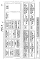
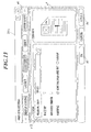
- the CPU 21 allows the display section 23 to display the printer driver screen 231 (see Fig. 11 ) based on user's operation performed through the operation section 22. Based on the input signal from the operation section 22, the CPU 21 creates the feeding section information setting data including sheet attribute information such as "sheet size”, “sheet type (obverse side)", “sheet type (reverse side)", “basis weight” and "colored sheet”. After that, the CPU 21 transmits this feeding section information setting data to the image forming apparatus 10 through the communication section 24.
- the feeding section information setting data is created as data corresponding to each of the feeding sections. For example, it is created as the feeding section information setting data regarding the first feeding section 18a, the feeding section information setting data regarding the second feeding section 18b, the feeding section information setting data regarding the third feeding section 18c, and the feeding section information setting data regarding the fourth feeding section 18d.
- Figs 11-13 show examples of the printer driver screen 231 to be displayed on the display section 23.
- Fig. 11 shows the printer driver screen 231a for setting the feeding section information
- Figs. 12 and 13 show the printer driver screens 231b, 231c for setting the print job information.
- each of the printer driver screens 231a-231c is composed of setting item selection region e6, information setting region e7, and so on.
- the setting item selection region e6 is a region for selecting the item to be set in the printer driver screen 231.
- the items such as "simple setting”, “layout”, “finish”, “sheet”, “cover sheet” and “page setting” are displayed. Any one of these items is selected based on user's operation.
- the information setting region e7 is a region for setting information regarding the item selected in the setting item selection region e6.
- the screen shown in Fig. 11 is displayed when the item "sheet” is selected.
- a tray/sheet information acquisition button b1, candidate value display button b2, and information for setting the feeding section information d2 are displayed.
- the sheet information such as "sheet size”, “sheet type (obverse side)", “sheet type (reverse side)", “basis weight”, "colored sheet” and "with hole” of each of the feeding sections (first-fourth feeding sections 18a-18d) is displayed.
- “with hole” corresponds to "punch hole”.
- the CPU 21 sends the feeding section information acquisition request to the image forming apparatus 10 through the communication section 24.
- the CPU 21 receives the feeding section information d2 from the image forming apparatus 10 to allow the RAM 25 to store the received information.
- the CPU 21 allows the display section 23 to display the sheet information of each of the feeding sections (first-fourth feeding sections 18a-18d) based on the feeding section information d2.
- the CPU 21 allows the feeding section information d2 to be an initial value of the feeding section information setting data.
- the candidate values settable with respect to the corresponding sheet information are displayed. For example, when depressing the candidate value display button b2 of "sheet type (obverse side)" of tray 1, “coated”, “additional printing”, “high-quality”, “plain”, “for book”, “rough” and “non-printing insertion” are displayed. Based on user's operation, any one of the candidate values is selected. When any one of the candidate values is selected, the CPU 21 sets the selected value to the feeding section information setting data to update the value. Moreover, the CPU 21 updates the information displayed in the information setting region e7.
- the CPU 21 transmits the feeding section information setting data to the image forming apparatus 10 through the communication section 24.
- sheet type (obverse side) is the obverse side information indicating the attribute specific to the obverse side of the print sheet
- sheet type (reverse side) is the reverse side information indicating the attribute specific to the reverse side of the print sheet
- sheet size is the common information indicating the attribute of the print sheet itself.
- a user does not need to input settings of the obverse side and the reverse side separately with respect to the attribute of the print sheet itself, namely the items “basis weight”, “colored sheet” and “with hole” regarding the common attribute between the obverse side and the reverse side.
- a user needs to input settings separately only with respect to the item “sheet information” (“sheet information (obverse side)” and “sheet information (reverse side)”) regarding the attribute specific to the obverse and reverse sides.
- the CPU 21 By checking/unchecking the check box in the printing method setting region e71 based on user's operation, the CPU 21 performs setting of "printing method" of the print job information d1.
- the CPU 21 When an OK button b3 or the apply button b4 is depressed based on user's operation, the CPU 21 reflects "printing method" and other items in the print job information d1 to be transmitted to the image forming apparatus 10.
- the screen shown in Fig. 13 is displayed when the item "finish" is selected in the setting item selection region e6.
- the feeding section selection region e72 which is a region for selecting the feeding section 18 (first-fourth feeding sections 18a-18d) and the like is displayed.
- the CPU 21 When any one of the first feeding section 18a (tray 1), the second feeding section 18b (tray 2), the third feeding section 18c (tray 3), the fourth feeding section 18d (tray 4), and automatic is selected on the feeding section selection region e72 based on user's operation, the CPU 21 reflects the value of the feeding section information d2 (first-fourth feeding section information d21-d24) of the selected feeding section 18 in the print job information d1 to be transmitted to the image forming apparatus 10. Incidentally, the CPU 21 sends the feeding section information acquisition request to the image forming apparatus 10 through the communication section 10 to obtain the feeding section information d2.
- the CPU 21 transmits the print job including the print job information d1 set in the printer driver screens 231b, 231c and the like to the image forming apparatus 10 through the communication section 24 to perform image forming processing.
- the print job to be transmitted to the image forming apparatus 10 includes the print job information containing information indicating the coated sheet as the attribute specific to the obverse side of the print sheet, and information indicating the plain sheet as the attribute specific to the reverse side of the sheet.
- Fig. 14 is a flowchart showing the series of processing regarding image formation. Incidentally, the flowchart is provided on the assumption that the print job is transmitted from the client terminal 20.
- Step S2 when the CPU 111 receives the print job with the communication I/F section 114 from the client terminal 20 (Step S1; YES), the print job is analyzed (Step S2).
- Step S3 the CPU 111 judges whether the printing side being processed is the obverse side or the reverse side (Step S4).
- Step S4 the CPU 111 controls image forming processing based on the obverse side information and the common information which are included in the print job information d1, the print control condition information d3 (see Fig. 5 ) stored in the RAM 112, and so on (Step S5).
- the CPU 111 sets "coated” which is the value of "sheet information (obverse side)” of the obverse side information among “sheet type (obverse side)” and “sheet type (reverse side)” as the value of "sheet type”. Then, the CPU 111 refers to the print control condition information (see Fig. 5 ) to output the instruction regarding the print control to each of the function sections based on each parameter value in the case that "sheet type” is “coated” and "basis weight” of the common information is "62-71g/ m 2 ". Each of the function sections executes processing regarding the print control according to the instruction sent from the CPU 111.
- the parameter values become as follows: “fixing temperature” is 150 C °, “transfer current” is 10 ⁇ A, “separation DC voltage” is 500V, and "feeding assisting fan” is on.
- Step S4 when the printing side is the reverse side (Step S4; NO), the CPU 111 controls image forming processing based on the reverse side information and the common information which are included in the print job information d1, and the print control condition information d3 stored in the RAM 112, and so on (Step S6).
- the CPU 111 sets "plain” which is the value of “sheet information (reverse side)” of the reverse side information among “sheet type (obverse side)” and “sheet type (reverse side)” as the value of "sheet type”. Then, the CPU 111 refers to the print control condition information (see Fig. 5 ) to output the instruction regarding the print control to each of the function sections based on each parameter in the case that "sheet type” is “plain” and “basis weight” of the common information is ""62-71g/ m 2 ". Each of the function sections executes processing regarding the print control (image formation control) according to the instruction transmitted from the CPU 111.
- the parameter values become as follows: “fixing temperature” is 160 C °, “transfer current” is 20 ⁇ A, “separation DC voltage” is 500V, and "feeding assisting fan” is off.
- Step S5 When processing in Steps S5, S6 ends, the CPU 111 judges whether or not there is the image data of next page to be printed. In other words, the CPU 11 judges whether or not the printing has completed (Step S8).
- Step S8 When judging that the printing has completed (Step S8; YES), the CPU 111 ends the series of processing regarding image formation. On the other hand, when judging that the printing has not completed (Step S8; NO), the CPU 111 judges whether the printing side of next print sheet is the obverse side or the reverse side (Step S4). Then, the CPU 111 continues the series of processing regarding image formation.
- Step S3 the CPU 111 controls image forming processing based on the obverse side information and the common information which are included in the print job information d1, and the print control condition information d3 stored in the RAM 112, and so on (Step S7).
- Step S7 When processing in Step S7 ends, the CPU 111 judges whether or not there is the image data of next page to be printed. In other words, the CPU 11 judges whether or not the printing has completed (Step S9).
- Step S9 When judging that the printing has completed (YES), the CPU 111 ends the series of processing regarding image formation. On the other hand, when judging that the printing has not completed (Step S9; NO), the CPU 111 controls image forming processing of next page based on the obverse side information and the common information which are included in the print job information d1, and the print control condition information d3 stored in the RAM 112, and so on (Step S7).
- the image forming apparatus 10 stores the obverse side information ("sheet type (obverse side)”) indicating the attribute specific to the obverse side of the sheet, the reverse side information (“sheet type (reverse side)”) indicating the attribute specific to the reverse side of the sheet, and the common information (“sheet size", “basis weight” and “punch hole”) indicating the attribute of the sheet itself, as the feeding section information d2, in the RAM 112 and the storage section 113.
- the image forming apparatus 10 When duplex printing is performed based on the print job, the image forming apparatus 10 reads corresponding image forming condition ("fixing temperature”, "transfer current” and the like) from the print control condition information d3 based on the obverse side information and the common information, and performs image forming processing on the obverse side of the sheet specified in the print job based on the read image forming condition. Then, the image forming apparatus 10 reads corresponding image forming condition from the print control condition information d3 based on the reverse side information and the common information, and performs image forming processing on the reverse side of the sheet specified in the print job based on the read image forming condition.
- image forming condition "fixing temperature”, "transfer current” and the like
- a user performs inputting for setting the feeding section information d2 on the feeding section information setting screen 151 or the printer driver screen 231a prior to image forming processing on both sides of the sheet whose obverse side and reverse side have different attributes from each other.
- image forming processing is performed on both sides of the sheet whose obverse side and reverse side have different attributes from each other
- a user performs inputting for setting the print job information d1 of duplex printing from the print job information inputting screen 152 or the printer driver screens 231b, 231c to allow the image forming apparatus 10 to perform image forming processing.
- it becomes unnecessary for a user to reset the sheet for each of the sides or to input again the attribute (sheet information) of the sheet and thereby work efficiency can be improved.
- nonvolatile memory such as a flash memory
- portable recording medium such as a CD-ROM
- carrier wave may be adopted as a medium providing data of the program through communication lines.
Landscapes
- Physics & Mathematics (AREA)
- General Physics & Mathematics (AREA)
- Accessory Devices And Overall Control Thereof (AREA)
- Record Information Processing For Printing (AREA)
- Control Or Security For Electrophotography (AREA)
- Facsimiles In General (AREA)
Abstract
Description
- The present invention relates to an image forming apparatus and a print instruction apparatus.
- An image forming apparatus such as Multifunction Peripheral (MFP) previously receives an input of sheet information (such as paper quality, color, basis weight of a sheet) of a print sheet to be image-formed so as to switch a control of image forming processing based on the sheet information, and thereby a jam is reduced and image quality is improved.
- In recently years, there has been widely used an image forming apparatus which automatically detects the sheet information of the print sheet to switch the control of image forming processing based on the detected sheet information. For example, there has been known an image forming apparatus of an electrophotography system which changes a fixing temperature between cases of plain sheet and thick sheet (Japanese Patent Application Laid-Open Publication No.
Hei 5-27642 - By the way, when duplex printing is performed on a print sheet (for example, a print sheet where types of sheet processing of the obverse side and reverse side are different from each other) whose obverse side and reverse side have different attributes from each other, an image forming apparatus can accept only one-side sheet information. Thus, when each of the obverse side and reverse side needs to be image-formed in most appropriate conditions, a user would have to perform the following operations.
- Specifically, the user firstly inputs the sheet information of the obverse side into the image forming apparatus. Secondly, the user allows the image forming apparatus to perform single-side printing on the obverse side of the print sheet. Next, the user inputs the sheet information of the reverse side into the image forming apparatus. Then, the user allows the image forming apparatus to perform single-side printing on the reverse side of the print sheet.
- However, when the image forming processing is performed on both sides of the sheet whose obverse side and reverse side have different attributes from each other (i.e., when duplex printing is performed), the user needs to reset the print sheet on which single-side printing has been performed in a feeding section again, and to input the sheet information again. As result, user's working efficiency is lowered.
- The prevent invention has been achieved in view of the abovementioned problems, and the object of the present invention is to improve user's working efficiency when image forming processing is performed on both sides of a sheet whose obverse side and reverse side have different attributes from each other.
- To achieve at least one of the abovementioned objects, according to one aspect of the present invention, there is provided an image forming apparatus to perform image forming processing based on a print job, which image forming apparatus including: a storage section to store obverse side information indicating an attribute specific to an obverse side of a sheet and reverse side information indicating an attribute specific to a reverse side of the sheet; and a control section to perform image forming processing on the obverse side of the sheet in an image forming condition according to the obverse side information stored in the storage section, and to perform image forming processing on the reverse side of the sheet in an image forming condition according to the reverse side information stored in the storage section, when image forming processing is performed on both sides of the sheet based on the print job.
- Preferably, the storage section further stores common information indicating an attribute of the sheet itself, which attribute is common between the obverse side and the reverse side of the sheet, and the control section performs image forming processing on the obverse side of the sheet in an image forming condition according to the obverse side information and the common information which are stored in the storage section, and performs image forming processing on the reverse side of the sheet in an image forming condition according to the reverse side information and the common information which are stored in the storage section.
- Preferably, the image forming apparatus further includes: an operation section to receive the obverse side information, the reverse side information and the common information respectively, and wherein the control section allows the storage section to store the obverse information, the reverse information and the common information which are received by the operation section.
- Preferably, each item regarding the obverse side information and the reverse side information which are received by the operation section includes at least one of items regarding a type of sheet processing and a sheet color, and an item regarding the common information received by the operation section includes at least one of items regarding a basis weight of the sheet and presence/absence of a punch hole.
- Preferably, the image forming apparatus includes: a feeding section to feed the stored sheet, and wherein when image forming processing is performed on both sides of the sheet according to the print job, the control section specifies the sheet specified in the print job based on the obverse side information, the reverse side information, and the common information which are stored in the storage section, to supply the specified sheet to the feeding section.
- Moreover, according to one aspect of the present invention, there is provided a print instruction apparatus to transmit a print job to an image forming apparatus to allow the image forming apparatus to perform image formation, which print instruction apparatus including: a storage section to at least temporarily store obverse side information indicating an attribute specific to an obverse side of a sheet and reverse side information indicating an attribute specific to a reverse side of the sheet; and a control section to generate the print job including the obverse side information and the reverse side information to transmit the generated print job to the image forming apparatus when a user instructs to perform image formation on both sides of the sheet.
- Preferably, the storage section further stores common information indicating an attribute of the sheet itself, which is common between the obverse side and the reverse side of the sheet, and the control section generates, as the print job, a print job further including the common information.
- The present invention will become more fully understood from the detailed description given hereinbelow and the appended drawings, and thus are not intended as a definition of the limits of the present invention, and wherein;
-
FIG. 1 is a system configuration diagram of an image forming system; -
FIG. 2 is an apparatus configuration diagram of an image forming apparatus; -
FIG. 3 is a block diagram of the image forming apparatus; -
FIG. 4 is a data configuration diagram of print job information; -
FIG. 5 is a data configuration diagram of feeding section information; -
FIG. 6 is a data configuration diagram of print control condition information; -
FIG. 7 is an example of a feeding section information setting screen in the image forming apparatus; -
FIG. 8 is an example of a feeding section information setting screen in the image forming apparatus; -
FIG. 9 is an example of a print job information inputting screen in the image forming apparatus; -
FIG. 10 is a block diagram of a client terminal; -
FIG. 11 is an example of a printer driver screen; -
FIG. 12 is an example of a printer driver screen; -
FIG. 13 is an example of a printer driver screen; and -
FIG. 14 is a flowchart showing processing to be executed in the image forming apparatus. - Hereinafter, one embodiment of an image forming apparatus according to the present invention will be described with reference to the drawings.
-
Fig. 1 shows a system configuration of animage forming system 100. As shown inFig. 1 , theimage forming system 100 is composed of animage forming apparatus 10 and aclient terminal 20 which are data communicatably connected to each other through a communication network N such as a LAN. - The
image forming apparatus 10 is so-called Multifunction Peripheral (MFP) including a copying function, image reading function and printing function, and forms an image on a sheet based on a print job (print instruction) transmitted from theclient terminal 20, image data read by an image reading section such as a scanner provided in theimage forming apparatus 10, and so on. - The
client terminal 20 is so-called personal computer, includes a function to transmit the print job to theimage forming apparatus 10, and acts as a print instruction apparatus. Theclient terminal 20 is provided with a printer driver program (hereinafter referred to as simply printer driver in some cases) installed therein, and uses a function of the printer driver to create the print job including print condition data (print job information) to be applied in image formation, image data, and so on, to transmit the created print job to theimage forming apparatus 10. -
Fig. 2 shows a configuration of theimage forming apparatus 10. As shown inFig. 2 , theimage forming apparatus 10 is configured to include: acontrol section 11; an Auto Document Feeder (ADF) 12; animage reading section 13; anoperation section 14; adisplay section 15; animage outputting section 16; animage forming section 17; a first feeding section 18a; a second feeding section 18b; a third feeding section 18c; and a fourth feeding section 18d. - The ADF 12 is an automatic document feeding apparatus, and automatically conveys a single sheet or a plurality of sheets to the
image reading section 13. - The
image reading section 13 is a function section to optically read the image on the document placed on a document rest to create the image data. Specifically, theimage reading section 13 optically scans the document conveyed by theADF 12 through a contact glass, or optically scans the document placed on the platen glass, to read the image recorded on the document image by photoelectric conversion with a Charge-Coupled Device (CCD) image sensor to create the image data of the read image to output the created image data to theimage forming section 17. - The
image forming section 17 is a function section to form an image, and includes not-shown photoreceptor, transfer belt, fixer, various conveying belts and the like. Theimage forming section 17 forms the image on the print sheet based on the image data read by theimage reading section 13 or the print job transmitted through the communication I/F section to output the image to theimage outputting section 16. As an image forming method, a known image process such as an electrophotography system and electrostatic recording system may be used. Moreover, theimage forming section 17 is capable of forming the image on both sides, namely the obverse side and reverse side, of the print sheet. - The
control section 11 controls each of the function sections, and includes a Central Processing Unit (CPU), Random Access Memory (RAM), storage section and the like. The details will be described later. - The first feeding section 18a, the second feeding section 18b, the third feeding section 18c and the fourth feeding section 18d store the sheet (print sheet) and send forth the stored print to the
image forming section 17 respectively. Hereinafter the first-fourth feeding sections 18a-18d are referred to generically as afeeding section 18. - The
operation section 14 and thedisplay section 15 are integrally configured with operation input keys, touch panel and the like. Theoperation section 14 outputs operation signals including a depression signal corresponding to a depressed key, and a position signal corresponding to a pushed position on the touch panel, to thecontrol section 11. Moreover, thedisplay section 15 displays a feeding section information setting screen (seeFigs. 7 and8 ), a print job information inputting screen (seeFig. 9 ), and so on. - A user performs a setting operation of the feeding section information, setting operation of the print job information, starting operation of printing and the like to be hereinafter described, with the touch panel contributing the
operation section 14 and thedisplay section 15. - The
image outputting section 16 is a function section to perform finishing processing such as punching, stapling, and bookbinding on the sheet conveyed from theimage forming section 17 according to the instruction from thecontrol section 11 to output the processed sheet. -
Fig. 3 is a block diagram of thecontrol section 11 and each of the function sections. Thecontrol section 11 is configured to include aCPU 111,RAM 112,storage section 113 and communication I/F section 114 which are communicably connected to one another through a bus. In addition, each of the function sections constructing thecontrol section 11 is communicably connected to theADF 12,image reading section 13,operation section 14,display section 15,image outputting section 16,image forming section 17 andfeeding section 18 through the bus. The communication I/F section 114 is communicably connected to the communication network N such as a LAN. - The
CPU 111 reads various processing programs stored in thestorage section 113 to expand the programs in a work area formed in theRAM 112 to perform various processing in cooperation with the programs. For example, theCPU 111 integrally manages/controls theimage forming apparatus 10 by controlling an operation of each of the function sections, controlling data input/output among the function sections, and so on. The function sections are specifically the ADF12,image reading section 13,operation section 14,display section 15,image outputting section 16,image forming section 17 andfeeding section 18. TheCPU 111 analyzes the print job when receiving the print job to output instructions for image forming processing to each of the function sections. - The
RAM 112 is a section to temporarily store various pieces of data read by theimage reading section 13 or input from the communication I/F section 114. The stored data is processed by theCPU 111, and transferred to thestorage section 113 or theimage forming section 17 as necessary. - The
RAM 112 stores the print job. The print job is, for example, composed of print job information indicating a print condition and image data indicating the image to be printed. The image data is composed of four colors of cyan (C), yellow (Y), magenta (M) and black (B), for example. TheCPU 111 receives the print job from other communication equipments through the communication I/F section 114. Incidentally, the image data may be information read by theimage reading section 13, and the print job information may be information set by an input signal from theoperation section 14. When the communication I/F section 114 receives the print job, theCPU 111 allows theRAM 112 to store the print job. Incidentally, the print job may include, in place of the image data, the image to be printed in a file format such as Portable Document Format (PDF) and XML Paper Specification (XPS), or in Page Description Language (PDL) format such as PostScript (registered trademark) (PS) and Printer Control Language (PCL). -
Fig. 4 shows a data configuration of the print job information. The print job information d1 includes information such as "job ID", "user name", "job name", "the number of sets", "printing method", "sheet type (obverse side)", "sheet type (reverse side)", and "basis weight". The "printing method" is information indicating which of duplex printing or single-side printing is to be performed, and has a value of one of "both sides" and "single side". The "both sides" corresponds to duplex printing, and the "single side" corresponds to single-side printing. - The "sheet type (obverse side)" is information of a type of sheet processing on the obverse side of the print sheet, and the "sheet type (reverse side)" is information of a type of sheet processing on the reverse side of the print sheet. Each of pieces of the information includes values such as "plain", "coated" and "rough". The "plain" corresponds to a plain sheet, the "coated" corresponds to a coated sheet, and the "rough" corresponds to a rough sheet. When the value of "printing method" is "single side", the value of "sheet type (reverse side)" becomes invalid.
- The basis weight is print sheet weight per one square meter. While the "sheet type (obverse side)" is an attribute specific to the obverse side and the "sheet type (reverse side)" is an attribute specific to the reverse side, the "basis weight" is an attribute of the sheet itself. The attribute of sheet itself is common attribute between the obverse side and the reverse side.
- Reverting to
Fig. 3 , thestorage section 113 is composed of a Hard Disk Drive (HDD), a semiconductor nonvolatile memory, and so on. Thestorage section 113 stores a program for allowing theCPU 111 to control each of the function sections and information regarding processing function of theimage forming apparatus 10. These program and information are read as necessary by theCPU 111 to be executed/processed on theRAM 112. - For example, the
storage section 113 stores feeding section information d2 (seeFig. 5 ), print control condition information d3 (seeFig. 6 ), and the like. The feeding section information d2 is sheet information indicating the attribute of the print sheet stored in thefeeding section 18. The print control condition information d3 is information indicating a processing parameter (image forming condition) of print control (image forming processing) according to the attribute (sheet type and the like) of the print sheet. These feeding section information d2 and print control condition information d3 are read by theCPU 11 into theRAM 112 when theimage forming apparatus 10 is powered up to start. -
Fig. 5 shows a data configuration of the feeding section information d2. The feeding section information d2 includes: a first feeding section information d21 which is sheet information of the print sheet stored in the first feeding section 18a; a second feeding section information d22 which is sheet information of the print sheet stored in the second feeding section 18b; a third feeding section information d23 which is sheet information of the print sheet stored in the third feeding section 18c; and a fourth feeding section information d24 which is sheet information of the print sheet stored in the fourth feeding section 18d. Each of pieces of the first-fourth feeding section information d21-d24 includes sheet information such as "sheet size", "sheet type (obverse side)", "sheet type (reverse side)", "basis weight", "colored sheet", "punch hole", and so on. - The sheet information includes: obverse side information indicating the attribute specific to the obverse side of the sheet; reverse side information indicating the attribute specific to the reverse side of the sheet; and common information indicating the attribute of the sheet itself. As an example of the obverse side information, "sheet type (obverse side)" may be cited, as an example of the reverse side information, "sheet type (reverse side)" may be cited, and as examples of the common information, "sheet size", ""basis weight", "colored sheet", "punch hole" and the like may be cited.
-
Fig. 6 shows a part of the data configuration of the print control condition information d3. The print control condition information d3 shown inFig. 6 represents information such as "fixing temperature", "transfer current", "separation DC voltage" and "feeding assisting fan" per "basis weight" of the common information, depending on "sheet type (obverse side)" which is one of the pieces of the obverse side information, and "sheet type (reverse side)" which is one of the pieces of the reverse side information. TheCPU 111 transmits the instruction regarding the print control to each of the function sections based on these values. Specifically, theCPU 111 sends the instruction regarding the print control to theimage forming section 17 based on the corresponding values of "fixing temperature", "transfer current", and "separation DC voltage". TheCPU 111 further transmits the instruction regarding the print control to thefeeding section 18 based on the corresponding value of "feeding assisting fan". - For example, when "sheet type (obverse side)" or "sheet type (reverse side)" and "basis weight" which are included in the print job information d1 are "coated" and "72-91g/m 2" respectively, the
CPU 111 transmits the instruction to form the image in the condition that the fixing temperature is 150C°, the transfer current is 10µA, and the separation DC voltage is 500V to theimage forming section 17, and transmits the instruction to feed the print sheet while the feeding assisting fan is in on-state to thefeeding section 18. - On the other hand, when "sheet type (obverse side)" or "sheet type (reverse side)" and "basis weight" which are included in the print job information d1 are "plain" and "131-161 g/m 2" respectively, the
CPU 111 transmits the instruction to form the image in the condition that the fixing temperature is 165C°, the transfer current is 25µA, and the separation DC voltage is 400V to theimage forming section 17, and transmits the instruction to feed the print sheet while the feeding assisting fan is in off-state to thefeeding section 18. - Then, each of the function sections executes processing regarding the print control according to the instruction transmitted from the
CPU 111. - Reverting to
Fig. 3 , the communication I/F section 114 is composed of a LAN interface, modem, and so on, and is a function section to perform data communication with external equipment such as a server, client, other apparatuses, and the like through the communication network N and the like. The communication I/F section 114 receives feeding section information setting data, feeding section information acquisition request, print job and the like from the other communication equipment. - The
CPU 111 updates the value of the feeding section information d2 based on the feeding section information setting data when receiving the feeding section information setting data through the communication I/F section 114. Specifically, theCPU 111 updates items such as "sheet type (obverse side)", "sheet type (reverse side)", "basis weight", "colored sheet" and "punch hole" of the first feeding section information d21 stored in theRAM 112 and thestorage section 113 based on the feeding section information setting data when receiving the feeding section information setting data regarding the first feeding section 18a. - The
CPU 111 allows theRAM 112 to temporality store the print job when receiving the print job through the communication I/F section 114. Then, theCPU 111 performs on theRAM 112 converting processing to convert the image data included in the print job into print image data, which is capable of being image-formed on the print sheet in theimage forming section 17. Thestorage section 113 stores various programs for converting the image data into the print image data, and theCPU 111 reads necessary programs. - The
CPU 111 updates the value of the feeding section information d2 based on an input signal from theoperation section 14. Specifically, theCPU 111 updates the items such as "sheet type (obverse side)", "sheet type (reverse side)", "basis weight", "colored sheet" and "punch hole" of the first feeding section information d21 stored in theRAM 112 and thestorage section 113 based on the input signal when receiving an input signal indicating updating of the feed section information d2 regarding the first feeding section 18a. - The
CPU 111 receives the image data from theimage reading section 13 to create (set) the print job information based on the input signal from theoperation section 14, and then allows theRAM 112 to temporarily store the image data and the print job information as the print job. After that, theCPU 111 executes on theRAM 112 converting processing to convert the image data included in the print job into the print image data, which is capable of being image-formed on the print sheet in theimage forming section 17. - The
CPU 111 allows thedisplay section 15 to display feeding section information setting screen 151 (seeFigs. 7 and8 ) and print job information inputting screen 152 (seeFig. 9 ) based on the input signal from theoperation section 14. - The
CPU 111 transmits the feeding section information d2 stored in theRAM 112 to a source of the feeding section information acquisition request when receiving the feeding section information acquisition request through the communication I/F section 114. - Next,
Figs. 7 and8 show examples of the feeding sectioninformation setting screen 151 to be displayed on thedisplay section 15.Figs. 7 and8 show same screens. - As shown in
Figs. 7 and8 , the feeding sectioninformation setting screen 151 contains a setting item display region e1, setting value display region e2, candidate value display region e3 and the like. - In the setting item display region e1, a list of sheet information (obverse side information, reverse side information, and common information) included in the feeding section information d2 to be set on the feeding section
information setting screen 151 is displayed. Specifically, in the setting item display region e1, the setting items such as "sheet type (obverse side)", "sheet type (reverse side)", "basis weight", "colored sheet" and "punch hole" among the sheet information included in the feeding section information d2 are displayed. Any one of these setting items is selected based on user's operation. For example, "sheet type (obverse side)" of the obverse side information is selected inFig. 7 , and "basis weight" of the common information is selected inFig. 8 . - In the setting value display region e2, the value set with respect to the sheet information displayed in the setting item display region e1. For example, in
Figs 7 and8 , "coated" is set with respect to "sheet type (obverse side)", "plain" is set with respect to "sheet type (reverse type)", "62-71g/m 2" is set with respect to "basis weight", "white" is set with respect to "colored sheet", and "none" is set with respect to the "punch hole". - In the candidate value display region e3, candidate values settable with respect to the sheet information selected in the setting item display region e1 are displayed. For example, in
Fig. 7 , "coated", "additional printing", "high-quality", "plain", "for book", "rough", and "non-printed insertion" are displayed as candidate values settable with respect to "sheet type (obverse side)" selected in the setting item display region e1. InFig. 8 , "40-49g/m 2", "50-61g/m 2", "62-71g/m 2", "72-91g/m 2", "91-130g/m 2", "131-161g/m 2", "162-216g/m 2" and "217-244g/m 2" are displayed as candidate values settable with respect to "basis weight" selected in the setting item display region e1. Any one of these candidate values is selected based on user's operation. For example, "coated" is selected inFig. 7 , and "62-71-g/m 2" is selected inFig. 8 . When any one of candidate values is selected, theCPU 111 sets the selected value as the value of the sheet information selected in the setting item display region e1. Then, theCPU 111 reflects the set value of the sheet information in the setting value display region e2. - As described above, among the sheet information displayed in the setting item display region e1, "sheet type (obverse side)" is the obverse side information indicating the attribute specific to the obverse side of the print sheet, and "sheet type (reverse side)" is the reverse side information indicating the attribute specific to the reverse side of the print sheet. In addition, "basis weight", "colored sheet" and "punch hole" are common information indicating the attribute of the print sheet itself.
- Thus, a user can specify each of the attributes of the obverse side and reverse side with respect to the print sheet on the feeding section
information setting screen 151. Thus, the obverse side and the reverse side of the same print sheet can be registered individually. On the other hand, a user does not need to input settings of the obverse side and the reverse side separately with respect to the attribute of the print sheet itself, namely items "basis weight", "colored sheet" and "punch hole" regarding common attribute between the obverse side and the reverse side. In other words, a user needs to input setting separately only with respect to the item "sheet information ("sheet information (obverse side)" and "sheet information (reverse side)")" regarding the attributes specific to the obverse side and the reverse side. As a result, user's working efficiency is improved when image forming processing is performed on both sides of the print sheet whose obverse side and reverse side have different attributes from each other in most appropriate conditions. - Next,
Fig. 9 shows an example of the print jobinformation inputting screen 152 to be displayed on thedisplay section 15. - As shown in
Fig. 9 , the print jobinformation inputting screen 152 includes both sides/single side setting region e4, feeding section information display region e5, and so on. - The both sides/single side setting region e4 is a region for setting the value of "printing method" of the print job information d1.
- In the feeding section information display region e5, the values of the feeding section information d2 stored in the
RAM 112 and thestorage section 113 are displayed. TheCPU 111 displays the information in the feeding section information display region e5 based on the feeding section information d2 stored in theRAM 112 when receiving the input signal for displaying the print jobinformation input screen 152 from theoperation section 14. -
Fig. 10 shows a configuration of theclient terminal 20. As shown inFig. 10 , theclient terminal 20 includes theCPU 21, theoperation section 22, thedisplay section 23, thecommunication section 24, the Random Access Memory (RAM) 25, and thestorage section 26 which are connected to one another through thebus 27. - The
CPU 21 reads the various processing programs stored in thestorage section 26 to expand the read programs in the work area formed in theRAM 25 to perform various processing in cooperation with the programs, according to the operation signal input from theoperation section 22 or the instruction signal received by thecommunication section 24. - The
operation section 22 is equipped with a key board including cursor keys, numeric keys and various function keys, and a pointing device such as a mouse. Theoperation section 22 outputs the instruction signal input by key operation on the key board or mouse operation, to theCPU 21. - The
display section 23 is composed of a Liquid Crystal Display (LCD), and displays the input instruction from theoperation section 22, data, and the like, according to the instruction of the display signal input from theCPU 21. - The
communication section 24 includes a LAN adaptor, router, TA, and the like, and transmits/receives the data to/from the external equipment such as theimage forming apparatus 10 connected thereto through the communication network N. - The
RAM 25 forms the work area for temporarily storing the various processing programs to be executed by theCPU 21 and the data regarding these programs. - The
storage section 26 is a storage device composed of an HDD, semiconductor nonvolatile memory and the like, and stores the various programs, setting data, image data, and so on. Thestorage section 26 stores also aprinter driver program 261. - The
CPU 21 reads theprinter driver program 261 from thestorage section 26 to expand the program in theRAM 25, and generates the print job to be transmitted to theimage forming apparatus 10 in cooperation with the program. Then, theCPU 21 transmits the print job to theimage forming apparatus 10 through thecommunication section 24. - Specifically, the
CPU 21 specifies the image data (image file or document file) and the like to be printed based on user's operation performed through theoperation section 22, and allows thedisplay section 23 to display the printer driver screen 231 (seeFigs. 12 and13 ). TheCPU 21 then sets the information such as the number of sets (number of copies), print range, and printing method (duplex printing/single-side printing) based on the input signal from theoperation section 22 to create the print job information. After that, theCPU 21 creates the print job based on the print job information and the specified image data. This print job is transmitted to theimage forming apparatus 10 through thecommunication section 24 by theCPU 21. - The
CPU 21 generates the feeding section information setting data to be sent to theimage forming apparatus 10 in cooperation with theprinter driver program 261. TheCPU 21 then transmits the feeding section information setting data to theimage forming apparatus 10 through thecommunication section 24. - Specifically, the
CPU 21 allows thedisplay section 23 to display the printer driver screen 231 (seeFig. 11 ) based on user's operation performed through theoperation section 22. Based on the input signal from theoperation section 22, theCPU 21 creates the feeding section information setting data including sheet attribute information such as "sheet size", "sheet type (obverse side)", "sheet type (reverse side)", "basis weight" and "colored sheet". After that, theCPU 21 transmits this feeding section information setting data to theimage forming apparatus 10 through thecommunication section 24. - Incidentally, the feeding section information setting data is created as data corresponding to each of the feeding sections. For example, it is created as the feeding section information setting data regarding the first feeding section 18a, the feeding section information setting data regarding the second feeding section 18b, the feeding section information setting data regarding the third feeding section 18c, and the feeding section information setting data regarding the fourth feeding section 18d.
- Next,
Figs 11-13 show examples of the printer driver screen 231 to be displayed on thedisplay section 23.Fig. 11 shows theprinter driver screen 231a for setting the feeding section information, andFigs. 12 and13 show theprinter driver screens - As shown in
Figs. 11-13 , each of theprinter driver screens 231a-231c is composed of setting item selection region e6, information setting region e7, and so on. - The setting item selection region e6 is a region for selecting the item to be set in the printer driver screen 231. In the setting item selection region e6, the items such as "simple setting", "layout", "finish", "sheet", "cover sheet" and "page setting" are displayed. Any one of these items is selected based on user's operation.
- The information setting region e7 is a region for setting information regarding the item selected in the setting item selection region e6.
- The screen shown in
Fig. 11 is displayed when the item "sheet" is selected. As shown inFig. 11 , in the information setting region e7, a tray/sheet information acquisition button b1, candidate value display button b2, and information for setting the feeding section information d2 are displayed. Specifically, in the information setting region e7, the sheet information such as "sheet size", "sheet type (obverse side)", "sheet type (reverse side)", "basis weight", "colored sheet" and "with hole" of each of the feeding sections (first-fourth feeding sections 18a-18d) is displayed. Incidentally, "with hole" corresponds to "punch hole". - When the tray/sheet information acquisition button b1 is depressed by user's operation, the
CPU 21 sends the feeding section information acquisition request to theimage forming apparatus 10 through thecommunication section 24. TheCPU 21 receives the feeding section information d2 from theimage forming apparatus 10 to allow theRAM 25 to store the received information. Then, theCPU 21 allows thedisplay section 23 to display the sheet information of each of the feeding sections (first-fourth feeding sections 18a-18d) based on the feeding section information d2. TheCPU 21 allows the feeding section information d2 to be an initial value of the feeding section information setting data. - When the candidate value display button b2 of each of pieces of the sheet information is depressed by user's operation, the candidate values settable with respect to the corresponding sheet information are displayed. For example, when depressing the candidate value display button b2 of "sheet type (obverse side)" of
tray 1, "coated", "additional printing", "high-quality", "plain", "for book", "rough" and "non-printing insertion" are displayed. Based on user's operation, any one of the candidate values is selected. When any one of the candidate values is selected, theCPU 21 sets the selected value to the feeding section information setting data to update the value. Moreover, theCPU 21 updates the information displayed in the information setting region e7. - When an OK button b3 or an apply button b4 is depressed by user's operation, the
CPU 21 transmits the feeding section information setting data to theimage forming apparatus 10 through thecommunication section 24. - As described above, among pieces of the sheet information displayed in the information setting region e7, "sheet type (obverse side)" is the obverse side information indicating the attribute specific to the obverse side of the print sheet, and "sheet type (reverse side)" is the reverse side information indicating the attribute specific to the reverse side of the print sheet. In addition, "sheet size", "basis weight", "colored sheet" and "with hole" are the common information indicating the attribute of the print sheet itself.
- Thus, on the
printer driver screen 231a, a user does not need to input settings of the obverse side and the reverse side separately with respect to the attribute of the print sheet itself, namely the items "basis weight", "colored sheet" and "with hole" regarding the common attribute between the obverse side and the reverse side. In other words, a user needs to input settings separately only with respect to the item "sheet information" ("sheet information (obverse side)" and "sheet information (reverse side)") regarding the attribute specific to the obverse and reverse sides. Thus, user's work efficiency when image forming processing is performed on both sides of the print sheet whose obverse side and reverse side have different attributes from each other can be improved - The screen shown in
Fig. 12 is displayed when the item "layout" is selected in the setting item selection region e6. As shown inFig. 12 , in the information setting region e7, the printing method setting region e71 which is a region for setting the value of "printing method" of the print job information d1 and the like is displayed. - By checking/unchecking the check box in the printing method setting region e71 based on user's operation, the
CPU 21 performs setting of "printing method" of the print job information d1. - When an OK button b3 or the apply button b4 is depressed based on user's operation, the
CPU 21 reflects "printing method" and other items in the print job information d1 to be transmitted to theimage forming apparatus 10. - The screen shown in
Fig. 13 is displayed when the item "finish" is selected in the setting item selection region e6. As shown inFig. 13 , in the information setting region e7, the feeding section selection region e72 which is a region for selecting the feeding section 18 (first-fourth feeding sections 18a-18d) and the like is displayed. - When any one of the first feeding section 18a (tray 1), the second feeding section 18b (tray 2), the third feeding section 18c (tray 3), the fourth feeding section 18d (tray 4), and automatic is selected on the feeding section selection region e72 based on user's operation, the
CPU 21 reflects the value of the feeding section information d2 (first-fourth feeding section information d21-d24) of the selectedfeeding section 18 in the print job information d1 to be transmitted to theimage forming apparatus 10. Incidentally, theCPU 21 sends the feeding section information acquisition request to theimage forming apparatus 10 through thecommunication section 10 to obtain the feeding section information d2. - When not-shown print button is depressed by user's operation, the
CPU 21 transmits the print job including the print job information d1 set in theprinter driver screens image forming apparatus 10 through thecommunication section 24 to perform image forming processing. In other words, according to the example ofFig. 4 , the print job to be transmitted to theimage forming apparatus 10 includes the print job information containing information indicating the coated sheet as the attribute specific to the obverse side of the print sheet, and information indicating the plain sheet as the attribute specific to the reverse side of the sheet. - Next, specific operations of a series of processing regarding image formation performed by the
CPU 111 will be described with reference toFig. 14. Fig. 14 is a flowchart showing the series of processing regarding image formation. Incidentally, the flowchart is provided on the assumption that the print job is transmitted from theclient terminal 20. - Firstly, when the
CPU 111 receives the print job with the communication I/F section 114 from the client terminal 20 (Step S1; YES), the print job is analyzed (Step S2). - Specifically, the
CPU 111 refers to the value of "printing method" of the print job information d1 included in the print job. When the value of "printing method" is "both sides", theCPU 111 judges that image forming processing according to the print job is duplex printing (Step S3; YES). On the other hand, when the value of "printing method" is "single side", theCPU 111 judges that image forming processing according to the print job is single-side printing (Step S3; NO). - In the case of duplex printing (Step S3; YES), the
CPU 111 judges whether the printing side being processed is the obverse side or the reverse side (Step S4). - When the printing side is the obverse side (Step S4), the
CPU 111 controls image forming processing based on the obverse side information and the common information which are included in the print job information d1, the print control condition information d3 (seeFig. 5 ) stored in theRAM 112, and so on (Step S5). - Specifically, when explaining by the example of
Fig. 4 , theCPU 111 sets "coated" which is the value of "sheet information (obverse side)" of the obverse side information among "sheet type (obverse side)" and "sheet type (reverse side)" as the value of "sheet type". Then, theCPU 111 refers to the print control condition information (seeFig. 5 ) to output the instruction regarding the print control to each of the function sections based on each parameter value in the case that "sheet type" is "coated" and "basis weight" of the common information is "62-71g/m 2". Each of the function sections executes processing regarding the print control according to the instruction sent from theCPU 111. The parameter values become as follows: "fixing temperature" is 150C°, "transfer current" is 10µA, "separation DC voltage" is 500V, and "feeding assisting fan" is on. - On the other hand, when the printing side is the reverse side (Step S4; NO), the
CPU 111 controls image forming processing based on the reverse side information and the common information which are included in the print job information d1, and the print control condition information d3 stored in theRAM 112, and so on (Step S6). - Specifically, when explaining by the example of
Fig. 4 , theCPU 111 sets "plain" which is the value of "sheet information (reverse side)" of the reverse side information among "sheet type (obverse side)" and "sheet type (reverse side)" as the value of "sheet type". Then, theCPU 111 refers to the print control condition information (seeFig. 5 ) to output the instruction regarding the print control to each of the function sections based on each parameter in the case that "sheet type" is "plain" and "basis weight" of the common information is ""62-71g/m 2". Each of the function sections executes processing regarding the print control (image formation control) according to the instruction transmitted from theCPU 111. The parameter values become as follows: "fixing temperature" is 160C°, "transfer current" is 20µA, "separation DC voltage" is 500V, and "feeding assisting fan" is off. - When processing in Steps S5, S6 ends, the
CPU 111 judges whether or not there is the image data of next page to be printed. In other words, theCPU 11 judges whether or not the printing has completed (Step S8). - When judging that the printing has completed (Step S8; YES), the
CPU 111 ends the series of processing regarding image formation. On the other hand, when judging that the printing has not completed (Step S8; NO), theCPU 111 judges whether the printing side of next print sheet is the obverse side or the reverse side (Step S4). Then, theCPU 111 continues the series of processing regarding image formation. - Reverting to Step S3, in the case of one-side printing (Step S3; NO), the
CPU 111 controls image forming processing based on the obverse side information and the common information which are included in the print job information d1, and the print control condition information d3 stored in theRAM 112, and so on (Step S7). - When processing in Step S7 ends, the
CPU 111 judges whether or not there is the image data of next page to be printed. In other words, theCPU 11 judges whether or not the printing has completed (Step S9). - When judging that the printing has completed (Step S9; YES), the
CPU 111 ends the series of processing regarding image formation. On the other hand, when judging that the printing has not completed (Step S9; NO), theCPU 111 controls image forming processing of next page based on the obverse side information and the common information which are included in the print job information d1, and the print control condition information d3 stored in theRAM 112, and so on (Step S7). - As described above, according to the embodiment, the
image forming apparatus 10 stores the obverse side information ("sheet type (obverse side)") indicating the attribute specific to the obverse side of the sheet, the reverse side information ("sheet type (reverse side)") indicating the attribute specific to the reverse side of the sheet, and the common information ("sheet size", "basis weight" and "punch hole") indicating the attribute of the sheet itself, as the feeding section information d2, in theRAM 112 and thestorage section 113. - When duplex printing is performed based on the print job, the
image forming apparatus 10 reads corresponding image forming condition ("fixing temperature", "transfer current" and the like) from the print control condition information d3 based on the obverse side information and the common information, and performs image forming processing on the obverse side of the sheet specified in the print job based on the read image forming condition. Then, theimage forming apparatus 10 reads corresponding image forming condition from the print control condition information d3 based on the reverse side information and the common information, and performs image forming processing on the reverse side of the sheet specified in the print job based on the read image forming condition. - As a result, in the case that image forming processing is performed on both sides of the sheet where the obverse side and the reverse side have different attributes from each other, user's work efficiency can be improved.
- Specifically, a user performs inputting for setting the feeding section information d2 on the feeding section
information setting screen 151 or theprinter driver screen 231a prior to image forming processing on both sides of the sheet whose obverse side and reverse side have different attributes from each other. When image forming processing is performed on both sides of the sheet whose obverse side and reverse side have different attributes from each other, a user performs inputting for setting the print job information d1 of duplex printing from the print jobinformation inputting screen 152 or theprinter driver screens image forming apparatus 10 to perform image forming processing. As result, it becomes unnecessary for a user to reset the sheet for each of the sides or to input again the attribute (sheet information) of the sheet, and thereby work efficiency can be improved. - In addition, the description of the above embodiment is an example of the image forming apparatus according to the present invention, and the present invention is not limited to the embodiment. Also detailed configuration and detailed operation of each of the function sections which constitute the image forming apparatus may be properly changed.
- Although the abovementioned embodiment discloses the example in which the ROM and HDD are used as computer-readable media storing the program, the present invention is not limited to the example. As other computer readable medium, nonvolatile memory such as a flash memory, a portable recording medium such as a CD-ROM may be adopted.
- In addition, also carrier wave may be adopted as a medium providing data of the program through communication lines.
Claims (7)
- An image forming apparatus to perform image forming processing based on a print job, which image forming apparatus comprising:a storage section to store obverse side information indicating an attribute specific to an obverse side of a sheet and reverse side information indicating an attribute specific to a reverse side of the sheet; anda control section to perform image forming processing on the obverse side of the sheet in an image forming condition according to the obverse side information stored in the storage section, and to perform image forming processing on the reverse side of the sheet in an image forming condition according to the reverse side information stored in the storage section, when image forming processing is performed on both sides of the sheet based on the print job.
- The image forming apparatus of claim 1, wherein
the storage section further stores common information indicating an attribute of the sheet itself, which attribute is common between the obverse side and the reverse side of the sheet, and
the control section performs image forming processing on the obverse side of the sheet in an image forming condition according to the obverse side information and the common information which are stored in the storage section, and performs image forming processing on the reverse side of the sheet in an image forming condition according to the reverse side information and the common information which are stored in the storage section. - The image forming apparatus of claim 2 further comprising:an operation section to receive the obverse side information, the reverse side information and the common information respectively, and whereinthe control section allows the storage section to store the obverse information, the reverse information and the common information which are received by the operation section.
- The image forming apparatus of claim 3 wherein
each item regarding the obverse side information and the reverse side information which are received by the operation section includes at least one of items regarding a type of sheet processing and a sheet color, and
an item regarding the common information received by the operation section includes at least one of items regarding a basis weight of the sheet and presence/absence of a punch hole. - The image forming apparatus of any of claims 2-4 further comprising:a feeding section to feed the stored sheet, and whereinwhen image forming processing is performed on both sides of the sheet according to the print job, the control section specifies the sheet specified in the print job based on the obverse side information, the reverse side information, and the common information which are stored in the storage section, to supply the specified sheet to the feeding section.
- A print instruction apparatus to transmit a print job to an image forming apparatus to allow the image forming apparatus to perform image formation, which print instruction apparatus comprising:a storage section to at least temporarily store obverse side information indicating an attribute specific to an obverse side of a sheet and reverse side information indicating an attribute specific to a reverse side of the sheet; anda control section to generate the print job including the obverse side information and the reverse side information to transmit the generated print job to the image forming apparatus when a user instructs to perform image formation on both sides of the sheet.
- The print instruction apparatus of claim 6, wherein
the storage section further stores common information indicating an attribute of the sheet itself, which attribute is common between the obverse side and the reverse side of the sheet, and
the control section generates, as the print job, a print job further including the common information.
Applications Claiming Priority (1)
| Application Number | Priority Date | Filing Date | Title |
|---|---|---|---|
| JP2008188396A JP2010023363A (en) | 2008-07-22 | 2008-07-22 | Image formation device, print instruction apparatus and program |
Publications (2)
| Publication Number | Publication Date |
|---|---|
| EP2148250A2 true EP2148250A2 (en) | 2010-01-27 |
| EP2148250A3 EP2148250A3 (en) | 2011-06-08 |
Family
ID=41361322
Family Applications (1)
| Application Number | Title | Priority Date | Filing Date |
|---|---|---|---|
| EP09165427A Withdrawn EP2148250A3 (en) | 2008-07-22 | 2009-07-14 | Image forming apparatus and print instruction apparatus |
Country Status (4)
| Country | Link |
|---|---|
| US (1) | US20100020342A1 (en) |
| EP (1) | EP2148250A3 (en) |
| JP (1) | JP2010023363A (en) |
| CN (1) | CN101635780B (en) |
Families Citing this family (5)
| Publication number | Priority date | Publication date | Assignee | Title |
|---|---|---|---|---|
| JP5237245B2 (en) * | 2009-11-30 | 2013-07-17 | キヤノン株式会社 | Printing apparatus, printing apparatus control method, and program |
| JP5637443B2 (en) * | 2010-11-29 | 2014-12-10 | 株式会社リコー | Image forming apparatus |
| JP2012218298A (en) * | 2011-04-08 | 2012-11-12 | Canon Inc | Printer, print control method, and program |
| JP6019841B2 (en) * | 2012-07-09 | 2016-11-02 | 富士ゼロックス株式会社 | Information processing apparatus and information processing program |
| JP6235774B2 (en) * | 2012-10-24 | 2017-11-22 | キヤノン株式会社 | Printing apparatus and control method and program therefor |
Citations (1)
| Publication number | Priority date | Publication date | Assignee | Title |
|---|---|---|---|---|
| JPH0527642A (en) | 1991-07-19 | 1993-02-05 | Tokyo Electric Co Ltd | Electrophotographic copying |
Family Cites Families (12)
| Publication number | Priority date | Publication date | Assignee | Title |
|---|---|---|---|---|
| JP2000231152A (en) * | 1999-02-12 | 2000-08-22 | Hitachi Software Eng Co Ltd | Automatic photographing device and printing paper |
| JP2001130068A (en) * | 1999-11-08 | 2001-05-15 | Canon Inc | Image forming system, image forming method, and storage medium |
| JP3667183B2 (en) * | 2000-01-28 | 2005-07-06 | キヤノン株式会社 | Printing apparatus and print medium type discrimination method |
| JP5147152B2 (en) * | 2001-08-06 | 2013-02-20 | キヤノン株式会社 | Duplex printing device |
| JP2005186335A (en) * | 2003-12-24 | 2005-07-14 | Konica Minolta Business Technologies Inc | Image forming apparatus |
| JP2007025775A (en) * | 2005-07-12 | 2007-02-01 | Fujifilm Holdings Corp | Image processor and image processing program |
| JP4551835B2 (en) * | 2005-07-28 | 2010-09-29 | キヤノン株式会社 | Information processing apparatus, information processing method, and print control program |
| JP4892887B2 (en) * | 2005-08-12 | 2012-03-07 | 富士ゼロックス株式会社 | Image forming apparatus and control method thereof |
| KR100683408B1 (en) * | 2006-02-03 | 2007-02-22 | 삼성전자주식회사 | Image Forming Device |
| JP4775150B2 (en) * | 2006-07-19 | 2011-09-21 | ブラザー工業株式会社 | Image forming apparatus |
| JP2008087419A (en) * | 2006-10-04 | 2008-04-17 | Konica Minolta Business Technologies Inc | Image formation device, image forming system and program |
| JP2009202575A (en) * | 2008-01-29 | 2009-09-10 | Ricoh Co Ltd | Image forming apparatus, medium feed control method and computer program |
-
2008
- 2008-07-22 JP JP2008188396A patent/JP2010023363A/en active Pending
-
2009
- 2009-07-14 EP EP09165427A patent/EP2148250A3/en not_active Withdrawn
- 2009-07-17 US US12/504,707 patent/US20100020342A1/en not_active Abandoned
- 2009-07-22 CN CN200910164763.9A patent/CN101635780B/en active Active
Patent Citations (1)
| Publication number | Priority date | Publication date | Assignee | Title |
|---|---|---|---|---|
| JPH0527642A (en) | 1991-07-19 | 1993-02-05 | Tokyo Electric Co Ltd | Electrophotographic copying |
Also Published As
| Publication number | Publication date |
|---|---|
| CN101635780A (en) | 2010-01-27 |
| CN101635780B (en) | 2013-04-24 |
| EP2148250A3 (en) | 2011-06-08 |
| US20100020342A1 (en) | 2010-01-28 |
| JP2010023363A (en) | 2010-02-04 |
Similar Documents
| Publication | Publication Date | Title |
|---|---|---|
| JP6150078B2 (en) | Image forming apparatus, image forming system, and image forming control method | |
| US8649035B2 (en) | Image processor, printing system, computer readable medium, and image processing method for resuming an interrupted printing process | |
| US20100306646A1 (en) | Image processing apparatus and computer-readable storage medium | |
| EP2148250A2 (en) | Image forming apparatus and print instruction apparatus | |
| US8599429B2 (en) | Control program and image forming apparatus | |
| US8014008B2 (en) | Control apparatus, control method therefor, and printing system | |
| US8472036B2 (en) | Controlling program and controlling method | |
| JP6435951B2 (en) | Image generation apparatus, control program for image generation apparatus, and control method for image generation apparatus. | |
| US20090230607A1 (en) | Image forming apparatus and computer program product | |
| US20130155455A1 (en) | Printing system, printing apparatus, image processing apparatus, and data conversion method | |
| US8705088B2 (en) | Image processing apparatus including an input section and a generating section for printing image data, printing system, and computer readable medium | |
| JP4387285B2 (en) | Printing apparatus, printing control method, printing control program, and recording medium for recording printing control program | |
| US20090103138A1 (en) | Image forming indicating terminal and image forming indicating method | |
| JP5814529B2 (en) | Printing system, paper attribute setting method, program | |
| US8405872B2 (en) | Method and apparatus for printing on custom media using an image production device | |
| US8396381B2 (en) | Methods and apparatuses for applying respective EP engine settings to different zones within a page of media | |
| CN108081771A (en) | Printing equipment and control method | |
| US20090135442A1 (en) | Scanning device having virtual trays into which media sheets are loaded for printing copy jobs initiated at the scanning device | |
| JP2012131129A (en) | Image forming apparatus | |
| JP2011137955A (en) | Printing system, printer and printing method, and program for performing printing method | |
| JP2010219867A (en) | Print job processing apparatus and image processing system | |
| JP2017042940A (en) | Image processing apparatus, information processing apparatus, information processing method, and program | |
| US20080190308A1 (en) | Image forming apparatus and computer-readable medium | |
| JP2006031479A (en) | Image forming apparatus | |
| JP2010114749A (en) | Image forming apparatus |
Legal Events
| Date | Code | Title | Description |
|---|---|---|---|
| PUAI | Public reference made under article 153(3) epc to a published international application that has entered the european phase |
Free format text: ORIGINAL CODE: 0009012 |
|
| AK | Designated contracting states |
Kind code of ref document: A2 Designated state(s): AT BE BG CH CY CZ DE DK EE ES FI FR GB GR HR HU IE IS IT LI LT LU LV MC MK MT NL NO PL PT RO SE SI SK SM TR |
|
| AX | Request for extension of the european patent |
Extension state: AL BA RS |
|
| PUAL | Search report despatched |
Free format text: ORIGINAL CODE: 0009013 |
|
| AK | Designated contracting states |
Kind code of ref document: A3 Designated state(s): AT BE BG CH CY CZ DE DK EE ES FI FR GB GR HR HU IE IS IT LI LT LU LV MC MK MT NL NO PL PT RO SE SI SK SM TR |
|
| AX | Request for extension of the european patent |
Extension state: AL BA RS |
|
| STAA | Information on the status of an ep patent application or granted ep patent |
Free format text: STATUS: THE APPLICATION IS DEEMED TO BE WITHDRAWN |
|
| 18D | Application deemed to be withdrawn |
Effective date: 20111209 |