EP2148093A1 - Screw compressor - Google Patents
Screw compressor Download PDFInfo
- Publication number
- EP2148093A1 EP2148093A1 EP08752382A EP08752382A EP2148093A1 EP 2148093 A1 EP2148093 A1 EP 2148093A1 EP 08752382 A EP08752382 A EP 08752382A EP 08752382 A EP08752382 A EP 08752382A EP 2148093 A1 EP2148093 A1 EP 2148093A1
- Authority
- EP
- European Patent Office
- Prior art keywords
- rotor
- gas
- screw
- outlet side
- seal surface
- Prior art date
- Legal status (The legal status is an assumption and is not a legal conclusion. Google has not performed a legal analysis and makes no representation as to the accuracy of the status listed.)
- Granted
Links
Images




Classifications
-
- F—MECHANICAL ENGINEERING; LIGHTING; HEATING; WEAPONS; BLASTING
- F04—POSITIVE - DISPLACEMENT MACHINES FOR LIQUIDS; PUMPS FOR LIQUIDS OR ELASTIC FLUIDS
- F04C—ROTARY-PISTON, OR OSCILLATING-PISTON, POSITIVE-DISPLACEMENT MACHINES FOR LIQUIDS; ROTARY-PISTON, OR OSCILLATING-PISTON, POSITIVE-DISPLACEMENT PUMPS
- F04C18/00—Rotary-piston pumps specially adapted for elastic fluids
- F04C18/48—Rotary-piston pumps with non-parallel axes of movement of co-operating members
- F04C18/50—Rotary-piston pumps with non-parallel axes of movement of co-operating members the axes being arranged at an angle of 90 degrees
- F04C18/52—Rotary-piston pumps with non-parallel axes of movement of co-operating members the axes being arranged at an angle of 90 degrees of intermeshing engagement type, i.e. with engagement of co-operating members similar to that of toothed gearing
-
- F—MECHANICAL ENGINEERING; LIGHTING; HEATING; WEAPONS; BLASTING
- F04—POSITIVE - DISPLACEMENT MACHINES FOR LIQUIDS; PUMPS FOR LIQUIDS OR ELASTIC FLUIDS
- F04C—ROTARY-PISTON, OR OSCILLATING-PISTON, POSITIVE-DISPLACEMENT MACHINES FOR LIQUIDS; ROTARY-PISTON, OR OSCILLATING-PISTON, POSITIVE-DISPLACEMENT PUMPS
- F04C27/00—Sealing arrangements in rotary-piston pumps specially adapted for elastic fluids
Definitions
- the present invention relates to a screw compressor for gas compression, for example, compression of a refrigerant gas.
- a screw compressor in which, as shown in an enlarged sectional view of Fig. 8 , a screw rotor 102 is housed in a cylinder 110 of a casing 101 and a gate rotor 103 is engaged with the screw rotor 102 so that gas compression is fulfilled by a compression chamber defined by mutual engagement of the screw rotor 102 and the gate rotor 103 (see JP 3731399 B2 ).
- Fig. 9 which is taken along the line B-B of Fig. 8 , groove portions 121 of the screw rotor 102 and tooth portions 131 of the gate rotor 103 are engaged with each other, respectively, to form the compression chamber. Then, a low-pressure gas is sucked into the compression chamber from one end side of the screw rotor 102 in its axis 102a direction. After the low-pressure gas is compressed in the compression chamber, the compressed high-pressure gas is discharged from the other end side of the screw rotor 102 in its axis 102a direction.
- Fig. 9 the left side of the screw rotor 102 as viewed in the drawing sheet is assumed as an inlet side on which the gas is sucked into the compression chamber, while the right side of the screw rotor 102 in the drawing sheet is assumed as an outlet side on which the gas is discharged from the compression chamber.
- a width W of the seal surface 111 is uniform over a range from inlet side to outlet side of the screw rotor 102.
- the width W of the seal surface 111 is uniformly increased with a view to preventing gas leaks through between the casing 101 and the gate rotor 103, the area over which the seal surface 111 should have a flatness is increased, resulting in a problem of contact of the casing 101 and the gate rotor 103 with each other.
- an object of the present invention is to provide a screw compressor capable of preventing contact of the casing and the gate rotor with each other while preventing gas leaks through between the casing and the gate rotor.
- a screw compressor comprising:
- the screw compressor of this invention with regard to the width of the seal surface of the casing, by the arrangement that the width on the gas-outlet side of the screw rotor is larger than the width on the gas-inlet side of the screw rotor, although the gas pressure in the compression chamber defined by mutual engagement of the screw rotor and the gate rotor becomes higher on the gas outlet side of the screw rotor, yet the outlet side width of the seal surface is so large that the gas within the compression chamber can be prevented from leaking through between the seal surface of the casing and the one surface of the gate rotor.
- the inlet side width of the seal surface may be small as it is, so that the area over which the seal surface should have a flatness can be made smaller. Thus, contact of the seal surface of the casing and the one surface of the gate rotor with each other can be prevented.
- the seal surface has a first edge on a screw rotor side and a second edge opposed to the first edge, the first edge is formed so as to be parallel to an axis of the screw rotor, the second edge has a first portion and a second portion in this order from gas inlet side toward outlet side of the screw rotor, and the first portion is formed so as to be farther from the first edge on its outlet side, while the second portion is formed so as to be parallel to the first edge.
- the first portion is formed so as to be farther from the first edge on the outlet side, while the second portion is formed so as to be parallel to the first edge. Therefore, the outlet side width of the seal surface can be made smaller, so that the area over which the seal surface should have a flatness can be made smaller, thus making it possible to prevent contact of the seal surface of the casing and the one surface of the gate rotor with each other.
- the gas pressure in the compression chamber defined by mutual engagement of the screw rotor and the gate rotor is constant on the gas outlet side of the screw rotor. Therefore, even when the second portion on the outlet side is formed so as to be parallel to the first edge, the gas in the compression chamber can be prevented from leaking through between the seal surface of the casing and the one surface of the gate rotor.
- a gas pressure in a compression chamber defined by mutual engagement of the screw rotor and the gate rotor is constant on a gas outlet side of the screw rotor, and the second portion is provided at a position corresponding to a constant-gas-pressure portion in the compression chamber.
- the second portion is provided at a position corresponding to a constant-gas-pressure portion in the compression chamber, gas leaks from within the compression chamber can effectively be prevented.
- a gap on the gas-outlet side of the screw rotor is smaller than a gap on the gas-inlet side of the screw rotor.
- the screw compressor of this embodiment with regard to the gap between the one surface of the gate rotor and the seal surface, by the arrangement that the gap on the gas-outlet side of the screw rotor is smaller than the gap on the gas-inlet side of the screw rotor, although the gas pressure in the compression chamber defined by mutual engagement of the screw rotor and the gate rotor becomes higher on the gas outlet side of the screw rotor, yet the outlet side gap between the one surface of the gate rotor and the seal surface is so small that the gas within the compression chamber can be prevented from leaking through between the seal surface of the casing and the one surface of the gate rotor.
- the inlet side gap between the one surface of the gate rotor and the seal surface may be large as it is, and contact of the seal surface of the casing and the one surface of the gate rotor with each other can be prevented.
- the seal surface has a first planar portion and a second planar portion in this order from gas inlet side toward outlet side of the screw rotor, and the first planar portion is formed so as to be increasingly closer to the one surface of the gate rotor on the outlet side, while the second planar portion is formed so as to be parallel to the one surface of the gate rotor.
- the first planar portion is formed so as to be increasingly closer to the one surface of the gate rotor on the outlet side, while the second planar portion is formed so as to be parallel to the one surface of the gate rotor. Therefore, the outlet side gap between the one surface of the gate rotor and the seal surface can be made larger, so that contact of the seal surface of the casing and the one surface of the gate rotor with each other can be prevented.
- the gas pressure in the compression chamber defined by mutual engagement of the screw rotor and the gate rotor is constant on the gas outlet side of the screw rotor. Therefore, even when the second planar portion on the outlet side is formed so as to be parallel to the one surface of the gate rotor, the gas in the compression chamber can be prevented from leaking through between the seal surface of the casing and the one surface of the gate rotor.
- the screw compressor of the invention with regard to the width of the seal surface of the casing, by the arrangement that the width on the gas-outlet side of the screw rotor is larger than the width on the gas-inlet side of the screw rotor, gas leaks through between the casing and the gate rotor can be prevented while contact of the casing and the gate rotor with each other can be prevented.
- Fig. 1 is a cross-sectional view showing a first embodiment of the screw compressor according to the invention.
- This screw compressor is a single screw compressor which includes: a casing 1 having a cylinder 10; a cylindrical-shaped screw rotor 2 to be fitted to the cylinder 10'; and a gate rotor 3 to be engaged with the screw rotor 2.
- the screw rotor 2 has, on its outer peripheral surface, a plurality of spiral groove portions 21.
- the gate rotor 3, which is disc-shaped, has on its outer peripheral surface a plurality of tooth portions 31 in a gear form.
- the groove portions 21 of the screw rotor 2 and the tooth portions 31 of the gate rotor 3 are to be engaged with each other.
- the compression chamber C is a space defined by the groove portions 21 of the screw rotor 2, the tooth portions 31 of the gate rotor 3 and an inner surface of the cylinder 10 of the casing 1.
- the gate rotor 3 is placed in one pair on right and left of the screw rotor 2 in point symmetry about an axis 2a of the screw rotor 2.
- the casing 1 is provided with a through hole 12 running through the cylinder 10, and the gate rotor 3 intrudes through this through hole 12 into the cylinder 10.
- the screw rotor 2 rotates about the axis 2a in an arrow S direction. Along with this rotation of the screw rotor 2, the gate rotor 3 rotates to compress the gas in the compression chamber C.
- the screw rotor 2 is rotated by a motor (not shown) housed in the casing 1.
- a low-pressure gas is sucked into the compression chamber C from one end side of the screw rotor 2 in the axis 2a direction. After the low-pressure gas is compressed in the compression chamber C, the compressed high-pressure gas is discharged from an outlet opening 13 provided on the other end side of the screw rotor 2 in the axis 2a direction.
- a seal surface 11 of the casing 1 is opposed to one surface 30 of the gate rotor 3.
- Fig. 3 the left side of the screw rotor 2 as viewed in the drawing sheet is assumed as an inlet side on which the gas is sucked into the compression chamber C, while the right side of the screw rotor 2 in the drawing sheet is assumed as an outlet side on which the gas is discharged from the compression chamber C.
- the seal surface 11 of the casing 1 is a surface which is to be set into adjacent connection with the inner surface of the cylinder 10.
- the seal surface 11 of the casing 1 extends in a direction parallel to the axis 2a of the screw rotor 2.
- the one surface 30 of the gate rotor 3 forms part of an inner surface of the compression chamber C. Between the seal surface 11 of the casing 1 and the one surface 30 of the gate rotor 3 is provided a gap of about 60 ⁇ m as an example.
- a gas-outlet side width Wd of the screw rotor 2 is larger than a gas-inlet side width Ws of the screw rotor 2.
- a first edge 11a of the seal surface 11 on its screw rotor 2 side is formed in a linear shape so as to be parallel to the axis 2a of the screw rotor 2.
- a second edge 11b of the seal surface 11 opposed to the first edge 11a is formed in a linear shape with such a skew as to be increasingly farther from the first edge 11a on the outlet side. That is, the width of the seal surface 11 increases gradually toward the outlet side.
- the screw compressor constructed as described above, with regard to the width of the seal surface 11 of the casing 1, by the arrangement that the gas-outlet side width Wd of the screw rotor 2 is larger than the gas-inlet side width Ws of the screw rotor 2, although the gas pressure in the compression chamber C defined by mutual engagement of the screw rotor 2 and the gate rotor 3 becomes higher on the gas outlet side of the screw rotor 2, yet the outlet side width Wd of the seal surface 11 is so large that the gas within the compression chamber C can be prevented from leaking through between the seal surface 11 of the casing 1 and the one surface 30 of the gate rotor 3.
- the gas pressure in the compression chamber C is higher on the outlet side of the screw rotor 2 (Ps ⁇ Pd in Fig. 3 ).
- the pressure Ps refers to a gas pressure on the inlet side in the compression chamber C
- the pressure Pd refers to a gas pressure on the outlet side in the compression chamber C
- the pressure Pg refers to a pressure of the low-pressure space in which the gate rotor 3 is housed.
- the inlet side width Ws of the seal surface 11 may be small as it is, so that the area over which the seal surface 11 should have a flatness can be made smaller. Thus, contact of the seal surface 11 of the casing 1 and the one surface 30 of the gate rotor 3 with each other can be prevented.
- a first edge 16a of a seal surface 16 on its screw rotor 2 side is formed in a linear shape so as to be parallel to the axis 2a of the screw rotor 2 while a second edge 16b of the seal surface 16 opposed to the first edge 16a is formed in a concavely curved shape so as to be farther from the first edge 16a on the outlet side.
- Fig. 5 shows a second embodiment of the screw compressor according to the invention. This second embodiment differs from the first embodiment in the shape of the seal surface of the casing.
- like component members in conjunction with the first embodiment are designated by like reference signs and their detailed description is omitted.
- a seal surface 17 has a first edge 17a on the screw rotor 2 side and a second edge 17b opposed to the first edge 17a.
- the first edge 17a is formed in a linear shape so as to be parallel to the axis 2a of the screw rotor 2.
- the second edge 17b has a first portion 171 and a second portion 172 in this order from gas inlet side toward outlet side of the screw rotor 2.
- the first portion 171 is formed in a linear shape so as to be farther from the first edge 17a on the outlet side.
- the first portion 171 may be formed in a curved shape.
- the second portion 172 is formed in a linear shape so as to be parallel to the first edge 17a.
- a gas pressure in the compression chamber C defined by mutual engagement of the screw rotor 2 and the gate rotor 3 is constant on the gas outlet side of the screw rotor 2.
- the second portion 172 is provided at a position corresponding to a constant-gas-pressure portion in the compression chamber C.
- the first portion 171 is formed so as to be farther from the first edge 17a on the outlet side, while the second portion 172 is formed so as to be parallel to the first edge 17a. Therefore, the outlet side width of the seal surface 17 can be made smaller, so that the area over which the seal surface 17 should have a flatness can be made smaller, thus making it possible to prevent contact of the seal surface 17 of the casing 1 and the one surface 30 of the gate rotor 3 with each other.
- the gas pressure in the compression chamber C defined by mutual engagement of the screw rotor 2 and the gate rotor 3 is constant on the gas outlet side of the screw rotor 2. Therefore, even when the second portion 172 on the outlet side is formed so as to be parallel to the first edge 17a, the gas in the compression chamber C can be prevented from leaking through between the seal surface 17 of the casing 1 and the one surface 30 of the gate rotor 3.
- the second portion 172 is provided at a position corresponding to a constant-gas-pressure portion in the compression chamber C, leaks of the gas in the compression chamber C can effectively be prevented.
- Fig. 6 shows a third embodiment of the screw compressor according to the invention.
- This third embodiment differs from the first embodiment in the shape of the seal surface of the casing.
- like component members in conjunction with the first embodiment are designated by like reference signs and their detailed description is omitted.
- a gap H2 on the gas-outlet side of the screw rotor 2 is smaller than a gap H1 on the gas-inlet side of the screw rotor.
- the seal surface 18 is formed so as to be increasingly closer to the one surface 30 of the gate rotor 3 on the outlet side.
- the screw compressor constructed as described above, with regard to the gap between the one surface 30 of the gate rotor 3 and the seal surface 18, since the gas-outlet side gap. H2 of the screw rotor 2 is smaller than the gas-inlet side gap H1 of the screw rotor 2, the gas pressure in the compression chamber C defined by mutual engagement of the screw rotor 2 and the gate rotor 3 becomes higher on the gas outlet side of the screw rotor 2.
- the gap between the one surface 30 of the gate rotor 3 and the seal surface 18 is so small that the gas in the compression chamber C can be prevented from leaking through between the seal surface 18 of the casing 1 and the one surface 30 of the gate rotor 3.
- the inlet side gap between the one surface 30 of the gate rotor 3 and the seal surface 18 may be large as it is, under which condition contact between the seal surface 18 of the casing 1 and the one surface 30 of the gate rotor 3 can be prevented.
- Fig. 7 shows a fourth embodiment of the screw compressor according to the invention.
- This fourth embodiment differs from the first embodiment in the shape of the seal surface of the casing.
- like component members in conjunction with the third embodiment are designated by like reference signs and their detailed description is omitted.
- a seal surface 19 has a first planar portion 191 and a second planar portion 192 in this order from gas inlet side toward outlet side of the screw rotor 2.
- the first planar portion 191 is formed so as to be increasingly closer to the one surface 30 of the gate rotor 3 on the outlet side.
- the second planar portion 192 is formed so as to be parallel to the one surface 30 of the gate rotor 3.
- the second planar portion 192 may be provided at a position corresponding to a constant-gas-pressure portion in the compression chamber C.
- the first planar portion 191 is formed so as to be increasingly closer to the one surface 30 of the gate rotor 3 on the outlet side, while the second planar portion 192 is formed so as to be parallel to the one surface 30 of the gate rotor 3. Therefore, the outlet side gap between the one surface 30 of the gate rotor 3 and the seal surface 19 can be made larger, so that contact between the seal surface 19 of the casing 1 and the one surface 30 of the gate rotor 3 can be prevented.
- the gas pressure in the compression chamber C defined by mutual engagement of the screw rotor 2 and the gate rotor 3 is constant on the gas outlet side of the screw rotor 2. Therefore, even when the second planar portion 192 on the outlet side is formed so as to be parallel to the one surface 30 of the gate rotor 3, the gas in the compression chamber C can be prevented from leaking through between the seal surface 19 of the casing 1 and the one surface 30 of the gate rotor 3.
- the width of the seal surface of the casing may also be formed so as to increase stepwise toward the outlet side, and the seal surface may be formed into any shape only if the outlet side width of the seal surface is larger than the inlet side width of the seal surface.
- the gap between the one surface of the gate rotor and the seal surface may be formed so as to decrease stepwise toward the outlet side, and the seal surface may be formed into any shape only if the outlet side gap is smaller than the inlet side gap.
Landscapes
- Engineering & Computer Science (AREA)
- Mechanical Engineering (AREA)
- General Engineering & Computer Science (AREA)
- Applications Or Details Of Rotary Compressors (AREA)
Abstract
Description
- The present invention relates to a screw compressor for gas compression, for example, compression of a refrigerant gas.
- Conventionally, there has been a screw compressor in which, as shown in an enlarged sectional view of
Fig. 8 , ascrew rotor 102 is housed in acylinder 110 of acasing 101 and agate rotor 103 is engaged with thescrew rotor 102 so that gas compression is fulfilled by a compression chamber defined by mutual engagement of thescrew rotor 102 and the gate rotor 103 (seeJP 3731399 B2 - That is, as shown in
Fig. 9 , which is taken along the line B-B ofFig. 8 ,groove portions 121 of thescrew rotor 102 andtooth portions 131 of thegate rotor 103 are engaged with each other, respectively, to form the compression chamber. Then, a low-pressure gas is sucked into the compression chamber from one end side of thescrew rotor 102 in its axis 102a direction. After the low-pressure gas is compressed in the compression chamber, the compressed high-pressure gas is discharged from the other end side of thescrew rotor 102 in its axis 102a direction. - In
Fig. 9 , the left side of thescrew rotor 102 as viewed in the drawing sheet is assumed as an inlet side on which the gas is sucked into the compression chamber, while the right side of thescrew rotor 102 in the drawing sheet is assumed as an outlet side on which the gas is discharged from the compression chamber. - As shown in
Figs. 8 and9 , between onesurface 130 of thegate rotor 103 and aseal surface 111 of thecasing 101 opposed to the onesurface 130 is a slight gap, by which contact of theseal surface 111 of thecasing 101 and the onesurface 130 of thegate rotor 103 with each other is prevented. A width W of theseal surface 111 is uniform over a range from inlet side to outlet side of thescrew rotor 102. - However, in the conventional screw compressor described above, since the width W of the
seal surface 111 is uniform over the range from inlet side to outlet side of thescrew rotor 102 as shown inFig. 9 , there has been a problem that on the outlet side of thescrew rotor 102, the gas within the compression chamber may leak out through between theseal surface 111 of thecasing 101 and the onesurface 130 of thegate rotor 103 in an arrow L direction so as to be directed into a low-pressure space in which thegate rotor 103 is housed (hereinafter, a pressure of this space will be referenced by Pg). - More specifically, the gas pressure in the compression chamber is higher on the outlet side of the screw rotor 102 (Ps < Pd in
Fig. 9 ), while the width W of theseal surface 111 is constant. Therefore, on the outlet side of thescrew rotor 102, a pressure gradient (dP/dx = (Pd-Pg)/W) between theseal surface 111 and the onesurface 130 becomes greater so that the gas within the compression chamber leaks out on the outlet side of thescrew rotor 102. - On the other hand, if the width W of the
seal surface 111 is uniformly increased with a view to preventing gas leaks through between thecasing 101 and thegate rotor 103, the area over which theseal surface 111 should have a flatness is increased, resulting in a problem of contact of thecasing 101 and thegate rotor 103 with each other. - Accordingly, an object of the present invention is to provide a screw compressor capable of preventing contact of the casing and the gate rotor with each other while preventing gas leaks through between the casing and the gate rotor.
- In order to achieve the above object, there is provided a screw compressor comprising:
- a casing having a cylinder;
- a cylindrical-shaped screw rotor to be fitted to the cylinder; and
- a gate rotor to be engaged with the screw rotor, wherein
- with regard to a width of a seal surface of the casing opposed to one surface of the gate rotor, a width on a gas-outlet side of the screw rotor is larger than a width on a gas-inlet side of the screw rotor.
- According to the screw compressor of this invention, with regard to the width of the seal surface of the casing, by the arrangement that the width on the gas-outlet side of the screw rotor is larger than the width on the gas-inlet side of the screw rotor, although the gas pressure in the compression chamber defined by mutual engagement of the screw rotor and the gate rotor becomes higher on the gas outlet side of the screw rotor, yet the outlet side width of the seal surface is so large that the gas within the compression chamber can be prevented from leaking through between the seal surface of the casing and the one surface of the gate rotor.
- Also, the inlet side width of the seal surface may be small as it is, so that the area over which the seal surface should have a flatness can be made smaller. Thus, contact of the seal surface of the casing and the one surface of the gate rotor with each other can be prevented.
- In one embodiment of the invention, the seal surface has a first edge on a screw rotor side and a second edge opposed to the first edge,
the first edge is formed so as to be parallel to an axis of the screw rotor,
the second edge has a first portion and a second portion in this order from gas inlet side toward outlet side of the screw rotor, and
the first portion is formed so as to be farther from the first edge on its outlet side, while
the second portion is formed so as to be parallel to the first edge. - According to the screw compressor of this embodiment, the first portion is formed so as to be farther from the first edge on the outlet side, while the second portion is formed so as to be parallel to the first edge. Therefore, the outlet side width of the seal surface can be made smaller, so that the area over which the seal surface should have a flatness can be made smaller, thus making it possible to prevent contact of the seal surface of the casing and the one surface of the gate rotor with each other.
- Generally, the gas pressure in the compression chamber defined by mutual engagement of the screw rotor and the gate rotor is constant on the gas outlet side of the screw rotor. Therefore, even when the second portion on the outlet side is formed so as to be parallel to the first edge, the gas in the compression chamber can be prevented from leaking through between the seal surface of the casing and the one surface of the gate rotor.
- In one embodiment of the invention, a gas pressure in a compression chamber defined by mutual engagement of the screw rotor and the gate rotor is constant on a gas outlet side of the screw rotor, and
the second portion is provided at a position corresponding to a constant-gas-pressure portion in the compression chamber. - According to the screw compressor of this embodiment, since the second portion is provided at a position corresponding to a constant-gas-pressure portion in the compression chamber, gas leaks from within the compression chamber can effectively be prevented.
- In one embodiment of the invention, with regard to a gap between the one surface of the gate rotor and the seal surface, a gap on the gas-outlet side of the screw rotor is smaller than a gap on the gas-inlet side of the screw rotor.
- According to the screw compressor of this embodiment, with regard to the gap between the one surface of the gate rotor and the seal surface, by the arrangement that the gap on the gas-outlet side of the screw rotor is smaller than the gap on the gas-inlet side of the screw rotor, although the gas pressure in the compression chamber defined by mutual engagement of the screw rotor and the gate rotor becomes higher on the gas outlet side of the screw rotor, yet the outlet side gap between the one surface of the gate rotor and the seal surface is so small that the gas within the compression chamber can be prevented from leaking through between the seal surface of the casing and the one surface of the gate rotor.
- Also, the inlet side gap between the one surface of the gate rotor and the seal surface may be large as it is, and contact of the seal surface of the casing and the one surface of the gate rotor with each other can be prevented.
- In one embodiment of the invention, the seal surface has a first planar portion and a second planar portion in this order from gas inlet side toward outlet side of the screw rotor, and
the first planar portion is formed so as to be increasingly closer to the one surface of the gate rotor on the outlet side, while
the second planar portion is formed so as to be parallel to the one surface of the gate rotor. - According to the screw compressor of this embodiment, the first planar portion is formed so as to be increasingly closer to the one surface of the gate rotor on the outlet side, while the second planar portion is formed so as to be parallel to the one surface of the gate rotor. Therefore, the outlet side gap between the one surface of the gate rotor and the seal surface can be made larger, so that contact of the seal surface of the casing and the one surface of the gate rotor with each other can be prevented.
- Generally, the gas pressure in the compression chamber defined by mutual engagement of the screw rotor and the gate rotor is constant on the gas outlet side of the screw rotor. Therefore, even when the second planar portion on the outlet side is formed so as to be parallel to the one surface of the gate rotor, the gas in the compression chamber can be prevented from leaking through between the seal surface of the casing and the one surface of the gate rotor.
- According to the screw compressor of the invention, with regard to the width of the seal surface of the casing, by the arrangement that the width on the gas-outlet side of the screw rotor is larger than the width on the gas-inlet side of the screw rotor, gas leaks through between the casing and the gate rotor can be prevented while contact of the casing and the gate rotor with each other can be prevented.
-
-
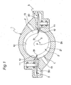
Fig. 1 is a cross-sectional view showing a first embodiment of the screw compressor according to the present invention; -
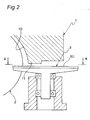
Fig. 2 is an enlarged sectional view of the screw compressor; -
Fig. 3 is a view taken along the line A-A ofFig. 2 ; -
Fig. 4 is a sectional view showing another embodiment of the seal surface; -
Fig. 5 is a plan view showing a second embodiment of the screw compressor according to the present invention; -
Fig. 6 is a side view showing a third embodiment of the screw compressor according to the present invention; -
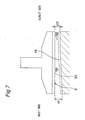
Fig. 7 is a side view showing a fourth embodiment of the screw compressor according to the present invention; -
Fig. 8 is an enlarged sectional view of a conventional screw compressor; and -
Fig. 9 is a view taken along the line B-B ofFig. 8 . - Hereinbelow, the present invention will be described in detail by way of embodiments thereof illustrated in the accompanying drawings.
-
Fig. 1 is a cross-sectional view showing a first embodiment of the screw compressor according to the invention. This screw compressor is a single screw compressor which includes: acasing 1 having acylinder 10; a cylindrical-shaped screw rotor 2 to be fitted to the cylinder 10'; and agate rotor 3 to be engaged with thescrew rotor 2. - The
screw rotor 2 has, on its outer peripheral surface, a plurality ofspiral groove portions 21. Thegate rotor 3, which is disc-shaped, has on its outer peripheral surface a plurality oftooth portions 31 in a gear form. Thegroove portions 21 of thescrew rotor 2 and thetooth portions 31 of thegate rotor 3 are to be engaged with each other. - Mutual engagement of the
screw rotor 2 and thegate rotor 3 causes a compression chamber C to be defined. That is, the compression chamber C is a space defined by thegroove portions 21 of thescrew rotor 2, thetooth portions 31 of thegate rotor 3 and an inner surface of thecylinder 10 of thecasing 1. - The
gate rotor 3 is placed in one pair on right and left of thescrew rotor 2 in point symmetry about anaxis 2a of thescrew rotor 2. Thecasing 1 is provided with a throughhole 12 running through thecylinder 10, and thegate rotor 3 intrudes through this throughhole 12 into thecylinder 10. - The
screw rotor 2 rotates about theaxis 2a in an arrow S direction. Along with this rotation of thescrew rotor 2, thegate rotor 3 rotates to compress the gas in the compression chamber C. Thescrew rotor 2 is rotated by a motor (not shown) housed in thecasing 1. - That is, a low-pressure gas is sucked into the compression chamber C from one end side of the
screw rotor 2 in theaxis 2a direction. After the low-pressure gas is compressed in the compression chamber C, the compressed high-pressure gas is discharged from anoutlet opening 13 provided on the other end side of thescrew rotor 2 in theaxis 2a direction. - As shown in
Fig. 2 , which is an enlarged sectional view, andFig. 3 , which is the line A-A view ofFig. 2 , aseal surface 11 of thecasing 1 is opposed to onesurface 30 of thegate rotor 3. - In
Fig. 3 , the left side of thescrew rotor 2 as viewed in the drawing sheet is assumed as an inlet side on which the gas is sucked into the compression chamber C, while the right side of thescrew rotor 2 in the drawing sheet is assumed as an outlet side on which the gas is discharged from the compression chamber C. - The
seal surface 11 of thecasing 1 is a surface which is to be set into adjacent connection with the inner surface of thecylinder 10. Theseal surface 11 of thecasing 1 extends in a direction parallel to theaxis 2a of thescrew rotor 2. - The one
surface 30 of thegate rotor 3 forms part of an inner surface of the compression chamber C. Between theseal surface 11 of thecasing 1 and the onesurface 30 of thegate rotor 3 is provided a gap of about 60 µm as an example. - With regard to the width of the
seal surface 11 of thecasing 1, a gas-outlet side width Wd of thescrew rotor 2 is larger than a gas-inlet side width Ws of thescrew rotor 2. - More specifically, a first edge 11a of the
seal surface 11 on itsscrew rotor 2 side is formed in a linear shape so as to be parallel to theaxis 2a of thescrew rotor 2. A second edge 11b of theseal surface 11 opposed to the first edge 11a is formed in a linear shape with such a skew as to be increasingly farther from the first edge 11a on the outlet side. That is, the width of theseal surface 11 increases gradually toward the outlet side. - According to the screw compressor constructed as described above, with regard to the width of the
seal surface 11 of thecasing 1, by the arrangement that the gas-outlet side width Wd of thescrew rotor 2 is larger than the gas-inlet side width Ws of thescrew rotor 2, although the gas pressure in the compression chamber C defined by mutual engagement of thescrew rotor 2 and thegate rotor 3 becomes higher on the gas outlet side of thescrew rotor 2, yet the outlet side width Wd of theseal surface 11 is so large that the gas within the compression chamber C can be prevented from leaking through between theseal surface 11 of thecasing 1 and the onesurface 30 of thegate rotor 3. - That is, the gas pressure in the compression chamber C is higher on the outlet side of the screw rotor 2 (Ps < Pd in
Fig. 3 ). However, because the outlet side width Wd of theseal surface 11 is larger than the inlet side width Ws of theseal surface 11, the pressure gradient (dP/dx = (Pd-Pg)/Wd) between theseal surface 11 and the onesurface 30 becomes smaller on the outlet side of thescrew rotor 2, so that on the outlet side of thescrew rotor 2, the gas in the compression chamber C can be prevented from leaking into the low-pressure space in which thegate rotor 3 is housed. In addition, the pressure Ps refers to a gas pressure on the inlet side in the compression chamber C, the pressure Pd refers to a gas pressure on the outlet side in the compression chamber C, and the pressure Pg refers to a pressure of the low-pressure space in which thegate rotor 3 is housed. - Also according to the screw compressor of the above construction, the inlet side width Ws of the
seal surface 11 may be small as it is, so that the area over which theseal surface 11 should have a flatness can be made smaller. Thus, contact of theseal surface 11 of thecasing 1 and the onesurface 30 of thegate rotor 3 with each other can be prevented. - In addition, it is also allowable that as shown in
Fig. 4 , afirst edge 16a of aseal surface 16 on itsscrew rotor 2 side (as seen inFig. 3 ) is formed in a linear shape so as to be parallel to theaxis 2a of thescrew rotor 2 while asecond edge 16b of theseal surface 16 opposed to thefirst edge 16a is formed in a concavely curved shape so as to be farther from thefirst edge 16a on the outlet side. -
Fig. 5 shows a second embodiment of the screw compressor according to the invention. This second embodiment differs from the first embodiment in the shape of the seal surface of the casing. In this second embodiment, like component members in conjunction with the first embodiment are designated by like reference signs and their detailed description is omitted. - As shown in
Fig. 5 , aseal surface 17 has afirst edge 17a on thescrew rotor 2 side and asecond edge 17b opposed to thefirst edge 17a. - The
first edge 17a is formed in a linear shape so as to be parallel to theaxis 2a of thescrew rotor 2. - The
second edge 17b has afirst portion 171 and asecond portion 172 in this order from gas inlet side toward outlet side of thescrew rotor 2. - The
first portion 171 is formed in a linear shape so as to be farther from thefirst edge 17a on the outlet side. In addition, thefirst portion 171 may be formed in a curved shape. - The
second portion 172 is formed in a linear shape so as to be parallel to thefirst edge 17a. - More specifically, a gas pressure in the compression chamber C defined by mutual engagement of the
screw rotor 2 and thegate rotor 3 is constant on the gas outlet side of thescrew rotor 2. Thesecond portion 172 is provided at a position corresponding to a constant-gas-pressure portion in the compression chamber C. - According to the screw compressor constructed as described above, the
first portion 171 is formed so as to be farther from thefirst edge 17a on the outlet side, while thesecond portion 172 is formed so as to be parallel to thefirst edge 17a. Therefore, the outlet side width of theseal surface 17 can be made smaller, so that the area over which theseal surface 17 should have a flatness can be made smaller, thus making it possible to prevent contact of theseal surface 17 of thecasing 1 and the onesurface 30 of thegate rotor 3 with each other. - Generally, the gas pressure in the compression chamber C defined by mutual engagement of the
screw rotor 2 and thegate rotor 3 is constant on the gas outlet side of thescrew rotor 2. Therefore, even when thesecond portion 172 on the outlet side is formed so as to be parallel to thefirst edge 17a, the gas in the compression chamber C can be prevented from leaking through between theseal surface 17 of thecasing 1 and the onesurface 30 of thegate rotor 3. - Further, since the
second portion 172 is provided at a position corresponding to a constant-gas-pressure portion in the compression chamber C, leaks of the gas in the compression chamber C can effectively be prevented. -
Fig. 6 shows a third embodiment of the screw compressor according to the invention. This third embodiment differs from the first embodiment in the shape of the seal surface of the casing. In this third embodiment, like component members in conjunction with the first embodiment are designated by like reference signs and their detailed description is omitted. - As shown in
Fig. 6 , with regard to the gap between the onesurface 30 of thegate rotor 3 and aseal surface 18, a gap H2 on the gas-outlet side of thescrew rotor 2 is smaller than a gap H1 on the gas-inlet side of the screw rotor. - The
seal surface 18 is formed so as to be increasingly closer to the onesurface 30 of thegate rotor 3 on the outlet side. - According to the screw compressor constructed as described above, with regard to the gap between the one
surface 30 of thegate rotor 3 and theseal surface 18, since the gas-outlet side gap. H2 of thescrew rotor 2 is smaller than the gas-inlet side gap H1 of thescrew rotor 2, the gas pressure in the compression chamber C defined by mutual engagement of thescrew rotor 2 and thegate rotor 3 becomes higher on the gas outlet side of thescrew rotor 2. However, the gap between the onesurface 30 of thegate rotor 3 and theseal surface 18 is so small that the gas in the compression chamber C can be prevented from leaking through between theseal surface 18 of thecasing 1 and the onesurface 30 of thegate rotor 3. - Further, the inlet side gap between the one
surface 30 of thegate rotor 3 and theseal surface 18 may be large as it is, under which condition contact between theseal surface 18 of thecasing 1 and the onesurface 30 of thegate rotor 3 can be prevented. -
Fig. 7 shows a fourth embodiment of the screw compressor according to the invention. This fourth embodiment differs from the first embodiment in the shape of the seal surface of the casing. In this fourth embodiment, like component members in conjunction with the third embodiment are designated by like reference signs and their detailed description is omitted. - As shown in
Fig. 7 , aseal surface 19 has a firstplanar portion 191 and a secondplanar portion 192 in this order from gas inlet side toward outlet side of thescrew rotor 2. - The first
planar portion 191 is formed so as to be increasingly closer to the onesurface 30 of thegate rotor 3 on the outlet side. - The second
planar portion 192 is formed so as to be parallel to the onesurface 30 of thegate rotor 3. - In addition, the gas pressure in the compression chamber C defined by mutual engagement of the
screw rotor 2 and thegate rotor 3 is constant on the gas outlet side of thescrew rotor 2. Therefore, the secondplanar portion 192 may be provided at a position corresponding to a constant-gas-pressure portion in the compression chamber C. - According to the screw compressor constructed as described above, the first
planar portion 191 is formed so as to be increasingly closer to the onesurface 30 of thegate rotor 3 on the outlet side, while the secondplanar portion 192 is formed so as to be parallel to the onesurface 30 of thegate rotor 3. Therefore, the outlet side gap between the onesurface 30 of thegate rotor 3 and theseal surface 19 can be made larger, so that contact between theseal surface 19 of thecasing 1 and the onesurface 30 of thegate rotor 3 can be prevented. - Generally, the gas pressure in the compression chamber C defined by mutual engagement of the
screw rotor 2 and thegate rotor 3 is constant on the gas outlet side of thescrew rotor 2. Therefore, even when the secondplanar portion 192 on the outlet side is formed so as to be parallel to the onesurface 30 of thegate rotor 3, the gas in the compression chamber C can be prevented from leaking through between theseal surface 19 of thecasing 1 and the onesurface 30 of thegate rotor 3. - It is noted that the present invention is not limited to the above-described embodiments. For example, the width of the seal surface of the casing may also be formed so as to increase stepwise toward the outlet side, and the seal surface may be formed into any shape only if the outlet side width of the seal surface is larger than the inlet side width of the seal surface.
- Furthermore, the gap between the one surface of the gate rotor and the seal surface may be formed so as to decrease stepwise toward the outlet side, and the seal surface may be formed into any shape only if the outlet side gap is smaller than the inlet side gap.
Claims (5)
- A screw compressor comprising:a casing (1) having a cylinder (10);a cylindrical-shaped screw rotor (2) to be fitted to the cylinder (10); anda gate rotor (3) to be engaged with the screw rotor (2), whereinwith regard to a width of a seal surface (11, 16, 17, 18, 19) of the casing (1) opposed to one surface (30) of the gate rotor (3), a width (Wd) on a gas-outlet side of the screw rotor (2) is larger than a width (Ws) on a gas-inlet side of the screw rotor (2).
- The screw compressor as claimed in Claim 1, wherein
the seal surface (17) has a first edge (17a) on a screw rotor (2) side and a second edge (17b) opposed to the first edge (17a),
the first edge (17a) is formed so as to be parallel to an axis (2a) of the screw rotor (2),
the second edge (17b) has a first portion (171) and a second portion (172) in this order from gas inlet side toward outlet side of the screw rotor (2), and
the first portion (171) is formed so as to be farther from the first edge (17a) on its outlet side, while
the second portion (172) is formed so as to be parallel to the first edge (17a). - The screw compressor as claimed in Claim 2, wherein
a gas pressure in a compression chamber (C) defined by mutual engagement of the screw rotor (2) and the gate rotor (3) is constant on a gas outlet side of the screw rotor (2), and
the second portion (172) is provided at a position corresponding to a constant-gas-pressure portion in the compression chamber (C). - The screw compressor as claimed in any one of Claims 1 to 3, wherein
with regard to a gap between the one surface (30) of the gate rotor (3) and the seal surface (18, 19), a gap (H2) on the gas-outlet side of the screw rotor (2) is smaller than a gap (H1) on the gas-inlet side of the screw rotor (2). - The screw compressor as claimed in Claim 4, wherein
the seal surface (19) has a first planar portion (191) and a second planar portion (192) in this order from gas inlet side toward outlet side of the screw rotor (2), and
the first planar portion (191) is formed so as to be increasingly closer to the one surface (30) of the gate rotor (3) on the outlet side, while
the second planar portion (192) is formed so as to be parallel to the one surface (30) of the gate rotor (3).
Applications Claiming Priority (3)
| Application Number | Priority Date | Filing Date | Title |
|---|---|---|---|
| JP2007136079 | 2007-05-23 | ||
| JP2008111337A JP4211871B2 (en) | 2007-05-23 | 2008-04-22 | Screw compressor |
| PCT/JP2008/058490 WO2008142994A1 (en) | 2007-05-23 | 2008-05-07 | Screw compressor |
Publications (3)
| Publication Number | Publication Date |
|---|---|
| EP2148093A1 true EP2148093A1 (en) | 2010-01-27 |
| EP2148093A4 EP2148093A4 (en) | 2015-01-21 |
| EP2148093B1 EP2148093B1 (en) | 2018-07-11 |
Family
ID=40031709
Family Applications (1)
| Application Number | Title | Priority Date | Filing Date |
|---|---|---|---|
| EP08752382.5A Not-in-force EP2148093B1 (en) | 2007-05-23 | 2008-05-07 | Screw compressor |
Country Status (6)
| Country | Link |
|---|---|
| US (1) | US8419397B2 (en) |
| EP (1) | EP2148093B1 (en) |
| JP (1) | JP4211871B2 (en) |
| CN (1) | CN101668951B (en) |
| ES (1) | ES2681194T3 (en) |
| WO (1) | WO2008142994A1 (en) |
Families Citing this family (3)
| Publication number | Priority date | Publication date | Assignee | Title |
|---|---|---|---|---|
| JP4412417B2 (en) * | 2007-12-07 | 2010-02-10 | ダイキン工業株式会社 | Single screw compressor |
| JP4400689B2 (en) * | 2007-12-28 | 2010-01-20 | ダイキン工業株式会社 | Screw compressor |
| US9057373B2 (en) | 2011-11-22 | 2015-06-16 | Vilter Manufacturing Llc | Single screw compressor with high output |
Family Cites Families (14)
| Publication number | Priority date | Publication date | Assignee | Title |
|---|---|---|---|---|
| US3133695A (en) * | 1960-06-22 | 1964-05-19 | Zimmern Fernand | Compressors |
| US3133694A (en) * | 1962-01-31 | 1964-05-19 | Borsig Ag | Rotary piston engine |
| FR1331998A (en) * | 1962-05-08 | 1963-07-12 | Improvements to rotary screw compressors and liquid seals | |
| FR2148677A5 (en) * | 1971-07-30 | 1973-03-23 | Zimmern Bernard | |
| FR2541367B1 (en) * | 1982-01-14 | 1986-01-03 | Zimmern Bernard | SEALING RING FOR VOLUMETRIC MACHINE WITH SCREWS AND PINION |
| FR2519712A1 (en) * | 1982-01-14 | 1983-07-18 | Omphale Sa | CYLINDRO-CONICAL SCREW FOR SCREW AND SCREW VOLUMETRIC MACHINE |
| JPH0533740Y2 (en) * | 1988-03-28 | 1993-08-26 | ||
| JPH07111184B2 (en) * | 1988-12-05 | 1995-11-29 | 株式会社荏原製作所 | Screw compressor |
| US5087182A (en) * | 1989-09-12 | 1992-02-11 | Bernard Zimmern | Casing construction for screw compression/expansion machines |
| US5080568A (en) * | 1990-09-20 | 1992-01-14 | Bernard Zimmern | Positive displacement rotary machine |
| JP3170882B2 (en) * | 1992-07-24 | 2001-05-28 | ダイキン工業株式会社 | Single screw compressor |
| JP3731399B2 (en) | 1999-08-30 | 2006-01-05 | ダイキン工業株式会社 | Screw compressor |
| CN1079501C (en) * | 1999-10-26 | 2002-02-20 | 查世樑 | Energy-saving single-bolt compressor |
| US7153112B2 (en) * | 2003-12-09 | 2006-12-26 | Dresser-Rand Company | Compressor and a method for compressing fluid |
-
2008
- 2008-04-22 JP JP2008111337A patent/JP4211871B2/en not_active Expired - Fee Related
- 2008-05-07 US US12/601,117 patent/US8419397B2/en not_active Expired - Fee Related
- 2008-05-07 EP EP08752382.5A patent/EP2148093B1/en not_active Not-in-force
- 2008-05-07 CN CN2008800139746A patent/CN101668951B/en not_active Expired - Fee Related
- 2008-05-07 WO PCT/JP2008/058490 patent/WO2008142994A1/en not_active Ceased
- 2008-05-07 ES ES08752382.5T patent/ES2681194T3/en active Active
Also Published As
| Publication number | Publication date |
|---|---|
| CN101668951B (en) | 2011-06-08 |
| ES2681194T3 (en) | 2018-09-12 |
| US8419397B2 (en) | 2013-04-16 |
| JP2009002326A (en) | 2009-01-08 |
| US20100158737A1 (en) | 2010-06-24 |
| CN101668951A (en) | 2010-03-10 |
| EP2148093A4 (en) | 2015-01-21 |
| JP4211871B2 (en) | 2009-01-21 |
| EP2148093B1 (en) | 2018-07-11 |
| WO2008142994A1 (en) | 2008-11-27 |
Similar Documents
| Publication | Publication Date | Title |
|---|---|---|
| JP5183938B2 (en) | Sealing device | |
| US9366253B2 (en) | Scroll compressor and processing method of scroll including a projection on a tip seal and a hole in a tip seal groove | |
| US20190162185A1 (en) | Scroll compressor | |
| US9702361B2 (en) | Claw pump with relief space | |
| EP2148093B1 (en) | Screw compressor | |
| EP2236834A1 (en) | Single screw compressor | |
| US8402649B2 (en) | Scroll member, method of manufacturing same, compression mechanism and scroll compressor | |
| EP1826406B1 (en) | Compressor | |
| US20200378386A1 (en) | Rotary compressor | |
| US20190264688A1 (en) | Scroll compressor | |
| KR102949914B1 (en) | Scroll compressor | |
| JP2011236823A (en) | Screw compressor | |
| US11428223B2 (en) | Rotary compressor with wear avoiding portion | |
| EP2236833A1 (en) | Screw compressor | |
| US7556485B2 (en) | Rotary compressor with reduced refrigeration gas leaks during compression while preventing seizure | |
| KR20240033272A (en) | Elements, devices and methods for compressing gases | |
| JP2006307760A (en) | Scroll type fluid machine | |
| JP4461016B2 (en) | Helical screw rotor compressor | |
| US11519406B2 (en) | Oil pump having housing with seal portion | |
| EP2441959B1 (en) | Scroll compressor | |
| EP2857688B1 (en) | Rotary compressor | |
| US20150337837A1 (en) | Scroll member, method of manufacturing same, compression mechanism and scroll compressor | |
| JP2008291681A (en) | Screw compressor | |
| CN119616863A (en) | Pump structure, compressor, air conditioner | |
| JP2008240709A (en) | Compressor |
Legal Events
| Date | Code | Title | Description |
|---|---|---|---|
| PUAI | Public reference made under article 153(3) epc to a published international application that has entered the european phase |
Free format text: ORIGINAL CODE: 0009012 |
|
| 17P | Request for examination filed |
Effective date: 20091021 |
|
| AK | Designated contracting states |
Kind code of ref document: A1 Designated state(s): AT BE BG CH CY CZ DE DK EE ES FI FR GB GR HR HU IE IS IT LI LT LU LV MC MT NL NO PL PT RO SE SI SK TR |
|
| AX | Request for extension of the european patent |
Extension state: AL BA MK RS |
|
| DAX | Request for extension of the european patent (deleted) | ||
| A4 | Supplementary search report drawn up and despatched |
Effective date: 20141223 |
|
| RIC1 | Information provided on ipc code assigned before grant |
Ipc: F04C 18/52 20060101AFI20141217BHEP |
|
| STAA | Information on the status of an ep patent application or granted ep patent |
Free format text: STATUS: EXAMINATION IS IN PROGRESS |
|
| 17Q | First examination report despatched |
Effective date: 20170728 |
|
| GRAP | Despatch of communication of intention to grant a patent |
Free format text: ORIGINAL CODE: EPIDOSNIGR1 |
|
| STAA | Information on the status of an ep patent application or granted ep patent |
Free format text: STATUS: GRANT OF PATENT IS INTENDED |
|
| INTG | Intention to grant announced |
Effective date: 20180208 |
|
| GRAJ | Information related to disapproval of communication of intention to grant by the applicant or resumption of examination proceedings by the epo deleted |
Free format text: ORIGINAL CODE: EPIDOSDIGR1 |
|
| STAA | Information on the status of an ep patent application or granted ep patent |
Free format text: STATUS: EXAMINATION IS IN PROGRESS |
|
| INTC | Intention to grant announced (deleted) | ||
| GRAJ | Information related to disapproval of communication of intention to grant by the applicant or resumption of examination proceedings by the epo deleted |
Free format text: ORIGINAL CODE: EPIDOSDIGR1 |
|
| STAA | Information on the status of an ep patent application or granted ep patent |
Free format text: STATUS: GRANT OF PATENT IS INTENDED |
|
| GRAS | Grant fee paid |
Free format text: ORIGINAL CODE: EPIDOSNIGR3 |
|
| GRAP | Despatch of communication of intention to grant a patent |
Free format text: ORIGINAL CODE: EPIDOSNIGR1 |
|
| GRAA | (expected) grant |
Free format text: ORIGINAL CODE: 0009210 |
|
| STAA | Information on the status of an ep patent application or granted ep patent |
Free format text: STATUS: THE PATENT HAS BEEN GRANTED |
|
| INTG | Intention to grant announced |
Effective date: 20180605 |
|
| AK | Designated contracting states |
Kind code of ref document: B1 Designated state(s): AT BE BG CH CY CZ DE DK EE ES FI FR GB GR HR HU IE IS IT LI LT LU LV MC MT NL NO PL PT RO SE SI SK TR |
|
| REG | Reference to a national code |
Ref country code: GB Ref legal event code: FG4D |
|
| REG | Reference to a national code |
Ref country code: CH Ref legal event code: EP |
|
| REG | Reference to a national code |
Ref country code: AT Ref legal event code: REF Ref document number: 1017161 Country of ref document: AT Kind code of ref document: T Effective date: 20180715 |
|
| REG | Reference to a national code |
Ref country code: DE Ref legal event code: R096 Ref document number: 602008055951 Country of ref document: DE |
|
| REG | Reference to a national code |
Ref country code: IE Ref legal event code: FG4D |
|
| REG | Reference to a national code |
Ref country code: ES Ref legal event code: FG2A Ref document number: 2681194 Country of ref document: ES Kind code of ref document: T3 Effective date: 20180912 |
|
| REG | Reference to a national code |
Ref country code: NL Ref legal event code: MP Effective date: 20180711 |
|
| REG | Reference to a national code |
Ref country code: LT Ref legal event code: MG4D |
|
| REG | Reference to a national code |
Ref country code: AT Ref legal event code: MK05 Ref document number: 1017161 Country of ref document: AT Kind code of ref document: T Effective date: 20180711 |
|
| PG25 | Lapsed in a contracting state [announced via postgrant information from national office to epo] |
Ref country code: NL Free format text: LAPSE BECAUSE OF FAILURE TO SUBMIT A TRANSLATION OF THE DESCRIPTION OR TO PAY THE FEE WITHIN THE PRESCRIBED TIME-LIMIT Effective date: 20180711 |
|
| PG25 | Lapsed in a contracting state [announced via postgrant information from national office to epo] |
Ref country code: BG Free format text: LAPSE BECAUSE OF FAILURE TO SUBMIT A TRANSLATION OF THE DESCRIPTION OR TO PAY THE FEE WITHIN THE PRESCRIBED TIME-LIMIT Effective date: 20181011 Ref country code: LT Free format text: LAPSE BECAUSE OF FAILURE TO SUBMIT A TRANSLATION OF THE DESCRIPTION OR TO PAY THE FEE WITHIN THE PRESCRIBED TIME-LIMIT Effective date: 20180711 Ref country code: IS Free format text: LAPSE BECAUSE OF FAILURE TO SUBMIT A TRANSLATION OF THE DESCRIPTION OR TO PAY THE FEE WITHIN THE PRESCRIBED TIME-LIMIT Effective date: 20181111 Ref country code: SE Free format text: LAPSE BECAUSE OF FAILURE TO SUBMIT A TRANSLATION OF THE DESCRIPTION OR TO PAY THE FEE WITHIN THE PRESCRIBED TIME-LIMIT Effective date: 20180711 Ref country code: PL Free format text: LAPSE BECAUSE OF FAILURE TO SUBMIT A TRANSLATION OF THE DESCRIPTION OR TO PAY THE FEE WITHIN THE PRESCRIBED TIME-LIMIT Effective date: 20180711 Ref country code: AT Free format text: LAPSE BECAUSE OF FAILURE TO SUBMIT A TRANSLATION OF THE DESCRIPTION OR TO PAY THE FEE WITHIN THE PRESCRIBED TIME-LIMIT Effective date: 20180711 Ref country code: NO Free format text: LAPSE BECAUSE OF FAILURE TO SUBMIT A TRANSLATION OF THE DESCRIPTION OR TO PAY THE FEE WITHIN THE PRESCRIBED TIME-LIMIT Effective date: 20181011 Ref country code: GR Free format text: LAPSE BECAUSE OF FAILURE TO SUBMIT A TRANSLATION OF THE DESCRIPTION OR TO PAY THE FEE WITHIN THE PRESCRIBED TIME-LIMIT Effective date: 20181012 Ref country code: FI Free format text: LAPSE BECAUSE OF FAILURE TO SUBMIT A TRANSLATION OF THE DESCRIPTION OR TO PAY THE FEE WITHIN THE PRESCRIBED TIME-LIMIT Effective date: 20180711 |
|
| PG25 | Lapsed in a contracting state [announced via postgrant information from national office to epo] |
Ref country code: HR Free format text: LAPSE BECAUSE OF FAILURE TO SUBMIT A TRANSLATION OF THE DESCRIPTION OR TO PAY THE FEE WITHIN THE PRESCRIBED TIME-LIMIT Effective date: 20180711 Ref country code: LV Free format text: LAPSE BECAUSE OF FAILURE TO SUBMIT A TRANSLATION OF THE DESCRIPTION OR TO PAY THE FEE WITHIN THE PRESCRIBED TIME-LIMIT Effective date: 20180711 |
|
| REG | Reference to a national code |
Ref country code: DE Ref legal event code: R097 Ref document number: 602008055951 Country of ref document: DE |
|
| PG25 | Lapsed in a contracting state [announced via postgrant information from national office to epo] |
Ref country code: EE Free format text: LAPSE BECAUSE OF FAILURE TO SUBMIT A TRANSLATION OF THE DESCRIPTION OR TO PAY THE FEE WITHIN THE PRESCRIBED TIME-LIMIT Effective date: 20180711 Ref country code: RO Free format text: LAPSE BECAUSE OF FAILURE TO SUBMIT A TRANSLATION OF THE DESCRIPTION OR TO PAY THE FEE WITHIN THE PRESCRIBED TIME-LIMIT Effective date: 20180711 Ref country code: CZ Free format text: LAPSE BECAUSE OF FAILURE TO SUBMIT A TRANSLATION OF THE DESCRIPTION OR TO PAY THE FEE WITHIN THE PRESCRIBED TIME-LIMIT Effective date: 20180711 |
|
| PLBE | No opposition filed within time limit |
Free format text: ORIGINAL CODE: 0009261 |
|
| STAA | Information on the status of an ep patent application or granted ep patent |
Free format text: STATUS: NO OPPOSITION FILED WITHIN TIME LIMIT |
|
| PG25 | Lapsed in a contracting state [announced via postgrant information from national office to epo] |
Ref country code: SK Free format text: LAPSE BECAUSE OF FAILURE TO SUBMIT A TRANSLATION OF THE DESCRIPTION OR TO PAY THE FEE WITHIN THE PRESCRIBED TIME-LIMIT Effective date: 20180711 Ref country code: DK Free format text: LAPSE BECAUSE OF FAILURE TO SUBMIT A TRANSLATION OF THE DESCRIPTION OR TO PAY THE FEE WITHIN THE PRESCRIBED TIME-LIMIT Effective date: 20180711 |
|
| 26N | No opposition filed |
Effective date: 20190412 |
|
| PG25 | Lapsed in a contracting state [announced via postgrant information from national office to epo] |
Ref country code: SI Free format text: LAPSE BECAUSE OF FAILURE TO SUBMIT A TRANSLATION OF THE DESCRIPTION OR TO PAY THE FEE WITHIN THE PRESCRIBED TIME-LIMIT Effective date: 20180711 |
|
| REG | Reference to a national code |
Ref country code: CH Ref legal event code: PL |
|
| GBPC | Gb: european patent ceased through non-payment of renewal fee |
Effective date: 20190507 |
|
| PG25 | Lapsed in a contracting state [announced via postgrant information from national office to epo] |
Ref country code: LI Free format text: LAPSE BECAUSE OF NON-PAYMENT OF DUE FEES Effective date: 20190531 Ref country code: MC Free format text: LAPSE BECAUSE OF FAILURE TO SUBMIT A TRANSLATION OF THE DESCRIPTION OR TO PAY THE FEE WITHIN THE PRESCRIBED TIME-LIMIT Effective date: 20180711 Ref country code: CH Free format text: LAPSE BECAUSE OF NON-PAYMENT OF DUE FEES Effective date: 20190531 |
|
| REG | Reference to a national code |
Ref country code: BE Ref legal event code: MM Effective date: 20190531 |
|
| PG25 | Lapsed in a contracting state [announced via postgrant information from national office to epo] |
Ref country code: LU Free format text: LAPSE BECAUSE OF NON-PAYMENT OF DUE FEES Effective date: 20190507 |
|
| PG25 | Lapsed in a contracting state [announced via postgrant information from national office to epo] |
Ref country code: TR Free format text: LAPSE BECAUSE OF FAILURE TO SUBMIT A TRANSLATION OF THE DESCRIPTION OR TO PAY THE FEE WITHIN THE PRESCRIBED TIME-LIMIT Effective date: 20180711 |
|
| PG25 | Lapsed in a contracting state [announced via postgrant information from national office to epo] |
Ref country code: IT Free format text: LAPSE BECAUSE OF NON-PAYMENT OF DUE FEES Effective date: 20190507 Ref country code: IE Free format text: LAPSE BECAUSE OF NON-PAYMENT OF DUE FEES Effective date: 20190507 Ref country code: GB Free format text: LAPSE BECAUSE OF NON-PAYMENT OF DUE FEES Effective date: 20190507 |
|
| PG25 | Lapsed in a contracting state [announced via postgrant information from national office to epo] |
Ref country code: BE Free format text: LAPSE BECAUSE OF NON-PAYMENT OF DUE FEES Effective date: 20190531 |
|
| PG25 | Lapsed in a contracting state [announced via postgrant information from national office to epo] |
Ref country code: FR Free format text: LAPSE BECAUSE OF NON-PAYMENT OF DUE FEES Effective date: 20190531 Ref country code: PT Free format text: LAPSE BECAUSE OF FAILURE TO SUBMIT A TRANSLATION OF THE DESCRIPTION OR TO PAY THE FEE WITHIN THE PRESCRIBED TIME-LIMIT Effective date: 20181111 |
|
| REG | Reference to a national code |
Ref country code: ES Ref legal event code: FD2A Effective date: 20200925 |
|
| PG25 | Lapsed in a contracting state [announced via postgrant information from national office to epo] |
Ref country code: ES Free format text: LAPSE BECAUSE OF NON-PAYMENT OF DUE FEES Effective date: 20190508 |
|
| PG25 | Lapsed in a contracting state [announced via postgrant information from national office to epo] |
Ref country code: CY Free format text: LAPSE BECAUSE OF FAILURE TO SUBMIT A TRANSLATION OF THE DESCRIPTION OR TO PAY THE FEE WITHIN THE PRESCRIBED TIME-LIMIT Effective date: 20180711 |
|
| PG25 | Lapsed in a contracting state [announced via postgrant information from national office to epo] |
Ref country code: HU Free format text: LAPSE BECAUSE OF FAILURE TO SUBMIT A TRANSLATION OF THE DESCRIPTION OR TO PAY THE FEE WITHIN THE PRESCRIBED TIME-LIMIT; INVALID AB INITIO Effective date: 20080507 Ref country code: MT Free format text: LAPSE BECAUSE OF FAILURE TO SUBMIT A TRANSLATION OF THE DESCRIPTION OR TO PAY THE FEE WITHIN THE PRESCRIBED TIME-LIMIT Effective date: 20180711 |
|
| PGFP | Annual fee paid to national office [announced via postgrant information from national office to epo] |
Ref country code: DE Payment date: 20210413 Year of fee payment: 14 |
|
| REG | Reference to a national code |
Ref country code: DE Ref legal event code: R119 Ref document number: 602008055951 Country of ref document: DE |
|
| PG25 | Lapsed in a contracting state [announced via postgrant information from national office to epo] |
Ref country code: DE Free format text: LAPSE BECAUSE OF NON-PAYMENT OF DUE FEES Effective date: 20221201 |