EP2148025A2 - Door handle apparatus - Google Patents
Door handle apparatus Download PDFInfo
- Publication number
- EP2148025A2 EP2148025A2 EP20090166178 EP09166178A EP2148025A2 EP 2148025 A2 EP2148025 A2 EP 2148025A2 EP 20090166178 EP20090166178 EP 20090166178 EP 09166178 A EP09166178 A EP 09166178A EP 2148025 A2 EP2148025 A2 EP 2148025A2
- Authority
- EP
- European Patent Office
- Prior art keywords
- lock detection
- detection electrode
- outer panel
- electrode
- door handle
- Prior art date
- Legal status (The legal status is an assumption and is not a legal conclusion. Google has not performed a legal analysis and makes no representation as to the accuracy of the status listed.)
- Granted
Links
- 238000001514 detection method Methods 0.000 claims abstract description 162
- 230000008878 coupling Effects 0.000 claims abstract description 27
- 238000010168 coupling process Methods 0.000 claims abstract description 27
- 238000005859 coupling reaction Methods 0.000 claims abstract description 27
- 239000002184 metal Substances 0.000 claims description 4
- XLYOFNOQVPJJNP-UHFFFAOYSA-N water Substances O XLYOFNOQVPJJNP-UHFFFAOYSA-N 0.000 description 32
- 238000013459 approach Methods 0.000 description 8
- 239000000758 substrate Substances 0.000 description 8
- 230000007257 malfunction Effects 0.000 description 6
- 230000000694 effects Effects 0.000 description 4
- 101100489713 Saccharomyces cerevisiae (strain ATCC 204508 / S288c) GND1 gene Proteins 0.000 description 2
- 238000010586 diagram Methods 0.000 description 2
- 101100489717 Saccharomyces cerevisiae (strain ATCC 204508 / S288c) GND2 gene Proteins 0.000 description 1
- 230000004308 accommodation Effects 0.000 description 1
- 230000005540 biological transmission Effects 0.000 description 1
- 238000004891 communication Methods 0.000 description 1
- 230000003247 decreasing effect Effects 0.000 description 1
- 230000005611 electricity Effects 0.000 description 1
- 238000012856 packing Methods 0.000 description 1
- 239000011347 resin Substances 0.000 description 1
- 229920005989 resin Polymers 0.000 description 1
- 239000003566 sealing material Substances 0.000 description 1
- 238000005406 washing Methods 0.000 description 1
Images




Classifications
-
- E—FIXED CONSTRUCTIONS
- E05—LOCKS; KEYS; WINDOW OR DOOR FITTINGS; SAFES
- E05B—LOCKS; ACCESSORIES THEREFOR; HANDCUFFS
- E05B81/00—Power-actuated vehicle locks
- E05B81/54—Electrical circuits
- E05B81/64—Monitoring or sensing, e.g. by using switches or sensors
- E05B81/76—Detection of handle operation; Detection of a user approaching a handle; Electrical switching actions performed by door handles
- E05B81/78—Detection of handle operation; Detection of a user approaching a handle; Electrical switching actions performed by door handles as part of a hands-free locking or unlocking operation
-
- E—FIXED CONSTRUCTIONS
- E05—LOCKS; KEYS; WINDOW OR DOOR FITTINGS; SAFES
- E05B—LOCKS; ACCESSORIES THEREFOR; HANDCUFFS
- E05B77/00—Vehicle locks characterised by special functions or purposes
- E05B77/34—Protection against weather or dirt, e.g. against water ingress
-
- E—FIXED CONSTRUCTIONS
- E05—LOCKS; KEYS; WINDOW OR DOOR FITTINGS; SAFES
- E05B—LOCKS; ACCESSORIES THEREFOR; HANDCUFFS
- E05B85/00—Details of vehicle locks not provided for in groups E05B77/00 - E05B83/00
- E05B85/10—Handles
- E05B85/14—Handles pivoted about an axis parallel to the wing
- E05B85/16—Handles pivoted about an axis parallel to the wing a longitudinal grip part being pivoted at one end about an axis perpendicular to the longitudinal axis of the grip part
-
- E—FIXED CONSTRUCTIONS
- E05—LOCKS; KEYS; WINDOW OR DOOR FITTINGS; SAFES
- E05B—LOCKS; ACCESSORIES THEREFOR; HANDCUFFS
- E05B81/00—Power-actuated vehicle locks
- E05B81/54—Electrical circuits
- E05B81/64—Monitoring or sensing, e.g. by using switches or sensors
- E05B81/76—Detection of handle operation; Detection of a user approaching a handle; Electrical switching actions performed by door handles
- E05B81/77—Detection of handle operation; Detection of a user approaching a handle; Electrical switching actions performed by door handles comprising sensors detecting the presence of the hand of a user
-
- Y—GENERAL TAGGING OF NEW TECHNOLOGICAL DEVELOPMENTS; GENERAL TAGGING OF CROSS-SECTIONAL TECHNOLOGIES SPANNING OVER SEVERAL SECTIONS OF THE IPC; TECHNICAL SUBJECTS COVERED BY FORMER USPC CROSS-REFERENCE ART COLLECTIONS [XRACs] AND DIGESTS
- Y10—TECHNICAL SUBJECTS COVERED BY FORMER USPC
- Y10T—TECHNICAL SUBJECTS COVERED BY FORMER US CLASSIFICATION
- Y10T292/00—Closure fasteners
- Y10T292/03—Miscellaneous
-
- Y—GENERAL TAGGING OF NEW TECHNOLOGICAL DEVELOPMENTS; GENERAL TAGGING OF CROSS-SECTIONAL TECHNOLOGIES SPANNING OVER SEVERAL SECTIONS OF THE IPC; TECHNICAL SUBJECTS COVERED BY FORMER USPC CROSS-REFERENCE ART COLLECTIONS [XRACs] AND DIGESTS
- Y10—TECHNICAL SUBJECTS COVERED BY FORMER USPC
- Y10T—TECHNICAL SUBJECTS COVERED BY FORMER US CLASSIFICATION
- Y10T292/00—Closure fasteners
- Y10T292/08—Bolts
- Y10T292/096—Sliding
- Y10T292/0969—Spring projected
- Y10T292/097—Operating means
- Y10T292/0994—Lever
-
- Y—GENERAL TAGGING OF NEW TECHNOLOGICAL DEVELOPMENTS; GENERAL TAGGING OF CROSS-SECTIONAL TECHNOLOGIES SPANNING OVER SEVERAL SECTIONS OF THE IPC; TECHNICAL SUBJECTS COVERED BY FORMER USPC CROSS-REFERENCE ART COLLECTIONS [XRACs] AND DIGESTS
- Y10—TECHNICAL SUBJECTS COVERED BY FORMER USPC
- Y10T—TECHNICAL SUBJECTS COVERED BY FORMER US CLASSIFICATION
- Y10T292/00—Closure fasteners
- Y10T292/08—Bolts
- Y10T292/096—Sliding
- Y10T292/1014—Operating means
-
- Y—GENERAL TAGGING OF NEW TECHNOLOGICAL DEVELOPMENTS; GENERAL TAGGING OF CROSS-SECTIONAL TECHNOLOGIES SPANNING OVER SEVERAL SECTIONS OF THE IPC; TECHNICAL SUBJECTS COVERED BY FORMER USPC CROSS-REFERENCE ART COLLECTIONS [XRACs] AND DIGESTS
- Y10—TECHNICAL SUBJECTS COVERED BY FORMER USPC
- Y10T—TECHNICAL SUBJECTS COVERED BY FORMER US CLASSIFICATION
- Y10T292/00—Closure fasteners
- Y10T292/57—Operators with knobs or handles
Definitions
- the present invention relates to a door handle apparatus having a function of detecting a command for locking a vehicle door and the like.
- a door handle apparatus on which a Smart Entry System (trademark) is mounted, is known, in which, for example, it is recognized that a user approaches a vehicle or that the user gets out of the vehicle, on the basis of a communication between a portable device, carried by the user, and a transmission device of the vehicle, while it is detected that a door lock command or a door unlock command is inputted by the user relative to a vehicle door in order to automatically execute locking and unlocking operations.
- Such door handle apparatus is disclosed in JP3502848A .
- an unlock sensor S ULK for detecting an unlock command of a user is arranged at a holding portion 110, at which a hand of the user may be inserted between an outer panel 200 of a vehicle door and a door handle 100.
- a lock sensor S LK for detecting a lock command of the user is arranged at an operational-portion extending portion 120, the operational-portion extending portion 120 being arranged at the door handle 100 to be adjacent to the holding portion 110 and extending from a portion for operating an opening and closing mechanism of the vehicle door.
- the lock sensor S LK and the unlock sensor S ULK are electrostatic capacitance sensors, which detect a fluctuation of the electrostatic capacitance.
- the lock sensor S LK and the unlock sensor S ULK detect the fluctuation of the electrostatic capacitance, which is generated when the hand of the user approaches a vicinity of each detection electrode of the lock sensor S LK and the unlock sensor S ULK , and thereby determining that the lock command or the unlock command are inputted.
- a value of electrostatic capacity C PANEL which is established between the outer panel 200 of the vehicle door and the detection electrode of the lock sensor S LK , is set as a standard value, and when a value of electrostatic capacity detected by the lock sensor S LK does not fluctuate for a great extent from the value of electrostatic capacity C PANEL , it is determined that the unlock command is not inputted.
- another electrostatic capacity C T is established between the detection electrode and the hand of the user so as to be in parallel with the electrostatic capacity C PANEL (i.e., C PANEL + C T ).
- the lock sensor S LK when the value of the electrostatic capacity, detected by the lock sensor S LK , is increased by a level corresponding to the value of electrostatic capacity C T , it is determined that the lock command is inputted.
- the detection principle may be applied to the unlock sensor S ULK .
- the lock sensor S LK and the unlock sensor S ULK are arranged at different portions of the door handle 100. Therefore, the lock command and the unlock command are detected in response to an operation of the user who touches the different portions of the door handle 100.
- a lock detection electrode (the lock sensor S LK ) is arranged at an end portion of an outer surface of the holding portion 110 (i.e., a surface of the holding portion 110 opposite from the outer panel 200). Therefore, when the user inserts his/her hand between the holding portion 110 and the outer panel 200 in order to unlock the vehicle door, and then pulls the door handle 100 in order to open the vehicle door, the user may accidentally touch a detection area of the lock sensor S LK with his/her hand. In such a case, both of the unlock command of the unlock sensor S LK and the lock command of the lock sensor S LK may be outputted simultaneously, and an appropriate command may not be inputted. Further, the user may touch the detection area of the lock sensor S LK with his/her hand when the vehicle door is opened, and thereby a locking operation may be unintentionally executed. Thus, an operation, which is not intended by the user, may be executed.
- a door handle apparatus for a vehicle includes a door handle including a first handle case having a holding portion for holding the door handle, the holding portion arranged to be distant from an outer surface of an outer panel of a vehicle door by a clearance, a second handle case serving as an outer portion of the door handle and arranged to cover the first handle case, a rotational-portion extending portion provided in the vicinity of one end portion of the door handle in a longitudinal direction of the door handle and extending so as to penetrate through the outer panel from the rotational portion rotatably supported by a supporting member arranged at an inner side of the outer panel, a operational-portion extending portion provided in the vicinity of the other end portion of the door handle in the longitudinal direction of the door handle and extending so as to penetrate through the outer panel from the operational portion operating an opening and closing mechanism of the vehicle door, and a lock detection electrode of an electrostatic capacity sensor, the lock detection electrode being arranged to face an inner surface of the second handle case facing the outer panel, the electrostatic capacity sensor detecting that
- the lock detection electrode includes an upper lock detection electrode and a lower lock detection electrode arranged to face an inner surface of an upper wall of the second handle case facing the outer panel and an inner surface of a lower wall of the second handle case facing the outer panel, respectively.
- a first electrode end surface of the upper lock detection electrode and a second electrode end surface of the lower lock detection electrode, each of which faces the outer panel, are formed into different shapes from each other, so that a level of capacitive coupling established between the lower lock detection electrode and the outer panel is set to be smaller than a level of capacitive coupling established between the upper lock detection electrode and the outer panel.
- the lock detection electrode (the upper lock detection electrode and the lower lock detection electrode) is arranged at the inner surfaces of the upper and lower walls of the second handle case. Therefore, a command for locking the vehicle door may not be inputted in response to the holding operation of the door handle by a user. More specifically, when the user holds the upper and lower walls of the second handle case between his/her fingers in order to input the command for locking the vehicle door, the command for locking the vehicle door is detected because dimension of the detection area of the upper and lower lock detection electrodes is sufficiently obtained. Further, because water drop flows from upper to the lower portions of the door handle, the water drop may easily accumulates at the lower portion of the door handle.
- the upper and lower lock detection electrodes are formed into the different shapes from each other, so that the capacitive coupling established between the second electrode end surface and the outer panel is smaller than the capacitive coupling established between the first electrode end surface and the outer panel. Therefore the water drop is less likely to form the bridge between the outer panel and the second electrode end surface, compared to the first electrode end surface. Accordingly, the sufficient clearance is provided for allowing the fluctuation of the electric permittivity at a shortest facing portion between the outer panel and the lower lock detection electrode and the fluctuation of the electrostatic capacity, which may be caused when the water drop approaches (i.e., comes in contact with) the lower lock detection electrode. Thus, the water drop is less likely to form the bridge between the outer panel and the second electrode end surface, at the lower lock detection electrode, which may be affected by the water drop. Accordingly, the electrostatic capacity sensor may not malfunction due to the water drop.
- the second electrode end surface of the lower lock detection electrode is formed so that a distance between the second electrode end surface of the lower lock detection electrode and the outer panel is set to be greater than a distance between the first electrode end surface of the upper lock detection electrode and the outer panel.
- the capacitive coupling established between the second electrode end surface of the lower lock detection electrode and the outer panel is set to be relatively smaller than the capacitive coupling established between the first electrode end surface of the upper lock detection electrode.
- the second electrode end surface of the lower lock detection electrode is formed so that a dimension of the second electrode end surface of the lower lock detection electrode is set to be smaller than a dimension of the first electrode end surface of the upper lock detection electrode.
- the capacitive coupling established between the second electrode end surface of the lower lock detection electrode and the outer panel is set to be relatively smaller than the capacitive coupling established between the first electrode end surface 36c of the upper lock detection electrode.
- the upper wall and the lower wall of the second handle case are formed to be asymmetrical to each other relative to a middle line m, extending from the rotational-portion extending portion to the operational-portion extending portion.
- the upper and lower lock detection electrodes which respectively include the first and second electrode end surfaces formed into the different shapes from each other, are arranged at the inner surfaces of the upper and lower walls of the second handle case, the arrangement of the upper and lower lock detection electrodes is not restricted by the shape of the second handle case.
- the upper lock detection electrode and the lower lock detection electrode are integrally formed via a connecting portion.
- the upper lock detection electrode and the lower lock detection electrode are integrally formed by pressing a metal plate.
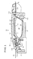
- Fig. 1 is a cross-sectional view illustrating a configuration of a door handle apparatus according to an embodiment taken along line I-I (i.e., middle line m) in Fig. 2 ;
- Fig. 2 is a front view illustrating the configuration of the door handle apparatus according to the embodiment, when seen from a side where the door handle apparatus is mounted (i.e., a side of a vehicle);
- Fig. 3 is an exploded perspective view illustrating a portion of the door handle apparatus according to the embodiment extending from a rotational-portion extending portion to a holding portion;
- Fig. 4 is a perspective view illustrating a lock detection electrode of the door handle apparatus according to the embodiment.
- Fig. 5 is a block diagram illustrating a configuration of an equivalent circuit and a door lock system of the door handle apparatus according to the embodiment
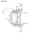
- Fig. 6 is a cross-sectional view illustrating the configuration of the door handle apparatus taken along line VI-VI in Fig. 1 ;
- Fig. 7 is a cross-sectional view illustrating the configuration of the door handle apparatus taken along line VII-VII in Fig. 6 ;
- Fig. 8 is a perspective view illustrating a lock detection electrode of the door handle apparatus according to a modified embodiment
- Fig. 9 is a front view illustrating a configuration of a conventional door handle apparatus.
- Fig. 10 is a cross-sectional view illustrating the configuration of the conventional door handle apparatus taken along line X-X in Fig. 9 .
- a door handle 10 of the door handle apparatus is configured by a splitable body, which may be split into two portions including a first handle case 11 and a second handle case 12.
- the first handle case 11 includes a holding portion 11a for holding the door handle 10, arranged to be distant away from an outer surface of an outer panel 20 of a vehicle door by a clearance GP.
- the second handle case 12 serves as an outer portion of the door handle 10 and is connected to the first handle case 11 by means of screws and the like, so as to cover the first handle case 11.
- the door handle 10 is configured by a splitable body, which may be split into two portions so that the door handle 10 is designed and manufactured more freely and more easily. Both of the first and second handle cases 11 and 12 are made of highly-rigid resin.
- the second handle case 12 includes a rotational-portion extending portion 12b, provided in the vicinity of one end portion of the handle case 12 in a longitudinal direction of the door handle 10, and extends so as to penetrate through the outer panel 20 of the vehicle door from a rotational portion 12a.
- the rotational portion 12a is rotatably supported by a supporting member 21, which is provided at an inner side of the outer panel 20.
- the second handle case 12 further includes an operational-portion extending portion 12d, provided in the vicinity of the other end portion of the second handle case 12 being more distant from the rotational-portion extending portion 12b than the holding portion 11a in the longitudinal direction of the door handle 10, and extending so as to penetrate through the outer panel 20 from an operational portion 12c.
- the operational portion 12c used for operating a lever 22 of a door opening and closing mechanism which is arranged at the inner side of the outer panel 20.
- the door handle 10 When a user pulls the door handle 10 in a manner of holding the holding portion 11a, the door handle 10 is pivoted about the rotational-portion extending portion 12b in a direction where the operational-portion extending portion 12d is pulled out. Consequently, unless the vehicle door is in a locked state, the lever 22 is operated by means of the operational portion 12c, and thereby the vehicle door is opened.
- a middle line m is set along a longitudinal direction of a portion extending from the rotational-portion extending portion 12b to the operational-portion extending portion 12d.
- an upper wall 12e and a lower wall 12f of the second handle case 12 is formed to be asymmetrical to each other relative to the middle line ("upper” and “lower” used hereinafter correspond to an upper and lower direction (or vertical direction) of the vehicle, respectively).
- An uneven-shaped serration 12g is formed on surfaces of the upper and lower walls 12e and 12f of the second handle case 12, though detailed description of a configuration of the serration 12g using a diagram is not provided.
- the serration 12g guides a water drop W, which may fall on surfaces of upper and lower walls 12e and 12f of the second handle case 12 due to rain and the like, to flow easily.
- the serration 12g also serves as a marking.
- a lock detection electrode 31 of a first electrostatic capacity sensor 41 (an electrostatic capacity sensor) is electrically connected to the circuit substrate 30.
- the first electrostatic capacity sensor 41 detects a command for locking the vehicle door (i.e., the command for locking the vehicle door is inputted in response to an operation of the user having an intention of locking the vehicle door) on the basis of fluctuation of the electrostatic capacity.
- the lock detection electrode 31 is arranged so as to face an inner surface of the second handle case 12.
- the lock detection electrode 31 integrally includes an upper lock detection electrode 36 and a lower lock detection electrode 37, which are arranged between the holding portion 11 a and the rotational-portion extending portion 12b so as to face inner surfaces of the upper and lower walls 12e and 12f of the second handle case 12, respectively.
- An unlock detection electrode 32 of a second electrostatic capacity sensor 42 is provided at an inner surface of the holding portion 11a of the first handle case 11 facing the second handle case 12.
- the second electrostatic capacity sensor 42 detects a command for unlocking the vehicle door on the basis of fluctuation of the electrostatic capacity (i.e., the command for unlocking the vehicle door is inputted in response to an operation of the user having an intention of unlocking the vehicle door).
- the unlock detection electrode 32 is electrically connected to an electrode, which is mounted on the circuit substrate 30 so as to serve as a sensor input terminal. Further, an antenna 33 is provided in the vicinity of the inner surface of the holding portion 11a of the first handle case 11.
- Information signals are transmitted between a portable device carried by the user and a door control portion 60 via the antenna 33 in order to authenticate the user, for example.
- the antenna 33 is electrically connected to an electrode, which is mounted on the circuit substrate 30 so as to serve as a feed terminal. Further, the antenna 33 and a sensor IC 40, which is connected to each of the first and second electrostatic capacity sensors 41 and 42 and is mounted on the circuit substrate 30, are supplied with electricity via a connector 34, which is provided at a back surface of the circuit substrate 30, while information signals outputted by the sensor IC 40 are inputted into the door control portion 60 via the connector 34.
- the upper lock detection electrode 36 and the lower lock detection electrode 37 of the lock detection electrode 31 are formed to be asymmetrical to each other relative to the above-mentioned middle line m of the door handle 10. More specifically, as illustrated in Fig. 4 , the upper lock detection electrode 36 is formed in a substantially trapezoid shape having a first short side 36a and a second short side 36b that is longer than the first short side 36a, at front and rear sides of the vehicle, respectively.
- the lower lock detection electrode 37 is formed into a substantially rectangular shape (i.e., the substantially rectangular shape is formed in a manner where a triangular-shaped end portion of a substantially trapezoid shape illustrated by a double-dashed line in Fig. 4 facing the outer panel 20 is cut out) having a third short side 37a and a fourth short side 37b at the front and rear side of the vehicle, respectively.
- a first electrode end surface 36c and a second electrode end surface 37c, which respectively serve as longitudinal sides of the upper and lower lock detection electrodes 36 and 37, and which face the outer panel 20, are formed into different shapes from each other.
- the upper and lower lock detection electrodes 36 and 37 are formed so that a distance between the outer panel 20 and the second electrode end surface 37c is longer than a distance between the outer panel 20 and the first electrode end surface 36c. Therefore, a level of capacitive coupling established between the outer panel 20 and the second electrode end surface 37c of the lower lock detection electrode 37 is smaller than a level of capacitive coupling established between the outer panel 20 and the first electrode end surface 36c of the upper lock detection electrode 36 by a level corresponding to a difference in distance between the outer panel 20 and each of the first and second electrode end surfaces 36c and 37c.
- the lock detection electrode 31 includes a plate-shaped connecting portion 38, which extends uprightly from the circuit substrate 30 for a predetermined height.
- a first end portion 38a and a second end portion 38b of the connecting portion 38 are bent so as to extend further uprightly from to the circuit substrate 30, and are connected to a first base end portion 36d of the upper lock detection electrode 36 and a second base end portion 37d of the lower lock detection electrode 37, respectively. Accordingly, the upper lock detection electrode 36 and the lower lock detection electrode 37 are integrally connected to each other via the connecting portion 38.
- the capacitive coupling having a value of electrostatic capacity C PANEL 1
- the capacitive coupling having an electrostatic capacity value C PANEL 2
- the capacitive coupling having an electrostatic capacity value C PANEL 2
- the first electrostatic capacity sensor 41 is inputted into the first electrostatic capacity sensor 41, which is connected to the sensor IC 40 via the lock detection electrode 31.
- the first electrostatic capacity sensor 41 detects that the command for locking the vehicle door is inputted, on the basis of the fact that the inputted sum of the electrostatic capacity is increased from the value of the electrostatic capacity C PANEL 1 by the value of electrostatic capacity C T .
- the door control portion 60 determines that the command for locking the vehicle door is inputted in response to an operation of the user, on the basis of the detection signal inputted into the first electrostatic capacity sensor 41. Consequently, the door control portion 60 controls to drive an actuator 81 for locking the vehicle door, which is provided at a locking mechanism 80, via a driver circuit 70, and thereby the vehicle door is locked.
- the above-described detection principle and the operation may be applied to an unlocking system, in which the vehicle door is unlocked by means of the unlock detection electrode 32 together with the second electrostatic capacity sensor 42, embedded in the sensor IC 40.
- the lock detection electrode 31 is arranged so as to face the inner surfaces of the upper and lower walls 12e and 12f of the second handle case 12. Therefore, even when the user holds the door handle, the command for locking the vehicle door may not be inputted in response to the holding operation of the door handle 10 by the user. In other words, an operational error may not occur with respect to a door lock operation of the user.
- the lock detection electrode 31 (the upper lock detection electrode 36 and the lower lock detection electrode 37) is arranged so as to face the upper and lower walls 12e and 12f of the second handle case 12. Further, a case of the door handle 10 is configured by the splitable body, which may be split into the first and second handle cases 11 and 12. Accordingly, the following issue may not be ignored. As illustrated in Fig. 6 with a cross-sectional view taken along line VI-VI in Fig. 1 , a space portion generated between the outer panel 20 and each of the first and second electrode end surfaces 36c and 37c of the upper and lower lock detection electrodes 36 and 37 becomes narrower when each detection range of the upper and lower lock detection electrodes 36 and 37 is expanded.
- the water drop W may easily flow into the space portion generated between the outer panel 20 and each of the electrode end surfaces 36c and 37c of the upper and lower lock detection electrodes 36 and 37. Further, because the case of the door handle 10 is configured by the splitable body, which may be split into the two portions, the water drop W may approach a vicinity of (i.e., come in contact with) the upper and lower lock detection electrodes 36 and 37.
- electrostatic capacitive components C PANEL 1 (W) and C PANEL 2 (W) may be increased because electric permittivity of dielectric body is increased at a portion between the outer panel 20 and each of the upper and lower lock detection electrodes 36 and 37 (more specifically, at a shortest facing portion), where capacitive coupling is established.
- the "shortest facing portion” mentioned hereinafter refers to a portion where the outer panel 20 and each of the upper and lower lock detection electrodes 36 and 37 face each other and a distance therebetween is shortest.
- the electrostatic capacitive component C PANEL 2 (W) may be increased. Consequently, the increased electrostatic capacitive component C PANEL 2 (W) may become a major part of the electrostatic capacity C PANEL , which is established between the lock detection electrode 31 and the outer panel 20, and as a result, the first electrostatic capacity sensor 41 may malfunction in response to an unintended command for locking the vehicle door.
- the upper and lower lock detection electrodes 36 and 37 are arranged in a manner where the distance between the outer panel 20 and the second electrode end surface 37c is longer than the distance between the outer panel 20 and the first electrode end surface 36c. Therefore the level of the capacitive coupling established between the outer panel 20 and the second electrode end surface 37c of the lower lock detection electrode 37 is set to be smaller than the level of the capacitive coupling established between the outer panel 20 and the first electrode end surface 36c of the upper lock detection electrode 36. Accordingly, as illustrated in Fig. 7 with a cross-sectional view taken along line VII-VII in Fig.
- a sufficient clearance is provided for allowing the fluctuation of the electric permittivity at the shortest facing portion between the outer panel 20 and the lower lock detection electrode 37 and the fluctuation of the electrostatic capacity, which may be caused by ingress of the water drop W, and the like. As a result, the ingress of the water drop W does not cause the first electrostatic sensor 41 to malfunction.
- the lock detection electrode 31 is arranged at the inner surfaces of the upper and lower walls 12e and 12f of the second handle case 12. Therefore, the command for locking the vehicle door may not be inputted in response to the holding operation of the door handle 10 by the user. More specifically, when the user holds the upper and lower walls 12e and 12f of the second handle case 12 between his/her fingers in order to input the command for locking the vehicle door, the command for locking the vehicle door is detected because dimensions of the detection area of the upper and lower lock detection electrodes 36 and 37 are sufficiently obtained. Further, because the water drop W flows from the upper to the lower portions of the door handle 10, the water drop W may easily accumulate at the lower portion of the door handle 10.
- the upper and lower lock detection electrodes 36 and 37 are formed into the different shapes from each other, so that the capacitive coupling established between the second electrode end surface 37c and the outer panel 20 is smaller than the capacitive coupling established between the first electrode end surface 36c and the outer panel 20.
- the upper and lower lock detection electrodes 36 and 37 are formed so that the distance between the outer panel 20 and the second electrode end surface 37c is set to be greater than the distance between the outer panel 20 and the first electrode end surface 36c. Therefore the water drop W is less likely to form the bridge between the outer panel 20 and the second electrode end surface 37c, compared to the first electrode end surface 36c.
- the sufficient clearance is provided for allowing the fluctuation of the electric permittivity at the shortest facing portion between the outer panel 20 and the lower lock detection electrode 37 and the fluctuation of the electrostatic capacity, which may be caused when the water drop W approaches (i.e., comes in contact with) the lower lock detection electrode 37.
- the water drop W is less likely to form the bridge between the outer panel 20 and the second electrode end surface 37c, at the lower lock detection electrode 37, which may be more likely to be affected by the water drop W.
- the first electrostatic capacity sensor 41 may not malfunction due to the water drop W.
- the above-described effects are not limited to be obtained relative to the water drop W caused by rain, and the similar effects may be obtained relative to water drop occurring when washing the vehicle.
- the upper and lower walls 12e and 12f of the second handle case 12 are formed to be asymmetrical to each other relative to the middle line m. Therefore, when the upper and lower lock detection electrodes 36 and 37, which respectively include the first and second electrode end surfaces 36c and 37c formed into the different shapes from each other, are arranged at the inner surfaces of the upper and lower walls 12e and 12f of the second handle case 12, the arrangement of the upper and lower lock detection electrodes 36 and 37 are not restricted by the shape of the second handle case 12. Further, the upper and lower walls 12e and 12f of the second handle case 12 do not need to be formed to be symmetrical to each other relative to the middle line m. Therefore, the door handle 10 may be more freely designed.
- the surfaces of the upper ad lower walls 12e and 12f of the second handle case 12 are formed into uneven shapes (i.e., the serration 12g) for guiding the water drop W falling on the surfaces thereof to flow easily. Therefore, the water drop W may not cause the malfunction of the first electrostatic capacity sensor 41.
- the lock detection electrode 31, which includes the first and second electrode end surfaces 36c and 37c (the upper and lower lock detection electrodes 36 and 37), is made of a metal plate and may easily be made by pressing the metal plate.
- the unlock detection electrode 32 for detecting the unlocking operation of the vehicle door is arranged at the inner side of the holding portion of the door handle 10. Therefore, a command for unlocking the vehicle door is inputted in response to the holding operation of the door handle 10 by the user, who intends to open the vehicle door. Accordingly, the command for locking the vehicle door and the command for unlocking the vehicle door are appropriately distinguished. In other words, user's intention of locking/unlocking the vehicle door is more accurately detected via the first and second electrostatic capacity sensors 41 and 42.
- Water proof sealing material or packing for covering at least the upper and lower lock detection electrodes 36 and 37 are not required. Further, the above-described embodiment may be modified as follows.
- a lock detection electrode 51 shown in Fig. 8 may be applied. More specifically, a lower lock detection electrode 52 of the lock detection electrode 51 is formed in a substantially pentagonal shape having a first short side 52a and a second short side 52b at the front and rear sides of the vehicle, respectively (i.e., the substantially pentagonal shape is formed in a manner where front and rear end portions of a substantially trapezoid shape (similar to a shape of the upper lock detection electrode 36, and illustrated by a double dashed line in Fig. 8 ) are cut out, and then, a substantially triangular-shaped portion is further cut out from the cutout rear end portion).
- a length of a second electrode end surface 52c, serving as a longer side and facing the outer panel 20, of the lower lock detection electrode 52 is set to be shorter than that of the first electrode end surface 36c of the upper lock detection electrode 36.
- a dimension of the second electrode end surface 52c of the lower lock detection electrode 52 is set to be smaller than that of the first electrode end surface of the upper lock detection electrode 36. Consequently, a level of capacitive coupling established between the outer panel 20 and the second electrode end surface 52c of the lower lock detection electrode 52 is smaller than a level of capacitive coupling established between the outer panel 20 and the first electrode end surface 36c of the upper lock detection electrode 36 by a level corresponding to a decreased dimension of the second electrode end surfaces 52c. Therefore, even when the embodiment is modified, the similar effects may be obtained.
- the dimension of the lower lock detection electrode 37, 52 may be set to be smaller than that of the upper lock detection electrode 36 in a manner where the lower lock detection electrode 37, 52 and the upper lock detection electrode 36 are similar to each other in shape but a thickness of the lower lock detection electrode 37, 52 is set to be smaller than that of the upper lock detection electrode 36.
- the first and second walls 12e and 12f of the second handle case 12 may be formed in to be symmetrical to each other relative to the middle line m.
- the rotational-portion extending portion 12b and the operational-portion extending portion 12d are provided at the second handle case 12.
- the embodiment may be applied to a door handle, in which each of or one of the rotational-portion extending portion 12b and the operational-portion extending portion 12d is provided at the first handle case 11.
- a door handle apparatus includes a door handle (10) including first and second handle cases (11, 12) constituting a door handle (10), a rotational-portion extending portion (12b), a operational-portion extending portion (12d), and a lock detection electrode (31, 51) of an electrostatic capacity sensor (41) detecting that a door lock command is inputted, on the basis of a fluctuation of electrostatic capacity.
- the lock detection electrode (31, 51) includes an upper lock detection electrode (36) and a lower lock detection electrode (37, 52) arranged to face an inner surface of an upper wall (12e) and an inner surface of a lower wall (12f), respectively.
- a first electrode end surface (36c) of the upper lock detection electrode (36) and a second electrode end surface (37c) of the lower lock detection electrode (37, 52) are formed into different shapes, so that a level of capacitive coupling between the lower lock detection electrode (37, 52) and the outer panel (20) is set to be smaller than a level of capacitive coupling between the upper lock detection electrode (36) and the outer panel (20).
Landscapes
- Lock And Its Accessories (AREA)
Abstract
Description
- The present invention relates to a door handle apparatus having a function of detecting a command for locking a vehicle door and the like.
- A door handle apparatus, on which a Smart Entry System (trademark) is mounted, is known, in which, for example, it is recognized that a user approaches a vehicle or that the user gets out of the vehicle, on the basis of a communication between a portable device, carried by the user, and a transmission device of the vehicle, while it is detected that a door lock command or a door unlock command is inputted by the user relative to a vehicle door in order to automatically execute locking and unlocking operations. Such door handle apparatus is disclosed in
JP3502848A - As illustrated in
Figs. 9 and 10 , according to the door handle apparatus disclosed inJP3502848A holding portion 110, at which a hand of the user may be inserted between anouter panel 200 of a vehicle door and adoor handle 100. Further, a lock sensor SLK for detecting a lock command of the user is arranged at an operational-portion extending portion 120, the operational-portion extending portion 120 being arranged at thedoor handle 100 to be adjacent to theholding portion 110 and extending from a portion for operating an opening and closing mechanism of the vehicle door. The lock sensor SLK and the unlock sensor SULK are electrostatic capacitance sensors, which detect a fluctuation of the electrostatic capacitance. The lock sensor SLK and the unlock sensor SULK detect the fluctuation of the electrostatic capacitance, which is generated when the hand of the user approaches a vicinity of each detection electrode of the lock sensor SLK and the unlock sensor SULK, and thereby determining that the lock command or the unlock command are inputted. More specifically, a value of electrostatic capacity CPANEL, which is established between theouter panel 200 of the vehicle door and the detection electrode of the lock sensor SLK, is set as a standard value, and when a value of electrostatic capacity detected by the lock sensor SLK does not fluctuate for a great extent from the value of electrostatic capacity CPANEL, it is determined that the unlock command is not inputted. When the hand of the user approaches the vicinity of the detection electrode, another electrostatic capacity CT is established between the detection electrode and the hand of the user so as to be in parallel with the electrostatic capacity CPANEL (i.e., CPANEL + CT). Therefore, when the value of the electrostatic capacity, detected by the lock sensor SLK, is increased by a level corresponding to the value of electrostatic capacity CT, it is determined that the lock command is inputted. The detection principle may be applied to the unlock sensor SULK. According to the door handle apparatus disclosed inJP3502848A door handle 100. Therefore, the lock command and the unlock command are detected in response to an operation of the user who touches the different portions of thedoor handle 100. - According to the door handle apparatus disclosed in
JP3502848A Fig. 10 , a lock detection electrode (the lock sensor SLK) is arranged at an end portion of an outer surface of the holding portion 110 (i.e., a surface of theholding portion 110 opposite from the outer panel 200). Therefore, when the user inserts his/her hand between theholding portion 110 and theouter panel 200 in order to unlock the vehicle door, and then pulls thedoor handle 100 in order to open the vehicle door, the user may accidentally touch a detection area of the lock sensor SLK with his/her hand. In such a case, both of the unlock command of the unlock sensor SLK and the lock command of the lock sensor SLK may be outputted simultaneously, and an appropriate command may not be inputted. Further, the user may touch the detection area of the lock sensor SLK with his/her hand when the vehicle door is opened, and thereby a locking operation may be unintentionally executed. Thus, an operation, which is not intended by the user, may be executed. - A need thus exists for a door handle apparatus, in which an operational error by a user is restricted.
- According to an aspect of the present invention, a door handle apparatus for a vehicle includes a door handle including a first handle case having a holding portion for holding the door handle, the holding portion arranged to be distant from an outer surface of an outer panel of a vehicle door by a clearance, a second handle case serving as an outer portion of the door handle and arranged to cover the first handle case, a rotational-portion extending portion provided in the vicinity of one end portion of the door handle in a longitudinal direction of the door handle and extending so as to penetrate through the outer panel from the rotational portion rotatably supported by a supporting member arranged at an inner side of the outer panel, a operational-portion extending portion provided in the vicinity of the other end portion of the door handle in the longitudinal direction of the door handle and extending so as to penetrate through the outer panel from the operational portion operating an opening and closing mechanism of the vehicle door, and a lock detection electrode of an electrostatic capacity sensor, the lock detection electrode being arranged to face an inner surface of the second handle case facing the outer panel, the electrostatic capacity sensor detecting that a door lock command is inputted, on the basis of a fluctuation of electrostatic capacity. The lock detection electrode includes an upper lock detection electrode and a lower lock detection electrode arranged to face an inner surface of an upper wall of the second handle case facing the outer panel and an inner surface of a lower wall of the second handle case facing the outer panel, respectively. A first electrode end surface of the upper lock detection electrode and a second electrode end surface of the lower lock detection electrode, each of which faces the outer panel, are formed into different shapes from each other, so that a level of capacitive coupling established between the lower lock detection electrode and the outer panel is set to be smaller than a level of capacitive coupling established between the upper lock detection electrode and the outer panel.
- Accordingly, the lock detection electrode (the upper lock detection electrode and the lower lock detection electrode) is arranged at the inner surfaces of the upper and lower walls of the second handle case. Therefore, a command for locking the vehicle door may not be inputted in response to the holding operation of the door handle by a user. More specifically, when the user holds the upper and lower walls of the second handle case between his/her fingers in order to input the command for locking the vehicle door, the command for locking the vehicle door is detected because dimension of the detection area of the upper and lower lock detection electrodes is sufficiently obtained. Further, because water drop flows from upper to the lower portions of the door handle, the water drop may easily accumulates at the lower portion of the door handle. However, the upper and lower lock detection electrodes are formed into the different shapes from each other, so that the capacitive coupling established between the second electrode end surface and the outer panel is smaller than the capacitive coupling established between the first electrode end surface and the outer panel. Therefore the water drop is less likely to form the bridge between the outer panel and the second electrode end surface, compared to the first electrode end surface. Accordingly, the sufficient clearance is provided for allowing the fluctuation of the electric permittivity at a shortest facing portion between the outer panel and the lower lock detection electrode and the fluctuation of the electrostatic capacity, which may be caused when the water drop approaches (i.e., comes in contact with) the lower lock detection electrode. Thus, the water drop is less likely to form the bridge between the outer panel and the second electrode end surface, at the lower lock detection electrode, which may be affected by the water drop. Accordingly, the electrostatic capacity sensor may not malfunction due to the water drop.
- According to another aspect of the invention, the second electrode end surface of the lower lock detection electrode is formed so that a distance between the second electrode end surface of the lower lock detection electrode and the outer panel is set to be greater than a distance between the first electrode end surface of the upper lock detection electrode and the outer panel.
- Accordingly, the capacitive coupling established between the second electrode end surface of the lower lock detection electrode and the outer panel is set to be relatively smaller than the capacitive coupling established between the first electrode end surface of the upper lock detection electrode.
- According to a further aspect of the invention, the second electrode end surface of the lower lock detection electrode is formed so that a dimension of the second electrode end surface of the lower lock detection electrode is set to be smaller than a dimension of the first electrode end surface of the upper lock detection electrode.
- Accordingly, the capacitive coupling established between the second electrode end surface of the lower lock detection electrode and the outer panel is set to be relatively smaller than the capacitive coupling established between the first
electrode end surface 36c of the upper lock detection electrode. - According to a further aspect of the invention, the upper wall and the lower wall of the second handle case are formed to be asymmetrical to each other relative to a middle line m, extending from the rotational-portion extending portion to the operational-portion extending portion.
- Accordingly, when the upper and lower lock detection electrodes, which respectively include the first and second electrode end surfaces formed into the different shapes from each other, are arranged at the inner surfaces of the upper and lower walls of the second handle case, the arrangement of the upper and lower lock detection electrodes is not restricted by the shape of the second handle case.
- According to a further aspect of the invention, the upper lock detection electrode and the lower lock detection electrode are integrally formed via a connecting portion.
- According to a further aspect of the invention, the upper lock detection electrode and the lower lock detection electrode are integrally formed by pressing a metal plate.
- Accordingly, an operational error by a user is restricted.
- The foregoing and additional features and characteristics of the present invention will become more apparent from the following detailed description considered with the reference to the accompanying drawings, wherein:
-
Fig. 1 is a cross-sectional view illustrating a configuration of a door handle apparatus according to an embodiment taken along line I-I (i.e., middle line m) inFig. 2 ; -
Fig. 2 is a front view illustrating the configuration of the door handle apparatus according to the embodiment, when seen from a side where the door handle apparatus is mounted (i.e., a side of a vehicle); -
Fig. 3 is an exploded perspective view illustrating a portion of the door handle apparatus according to the embodiment extending from a rotational-portion extending portion to a holding portion; -
Fig. 4 is a perspective view illustrating a lock detection electrode of the door handle apparatus according to the embodiment; -
Fig. 5 is a block diagram illustrating a configuration of an equivalent circuit and a door lock system of the door handle apparatus according to the embodiment; -
Fig. 6 is a cross-sectional view illustrating the configuration of the door handle apparatus taken along line VI-VI inFig. 1 ; -
Fig. 7 is a cross-sectional view illustrating the configuration of the door handle apparatus taken along line VII-VII inFig. 6 ; -
Fig. 8 is a perspective view illustrating a lock detection electrode of the door handle apparatus according to a modified embodiment; -
Fig. 9 is a front view illustrating a configuration of a conventional door handle apparatus; and -
Fig. 10 is a cross-sectional view illustrating the configuration of the conventional door handle apparatus taken along line X-X inFig. 9 . - An embodiment of a door handle apparatus, on which a Smart Entry System (trademark) is mounted, will be described hereinafter with reference to the attached
Figs. 1 to 7 . - As illustrated in
Fig. 1 , adoor handle 10 of the door handle apparatus is configured by a splitable body, which may be split into two portions including afirst handle case 11 and asecond handle case 12. Thefirst handle case 11 includes aholding portion 11a for holding thedoor handle 10, arranged to be distant away from an outer surface of anouter panel 20 of a vehicle door by a clearance GP. Thesecond handle case 12 serves as an outer portion of thedoor handle 10 and is connected to thefirst handle case 11 by means of screws and the like, so as to cover thefirst handle case 11. Thedoor handle 10 is configured by a splitable body, which may be split into two portions so that thedoor handle 10 is designed and manufactured more freely and more easily. Both of the first andsecond handle cases - The
second handle case 12 includes a rotational-portion extending portion 12b, provided in the vicinity of one end portion of thehandle case 12 in a longitudinal direction of thedoor handle 10, and extends so as to penetrate through theouter panel 20 of the vehicle door from arotational portion 12a. Therotational portion 12a is rotatably supported by a supportingmember 21, which is provided at an inner side of theouter panel 20. Likewise, thesecond handle case 12 further includes an operational-portion extending portion 12d, provided in the vicinity of the other end portion of thesecond handle case 12 being more distant from the rotational-portion extending portion 12b than theholding portion 11a in the longitudinal direction of thedoor handle 10, and extending so as to penetrate through theouter panel 20 from anoperational portion 12c. Theoperational portion 12c used for operating alever 22 of a door opening and closing mechanism, which is arranged at the inner side of theouter panel 20. When a user pulls thedoor handle 10 in a manner of holding the holdingportion 11a, thedoor handle 10 is pivoted about the rotational-portion extending portion 12b in a direction where the operational-portion extending portion 12d is pulled out. Consequently, unless the vehicle door is in a locked state, thelever 22 is operated by means of theoperational portion 12c, and thereby the vehicle door is opened. - A middle line m is set along a longitudinal direction of a portion extending from the rotational-
portion extending portion 12b to the operational-portion extending portion 12d. As illustrated inFig. 2 , anupper wall 12e and alower wall 12f of thesecond handle case 12 is formed to be asymmetrical to each other relative to the middle line ("upper" and "lower" used hereinafter correspond to an upper and lower direction (or vertical direction) of the vehicle, respectively). An uneven-shapedserration 12g is formed on surfaces of the upper andlower walls second handle case 12, though detailed description of a configuration of theserration 12g using a diagram is not provided. Theserration 12g guides a water drop W, which may fall on surfaces of upper andlower walls second handle case 12 due to rain and the like, to flow easily. Theserration 12g also serves as a marking. - A
circuit substrate 30, on which electric components are mounted, is assembled on a surface of thefirst handle case 11 facing thesecond handle case 12 and is arranged between the holdingportion 11a thereof and the rotational-portion extending portion 12b of thesecond handle case 12. Alock detection electrode 31 of a first electrostatic capacity sensor 41 (an electrostatic capacity sensor) is electrically connected to thecircuit substrate 30. The firstelectrostatic capacity sensor 41 detects a command for locking the vehicle door (i.e., the command for locking the vehicle door is inputted in response to an operation of the user having an intention of locking the vehicle door) on the basis of fluctuation of the electrostatic capacity. Thelock detection electrode 31 is arranged so as to face an inner surface of thesecond handle case 12. Thelock detection electrode 31 integrally includes an upperlock detection electrode 36 and a lowerlock detection electrode 37, which are arranged between the holdingportion 11 a and the rotational-portion extending portion 12b so as to face inner surfaces of the upper andlower walls second handle case 12, respectively. "Inner surface of the second handle case 12 (the upper andlower walls lower walls outer panel 20 of the vehicle door. - An
unlock detection electrode 32 of a secondelectrostatic capacity sensor 42 is provided at an inner surface of the holdingportion 11a of thefirst handle case 11 facing thesecond handle case 12. The secondelectrostatic capacity sensor 42 detects a command for unlocking the vehicle door on the basis of fluctuation of the electrostatic capacity (i.e., the command for unlocking the vehicle door is inputted in response to an operation of the user having an intention of unlocking the vehicle door). Theunlock detection electrode 32 is electrically connected to an electrode, which is mounted on thecircuit substrate 30 so as to serve as a sensor input terminal. Further, anantenna 33 is provided in the vicinity of the inner surface of the holdingportion 11a of thefirst handle case 11. Information signals are transmitted between a portable device carried by the user and adoor control portion 60 via theantenna 33 in order to authenticate the user, for example. Theantenna 33 is electrically connected to an electrode, which is mounted on thecircuit substrate 30 so as to serve as a feed terminal. Further, theantenna 33 and asensor IC 40, which is connected to each of the first and secondelectrostatic capacity sensors circuit substrate 30, are supplied with electricity via aconnector 34, which is provided at a back surface of thecircuit substrate 30, while information signals outputted by thesensor IC 40 are inputted into thedoor control portion 60 via theconnector 34. - A detailed description of a configuration of the
lock detection electrode 31 will be described hereinafter with reference toFigs. 3 and4 . - As illustrated in
Fig. 3 , the upperlock detection electrode 36 and the lowerlock detection electrode 37 of thelock detection electrode 31 are formed to be asymmetrical to each other relative to the above-mentioned middle line m of thedoor handle 10. More specifically, as illustrated inFig. 4 , the upperlock detection electrode 36 is formed in a substantially trapezoid shape having a firstshort side 36a and a secondshort side 36b that is longer than the firstshort side 36a, at front and rear sides of the vehicle, respectively. On the other hand, the lowerlock detection electrode 37 is formed into a substantially rectangular shape (i.e., the substantially rectangular shape is formed in a manner where a triangular-shaped end portion of a substantially trapezoid shape illustrated by a double-dashed line inFig. 4 facing theouter panel 20 is cut out) having a thirdshort side 37a and a fourthshort side 37b at the front and rear side of the vehicle, respectively. A firstelectrode end surface 36c and a secondelectrode end surface 37c, which respectively serve as longitudinal sides of the upper and lowerlock detection electrodes outer panel 20, are formed into different shapes from each other. The upper and lowerlock detection electrodes outer panel 20 and the secondelectrode end surface 37c is longer than a distance between theouter panel 20 and the firstelectrode end surface 36c. Therefore, a level of capacitive coupling established between theouter panel 20 and the secondelectrode end surface 37c of the lowerlock detection electrode 37 is smaller than a level of capacitive coupling established between theouter panel 20 and the firstelectrode end surface 36c of the upperlock detection electrode 36 by a level corresponding to a difference in distance between theouter panel 20 and each of the first and second electrode end surfaces 36c and 37c. - The
lock detection electrode 31 includes a plate-shaped connectingportion 38, which extends uprightly from thecircuit substrate 30 for a predetermined height. Afirst end portion 38a and asecond end portion 38b of the connectingportion 38 are bent so as to extend further uprightly from to thecircuit substrate 30, and are connected to a firstbase end portion 36d of the upperlock detection electrode 36 and a secondbase end portion 37d of the lowerlock detection electrode 37, respectively. Accordingly, the upperlock detection electrode 36 and the lowerlock detection electrode 37 are integrally connected to each other via the connectingportion 38. - A detection principle and an operation with respect to a door lock will be described hereinafter with reference to
Fig. 5 . - As illustrated in
Fig. 5 , according to the door handle apparatus shown inFig. 1 , the capacitive coupling, having a value ofelectrostatic capacity C PANEL 1, is established between the upperlock detection electrode 36 and theouter panel 20 of the vehicle door, serving as a first ground GND1, while the capacitive coupling, having an electrostaticcapacity value C PANEL 2, is established between the lowerlock detection electrode 37 and theouter panel 20 of the vehicle door, serving as the first ground GND1. A sum of the values of the electrostatic capacity CPANEL (i.e., CPANEL =C PANEL 1 + CPANEL 2) is inputted into the firstelectrostatic capacity sensor 41, which is connected to thesensor IC 40 via thelock detection electrode 31. - When the user touches a portion of the
second handle case 12 of thedoor handle 10, facing to the lock detection electrode 31 (the upperlock detection electrode 36 and the lower locking operation detecting operation 37) with his/her hand, another capacitive coupling, having a value of electrostatic capacity CT, is established between thelock detection electrode 31 and the user, which serves as a second ground GND2, so as to be electrically in parallel with the above-described capacitive coupling, having the values ofelectrostatic capacity C PANEL 1 andC PANEL 2. A sum of the values of electrostatic capacity (CPANEL + CT) is inputted into the firstelectrostatic capacity sensor 41. Consequently, the firstelectrostatic capacity sensor 41 detects that the command for locking the vehicle door is inputted, on the basis of the fact that the inputted sum of the electrostatic capacity is increased from the value of theelectrostatic capacity C PANEL 1 by the value of electrostatic capacity CT. When the firstelectrostatic capacity sensor 41 detects that the command for locking the vehicle door is inputted, thedoor control portion 60 determines that the command for locking the vehicle door is inputted in response to an operation of the user, on the basis of the detection signal inputted into the firstelectrostatic capacity sensor 41. Consequently, thedoor control portion 60 controls to drive anactuator 81 for locking the vehicle door, which is provided at alocking mechanism 80, via adriver circuit 70, and thereby the vehicle door is locked. The above-described detection principle and the operation may be applied to an unlocking system, in which the vehicle door is unlocked by means of theunlock detection electrode 32 together with the secondelectrostatic capacity sensor 42, embedded in thesensor IC 40. As described above, in the door handle apparatus according to the embodiment, thelock detection electrode 31 is arranged so as to face the inner surfaces of the upper andlower walls second handle case 12. Therefore, even when the user holds the door handle, the command for locking the vehicle door may not be inputted in response to the holding operation of thedoor handle 10 by the user. In other words, an operational error may not occur with respect to a door lock operation of the user. - As described above, the lock detection electrode 31 (the upper
lock detection electrode 36 and the lower lock detection electrode 37) is arranged so as to face the upper andlower walls second handle case 12. Further, a case of thedoor handle 10 is configured by the splitable body, which may be split into the first and second handlecases Fig. 6 with a cross-sectional view taken along line VI-VI inFig. 1 , a space portion generated between theouter panel 20 and each of the first and second electrode end surfaces 36c and 37c of the upper and lowerlock detection electrodes lock detection electrodes outer panel 20 and each of the electrode end surfaces 36c and 37c of the upper and lowerlock detection electrodes door handle 10 is configured by the splitable body, which may be split into the two portions, the water drop W may approach a vicinity of (i.e., come in contact with) the upper and lowerlock detection electrodes lock detection electrodes outer panel 20 and each of the upper and lowerlock detection electrodes 36 and 37 (more specifically, at a shortest facing portion), where capacitive coupling is established. The "shortest facing portion" mentioned hereinafter refers to a portion where theouter panel 20 and each of the upper and lowerlock detection electrodes door handle 10, water may accumulate at an inside of the lower portion of thedoor handle 10, and therefore, the electrostatic capacitive component CPANEL 2 (W) may be increased. Consequently, the increased electrostatic capacitive component CPANEL 2 (W) may become a major part of the electrostatic capacity CPANEL, which is established between thelock detection electrode 31 and theouter panel 20, and as a result, the firstelectrostatic capacity sensor 41 may malfunction in response to an unintended command for locking the vehicle door. - On the other hand, in the door handle apparatus according to the embodiment, the upper and lower
lock detection electrodes outer panel 20 and the secondelectrode end surface 37c is longer than the distance between theouter panel 20 and the firstelectrode end surface 36c. Therefore the level of the capacitive coupling established between theouter panel 20 and the secondelectrode end surface 37c of the lowerlock detection electrode 37 is set to be smaller than the level of the capacitive coupling established between theouter panel 20 and the firstelectrode end surface 36c of the upperlock detection electrode 36. Accordingly, as illustrated inFig. 7 with a cross-sectional view taken along line VII-VII inFig. 6 , when the water drop W flows into the space portion between theouter panel 20 and the secondelectrode end surface 37c of the lowerlock detection electrode 37, the water drop W is less likely to form a bridge between theouter panel 20 and the secondelectrode end surface 37c, because the secondelectrode end surface 37c is distant away from theouter panel 20 for a longer distance. Consequently, even when the water drop W approaches the vicinity of (i.e., comes in contact with) the lowerlock detection electrode 37, the electrostatic capacitive component CPANEL 2 (W) may not be increased. In other words, a sufficient clearance is provided for allowing the fluctuation of the electric permittivity at the shortest facing portion between theouter panel 20 and the lowerlock detection electrode 37 and the fluctuation of the electrostatic capacity, which may be caused by ingress of the water drop W, and the like. As a result, the ingress of the water drop W does not cause the firstelectrostatic sensor 41 to malfunction. - As described above, the following effects may be obtained in the door handle apparatus according to the embodiment.
- The
lock detection electrode 31 is arranged at the inner surfaces of the upper andlower walls second handle case 12. Therefore, the command for locking the vehicle door may not be inputted in response to the holding operation of thedoor handle 10 by the user. More specifically, when the user holds the upper andlower walls second handle case 12 between his/her fingers in order to input the command for locking the vehicle door, the command for locking the vehicle door is detected because dimensions of the detection area of the upper and lowerlock detection electrodes door handle 10, the water drop W may easily accumulate at the lower portion of thedoor handle 10. However, the upper and lowerlock detection electrodes electrode end surface 37c and theouter panel 20 is smaller than the capacitive coupling established between the firstelectrode end surface 36c and theouter panel 20. In other words, the upper and lowerlock detection electrodes outer panel 20 and the secondelectrode end surface 37c is set to be greater than the distance between theouter panel 20 and the firstelectrode end surface 36c. Therefore the water drop W is less likely to form the bridge between theouter panel 20 and the secondelectrode end surface 37c, compared to the firstelectrode end surface 36c. Accordingly, the sufficient clearance is provided for allowing the fluctuation of the electric permittivity at the shortest facing portion between theouter panel 20 and the lowerlock detection electrode 37 and the fluctuation of the electrostatic capacity, which may be caused when the water drop W approaches (i.e., comes in contact with) the lowerlock detection electrode 37. Thus, the water drop W is less likely to form the bridge between theouter panel 20 and the secondelectrode end surface 37c, at the lowerlock detection electrode 37, which may be more likely to be affected by the water drop W. Accordingly, the firstelectrostatic capacity sensor 41 may not malfunction due to the water drop W. Further, the above-described effects are not limited to be obtained relative to the water drop W caused by rain, and the similar effects may be obtained relative to water drop occurring when washing the vehicle. - The upper and
lower walls second handle case 12 are formed to be asymmetrical to each other relative to the middle line m. Therefore, when the upper and lowerlock detection electrodes lower walls second handle case 12, the arrangement of the upper and lowerlock detection electrodes second handle case 12. Further, the upper andlower walls second handle case 12 do not need to be formed to be symmetrical to each other relative to the middle line m. Therefore, thedoor handle 10 may be more freely designed. - The surfaces of the upper ad
lower walls second handle case 12 are formed into uneven shapes (i.e., theserration 12g) for guiding the water drop W falling on the surfaces thereof to flow easily. Therefore, the water drop W may not cause the malfunction of the firstelectrostatic capacity sensor 41. - The
lock detection electrode 31, which includes the first and second electrode end surfaces 36c and 37c (the upper and lowerlock detection electrodes 36 and 37), is made of a metal plate and may easily be made by pressing the metal plate. - The
unlock detection electrode 32 for detecting the unlocking operation of the vehicle door is arranged at the inner side of the holding portion of thedoor handle 10. Therefore, a command for unlocking the vehicle door is inputted in response to the holding operation of thedoor handle 10 by the user, who intends to open the vehicle door. Accordingly, the command for locking the vehicle door and the command for unlocking the vehicle door are appropriately distinguished. In other words, user's intention of locking/unlocking the vehicle door is more accurately detected via the first and secondelectrostatic capacity sensors - Water proof sealing material or packing for covering at least the upper and lower
lock detection electrodes - A
lock detection electrode 51 shown inFig. 8 may be applied. More specifically, a lowerlock detection electrode 52 of thelock detection electrode 51 is formed in a substantially pentagonal shape having a firstshort side 52a and a secondshort side 52b at the front and rear sides of the vehicle, respectively (i.e., the substantially pentagonal shape is formed in a manner where front and rear end portions of a substantially trapezoid shape (similar to a shape of the upperlock detection electrode 36, and illustrated by a double dashed line inFig. 8 ) are cut out, and then, a substantially triangular-shaped portion is further cut out from the cutout rear end portion). In such a case, a length of a secondelectrode end surface 52c, serving as a longer side and facing theouter panel 20, of the lowerlock detection electrode 52 is set to be shorter than that of the firstelectrode end surface 36c of the upperlock detection electrode 36. In other words, a dimension of the secondelectrode end surface 52c of the lowerlock detection electrode 52 is set to be smaller than that of the first electrode end surface of the upperlock detection electrode 36. Consequently, a level of capacitive coupling established between theouter panel 20 and the secondelectrode end surface 52c of the lowerlock detection electrode 52 is smaller than a level of capacitive coupling established between theouter panel 20 and the firstelectrode end surface 36c of the upperlock detection electrode 36 by a level corresponding to a decreased dimension of the secondelectrode end surfaces 52c. Therefore, even when the embodiment is modified, the similar effects may be obtained. - Further, the dimension of the lower
lock detection electrode lock detection electrode 36 in a manner where the lowerlock detection electrode lock detection electrode 36 are similar to each other in shape but a thickness of the lowerlock detection electrode lock detection electrode 36. - In the above-described embodiment, as long as the
second handle case 12 does not interfere with the accommodation of the lock detection electrode 31 (the upper and lowerlock detection electrodes 36 and 37), the first andsecond walls second handle case 12 may be formed in to be symmetrical to each other relative to the middle line m. - According to the embodiment, the rotational-
portion extending portion 12b and the operational-portion extending portion 12d are provided at thesecond handle case 12. However, the embodiment may be applied to a door handle, in which each of or one of the rotational-portion extending portion 12b and the operational-portion extending portion 12d is provided at thefirst handle case 11. - The surfaces of the upper and
lower walls second handle case 12 are formed into uneven shapes for guiding the water drop W falling on the surfaces thereof to flow easily. According to such structure, for example, malfunction of the first and secondelectrostatic capacity sensors
A door handle apparatus includes a door handle (10) including first and second handle cases (11, 12) constituting a door handle (10), a rotational-portion extending portion (12b), a operational-portion extending portion (12d), and a lock detection electrode (31, 51) of an electrostatic capacity sensor (41) detecting that a door lock command is inputted, on the basis of a fluctuation of electrostatic capacity. The lock detection electrode (31, 51) includes an upper lock detection electrode (36) and a lower lock detection electrode (37, 52) arranged to face an inner surface of an upper wall (12e) and an inner surface of a lower wall (12f), respectively. A first electrode end surface (36c) of the upper lock detection electrode (36) and a second electrode end surface (37c) of the lower lock detection electrode (37, 52) are formed into different shapes, so that a level of capacitive coupling between the lower lock detection electrode (37, 52) and the outer panel (20) is set to be smaller than a level of capacitive coupling between the upper lock detection electrode (36) and the outer panel (20).
Claims (6)
- A door handle apparatus for a vehicle comprising:a door handle (10) including a first handle case (11) and a second handle case (12), the first handle case (11) having a holding portion (11a) for holding the door handle (10), the holding portion (11a) being arranged to be distant from an outer surface of an outer panel (20) of a vehicle door with a clearance (GP), the second handle case (12) serving as an outer portion of the door handle apparatus (10) and arranged to cover the first handle case (11);a rotational-portion extending portion (12b) provided in the vicinity of one end portion of the door handle (10) in a longitudinal direction thereof and extending into the outer panel (20) after passing therethrough to connect a rotational portion (12a) that is rotatably supported by a supporting member (21) inside the outer panel (20); andan operational-portion extending portion (12d) formed in the vicinity of the other end portion of the door handle (10) in the longitudinal direction thereof and extending into the outer panel (20) after passing therethrough to connect an operational portion (12c) operating an opening and closing mechanism of the vehicle door, the operational-portion extending portion (12d) being provided with a lock detection electrode (31, 51) of an electrostatic capacity sensor (41),the lock detection electrode (31, 51) being arranged to face an inner surface of the second handle case (12) facing the outer panel (20), the electrostatic capacity sensor (41) detecting that a door lock command is inputted, on the basis of a fluctuation of electrostatic capacity, whereinthe lock detection electrode (31, 51) includes an upper lock detection electrode (36) and a lower lock detection electrode (37, 52) arranged to face an inner surface of an upper wall (12e) of the second handle case (12) facing the outer panel (20) and an inner surface of a lower wall (12f) of the second handle case (12) facing the outer panel (20), respectively, and wherein
a first electrode end surface (36c) of the upper lock detection electrode (36) and a second electrode end surface (37c) of the lower lock detection electrode (37, 52), each of which faces the outer panel (20), are formed into different shapes from each other, so that a level of capacitive coupling established between the lower lock detection electrode (37, 52) and the outer panel (20) is set to be smaller than a level of capacitive coupling established between the upper lock detection electrode (36) and the outer panel (20). - The door handle apparatus according to Claim 1, wherein
the second electrode end surface (37c, 52c) of the lower lock detection electrode (37, 52) is formed so that a distance between the second electrode end surface (37c, 52c) of the lower lock detection electrode (37, 52) and the outer panel (20) is set to be greater than a distance between the first electrode end surface (36c) of the upper lock detection electrode (36) and the outer panel (20). - The door handle apparatus according to Claim 1, wherein
the second electrode end surface (37c, 52c) of the lower lock detection electrode (37, 52) is formed so that a dimension of the second electrode end surface (37c, 52c) of the lower lock detection electrode (37, 52) is set to be smaller than a dimension of the first electrode end surface (36c) of the upper lock detection electrode (36). - The door handle apparatus according to any one of Claims 1 to 3, wherein the upper wall (12e) and the lower wall (12f) of the second handle case (12) are formed to be asymmetrical to each other relative to a middle line m, extending from the rotational-portion extending portion (12b) to the operational-portion extending portion (12d).
- The door handle apparatus according to Claim 1, wherein
the upper lock detection electrode (36) and the lower lock detection electrode (37, 52) are integrally formed via a connecting portion (38). - The door handle apparatus according to Claim 5, wherein
the upper lock detection electrode (36) and the lower lock detection electrode (37, 52) are integrally formed by pressing a metal plate.
Applications Claiming Priority (1)
| Application Number | Priority Date | Filing Date | Title |
|---|---|---|---|
| JP2008191079A JP5131472B2 (en) | 2008-07-24 | 2008-07-24 | Door handle device |
Publications (3)
| Publication Number | Publication Date |
|---|---|
| EP2148025A2 true EP2148025A2 (en) | 2010-01-27 |
| EP2148025A3 EP2148025A3 (en) | 2013-10-09 |
| EP2148025B1 EP2148025B1 (en) | 2014-09-24 |
Family
ID=41319768
Family Applications (1)
| Application Number | Title | Priority Date | Filing Date |
|---|---|---|---|
| EP20090166178 Not-in-force EP2148025B1 (en) | 2008-07-24 | 2009-07-23 | Door handle apparatus |
Country Status (3)
| Country | Link |
|---|---|
| US (1) | US8408610B2 (en) |
| EP (1) | EP2148025B1 (en) |
| JP (1) | JP5131472B2 (en) |
Cited By (6)
| Publication number | Priority date | Publication date | Assignee | Title |
|---|---|---|---|---|
| US20100187838A1 (en) * | 2007-07-27 | 2010-07-29 | Aisin Seiki Kabushiki Kaisha | Door handle device |
| US20120133159A1 (en) * | 2010-11-26 | 2012-05-31 | Aisin Seiki Kabushiki Kaisha | Door handle apparatus |
| US20120167642A1 (en) * | 2009-11-20 | 2012-07-05 | Valeo S.P.A. | Vehicle unlocking control device provided with an outer control member having an over-molded mounting |
| EP2412897A3 (en) * | 2010-07-26 | 2012-10-31 | Aisin Seiki Kabushiki Kaisha | Door handle device for vehicle |
| CN103909899A (en) * | 2013-01-09 | 2014-07-09 | 通用汽车环球科技运作有限责任公司 | Vehicle door latch system and method |
| CN104763253A (en) * | 2014-01-07 | 2015-07-08 | 上海海拉电子有限公司 | Door knob assembly, automobile door knob and mounting method thereof |
Families Citing this family (17)
| Publication number | Priority date | Publication date | Assignee | Title |
|---|---|---|---|---|
| JP5480112B2 (en) | 2010-11-29 | 2014-04-23 | 株式会社ユーシン | ANTENNA UNIT AND DOOR HANDLE DEVICE HAVING THE SAME |
| DE102011056818A1 (en) * | 2011-12-21 | 2013-06-27 | Huf Hülsbeck & Fürst Gmbh & Co. Kg | Motor vehicle door handle with encapsulated electronic component |
| CN102747893B (en) * | 2012-04-27 | 2016-02-24 | 黄正男 | A kind of touch lock device for door of car |
| USD712232S1 (en) * | 2013-03-07 | 2014-09-02 | Paccar Inc | Door release |
| US9002584B2 (en) | 2013-03-19 | 2015-04-07 | Ford Global Technologies, Llc | Rain onset detection glazing auto-close |
| JP6064806B2 (en) * | 2013-06-21 | 2017-01-25 | アイシン精機株式会社 | Vehicle door handle |
| JP6529859B2 (en) * | 2014-10-01 | 2019-06-12 | 株式会社ユーシン | Proximity sensor and keyless entry device having the same |
| JP6651710B2 (en) * | 2015-05-08 | 2020-02-19 | 三井金属アクト株式会社 | Door lock device for automobile |
| CN107849866B (en) * | 2015-07-13 | 2020-09-25 | 胡夫·许尔斯贝克和福斯特有限及两合公司 | Outside door handles for vehicles |
| US9752370B2 (en) | 2015-07-13 | 2017-09-05 | Ford Global Technologies, Llc | Rain onset detection auto-close user interface |
| CN109415916B (en) * | 2016-07-08 | 2021-08-20 | 本田技研工业株式会社 | door structure |
| DE102016010493A1 (en) * | 2016-08-31 | 2018-03-01 | Huf Hülsbeck & Fürst Gmbh & Co. Kg | Motor vehicle door handle assembly with sealed electronics space |
| DE102017008340A1 (en) * | 2017-09-05 | 2019-03-07 | Huf Hülsbeck & Fürst Gmbh & Co. Kg | Motor vehicle door handle assembly with embedded electronics |
| JP2021080626A (en) * | 2018-03-23 | 2021-05-27 | アルプスアルパイン株式会社 | Door handle |
| EP3770364B1 (en) | 2018-03-23 | 2023-04-05 | Alps Alpine Co., Ltd. | Door handle |
| JP2020126764A (en) * | 2019-02-05 | 2020-08-20 | ホシデン株式会社 | Proximity sensor and door handle device including the same |
| CN116411746B (en) * | 2021-12-30 | 2024-10-29 | 比亚迪股份有限公司 | Vehicle door control method and device, vehicle and computer storage medium |
Citations (1)
| Publication number | Priority date | Publication date | Assignee | Title |
|---|---|---|---|---|
| JP3502848B2 (en) | 2001-03-28 | 2004-03-02 | 株式会社ホンダロック | Device for confirming vehicle door opening / locking |
Family Cites Families (30)
| Publication number | Priority date | Publication date | Assignee | Title |
|---|---|---|---|---|
| JP3509790B2 (en) * | 2000-08-09 | 2004-03-22 | アイシン精機株式会社 | Vehicle door lock device |
| FR2813630B1 (en) * | 2000-09-05 | 2003-08-01 | Valeo Electronique | METHOD FOR AUTOMATICALLY LOCKING A VEHICLE OPENING ELEMENT WITH A HANDS-FREE ACCESS SYSTEM AND AN APPROACH SENSOR |
| US7126453B2 (en) * | 2001-02-21 | 2006-10-24 | Kiekert Ag | Keyless system for actuating a motor-vehicle door latch |
| JP3566943B2 (en) * | 2001-07-02 | 2004-09-15 | アイシン精機株式会社 | Vehicle door handle |
| FR2828225B1 (en) * | 2001-08-01 | 2003-10-31 | Valeo Electronique | OPENING HANDLE FOR MOTOR VEHICLE |
| DE60223405T2 (en) | 2001-10-01 | 2008-08-21 | Donnelly Corp., Holland | VEHICLE GRIP ASSEMBLY WITH ANTENNA |
| JP3619505B2 (en) * | 2001-11-20 | 2005-02-09 | 株式会社ホンダロック | Vehicle door handle device |
| WO2003071068A1 (en) | 2002-02-22 | 2003-08-28 | Schaffner Emv Ag | Induction coil, in particular for a vehicle door locking system |
| WO2003071067A1 (en) | 2002-02-22 | 2003-08-28 | Schaffner Emv Ag | Electronic control circuit comprising a proximity sensor and a transceiver for a vehicle door locking system |
| JP2004060191A (en) * | 2002-07-25 | 2004-02-26 | Aisin Seiki Co Ltd | Vehicle door handle |
| DE10255439B4 (en) * | 2002-11-28 | 2008-07-17 | Daimler Ag | Handle arrangement for a vehicle door |
| JP2004257126A (en) * | 2003-02-26 | 2004-09-16 | Aisin Seiki Co Ltd | Vehicle door opening and closing device |
| US7057124B2 (en) * | 2003-04-22 | 2006-06-06 | Aisin Seiki Kabushiki Kaisha | Push switch apparatus |
| JP4009953B2 (en) * | 2003-05-14 | 2007-11-21 | オムロン株式会社 | Object detection sensor |
| DE10336335B4 (en) * | 2003-08-08 | 2015-03-12 | Huf Hülsbeck & Fürst Gmbh & Co. Kg | Locking device for vehicles |
| CA2539713A1 (en) * | 2003-09-26 | 2005-04-07 | Matsushita Electric Industrial Co., Ltd. | Door handle device and keyless entry device having the same |
| JP2005113475A (en) * | 2003-10-07 | 2005-04-28 | Aisin Seiki Co Ltd | Door handle device |
| DE602005021841D1 (en) * | 2004-03-30 | 2010-07-29 | Honda Lock Kk | Door handle assembly for a motor vehicle door |
| DE102004046903A1 (en) * | 2004-09-28 | 2006-03-30 | Robert Bosch Gmbh | Request signal producing device for access authorization system of motor vehicle, has locally separate sensor fields with one part logically linked with one another and displaced in horizontal direction |
| DE102004063009A1 (en) | 2004-12-22 | 2006-07-13 | Huf Hülsbeck & Fürst Gmbh & Co. Kg | Device for actuating an electric locking system and / or a lock built into the door or flap or the like for vehicles |
| JP2006344554A (en) * | 2005-06-10 | 2006-12-21 | Stanley Electric Co Ltd | Capacitance type door touch sensor |
| JP2007039920A (en) * | 2005-08-01 | 2007-02-15 | Toyota Motor Corp | Vehicle handle device |
| JP4639141B2 (en) * | 2005-11-18 | 2011-02-23 | 株式会社ホンダロック | Antenna built-in device |
| JP4600323B2 (en) * | 2006-03-15 | 2010-12-15 | アイシン精機株式会社 | Vehicle door handle |
| JP4947348B2 (en) * | 2006-09-13 | 2012-06-06 | アイシン精機株式会社 | Vehicle door handle device |
| JP2008108534A (en) * | 2006-10-25 | 2008-05-08 | Fujikura Ltd | Human body approach detection device |
| JP4751860B2 (en) | 2007-07-27 | 2011-08-17 | アイシン精機株式会社 | Door handle device |
| JP4751861B2 (en) * | 2007-07-27 | 2011-08-17 | アイシン精機株式会社 | Door handle device |
| JP4938580B2 (en) | 2007-07-27 | 2012-05-23 | アイシン精機株式会社 | Door handle device |
| JP5092717B2 (en) * | 2007-11-30 | 2012-12-05 | トヨタ自動車株式会社 | Capacitive contact detector |
-
2008
- 2008-07-24 JP JP2008191079A patent/JP5131472B2/en not_active Expired - Fee Related
-
2009
- 2009-07-21 US US12/506,781 patent/US8408610B2/en active Active
- 2009-07-23 EP EP20090166178 patent/EP2148025B1/en not_active Not-in-force
Patent Citations (1)
| Publication number | Priority date | Publication date | Assignee | Title |
|---|---|---|---|---|
| JP3502848B2 (en) | 2001-03-28 | 2004-03-02 | 株式会社ホンダロック | Device for confirming vehicle door opening / locking |
Cited By (9)
| Publication number | Priority date | Publication date | Assignee | Title |
|---|---|---|---|---|
| US20100187838A1 (en) * | 2007-07-27 | 2010-07-29 | Aisin Seiki Kabushiki Kaisha | Door handle device |
| US20120167642A1 (en) * | 2009-11-20 | 2012-07-05 | Valeo S.P.A. | Vehicle unlocking control device provided with an outer control member having an over-molded mounting |
| US10253530B2 (en) * | 2009-11-20 | 2019-04-09 | U-Shin Italia S.P.A. | Vehicle unlocking control device provided with an outer control member having an over-molded mounting |
| EP2412897A3 (en) * | 2010-07-26 | 2012-10-31 | Aisin Seiki Kabushiki Kaisha | Door handle device for vehicle |
| US9033379B2 (en) | 2010-07-26 | 2015-05-19 | Aisin Seiki Kabushiki Kaisha | Door handle device for vehicle |
| US20120133159A1 (en) * | 2010-11-26 | 2012-05-31 | Aisin Seiki Kabushiki Kaisha | Door handle apparatus |
| CN103909899A (en) * | 2013-01-09 | 2014-07-09 | 通用汽车环球科技运作有限责任公司 | Vehicle door latch system and method |
| CN104763253A (en) * | 2014-01-07 | 2015-07-08 | 上海海拉电子有限公司 | Door knob assembly, automobile door knob and mounting method thereof |
| CN104763253B (en) * | 2014-01-07 | 2017-02-22 | 上海海拉电子有限公司 | Door knob assembly, automobile door knob and mounting method thereof |
Also Published As
| Publication number | Publication date |
|---|---|
| US20100019510A1 (en) | 2010-01-28 |
| JP2010024797A (en) | 2010-02-04 |
| US8408610B2 (en) | 2013-04-02 |
| EP2148025B1 (en) | 2014-09-24 |
| EP2148025A3 (en) | 2013-10-09 |
| JP5131472B2 (en) | 2013-01-30 |
Similar Documents
| Publication | Publication Date | Title |
|---|---|---|
| EP2148025B1 (en) | Door handle apparatus | |
| EP2177695B1 (en) | Door handle device | |
| EP2175091B1 (en) | Door handle device | |
| JP5022483B2 (en) | Vehicle door handle device | |
| JP4751860B2 (en) | Door handle device | |
| EP2458119A2 (en) | Door handle apparatus | |
| US20050236846A1 (en) | Vehicle door outer handle system | |
| CN107849865A (en) | Door handle facility for motor vehicle | |
| CN101663827A (en) | Interference filtering device suitable for sensors sensitive to electromagnetic waves and related filtering method | |
| WO2018008671A1 (en) | Door structure | |
| JP4970143B2 (en) | Door opener | |
| JP2021194934A (en) | Kick sensor attachment structure | |
| US20150340173A1 (en) | Door window opening and closing switch assembly | |
| JP4535762B2 (en) | Vehicle door handle device | |
| JP2014156753A (en) | Door handle device | |
| KR102529900B1 (en) | Open switching device integrated with emblem |
Legal Events
| Date | Code | Title | Description |
|---|---|---|---|
| PUAI | Public reference made under article 153(3) epc to a published international application that has entered the european phase |
Free format text: ORIGINAL CODE: 0009012 |
|
| AK | Designated contracting states |
Kind code of ref document: A2 Designated state(s): AT BE BG CH CY CZ DE DK EE ES FI FR GB GR HR HU IE IS IT LI LT LU LV MC MK MT NL NO PL PT RO SE SI SK SM TR |
|
| AX | Request for extension of the european patent |
Extension state: AL BA RS |
|
| PUAL | Search report despatched |
Free format text: ORIGINAL CODE: 0009013 |
|
| AK | Designated contracting states |
Kind code of ref document: A3 Designated state(s): AT BE BG CH CY CZ DE DK EE ES FI FR GB GR HR HU IE IS IT LI LT LU LV MC MK MT NL NO PL PT RO SE SI SK SM TR |
|
| AX | Request for extension of the european patent |
Extension state: AL BA RS |
|
| RIC1 | Information provided on ipc code assigned before grant |
Ipc: E05B 17/22 20060101ALI20130905BHEP Ipc: E05B 7/00 20060101AFI20130905BHEP Ipc: E05B 47/00 20060101ALI20130905BHEP Ipc: E05B 65/12 20060101ALI20130905BHEP |
|
| 17P | Request for examination filed |
Effective date: 20131108 |
|
| RBV | Designated contracting states (corrected) |
Designated state(s): AT BE BG CH CY CZ DE DK EE ES FI FR GB GR HR HU IE IS IT LI LT LU LV MC MK MT NL NO PL PT RO SE SI SK SM TR |
|
| REG | Reference to a national code |
Ref country code: DE Ref legal event code: R079 Ref document number: 602009026801 Country of ref document: DE Free format text: PREVIOUS MAIN CLASS: E05B0007000000 Ipc: E05B0077340000 |
|
| RIC1 | Information provided on ipc code assigned before grant |
Ipc: E05B 77/34 20140101AFI20140204BHEP |
|
| GRAP | Despatch of communication of intention to grant a patent |
Free format text: ORIGINAL CODE: EPIDOSNIGR1 |
|
| INTG | Intention to grant announced |
Effective date: 20140414 |
|
| GRAS | Grant fee paid |
Free format text: ORIGINAL CODE: EPIDOSNIGR3 |
|
| GRAA | (expected) grant |
Free format text: ORIGINAL CODE: 0009210 |
|
| AK | Designated contracting states |
Kind code of ref document: B1 Designated state(s): AT BE BG CH CY CZ DE DK EE ES FI FR GB GR HR HU IE IS IT LI LT LU LV MC MK MT NL NO PL PT RO SE SI SK SM TR |
|
| REG | Reference to a national code |
Ref country code: GB Ref legal event code: FG4D |
|
| REG | Reference to a national code |
Ref country code: CH Ref legal event code: EP |
|
| REG | Reference to a national code |
Ref country code: AT Ref legal event code: REF Ref document number: 688733 Country of ref document: AT Kind code of ref document: T Effective date: 20141015 |
|
| REG | Reference to a national code |
Ref country code: IE Ref legal event code: FG4D |
|
| REG | Reference to a national code |
Ref country code: DE Ref legal event code: R096 Ref document number: 602009026801 Country of ref document: DE Effective date: 20141106 |
|
| PG25 | Lapsed in a contracting state [announced via postgrant information from national office to epo] |
Ref country code: LT Free format text: LAPSE BECAUSE OF FAILURE TO SUBMIT A TRANSLATION OF THE DESCRIPTION OR TO PAY THE FEE WITHIN THE PRESCRIBED TIME-LIMIT Effective date: 20140924 Ref country code: GR Free format text: LAPSE BECAUSE OF FAILURE TO SUBMIT A TRANSLATION OF THE DESCRIPTION OR TO PAY THE FEE WITHIN THE PRESCRIBED TIME-LIMIT Effective date: 20141225 Ref country code: NO Free format text: LAPSE BECAUSE OF FAILURE TO SUBMIT A TRANSLATION OF THE DESCRIPTION OR TO PAY THE FEE WITHIN THE PRESCRIBED TIME-LIMIT Effective date: 20141224 Ref country code: FI Free format text: LAPSE BECAUSE OF FAILURE TO SUBMIT A TRANSLATION OF THE DESCRIPTION OR TO PAY THE FEE WITHIN THE PRESCRIBED TIME-LIMIT Effective date: 20140924 Ref country code: SE Free format text: LAPSE BECAUSE OF FAILURE TO SUBMIT A TRANSLATION OF THE DESCRIPTION OR TO PAY THE FEE WITHIN THE PRESCRIBED TIME-LIMIT Effective date: 20140924 |
|
| REG | Reference to a national code |
Ref country code: LT Ref legal event code: MG4D Ref country code: NL Ref legal event code: VDEP Effective date: 20140924 |
|
| PG25 | Lapsed in a contracting state [announced via postgrant information from national office to epo] |
Ref country code: HR Free format text: LAPSE BECAUSE OF FAILURE TO SUBMIT A TRANSLATION OF THE DESCRIPTION OR TO PAY THE FEE WITHIN THE PRESCRIBED TIME-LIMIT Effective date: 20140924 Ref country code: CY Free format text: LAPSE BECAUSE OF FAILURE TO SUBMIT A TRANSLATION OF THE DESCRIPTION OR TO PAY THE FEE WITHIN THE PRESCRIBED TIME-LIMIT Effective date: 20140924 Ref country code: LV Free format text: LAPSE BECAUSE OF FAILURE TO SUBMIT A TRANSLATION OF THE DESCRIPTION OR TO PAY THE FEE WITHIN THE PRESCRIBED TIME-LIMIT Effective date: 20140924 |
|
| REG | Reference to a national code |
Ref country code: AT Ref legal event code: MK05 Ref document number: 688733 Country of ref document: AT Kind code of ref document: T Effective date: 20140924 |
|
| PG25 | Lapsed in a contracting state [announced via postgrant information from national office to epo] |
Ref country code: NL Free format text: LAPSE BECAUSE OF FAILURE TO SUBMIT A TRANSLATION OF THE DESCRIPTION OR TO PAY THE FEE WITHIN THE PRESCRIBED TIME-LIMIT Effective date: 20140924 |
|
| PG25 | Lapsed in a contracting state [announced via postgrant information from national office to epo] |
Ref country code: CZ Free format text: LAPSE BECAUSE OF FAILURE TO SUBMIT A TRANSLATION OF THE DESCRIPTION OR TO PAY THE FEE WITHIN THE PRESCRIBED TIME-LIMIT Effective date: 20140924 Ref country code: SK Free format text: LAPSE BECAUSE OF FAILURE TO SUBMIT A TRANSLATION OF THE DESCRIPTION OR TO PAY THE FEE WITHIN THE PRESCRIBED TIME-LIMIT Effective date: 20140924 Ref country code: EE Free format text: LAPSE BECAUSE OF FAILURE TO SUBMIT A TRANSLATION OF THE DESCRIPTION OR TO PAY THE FEE WITHIN THE PRESCRIBED TIME-LIMIT Effective date: 20140924 Ref country code: IS Free format text: LAPSE BECAUSE OF FAILURE TO SUBMIT A TRANSLATION OF THE DESCRIPTION OR TO PAY THE FEE WITHIN THE PRESCRIBED TIME-LIMIT Effective date: 20150124 Ref country code: ES Free format text: LAPSE BECAUSE OF FAILURE TO SUBMIT A TRANSLATION OF THE DESCRIPTION OR TO PAY THE FEE WITHIN THE PRESCRIBED TIME-LIMIT Effective date: 20140924 Ref country code: PT Free format text: LAPSE BECAUSE OF FAILURE TO SUBMIT A TRANSLATION OF THE DESCRIPTION OR TO PAY THE FEE WITHIN THE PRESCRIBED TIME-LIMIT Effective date: 20150126 Ref country code: RO Free format text: LAPSE BECAUSE OF FAILURE TO SUBMIT A TRANSLATION OF THE DESCRIPTION OR TO PAY THE FEE WITHIN THE PRESCRIBED TIME-LIMIT Effective date: 20140924 |
|
| PG25 | Lapsed in a contracting state [announced via postgrant information from national office to epo] |
Ref country code: AT Free format text: LAPSE BECAUSE OF FAILURE TO SUBMIT A TRANSLATION OF THE DESCRIPTION OR TO PAY THE FEE WITHIN THE PRESCRIBED TIME-LIMIT Effective date: 20140924 Ref country code: PL Free format text: LAPSE BECAUSE OF FAILURE TO SUBMIT A TRANSLATION OF THE DESCRIPTION OR TO PAY THE FEE WITHIN THE PRESCRIBED TIME-LIMIT Effective date: 20140924 |
|
| REG | Reference to a national code |
Ref country code: DE Ref legal event code: R097 Ref document number: 602009026801 Country of ref document: DE |
|
| PG25 | Lapsed in a contracting state [announced via postgrant information from national office to epo] |
Ref country code: DK Free format text: LAPSE BECAUSE OF FAILURE TO SUBMIT A TRANSLATION OF THE DESCRIPTION OR TO PAY THE FEE WITHIN THE PRESCRIBED TIME-LIMIT Effective date: 20140924 |
|
| PLBE | No opposition filed within time limit |
Free format text: ORIGINAL CODE: 0009261 |
|
| STAA | Information on the status of an ep patent application or granted ep patent |
Free format text: STATUS: NO OPPOSITION FILED WITHIN TIME LIMIT |
|
| PG25 | Lapsed in a contracting state [announced via postgrant information from national office to epo] |
Ref country code: IT Free format text: LAPSE BECAUSE OF FAILURE TO SUBMIT A TRANSLATION OF THE DESCRIPTION OR TO PAY THE FEE WITHIN THE PRESCRIBED TIME-LIMIT Effective date: 20140924 |
|
| 26N | No opposition filed |
Effective date: 20150625 |
|
| PG25 | Lapsed in a contracting state [announced via postgrant information from national office to epo] |
Ref country code: SI Free format text: LAPSE BECAUSE OF FAILURE TO SUBMIT A TRANSLATION OF THE DESCRIPTION OR TO PAY THE FEE WITHIN THE PRESCRIBED TIME-LIMIT Effective date: 20140924 Ref country code: MC Free format text: LAPSE BECAUSE OF FAILURE TO SUBMIT A TRANSLATION OF THE DESCRIPTION OR TO PAY THE FEE WITHIN THE PRESCRIBED TIME-LIMIT Effective date: 20140924 |
|
| REG | Reference to a national code |
Ref country code: CH Ref legal event code: PL |
|
| GBPC | Gb: european patent ceased through non-payment of renewal fee |
Effective date: 20150723 |
|
| REG | Reference to a national code |
Ref country code: FR Ref legal event code: PLFP Year of fee payment: 8 |
|
| PG25 | Lapsed in a contracting state [announced via postgrant information from national office to epo] |
Ref country code: LU Free format text: LAPSE BECAUSE OF FAILURE TO SUBMIT A TRANSLATION OF THE DESCRIPTION OR TO PAY THE FEE WITHIN THE PRESCRIBED TIME-LIMIT Effective date: 20150723 |
|
| REG | Reference to a national code |
Ref country code: IE Ref legal event code: MM4A |
|
| PG25 | Lapsed in a contracting state [announced via postgrant information from national office to epo] |
Ref country code: CH Free format text: LAPSE BECAUSE OF NON-PAYMENT OF DUE FEES Effective date: 20150731 Ref country code: GB Free format text: LAPSE BECAUSE OF NON-PAYMENT OF DUE FEES Effective date: 20150723 Ref country code: LI Free format text: LAPSE BECAUSE OF NON-PAYMENT OF DUE FEES Effective date: 20150731 |
|
| PG25 | Lapsed in a contracting state [announced via postgrant information from national office to epo] |
Ref country code: IE Free format text: LAPSE BECAUSE OF NON-PAYMENT OF DUE FEES Effective date: 20150723 |
|
| PG25 | Lapsed in a contracting state [announced via postgrant information from national office to epo] |
Ref country code: MT Free format text: LAPSE BECAUSE OF FAILURE TO SUBMIT A TRANSLATION OF THE DESCRIPTION OR TO PAY THE FEE WITHIN THE PRESCRIBED TIME-LIMIT Effective date: 20140924 |
|
| PG25 | Lapsed in a contracting state [announced via postgrant information from national office to epo] |
Ref country code: HU Free format text: LAPSE BECAUSE OF FAILURE TO SUBMIT A TRANSLATION OF THE DESCRIPTION OR TO PAY THE FEE WITHIN THE PRESCRIBED TIME-LIMIT; INVALID AB INITIO Effective date: 20090723 Ref country code: SM Free format text: LAPSE BECAUSE OF FAILURE TO SUBMIT A TRANSLATION OF THE DESCRIPTION OR TO PAY THE FEE WITHIN THE PRESCRIBED TIME-LIMIT Effective date: 20140924 Ref country code: BG Free format text: LAPSE BECAUSE OF FAILURE TO SUBMIT A TRANSLATION OF THE DESCRIPTION OR TO PAY THE FEE WITHIN THE PRESCRIBED TIME-LIMIT Effective date: 20140924 |
|
| REG | Reference to a national code |
Ref country code: FR Ref legal event code: PLFP Year of fee payment: 9 |
|
| PG25 | Lapsed in a contracting state [announced via postgrant information from national office to epo] |
Ref country code: TR Free format text: LAPSE BECAUSE OF FAILURE TO SUBMIT A TRANSLATION OF THE DESCRIPTION OR TO PAY THE FEE WITHIN THE PRESCRIBED TIME-LIMIT Effective date: 20140924 |
|
| PG25 | Lapsed in a contracting state [announced via postgrant information from national office to epo] |
Ref country code: BE Free format text: LAPSE BECAUSE OF FAILURE TO SUBMIT A TRANSLATION OF THE DESCRIPTION OR TO PAY THE FEE WITHIN THE PRESCRIBED TIME-LIMIT Effective date: 20140924 |
|
| REG | Reference to a national code |
Ref country code: FR Ref legal event code: PLFP Year of fee payment: 10 |
|
| PG25 | Lapsed in a contracting state [announced via postgrant information from national office to epo] |
Ref country code: MK Free format text: LAPSE BECAUSE OF FAILURE TO SUBMIT A TRANSLATION OF THE DESCRIPTION OR TO PAY THE FEE WITHIN THE PRESCRIBED TIME-LIMIT Effective date: 20140924 |
|
| PGFP | Annual fee paid to national office [announced via postgrant information from national office to epo] |
Ref country code: FR Payment date: 20190619 Year of fee payment: 11 |
|
| PGFP | Annual fee paid to national office [announced via postgrant information from national office to epo] |
Ref country code: DE Payment date: 20190710 Year of fee payment: 11 |
|
| REG | Reference to a national code |
Ref country code: DE Ref legal event code: R119 Ref document number: 602009026801 Country of ref document: DE |
|
| PG25 | Lapsed in a contracting state [announced via postgrant information from national office to epo] |
Ref country code: FR Free format text: LAPSE BECAUSE OF NON-PAYMENT OF DUE FEES Effective date: 20200731 |
|
| PG25 | Lapsed in a contracting state [announced via postgrant information from national office to epo] |
Ref country code: DE Free format text: LAPSE BECAUSE OF NON-PAYMENT OF DUE FEES Effective date: 20210202 |