EP2147830A1 - Method and apparatus for assessing driver head pose with a headrest-mounted relative motion sensor - Google Patents
Method and apparatus for assessing driver head pose with a headrest-mounted relative motion sensor Download PDFInfo
- Publication number
- EP2147830A1 EP2147830A1 EP09162799A EP09162799A EP2147830A1 EP 2147830 A1 EP2147830 A1 EP 2147830A1 EP 09162799 A EP09162799 A EP 09162799A EP 09162799 A EP09162799 A EP 09162799A EP 2147830 A1 EP2147830 A1 EP 2147830A1
- Authority
- EP
- European Patent Office
- Prior art keywords
- headrest
- driver
- head
- relative motion
- motion sensor
- Prior art date
- Legal status (The legal status is an assumption and is not a legal conclusion. Google has not performed a legal analysis and makes no representation as to the accuracy of the status listed.)
- Granted
Links
Images

Classifications
-
- A—HUMAN NECESSITIES
- A61—MEDICAL OR VETERINARY SCIENCE; HYGIENE
- A61B—DIAGNOSIS; SURGERY; IDENTIFICATION
- A61B5/00—Measuring for diagnostic purposes; Identification of persons
- A61B5/16—Devices for psychotechnics; Testing reaction times ; Devices for evaluating the psychological state
- A61B5/18—Devices for psychotechnics; Testing reaction times ; Devices for evaluating the psychological state for vehicle drivers or machine operators
-
- B—PERFORMING OPERATIONS; TRANSPORTING
- B60—VEHICLES IN GENERAL
- B60N—SEATS SPECIALLY ADAPTED FOR VEHICLES; VEHICLE PASSENGER ACCOMMODATION NOT OTHERWISE PROVIDED FOR
- B60N2/00—Seats specially adapted for vehicles; Arrangement or mounting of seats in vehicles
- B60N2/002—Seats provided with an occupancy detection means mounted therein or thereon
- B60N2/0021—Seats provided with an occupancy detection means mounted therein or thereon characterised by the type of sensor or measurement
- B60N2/0024—Seats provided with an occupancy detection means mounted therein or thereon characterised by the type of sensor or measurement for identifying, categorising or investigation of the occupant or object on the seat
- B60N2/0027—Seats provided with an occupancy detection means mounted therein or thereon characterised by the type of sensor or measurement for identifying, categorising or investigation of the occupant or object on the seat for detecting the position of the occupant or of occupant's body part
- B60N2/0028—Seats provided with an occupancy detection means mounted therein or thereon characterised by the type of sensor or measurement for identifying, categorising or investigation of the occupant or object on the seat for detecting the position of the occupant or of occupant's body part of a body part, e.g. of an arm or a leg
-
- B—PERFORMING OPERATIONS; TRANSPORTING
- B60—VEHICLES IN GENERAL
- B60N—SEATS SPECIALLY ADAPTED FOR VEHICLES; VEHICLE PASSENGER ACCOMMODATION NOT OTHERWISE PROVIDED FOR
- B60N2/00—Seats specially adapted for vehicles; Arrangement or mounting of seats in vehicles
- B60N2/002—Seats provided with an occupancy detection means mounted therein or thereon
- B60N2/0021—Seats provided with an occupancy detection means mounted therein or thereon characterised by the type of sensor or measurement
- B60N2/0024—Seats provided with an occupancy detection means mounted therein or thereon characterised by the type of sensor or measurement for identifying, categorising or investigation of the occupant or object on the seat
- B60N2/0029—Seats provided with an occupancy detection means mounted therein or thereon characterised by the type of sensor or measurement for identifying, categorising or investigation of the occupant or object on the seat for detecting the motion of the occupant
-
- B—PERFORMING OPERATIONS; TRANSPORTING
- B60—VEHICLES IN GENERAL
- B60N—SEATS SPECIALLY ADAPTED FOR VEHICLES; VEHICLE PASSENGER ACCOMMODATION NOT OTHERWISE PROVIDED FOR
- B60N2/00—Seats specially adapted for vehicles; Arrangement or mounting of seats in vehicles
- B60N2/002—Seats provided with an occupancy detection means mounted therein or thereon
- B60N2/0021—Seats provided with an occupancy detection means mounted therein or thereon characterised by the type of sensor or measurement
- B60N2/003—Seats provided with an occupancy detection means mounted therein or thereon characterised by the type of sensor or measurement characterised by the sensor mounting location in or on the seat
-
- B—PERFORMING OPERATIONS; TRANSPORTING
- B60—VEHICLES IN GENERAL
- B60N—SEATS SPECIALLY ADAPTED FOR VEHICLES; VEHICLE PASSENGER ACCOMMODATION NOT OTHERWISE PROVIDED FOR
- B60N2/00—Seats specially adapted for vehicles; Arrangement or mounting of seats in vehicles
- B60N2/02—Seats specially adapted for vehicles; Arrangement or mounting of seats in vehicles the seat or part thereof being movable, e.g. adjustable
- B60N2/0224—Non-manual adjustments, e.g. with electrical operation
- B60N2/0244—Non-manual adjustments, e.g. with electrical operation with logic circuits
- B60N2/0273—Non-manual adjustments, e.g. with electrical operation with logic circuits taking into account user data, e.g. knee height or physical state
-
- B—PERFORMING OPERATIONS; TRANSPORTING
- B60—VEHICLES IN GENERAL
- B60N—SEATS SPECIALLY ADAPTED FOR VEHICLES; VEHICLE PASSENGER ACCOMMODATION NOT OTHERWISE PROVIDED FOR
- B60N2/00—Seats specially adapted for vehicles; Arrangement or mounting of seats in vehicles
- B60N2/80—Head-rests
- B60N2/806—Head-rests movable or adjustable
-
- B—PERFORMING OPERATIONS; TRANSPORTING
- B60—VEHICLES IN GENERAL
- B60N—SEATS SPECIALLY ADAPTED FOR VEHICLES; VEHICLE PASSENGER ACCOMMODATION NOT OTHERWISE PROVIDED FOR
- B60N2/00—Seats specially adapted for vehicles; Arrangement or mounting of seats in vehicles
- B60N2/80—Head-rests
- B60N2/806—Head-rests movable or adjustable
- B60N2/809—Head-rests movable or adjustable vertically slidable
- B60N2/829—Head-rests movable or adjustable vertically slidable characterised by their adjusting mechanisms, e.g. electric motors
-
- B—PERFORMING OPERATIONS; TRANSPORTING
- B60—VEHICLES IN GENERAL
- B60N—SEATS SPECIALLY ADAPTED FOR VEHICLES; VEHICLE PASSENGER ACCOMMODATION NOT OTHERWISE PROVIDED FOR
- B60N2/00—Seats specially adapted for vehicles; Arrangement or mounting of seats in vehicles
- B60N2/80—Head-rests
- B60N2/806—Head-rests movable or adjustable
- B60N2/865—Head-rests movable or adjustable providing a fore-and-aft movement with respect to the occupant's head
-
- B—PERFORMING OPERATIONS; TRANSPORTING
- B60—VEHICLES IN GENERAL
- B60N—SEATS SPECIALLY ADAPTED FOR VEHICLES; VEHICLE PASSENGER ACCOMMODATION NOT OTHERWISE PROVIDED FOR
- B60N2/00—Seats specially adapted for vehicles; Arrangement or mounting of seats in vehicles
- B60N2/80—Head-rests
- B60N2/879—Head-rests with additional features not related to head-rest positioning, e.g. heating or cooling devices or loudspeakers
-
- B—PERFORMING OPERATIONS; TRANSPORTING
- B60—VEHICLES IN GENERAL
- B60R—VEHICLES, VEHICLE FITTINGS, OR VEHICLE PARTS, NOT OTHERWISE PROVIDED FOR
- B60R21/00—Arrangements or fittings on vehicles for protecting or preventing injuries to occupants or pedestrians in case of accidents or other traffic risks
- B60R21/01—Electrical circuits for triggering passive safety arrangements, e.g. airbags, safety belt tighteners, in case of vehicle accidents or impending vehicle accidents
- B60R21/015—Electrical circuits for triggering passive safety arrangements, e.g. airbags, safety belt tighteners, in case of vehicle accidents or impending vehicle accidents including means for detecting the presence or position of passengers, passenger seats or child seats, and the related safety parameters therefor, e.g. speed or timing of airbag inflation in relation to occupant position or seat belt use
- B60R21/01512—Passenger detection systems
- B60R21/0153—Passenger detection systems using field detection presence sensors
- B60R21/01534—Passenger detection systems using field detection presence sensors using electromagneticwaves, e.g. infrared
-
- B—PERFORMING OPERATIONS; TRANSPORTING
- B60—VEHICLES IN GENERAL
- B60R—VEHICLES, VEHICLE FITTINGS, OR VEHICLE PARTS, NOT OTHERWISE PROVIDED FOR
- B60R21/00—Arrangements or fittings on vehicles for protecting or preventing injuries to occupants or pedestrians in case of accidents or other traffic risks
- B60R21/01—Electrical circuits for triggering passive safety arrangements, e.g. airbags, safety belt tighteners, in case of vehicle accidents or impending vehicle accidents
- B60R21/015—Electrical circuits for triggering passive safety arrangements, e.g. airbags, safety belt tighteners, in case of vehicle accidents or impending vehicle accidents including means for detecting the presence or position of passengers, passenger seats or child seats, and the related safety parameters therefor, e.g. speed or timing of airbag inflation in relation to occupant position or seat belt use
- B60R21/01512—Passenger detection systems
- B60R21/01552—Passenger detection systems detecting position of specific human body parts, e.g. face, eyes or hands
-
- G—PHYSICS
- G06—COMPUTING OR CALCULATING; COUNTING
- G06V—IMAGE OR VIDEO RECOGNITION OR UNDERSTANDING
- G06V20/00—Scenes; Scene-specific elements
- G06V20/50—Context or environment of the image
- G06V20/59—Context or environment of the image inside of a vehicle, e.g. relating to seat occupancy, driver state or inner lighting conditions
- G06V20/597—Recognising the driver's state or behaviour, e.g. attention or drowsiness
-
- G—PHYSICS
- G06—COMPUTING OR CALCULATING; COUNTING
- G06V—IMAGE OR VIDEO RECOGNITION OR UNDERSTANDING
- G06V40/00—Recognition of biometric, human-related or animal-related patterns in image or video data
- G06V40/20—Movements or behaviour, e.g. gesture recognition
-
- B—PERFORMING OPERATIONS; TRANSPORTING
- B60—VEHICLES IN GENERAL
- B60N—SEATS SPECIALLY ADAPTED FOR VEHICLES; VEHICLE PASSENGER ACCOMMODATION NOT OTHERWISE PROVIDED FOR
- B60N2210/00—Sensor types, e.g. for passenger detection systems or for controlling seats
- B60N2210/10—Field detection presence sensors
- B60N2210/16—Electromagnetic waves
- B60N2210/22—Optical; Photoelectric; Lidar [Light Detection and Ranging]
-
- B—PERFORMING OPERATIONS; TRANSPORTING
- B60—VEHICLES IN GENERAL
- B60N—SEATS SPECIALLY ADAPTED FOR VEHICLES; VEHICLE PASSENGER ACCOMMODATION NOT OTHERWISE PROVIDED FOR
- B60N2230/00—Communication or electronic aspects
- B60N2230/30—Signal processing of sensor data
-
- B—PERFORMING OPERATIONS; TRANSPORTING
- B60—VEHICLES IN GENERAL
- B60R—VEHICLES, VEHICLE FITTINGS, OR VEHICLE PARTS, NOT OTHERWISE PROVIDED FOR
- B60R21/00—Arrangements or fittings on vehicles for protecting or preventing injuries to occupants or pedestrians in case of accidents or other traffic risks
- B60R2021/003—Arrangements or fittings on vehicles for protecting or preventing injuries to occupants or pedestrians in case of accidents or other traffic risks characterised by occupant or pedestian
- B60R2021/0039—Body parts of the occupant or pedestrian affected by the accident
- B60R2021/0048—Head
-
- B—PERFORMING OPERATIONS; TRANSPORTING
- B60—VEHICLES IN GENERAL
- B60R—VEHICLES, VEHICLE FITTINGS, OR VEHICLE PARTS, NOT OTHERWISE PROVIDED FOR
- B60R21/00—Arrangements or fittings on vehicles for protecting or preventing injuries to occupants or pedestrians in case of accidents or other traffic risks
- B60R21/01—Electrical circuits for triggering passive safety arrangements, e.g. airbags, safety belt tighteners, in case of vehicle accidents or impending vehicle accidents
- B60R2021/01204—Actuation parameters of safety arrangents
- B60R2021/01252—Devices other than bags
-
- B—PERFORMING OPERATIONS; TRANSPORTING
- B60—VEHICLES IN GENERAL
- B60W—CONJOINT CONTROL OF VEHICLE SUB-UNITS OF DIFFERENT TYPE OR DIFFERENT FUNCTION; CONTROL SYSTEMS SPECIALLY ADAPTED FOR HYBRID VEHICLES; ROAD VEHICLE DRIVE CONTROL SYSTEMS FOR PURPOSES NOT RELATED TO THE CONTROL OF A PARTICULAR SUB-UNIT
- B60W2540/00—Input parameters relating to occupants
- B60W2540/22—Psychological state; Stress level or workload
-
- B—PERFORMING OPERATIONS; TRANSPORTING
- B60—VEHICLES IN GENERAL
- B60W—CONJOINT CONTROL OF VEHICLE SUB-UNITS OF DIFFERENT TYPE OR DIFFERENT FUNCTION; CONTROL SYSTEMS SPECIALLY ADAPTED FOR HYBRID VEHICLES; ROAD VEHICLE DRIVE CONTROL SYSTEMS FOR PURPOSES NOT RELATED TO THE CONTROL OF A PARTICULAR SUB-UNIT
- B60W2540/00—Input parameters relating to occupants
- B60W2540/221—Physiology, e.g. weight, heartbeat, health or special needs
-
- G—PHYSICS
- G06—COMPUTING OR CALCULATING; COUNTING
- G06F—ELECTRIC DIGITAL DATA PROCESSING
- G06F2218/00—Aspects of pattern recognition specially adapted for signal processing
Definitions
- the present invention is relates to driver distraction monitoring in motor vehicles with a relative motion sensor mounted in a headrest of the driver's seat, and more particularly to a method and apparatus for adjusting the headrest position to optimize both the safety of the driver and the sensitivity of the relative motion sensor.
- a driver monitoring system for determining if the driver is paying attention to the forward field-of-view. This information can be used to issue an alert if the driver's attention is directed away from the road too long or too often, and possibly to belay other warnings (such as collision-avoidance warnings) if the driver is paying attention to the forward field-of-view.
- An example of such a monitoring system is Delphi Corporation's Driver State Monitor, which processes a video image of the driver's face to detect and track the driver's eyes for assessing eye gaze.
- the present invention provides an improved method and apparatus for assessing the head pose of a vehicle driver with a relative motion sensor mounted in a headrest of the driver's seat, and for adjusting the headrest position to optimize both the safety of the driver and the sensitivity of the relative motion sensor.
- the relative motion sensor is used to adjust the position of the headrest relative to the driver's head for optimal driver safety, and the relative motion sensor is configured to provide optimal sensitivity for head pose assessment when the headrest is positioned for driver safety.
- FIG. 1 diagrammatically depicts a vehicle passenger compartment with a driver occupying a seat equipped with an adjustable headrest and a headrest-mounted relative motion sensing system;
- FIG. 2 is an isometric diagram of the headrest and relative motion sensing system of FIG. 1 ;
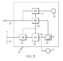
- FIG. 3 is a system block diagram of the sensing system of FIGS. 1-2 , including a processor for controlling headrest adjustment and assessing driver head pose;
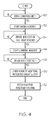
- FIG. 4 is a flow diagram representing a software routine carried out by the processor of FIG. 3 for controlling headrest adjustment
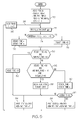
- FIG. 5 is a flow diagram representing a software routine carried out by the processor of FIG. 3 for assessing driver head pose.
- the present invention is directed to assessment of driver head pose by sensing driver head motion with a headrest-mounted relative motion sensor, where the sensor output is used to position the headrest for optimal driver safety and the sensor is oriented within headrest 12 to provide optimal sensitivity to driver head motion when the headrest is so positioned.
- the invention is disclosed in the context of a driver distraction system that determines if the driver's attention is forward or non-forward relative to the forward direction of vehicle motion, but the head pose assessment may be directed to other aspects of driver behavior, as will be understood by those skilled in the art.
- the headrest adjustment is performed automatically through suitable activation a power adjustable headrest, but the adjustment may alternatively be performed manually by the driver in response to prompts provided by the sensing system in applications where the driver seat is not equipped with a power adjustable headrest.
- the reference numeral 10 generally designates a motor vehicle passenger compartment including an instrument panel 10a, a steering wheel 10b and a driver seat 10c.
- the driver seat 10c is equipped with a power adjustable headrest 12 as signified by the headrest position control mechanism 14, and a relative motion sensing system 16 is mounted on the headrest 12.
- the vehicle driver 18 is supported by the seat 10c, and the sensing system 16 responds to detected driver head motion to activate control mechanism 14 for suitably adjusting the position of headrest 12 and to assess the driver head pose.
- the control mechanism 14 is configured to primarily adjust the height of headrest 12 relative to seat 10c, but could alternately be configured to additionally adjust the fore/aft position of headrest 12 if desired.
- the control mechanism 14 can be located in the headrest 12 instead of seat 10c if desired.
- FIG. 2 illustrates a preferred mechanization in which the sensing system 16 is mounted in a housing affixed to the top of headrest 12.
- the housing includes a mounting plate 20 through which a sensor lens 22 and a plurality of infrared light emitting diode (LED) lamps 24 protrude, a shroud 26 for shielding the lens 22 from stray ambient light, and a light-transmissive bezel 28 (only a portion of which is depicted in FIG. 2 ) for covering and protecting the lens 22 and lamps 24. While the number of lamps 24 and their intensity may vary depending on sensor sensitivity and other factors, it is important that they adequately illuminate the posterior portion of the driver's head during both daytime and nighttime driving.
- LED infrared light emitting diode
- sensing system 16 includes a optical relative motion sensor similar to the sensor used in an optical mouse for a personal computer. Sensors of this type are produced and sold by Agilent Technologies, Inc., for example, and include an imager chip and a digital signal processor programmed to recognize movement of imaged patterns and output Cartesian position coordinates based on the detected movement.
- the required data acquisition rate of the sensor depends on the application, and we have found that a standard data acquisition rate such as 30 frames/second is sufficient to detect driver head motion. While this type of sensor inexpensive, and therefore particularly advantageous for automotive applications, it only senses changes in the position of the driver's head with respect to the headrest 12. In other words, the position of the driver's head is inferred with respect to an initial position that is assumed instead of sensed.
- the head pose of a driver during vehicle operation can be inferred based on sensed head pose characteristics that are common to virtually all drivers during vehicle operation. For example, the head pose of a driver that is operating a vehicle is predominantly forward-looking, and it can be inferred that the head pose is substantially forward-looking when there is a prolonged absence of driver head movement. Furthermore, empirical data reveals that when a driver glances away from the forward direction, the duration of the glance is usually less than two seconds, and almost never more than four seconds. Consequently, the driver's head pose can be periodically inferred as forward-looking based on sensed head pose movement because relatively long duration periods of little or no movement are only characteristic of the forward-looking head pose.
- sensing system 16 can additionally be used to accurately position headrest 12, and therefore sensing system 16, with respect to the driver's head.
- the senor information is used to position the headrest 12 for optimal driver safety and the sensing system 16 is configured to provide optimal sensitivity to driver head motion when the headrest 12 is so positioned.
- FIG. 3 is a block diagram of the sensing system 16.
- a vehicle power cable 30 supplies 12VDC to the sensing apparatus 16, and the sensing apparatus 16 communicates with other electronic modules of the vehicle over a vehicle communications bus 32.
- Reference numeral 34 designates a relative motion optical sensor (with lens 22) such as the Model No. 3080 optical mouse sensor produced and sold by Agilent Technologies, Inc.
- reference numeral 36 designates an automotive-grade microprocessor ( ⁇ P) or digital signal processor.
- Cartesian coordinate data produced by optical sensor 34 is supplied to an input port of processor 36 via serial peripheral interface (SPI) 38, and processor 36 communicates with the vehicle bus 32 via CAN transceiver 40.
- SPI serial peripheral interface
- a 9V power supply 42 provides operating power to the IR LED lamps 24, and a 3V power supply 44 provides operating power to optical sensor 34, processor 36 and CAN transceiver 40.
- Processor 36 processes the lateral coordinate data produced by optical sensor 34 to infer the location of the driver's head and its pose.
- the head location information is used to properly adjust headrest position using the position control mechanism 14, and the head pose information is supplied to other electronic modules of the vehicle via CAN transceiver 40 and communications bus 32.
- the head pose information can be used to issue a driver alert in the case of an inattentive driver or to belay collision-avoidance warnings in the case of an attentive driver.
- FIGS. 4 and 5 represent software routines executed by the processor 36 of FIG. 3 .
- the flow diagram of FIG. 4 pertains to the positioning of headrest 12, and the flow diagram of FIG. 5 pertains to the assessment of driver head pose.
- a software routine corresponding to the flow diagram of FIG. 4 is executed each time the vehicle ignition switch transitions from off to on, and thereafter if conditions indicative of a change in drivers are sensed.
- Block 50 is first executed to determine if specified entry conditions for headrest adjustment are met.
- the entry conditions may include, for example, detection of a seat occupant and lack of significant occupant movement.
- the block 52 and 54 are executed to activate position control mechanism 14 for raising headrest 12 while monitoring the output of sensor 34 to detect a disappearance of the driver's head.
- blocks 56 and 58 are executed to activate position control mechanism 14 for lowering headrest 12 while monitoring the output of sensor 34 to detect re-appearance of the driver's head.
- block 60 is executed to continue activation of position control mechanism 14 for lowering headrest 12 by an additional amount to position it for optimal driver safety.
- the position control mechanism 14 is additionally configured to adjust the fore/aft position of the headrest 12 because its optical metrics (e.g., summation of pixels and image quality) are highly correlated with proximity.
- the distance between the headrest 12 and the driver's head can be sensed with an additional headrest mounted sensor such as an inexpensive capacitive or ultrasonic proximity sensor.
- the processor 36 activates position control mechanism 14 to correctly position headrest 12 with respect to the driver's head, again to optimize both occupant safety and sensor sensitivity.
- block 62 is executed to fetch the head pose assessment routine.
- a software routine corresponding to the flow diagram of FIG. 5 is executed when directed by block 62 of FIG. 4 .
- the block 70 designates a series of initialization instructions for resetting a number of parameters to zero and reading an initial series of lateral head pose coordinates produced by optical sensor 34.
- the parameters reset to zero include the apparent head pose direction HEAD_POSE, a first timer variable STEADY_TIME representing the number of successive sensor frames for which there has been no substantial head movement, and a second timer variable NON-FWD_TIME representing the number of successive sensor frames for which the POSE_STATUS is non-forward.
- a zero value indicates a head pose in which the driver's concentration is focused on the forward center field-of-view.
- the initial lateral head pose coordinates are designated as X 0 through X n , where n is an integer having a value of four, for example.
- a frame index variable i for identifying subsequently acquired lateral coordinate data is initialized to a value of ( n +1).
- Block 72 reads the lateral head pose coordinate for sensor frame i (that is, X i ) and determines the change in value from the previous frame (that is, X i - X i-1 , or ⁇ X i ).
- the term ⁇ X i thus represents the lateral head movement between the current and previous frames of optical sensor 34.
- Block 74 sums the head movements over a series of ( n +1) frames and compares the absolute value of the sum to a calibrated threshold K1 such as 10. If the absolute value of the sum is less than or equal to K1, the driver head pose is considered to be steady, and the timer variable STEADY_TIME is incremented by block 76. If the absolute value of the sum exceeds K1, there is significant driver head movement, and block 78 resets STEADY_TIME to zero.
- Block 80 tests for a condition where there is little or no head movement and POSE_STATUS has been non-forward (NON-FWD) for a prolonged interval. Specifically, block 80 determines if: (1) STEADY_TIME exceeds a calibrated number K2 of sensor frames corresponding to two seconds, for example; and (2) NON-FWD_TIME exceeds a calibrated number K3 of frames corresponding to three seconds, for example.
- the condition is detected when the apparent head pose direction has been non-forward for an unreasonably long interval, and there is also generally steady head movement that is characteristic of a forward-looking head pose.
- the routine concludes that the driver's head pose is in fact forward-looking, and blocks 82 and 84 are executed to reset both HEAD_POSE and NON-FWD_TIME to zero, and to set POSE_STATUS to FWD. If the condition tested by block 80 is not present, the block 86 tests for a condition where there is little or no current head movement and the apparent head pose direction is generally forward-looking.
- block 86 determines if: (1) STEADY_TIME exceeds a calibrated number K2 of frames corresponding to one-third second, for example; (2) ABS[HEAD_POSE] is less than or equal to a calibrated displacement K5 from forward (corresponding to a head pose angle of ⁇ 20°, for example); and (3) ABS[ ⁇ X i ] is less than a calibrated small head movement K6.
- the routine concludes that the driver's head pose is generally forward-looking, and blocks 88 and 84 are executed to decay the apparent head pose direction HEAD_POSE toward zero, to set POSE_STATUS to FWD, and to reset NON-FWD _ TIME to zero.
- HEAD_POSE can be decayed, for example, by decrementing positive values of HEAD_POSE and incrementing negative values of HEAD_POSE. If neither of the conditions tested by blocks 80 and 86 are present, the blocks 90 and 92 are executed to update the apparent head pose direction HEAD_POSE based on the value of ⁇ X i determined at block 72, and to compare the updated HEAD_POSE to the calibrated reference value K5. If HEAD_POSE is less than or equal to K5, the apparent head pose direction is generally forward-looking, and block 94 is executed to set POSE_STATUS to FWD and to reset NON-FWD_TIME to zero.
- Block 84 is executed to set POSE_STATUS to NON-FWD and to increment the timer variable NON-FWD_TIME.
- Each time blocks 84 or 94 are executed to update POSE_STATUS the routine waits for the coordinate data corresponding to the next frame of optical sensor 34 as indicated at block 96, and then repeats the execution of blocks 72-94 as indicated by flow diagram line 98.
- Block 96 also updates the frame index variable i for the next frame.
- a single headrest-mounted relative motion sensor for both driver head pose assessment and headrest adjustment according to this invention reduces system cost and enhances both driver safety and head pose assessment.
- Driver safety is enhanced by properly positioning the headrest 12
- head pose assessment is enhanced by ensuring optimal sensitivity of the relative motion sensor, regardless of the driver head height.
- the present invention has been described with respect to the illustrated embodiment, it is recognized that numerous modifications and variations in addition to those mentioned herein will occur to those skilled in the art.
- the headrest 12 can be adjusted to its maximum height when the ignition switch transitions from on to off
- the sensing system 16 can be variously mounted on or in headrest 12, and so on. Accordingly, it is intended that the invention not be limited to the disclosed embodiment, but that it have the full scope permitted by the language of the following claims.
Landscapes
- Engineering & Computer Science (AREA)
- Mechanical Engineering (AREA)
- Aviation & Aerospace Engineering (AREA)
- Transportation (AREA)
- Health & Medical Sciences (AREA)
- Physics & Mathematics (AREA)
- Life Sciences & Earth Sciences (AREA)
- Psychiatry (AREA)
- General Health & Medical Sciences (AREA)
- Social Psychology (AREA)
- Pathology (AREA)
- Surgery (AREA)
- Psychology (AREA)
- Educational Technology (AREA)
- Developmental Disabilities (AREA)
- Biophysics (AREA)
- Child & Adolescent Psychology (AREA)
- Biomedical Technology (AREA)
- Heart & Thoracic Surgery (AREA)
- Medical Informatics (AREA)
- Molecular Biology (AREA)
- Hospice & Palliative Care (AREA)
- Animal Behavior & Ethology (AREA)
- Electromagnetism (AREA)
- Public Health (AREA)
- Veterinary Medicine (AREA)
- General Physics & Mathematics (AREA)
- Multimedia (AREA)
- Theoretical Computer Science (AREA)
- Computer Vision & Pattern Recognition (AREA)
- Human Computer Interaction (AREA)
- Seats For Vehicles (AREA)
Abstract
Description
- The present invention is relates to driver distraction monitoring in motor vehicles with a relative motion sensor mounted in a headrest of the driver's seat, and more particularly to a method and apparatus for adjusting the headrest position to optimize both the safety of the driver and the sensitivity of the relative motion sensor.
- Each year numerous automobile accidents are caused by driver distractions, and many of the distractions are visual in nature. For this reason, there has been interest in developing a driver monitoring system for determining if the driver is paying attention to the forward field-of-view. This information can be used to issue an alert if the driver's attention is directed away from the road too long or too often, and possibly to belay other warnings (such as collision-avoidance warnings) if the driver is paying attention to the forward field-of-view. An example of such a monitoring system is Delphi Corporation's Driver State Monitor, which processes a video image of the driver's face to detect and track the driver's eyes for assessing eye gaze. However, detection of facial features such as eyes can be hampered by various kinds of obstructions (including sunglasses) disposed between the video imager and the driver's face. Moreover the distance between the video imager and the driver's face can vary considerably from driver to driver, and it can be difficult to provide adequate controlled illumination of the driver's face. While these drawbacks can be satisfactorily addressed to a large extent by sophisticated processing of the video data, the system cost is frequently too high for most production vehicles due to the combined cost of the imager, optics and signal processor. Accordingly, what is needed is a more cost-effective and yet reliable way of assessing driver head pose.
- The present invention provides an improved method and apparatus for assessing the head pose of a vehicle driver with a relative motion sensor mounted in a headrest of the driver's seat, and for adjusting the headrest position to optimize both the safety of the driver and the sensitivity of the relative motion sensor. At the beginning of each ignition cycle, the relative motion sensor is used to adjust the position of the headrest relative to the driver's head for optimal driver safety, and the relative motion sensor is configured to provide optimal sensitivity for head pose assessment when the headrest is positioned for driver safety.
-
FIG. 1 diagrammatically depicts a vehicle passenger compartment with a driver occupying a seat equipped with an adjustable headrest and a headrest-mounted relative motion sensing system; -
FIG. 2 is an isometric diagram of the headrest and relative motion sensing system ofFIG. 1 ; -
FIG. 3 is a system block diagram of the sensing system ofFIGS. 1-2 , including a processor for controlling headrest adjustment and assessing driver head pose; -
FIG. 4 is a flow diagram representing a software routine carried out by the processor ofFIG. 3 for controlling headrest adjustment; and -
FIG. 5 is a flow diagram representing a software routine carried out by the processor ofFIG. 3 for assessing driver head pose. - In general, the present invention is directed to assessment of driver head pose by sensing driver head motion with a headrest-mounted relative motion sensor, where the sensor output is used to position the headrest for optimal driver safety and the sensor is oriented within
headrest 12 to provide optimal sensitivity to driver head motion when the headrest is so positioned. The invention is disclosed in the context of a driver distraction system that determines if the driver's attention is forward or non-forward relative to the forward direction of vehicle motion, but the head pose assessment may be directed to other aspects of driver behavior, as will be understood by those skilled in the art. Preferably, the headrest adjustment is performed automatically through suitable activation a power adjustable headrest, but the adjustment may alternatively be performed manually by the driver in response to prompts provided by the sensing system in applications where the driver seat is not equipped with a power adjustable headrest. - Referring to
FIG. 1 , thereference numeral 10 generally designates a motor vehicle passenger compartment including aninstrument panel 10a, asteering wheel 10b and adriver seat 10c. Thedriver seat 10c is equipped with a poweradjustable headrest 12 as signified by the headrestposition control mechanism 14, and a relativemotion sensing system 16 is mounted on theheadrest 12. Thevehicle driver 18 is supported by theseat 10c, and thesensing system 16 responds to detected driver head motion to activatecontrol mechanism 14 for suitably adjusting the position ofheadrest 12 and to assess the driver head pose. In the illustrated embodiment, thecontrol mechanism 14 is configured to primarily adjust the height ofheadrest 12 relative toseat 10c, but could alternately be configured to additionally adjust the fore/aft position ofheadrest 12 if desired. Also, thecontrol mechanism 14 can be located in theheadrest 12 instead ofseat 10c if desired. -
FIG. 2 illustrates a preferred mechanization in which thesensing system 16 is mounted in a housing affixed to the top ofheadrest 12. The housing includes amounting plate 20 through which asensor lens 22 and a plurality of infrared light emitting diode (LED)lamps 24 protrude, ashroud 26 for shielding thelens 22 from stray ambient light, and a light-transmissive bezel 28 (only a portion of which is depicted inFIG. 2 ) for covering and protecting thelens 22 andlamps 24. While the number oflamps 24 and their intensity may vary depending on sensor sensitivity and other factors, it is important that they adequately illuminate the posterior portion of the driver's head during both daytime and nighttime driving. - As explained below,
sensing system 16 includes a optical relative motion sensor similar to the sensor used in an optical mouse for a personal computer. Sensors of this type are produced and sold by Agilent Technologies, Inc., for example, and include an imager chip and a digital signal processor programmed to recognize movement of imaged patterns and output Cartesian position coordinates based on the detected movement. The required data acquisition rate of the sensor depends on the application, and we have found that a standard data acquisition rate such as 30 frames/second is sufficient to detect driver head motion. While this type of sensor inexpensive, and therefore particularly advantageous for automotive applications, it only senses changes in the position of the driver's head with respect to theheadrest 12. In other words, the position of the driver's head is inferred with respect to an initial position that is assumed instead of sensed. - The head pose of a driver during vehicle operation can be inferred based on sensed head pose characteristics that are common to virtually all drivers during vehicle operation. For example, the head pose of a driver that is operating a vehicle is predominantly forward-looking, and it can be inferred that the head pose is substantially forward-looking when there is a prolonged absence of driver head movement. Furthermore, empirical data reveals that when a driver glances away from the forward direction, the duration of the glance is usually less than two seconds, and almost never more than four seconds. Consequently, the driver's head pose can be periodically inferred as forward-looking based on sensed head pose movement because relatively long duration periods of little or no movement are only characteristic of the forward-looking head pose.
- The present invention recognizes that the relative motion information provided by
sensing system 16 can additionally be used to accurately positionheadrest 12, and therefore sensingsystem 16, with respect to the driver's head. Specifically, the senor information is used to position theheadrest 12 for optimal driver safety and thesensing system 16 is configured to provide optimal sensitivity to driver head motion when theheadrest 12 is so positioned. -
FIG. 3 is a block diagram of thesensing system 16. Referring toFIG. 3 , avehicle power cable 30 supplies 12VDC to thesensing apparatus 16, and thesensing apparatus 16 communicates with other electronic modules of the vehicle over avehicle communications bus 32.Reference numeral 34 designates a relative motion optical sensor (with lens 22) such as the Model No. 3080 optical mouse sensor produced and sold by Agilent Technologies, Inc., andreference numeral 36 designates an automotive-grade microprocessor (µP) or digital signal processor. Cartesian coordinate data produced byoptical sensor 34 is supplied to an input port ofprocessor 36 via serial peripheral interface (SPI) 38, andprocessor 36 communicates with thevehicle bus 32 via CANtransceiver 40. A9V power supply 42 provides operating power to theIR LED lamps 24, and a3V power supply 44 provides operating power tooptical sensor 34,processor 36 andCAN transceiver 40.Processor 36 processes the lateral coordinate data produced byoptical sensor 34 to infer the location of the driver's head and its pose. The head location information is used to properly adjust headrest position using theposition control mechanism 14, and the head pose information is supplied to other electronic modules of the vehicle via CANtransceiver 40 andcommunications bus 32. For example, the head pose information can be used to issue a driver alert in the case of an inattentive driver or to belay collision-avoidance warnings in the case of an attentive driver. - The flow diagrams of
FIGS. 4 and5 represent software routines executed by theprocessor 36 ofFIG. 3 . The flow diagram ofFIG. 4 pertains to the positioning ofheadrest 12, and the flow diagram ofFIG. 5 pertains to the assessment of driver head pose. - A software routine corresponding to the flow diagram of
FIG. 4 is executed each time the vehicle ignition switch transitions from off to on, and thereafter if conditions indicative of a change in drivers are sensed.Block 50 is first executed to determine if specified entry conditions for headrest adjustment are met. The entry conditions may include, for example, detection of a seat occupant and lack of significant occupant movement. Once the conditions are met, theblock position control mechanism 14 for raisingheadrest 12 while monitoring the output ofsensor 34 to detect a disappearance of the driver's head. When the sensor output indicates that the driver's head has disappeared from view, or if theheadrest 12 has been adjusted to its maximum height, blocks 56 and 58 are executed to activateposition control mechanism 14 for loweringheadrest 12 while monitoring the output ofsensor 34 to detect re-appearance of the driver's head. Once the driver's head has been detected,block 60 is executed to continue activation ofposition control mechanism 14 for loweringheadrest 12 by an additional amount to position it for optimal driver safety. In system mechanizations where theposition control mechanism 14 is additionally configured to adjust the fore/aft position of theheadrest 12, the distance betweensensor system 16 and the driver's head can be inferred usingsensor 34 because its optical metrics (e.g., summation of pixels and image quality) are highly correlated with proximity. Alternately, the distance between theheadrest 12 and the driver's head can be sensed with an additional headrest mounted sensor such as an inexpensive capacitive or ultrasonic proximity sensor. Once the distance is known, theprocessor 36 activatesposition control mechanism 14 to correctly positionheadrest 12 with respect to the driver's head, again to optimize both occupant safety and sensor sensitivity. With theheadrest 12 properly positioned,block 62 is executed to fetch the head pose assessment routine. - A software routine corresponding to the flow diagram of
FIG. 5 is executed when directed byblock 62 ofFIG. 4 . Referring toFIG. 5 , theblock 70 designates a series of initialization instructions for resetting a number of parameters to zero and reading an initial series of lateral head pose coordinates produced byoptical sensor 34. The parameters reset to zero include the apparent head pose direction HEAD_POSE, a first timer variable STEADY_TIME representing the number of successive sensor frames for which there has been no substantial head movement, and a second timer variable NON-FWD_TIME representing the number of successive sensor frames for which the POSE_STATUS is non-forward. In the case of HEAD_POSE, a zero value indicates a head pose in which the driver's concentration is focused on the forward center field-of-view. The initial lateral head pose coordinates are designated as X 0 through X n , where n is an integer having a value of four, for example. A frame index variable i for identifying subsequently acquired lateral coordinate data is initialized to a value of (n+1). - Following initialization, the
block 72 reads the lateral head pose coordinate for sensor frame i (that is, X i ) and determines the change in value from the previous frame (that is, X i - X i-1 , or ΔX i ). The term ΔX i thus represents the lateral head movement between the current and previous frames ofoptical sensor 34.Block 74 sums the head movements over a series of (n+1) frames and compares the absolute value of the sum to a calibrated threshold K1 such as 10. If the absolute value of the sum is less than or equal to K1, the driver head pose is considered to be steady, and the timer variable STEADY_TIME is incremented byblock 76. If the absolute value of the sum exceeds K1, there is significant driver head movement, and block 78 resets STEADY_TIME to zero. -
Block 80 tests for a condition where there is little or no head movement and POSE_STATUS has been non-forward (NON-FWD) for a prolonged interval. Specifically, block 80 determines if: (1) STEADY_TIME exceeds a calibrated number K2 of sensor frames corresponding to two seconds, for example; and (2) NON-FWD_TIME exceeds a calibrated number K3 of frames corresponding to three seconds, for example. In other words, the condition is detected when the apparent head pose direction has been non-forward for an unreasonably long interval, and there is also generally steady head movement that is characteristic of a forward-looking head pose. When this condition is detected, the routine concludes that the driver's head pose is in fact forward-looking, and blocks 82 and 84 are executed to reset both HEAD_POSE and NON-FWD_TIME to zero, and to set POSE_STATUS to FWD. If the condition tested byblock 80 is not present, theblock 86 tests for a condition where there is little or no current head movement and the apparent head pose direction is generally forward-looking. Specifically, block 86 determines if: (1) STEADY_TIME exceeds a calibrated number K2 of frames corresponding to one-third second, for example; (2) ABS[HEAD_POSE] is less than or equal to a calibrated displacement K5 from forward (corresponding to a head pose angle of ± 20°, for example); and (3) ABS[ΔX i ] is less than a calibrated small head movement K6. When this condition is detected, the routine concludes that the driver's head pose is generally forward-looking, and blocks 88 and 84 are executed to decay the apparent head pose direction HEAD_POSE toward zero, to set POSE_STATUS to FWD, and to reset NON-FWD_TIME to zero. The term HEAD_POSE can be decayed, for example, by decrementing positive values of HEAD_POSE and incrementing negative values of HEAD_POSE. If neither of the conditions tested byblocks blocks block 72, and to compare the updated HEAD_POSE to the calibrated reference value K5. If HEAD_POSE is less than or equal to K5, the apparent head pose direction is generally forward-looking, and block 94 is executed to set POSE_STATUS to FWD and to reset NON-FWD_TIME to zero. On the other hand, if HEAD_POSE is greater than K5, the apparent head pose direction is considered to be non-forward-looking, and block 84 is executed to set POSE_STATUS to NON-FWD and to increment the timer variable NON-FWD_TIME. Each time blocks 84 or 94 are executed to update POSE_STATUS, the routine waits for the coordinate data corresponding to the next frame ofoptical sensor 34 as indicated atblock 96, and then repeats the execution of blocks 72-94 as indicated byflow diagram line 98.Block 96 also updates the frame index variable i for the next frame. - In summary, using a single headrest-mounted relative motion sensor for both driver head pose assessment and headrest adjustment according to this invention reduces system cost and enhances both driver safety and head pose assessment. Driver safety is enhanced by properly positioning the
headrest 12, and head pose assessment is enhanced by ensuring optimal sensitivity of the relative motion sensor, regardless of the driver head height. While the present invention has been described with respect to the illustrated embodiment, it is recognized that numerous modifications and variations in addition to those mentioned herein will occur to those skilled in the art. For example, theheadrest 12 can be adjusted to its maximum height when the ignition switch transitions from on to off, thesensing system 16 can be variously mounted on or inheadrest 12, and so on. Accordingly, it is intended that the invention not be limited to the disclosed embodiment, but that it have the full scope permitted by the language of the following claims.
Claims (8)
- Apparatus (16) for assessing a head pose of a driver (18) supported on a vehicle seat (10c) including an adjustable headrest (12), comprising:a relative motion sensor (34) mounted on said headrest (12) for sensing a posterior portion of the driver's head and producing a signal responsive to motion of the driver's head; anda processor (36) for processing the signal produced by the relative motion sensor (34) for controlling adjustment of the headrest (12) to provide both optimal driver safety and optimal sensitivity of the relative motion sensor (34/50-60), and assessing whether the driver's head pose is forward or non-forward with respect to a vehicle frame of reference (70-96).
- The apparatus of claim 1, where:the relative motion sensor (34) is an optical sensor, and optical metrics provided by the relative motion sensor (34) are used to infer a proximity of the headrest (12) to the driver's head.
- A method of assessing a head pose of a driver (18) supported on a vehicle seat (10c) including an adjustable headrest (12), comprising the steps of:providing a relative motion sensor (34) on said headrest (12) for sensing a posterior portion of the driver's head and producing a signal responsive to motion of the driver's head;processing the signal produced by the relative motion sensor (34) for controlling adjustment of the headrest (12) to provide both optimal driver safety and optimal sensitivity of the relative motion sensor (34/50-60); andprocessing the signal produced by the relative motion sensor (34) for assessing whether the driver's head pose is forward or non-forward with respect to a vehicle frame of reference (70-96).
- The method of claim 3, where the step of processing the signal produced by the relative motion sensor (34) for controlling adjustment of the headrest (12) includes the steps of:raising the headrest (12) to a position where the relative motion sensor (34) cannot sense the driver's head (52-54);lowering the headrest (12) until the relative motion sensor (34) senses the driver's head (56-58); andlowering the headrest (12) an additional prescribed amount (60).
- The method of claim 4, including the step of:orienting the relative motion sensor (34) on the headrest (12) so that optimal sensitivity of the relative motion sensor (34) occurs when the headrest (12) has been lowered the additional prescribed amount.
- The method of claim 3, including the steps of:sensing a proximity of the headrest (12) to the driver's head; andadjusting a fore/aft position of the headrest (12) to properly position the headrest (12) with respect to the driver's head.
- The method of claim 6, where:the relative motion sensor (34) is an optical sensor, and the proximity of the headrest (12) to the driver's head is inferred from optical metrics provided by the relative motion sensor (34).
- The method of claim 3, where the step of raising the headrest (12) to a position where the relative motion sensor (34) cannot sense the driver's head includes the steps of:raising the headrest (12) while monitoring the signal produced by the relative motion sensor (34/52-54); anddiscontinuing the raising of the headrest (12) when the relative motion sensor (34) cannot sense the driver's head or the headrest (12) has been raised to a maximum height (54-56).
Applications Claiming Priority (1)
| Application Number | Priority Date | Filing Date | Title |
|---|---|---|---|
| US12/220,425 US8184856B2 (en) | 2007-04-30 | 2008-07-24 | Method and apparatus for assessing driver head pose with a headrest-mounted relative motion sensor |
Publications (2)
| Publication Number | Publication Date |
|---|---|
| EP2147830A1 true EP2147830A1 (en) | 2010-01-27 |
| EP2147830B1 EP2147830B1 (en) | 2011-10-19 |
Family
ID=41226392
Family Applications (1)
| Application Number | Title | Priority Date | Filing Date |
|---|---|---|---|
| EP09162799A Active EP2147830B1 (en) | 2008-07-24 | 2009-06-16 | Method and apparatus for assessing driver head pose with a headrest-mounted relative motion sensor |
Country Status (3)
| Country | Link |
|---|---|
| US (1) | US8184856B2 (en) |
| EP (1) | EP2147830B1 (en) |
| AT (1) | ATE529302T1 (en) |
Families Citing this family (14)
| Publication number | Priority date | Publication date | Assignee | Title |
|---|---|---|---|---|
| DE102005010594B4 (en) * | 2005-03-08 | 2010-09-16 | Brose Fahrzeugteile Gmbh & Co. Kommanditgesellschaft, Hallstadt | Lean for a vehicle seat |
| WO2009084042A1 (en) * | 2008-01-02 | 2009-07-09 | Hi Tech Robotic Systemz Ltd | Driver state monitoring system |
| FR2965762A1 (en) * | 2010-10-07 | 2012-04-13 | Peugeot Citroen Automobiles Sa | Headrest for seat of vehicle, has support element supporting head of occupant of seat, and proximity sensor detecting connection of support element of element that is arranged above roof top of vehicle |
| DE102011084204A1 (en) * | 2011-10-10 | 2013-04-11 | Robert Bosch Gmbh | Method for activating safety actuators of a motor vehicle |
| FI124068B (en) * | 2013-05-03 | 2014-02-28 | Jyvaeskylaen Yliopisto | Procedure for improving driving safety |
| TWI587249B (en) * | 2013-08-06 | 2017-06-11 | 新唐科技股份有限公司 | Driving alert method and alert system thereof |
| US9446730B1 (en) * | 2015-11-08 | 2016-09-20 | Thunder Power Hong Kong Ltd. | Automatic passenger airbag switch |
| JP7159047B2 (en) | 2015-12-23 | 2022-10-24 | コーニンクレッカ フィリップス エヌ ヴェ | Apparatus, system and method for determining a person's vital signs |
| WO2018165384A1 (en) * | 2017-03-10 | 2018-09-13 | Gentex Corporation | Imaging system and method for vehicle occupant indentification and monitoring |
| US10384566B2 (en) * | 2017-08-25 | 2019-08-20 | Ford Global Technologies, Llc | Vehicle seat assembly |
| US10532681B2 (en) | 2018-06-13 | 2020-01-14 | Faurecia Automotive Seating, Llc | Seat including a head sensor |
| JP2021105958A (en) * | 2019-12-27 | 2021-07-26 | マツダ株式会社 | Driver state estimation device and driver state estimation method |
| JP7589552B2 (en) * | 2021-01-07 | 2024-11-26 | マツダ株式会社 | Exit assistance device and method |
| GB2613182A (en) * | 2021-11-26 | 2023-05-31 | Continental Automotive Tech Gmbh | System and apparatus suitable for adjustment of one or more seats, and a processing method in association thereto |
Citations (3)
| Publication number | Priority date | Publication date | Assignee | Title |
|---|---|---|---|---|
| US4797824A (en) * | 1984-01-31 | 1989-01-10 | Ikeda Bussan Co. Ltd. | Automatic headrest positioning apparatus for seat of motor vehicles |
| DE102005010594A1 (en) * | 2005-03-08 | 2006-09-14 | MENTOR GmbH & Co. Präzisions-Bauteile KG | Lean for a vehicle seat |
| US20070086624A1 (en) * | 1995-06-07 | 2007-04-19 | Automotive Technologies International, Inc. | Image Processing for Vehicular Applications |
Family Cites Families (15)
| Publication number | Priority date | Publication date | Assignee | Title |
|---|---|---|---|---|
| US3903514A (en) * | 1973-10-03 | 1975-09-02 | Joseph Mazzola | Stay-awake alarm |
| US7415126B2 (en) * | 1992-05-05 | 2008-08-19 | Automotive Technologies International Inc. | Occupant sensing system |
| JPS60152904A (en) * | 1984-01-20 | 1985-08-12 | Nippon Denso Co Ltd | Vehicle-driver-position recognizing apparatus |
| US5208514A (en) * | 1992-04-27 | 1993-05-04 | David Clark Company Incorporated | Integrated pilot protective and restraint system |
| US5694320A (en) * | 1995-06-07 | 1997-12-02 | Automotive Technologies Intl, Inc. | Rear impact occupant protection apparatus |
| US6088640A (en) | 1997-12-17 | 2000-07-11 | Automotive Technologies International, Inc. | Apparatus for determining the location of a head of an occupant in the presence of objects that obscure the head |
| DE19651670C1 (en) | 1996-12-12 | 1998-02-12 | Daimler Benz Ag | Device to adjust vehicle seat to correct sitting position |
| US6154559A (en) * | 1998-10-01 | 2000-11-28 | Mitsubishi Electric Information Technology Center America, Inc. (Ita) | System for classifying an individual's gaze direction |
| US6575902B1 (en) * | 1999-01-27 | 2003-06-10 | Compumedics Limited | Vigilance monitoring system |
| DE19916804C1 (en) * | 1999-04-14 | 2000-08-10 | Bayerische Motoren Werke Ag | Headrest adjustment device for vehicle passenger seat uses sensor incorporated in headrest using 2 capacitor plates positioned so that head of passenger acts as capacitor dielectric |
| US6184791B1 (en) * | 2000-01-27 | 2001-02-06 | Gerald R. Baugh | Vehicle safety warning and action system |
| US7145263B2 (en) * | 2001-10-30 | 2006-12-05 | Lear Corporation | Automatic headrest adjustment control system for a vehicle seat assembly |
| DE10242113B4 (en) * | 2002-09-11 | 2012-06-06 | Robert Bosch Gmbh | Device for detecting a sitting position of an occupant in a vehicle |
| DE102004042959A1 (en) * | 2004-09-02 | 2006-03-09 | Robert Bosch Gmbh | Passenger protection device in a vehicle |
| EP1645457A1 (en) * | 2004-10-06 | 2006-04-12 | IEE INTERNATIONAL ELECTRONICS & ENGINEERING S.A. | Active headrest system |
-
2008
- 2008-07-24 US US12/220,425 patent/US8184856B2/en active Active
-
2009
- 2009-06-16 AT AT09162799T patent/ATE529302T1/en not_active IP Right Cessation
- 2009-06-16 EP EP09162799A patent/EP2147830B1/en active Active
Patent Citations (3)
| Publication number | Priority date | Publication date | Assignee | Title |
|---|---|---|---|---|
| US4797824A (en) * | 1984-01-31 | 1989-01-10 | Ikeda Bussan Co. Ltd. | Automatic headrest positioning apparatus for seat of motor vehicles |
| US20070086624A1 (en) * | 1995-06-07 | 2007-04-19 | Automotive Technologies International, Inc. | Image Processing for Vehicular Applications |
| DE102005010594A1 (en) * | 2005-03-08 | 2006-09-14 | MENTOR GmbH & Co. Präzisions-Bauteile KG | Lean for a vehicle seat |
Also Published As
| Publication number | Publication date |
|---|---|
| EP2147830B1 (en) | 2011-10-19 |
| US20080288143A1 (en) | 2008-11-20 |
| ATE529302T1 (en) | 2011-11-15 |
| US8184856B2 (en) | 2012-05-22 |
Similar Documents
| Publication | Publication Date | Title |
|---|---|---|
| EP2147830B1 (en) | Method and apparatus for assessing driver head pose with a headrest-mounted relative motion sensor | |
| EP1987997B1 (en) | Method and apparatus for assessing head pose of a vehicle driver | |
| US10909399B2 (en) | Apparatus detecting driving incapability state of driver | |
| US10572746B2 (en) | Apparatus detecting driving incapability state of driver | |
| US11713048B2 (en) | Integration of occupant monitoring systems with vehicle control systems | |
| US11221724B2 (en) | Method for controlling a display apparatus for a motor vehicle, display apparatus for a motor vehicle and motor vehicle having a display apparatus | |
| EP4002301B1 (en) | METHOD, DEVICE AND SYSTEM FOR CONTROLLING AT LEAST ONE DRIVER ASSISTANCE SYSTEM OF A MOTOR VEHICLE | |
| JP4497305B2 (en) | Driver status determination device | |
| US20090265063A1 (en) | Headrest adjusting device and method of same | |
| JP2021037216A (en) | Eye closing determination device | |
| US11881054B2 (en) | Device and method for determining image data of the eyes, eye positions and/or a viewing direction of a vehicle user in a vehicle | |
| KR20220047022A (en) | Vehicle and controlling method thereof | |
| JP7731328B2 (en) | Distracted driving determination device and method | |
| KR20170135573A (en) | Apparatus for detecting of driver gaze direction | |
| CN115670464B (en) | Method and device for detecting motion threshold states of vehicle occupants | |
| US20190156133A1 (en) | Vehicle driving support apparatus and vehicle driving support program | |
| JP6908339B2 (en) | Line-of-sight detection device, line-of-sight detection program and line-of-sight detection method | |
| US20250018968A1 (en) | Driver monitoring device, driver monitoring method and driver monitoring computer program | |
| WO2015092977A1 (en) | Sight line detection device and sight line detection method | |
| KR102302285B1 (en) | Apparatus and method for generating virtual lane | |
| CN222080682U (en) | Imaging system for vehicle | |
| KR101360412B1 (en) | A system for monitoring loose/droway driver using head moving information | |
| CN115578964B (en) | A method and device for controlling brightness of electronic exterior rearview mirror display screen | |
| JP7700814B2 (en) | Driver monitor device, driver monitor method, and computer program for driver monitor | |
| JP7091632B2 (en) | Safe driving promotion device and safe driving promotion method |
Legal Events
| Date | Code | Title | Description |
|---|---|---|---|
| PUAI | Public reference made under article 153(3) epc to a published international application that has entered the european phase |
Free format text: ORIGINAL CODE: 0009012 |
|
| AK | Designated contracting states |
Kind code of ref document: A1 Designated state(s): AT BE BG CH CY CZ DE DK EE ES FI FR GB GR HR HU IE IS IT LI LT LU LV MC MK MT NL NO PL PT RO SE SI SK TR |
|
| 17P | Request for examination filed |
Effective date: 20100727 |
|
| 17Q | First examination report despatched |
Effective date: 20100817 |
|
| GRAP | Despatch of communication of intention to grant a patent |
Free format text: ORIGINAL CODE: EPIDOSNIGR1 |
|
| GRAS | Grant fee paid |
Free format text: ORIGINAL CODE: EPIDOSNIGR3 |
|
| GRAA | (expected) grant |
Free format text: ORIGINAL CODE: 0009210 |
|
| AK | Designated contracting states |
Kind code of ref document: B1 Designated state(s): AT BE BG CH CY CZ DE DK EE ES FI FR GB GR HR HU IE IS IT LI LT LU LV MC MK MT NL NO PL PT RO SE SI SK TR |
|
| REG | Reference to a national code |
Ref country code: GB Ref legal event code: FG4D |
|
| REG | Reference to a national code |
Ref country code: CH Ref legal event code: EP |
|
| REG | Reference to a national code |
Ref country code: IE Ref legal event code: FG4D |
|
| REG | Reference to a national code |
Ref country code: DE Ref legal event code: R096 Ref document number: 602009003144 Country of ref document: DE Effective date: 20120202 |
|
| REG | Reference to a national code |
Ref country code: NL Ref legal event code: VDEP Effective date: 20111019 |
|
| LTIE | Lt: invalidation of european patent or patent extension |
Effective date: 20111019 |
|
| REG | Reference to a national code |
Ref country code: AT Ref legal event code: MK05 Ref document number: 529302 Country of ref document: AT Kind code of ref document: T Effective date: 20111019 |
|
| PG25 | Lapsed in a contracting state [announced via postgrant information from national office to epo] |
Ref country code: IS Free format text: LAPSE BECAUSE OF FAILURE TO SUBMIT A TRANSLATION OF THE DESCRIPTION OR TO PAY THE FEE WITHIN THE PRESCRIBED TIME-LIMIT Effective date: 20120219 Ref country code: NO Free format text: LAPSE BECAUSE OF FAILURE TO SUBMIT A TRANSLATION OF THE DESCRIPTION OR TO PAY THE FEE WITHIN THE PRESCRIBED TIME-LIMIT Effective date: 20120119 Ref country code: LT Free format text: LAPSE BECAUSE OF FAILURE TO SUBMIT A TRANSLATION OF THE DESCRIPTION OR TO PAY THE FEE WITHIN THE PRESCRIBED TIME-LIMIT Effective date: 20111019 Ref country code: BE Free format text: LAPSE BECAUSE OF FAILURE TO SUBMIT A TRANSLATION OF THE DESCRIPTION OR TO PAY THE FEE WITHIN THE PRESCRIBED TIME-LIMIT Effective date: 20111019 |
|
| PG25 | Lapsed in a contracting state [announced via postgrant information from national office to epo] |
Ref country code: LV Free format text: LAPSE BECAUSE OF FAILURE TO SUBMIT A TRANSLATION OF THE DESCRIPTION OR TO PAY THE FEE WITHIN THE PRESCRIBED TIME-LIMIT Effective date: 20111019 Ref country code: SE Free format text: LAPSE BECAUSE OF FAILURE TO SUBMIT A TRANSLATION OF THE DESCRIPTION OR TO PAY THE FEE WITHIN THE PRESCRIBED TIME-LIMIT Effective date: 20111019 Ref country code: GR Free format text: LAPSE BECAUSE OF FAILURE TO SUBMIT A TRANSLATION OF THE DESCRIPTION OR TO PAY THE FEE WITHIN THE PRESCRIBED TIME-LIMIT Effective date: 20120120 Ref country code: NL Free format text: LAPSE BECAUSE OF FAILURE TO SUBMIT A TRANSLATION OF THE DESCRIPTION OR TO PAY THE FEE WITHIN THE PRESCRIBED TIME-LIMIT Effective date: 20111019 Ref country code: PT Free format text: LAPSE BECAUSE OF FAILURE TO SUBMIT A TRANSLATION OF THE DESCRIPTION OR TO PAY THE FEE WITHIN THE PRESCRIBED TIME-LIMIT Effective date: 20120220 Ref country code: SI Free format text: LAPSE BECAUSE OF FAILURE TO SUBMIT A TRANSLATION OF THE DESCRIPTION OR TO PAY THE FEE WITHIN THE PRESCRIBED TIME-LIMIT Effective date: 20111019 Ref country code: HR Free format text: LAPSE BECAUSE OF FAILURE TO SUBMIT A TRANSLATION OF THE DESCRIPTION OR TO PAY THE FEE WITHIN THE PRESCRIBED TIME-LIMIT Effective date: 20111019 |
|
| PG25 | Lapsed in a contracting state [announced via postgrant information from national office to epo] |
Ref country code: CY Free format text: LAPSE BECAUSE OF FAILURE TO SUBMIT A TRANSLATION OF THE DESCRIPTION OR TO PAY THE FEE WITHIN THE PRESCRIBED TIME-LIMIT Effective date: 20111019 |
|
| PG25 | Lapsed in a contracting state [announced via postgrant information from national office to epo] |
Ref country code: DK Free format text: LAPSE BECAUSE OF FAILURE TO SUBMIT A TRANSLATION OF THE DESCRIPTION OR TO PAY THE FEE WITHIN THE PRESCRIBED TIME-LIMIT Effective date: 20111019 Ref country code: BG Free format text: LAPSE BECAUSE OF FAILURE TO SUBMIT A TRANSLATION OF THE DESCRIPTION OR TO PAY THE FEE WITHIN THE PRESCRIBED TIME-LIMIT Effective date: 20120119 Ref country code: EE Free format text: LAPSE BECAUSE OF FAILURE TO SUBMIT A TRANSLATION OF THE DESCRIPTION OR TO PAY THE FEE WITHIN THE PRESCRIBED TIME-LIMIT Effective date: 20111019 Ref country code: CZ Free format text: LAPSE BECAUSE OF FAILURE TO SUBMIT A TRANSLATION OF THE DESCRIPTION OR TO PAY THE FEE WITHIN THE PRESCRIBED TIME-LIMIT Effective date: 20111019 Ref country code: SK Free format text: LAPSE BECAUSE OF FAILURE TO SUBMIT A TRANSLATION OF THE DESCRIPTION OR TO PAY THE FEE WITHIN THE PRESCRIBED TIME-LIMIT Effective date: 20111019 |
|
| PLBE | No opposition filed within time limit |
Free format text: ORIGINAL CODE: 0009261 |
|
| STAA | Information on the status of an ep patent application or granted ep patent |
Free format text: STATUS: NO OPPOSITION FILED WITHIN TIME LIMIT |
|
| PG25 | Lapsed in a contracting state [announced via postgrant information from national office to epo] |
Ref country code: IT Free format text: LAPSE BECAUSE OF FAILURE TO SUBMIT A TRANSLATION OF THE DESCRIPTION OR TO PAY THE FEE WITHIN THE PRESCRIBED TIME-LIMIT Effective date: 20111019 Ref country code: PL Free format text: LAPSE BECAUSE OF FAILURE TO SUBMIT A TRANSLATION OF THE DESCRIPTION OR TO PAY THE FEE WITHIN THE PRESCRIBED TIME-LIMIT Effective date: 20111019 Ref country code: RO Free format text: LAPSE BECAUSE OF FAILURE TO SUBMIT A TRANSLATION OF THE DESCRIPTION OR TO PAY THE FEE WITHIN THE PRESCRIBED TIME-LIMIT Effective date: 20111019 |
|
| 26N | No opposition filed |
Effective date: 20120720 |
|
| REG | Reference to a national code |
Ref country code: DE Ref legal event code: R097 Ref document number: 602009003144 Country of ref document: DE Effective date: 20120720 |
|
| PG25 | Lapsed in a contracting state [announced via postgrant information from national office to epo] |
Ref country code: AT Free format text: LAPSE BECAUSE OF FAILURE TO SUBMIT A TRANSLATION OF THE DESCRIPTION OR TO PAY THE FEE WITHIN THE PRESCRIBED TIME-LIMIT Effective date: 20111019 Ref country code: MC Free format text: LAPSE BECAUSE OF NON-PAYMENT OF DUE FEES Effective date: 20120630 |
|
| PG25 | Lapsed in a contracting state [announced via postgrant information from national office to epo] |
Ref country code: MK Free format text: LAPSE BECAUSE OF FAILURE TO SUBMIT A TRANSLATION OF THE DESCRIPTION OR TO PAY THE FEE WITHIN THE PRESCRIBED TIME-LIMIT Effective date: 20111019 |
|
| REG | Reference to a national code |
Ref country code: IE Ref legal event code: MM4A |
|
| PG25 | Lapsed in a contracting state [announced via postgrant information from national office to epo] |
Ref country code: ES Free format text: LAPSE BECAUSE OF FAILURE TO SUBMIT A TRANSLATION OF THE DESCRIPTION OR TO PAY THE FEE WITHIN THE PRESCRIBED TIME-LIMIT Effective date: 20120130 Ref country code: IE Free format text: LAPSE BECAUSE OF NON-PAYMENT OF DUE FEES Effective date: 20120616 |
|
| PG25 | Lapsed in a contracting state [announced via postgrant information from national office to epo] |
Ref country code: FI Free format text: LAPSE BECAUSE OF FAILURE TO SUBMIT A TRANSLATION OF THE DESCRIPTION OR TO PAY THE FEE WITHIN THE PRESCRIBED TIME-LIMIT Effective date: 20111019 |
|
| PG25 | Lapsed in a contracting state [announced via postgrant information from national office to epo] |
Ref country code: MT Free format text: LAPSE BECAUSE OF FAILURE TO SUBMIT A TRANSLATION OF THE DESCRIPTION OR TO PAY THE FEE WITHIN THE PRESCRIBED TIME-LIMIT Effective date: 20111019 |
|
| REG | Reference to a national code |
Ref country code: CH Ref legal event code: PL |
|
| PG25 | Lapsed in a contracting state [announced via postgrant information from national office to epo] |
Ref country code: CH Free format text: LAPSE BECAUSE OF NON-PAYMENT OF DUE FEES Effective date: 20130630 Ref country code: TR Free format text: LAPSE BECAUSE OF FAILURE TO SUBMIT A TRANSLATION OF THE DESCRIPTION OR TO PAY THE FEE WITHIN THE PRESCRIBED TIME-LIMIT Effective date: 20111019 Ref country code: LI Free format text: LAPSE BECAUSE OF NON-PAYMENT OF DUE FEES Effective date: 20130630 |
|
| PG25 | Lapsed in a contracting state [announced via postgrant information from national office to epo] |
Ref country code: LU Free format text: LAPSE BECAUSE OF NON-PAYMENT OF DUE FEES Effective date: 20120616 |
|
| PG25 | Lapsed in a contracting state [announced via postgrant information from national office to epo] |
Ref country code: HU Free format text: LAPSE BECAUSE OF FAILURE TO SUBMIT A TRANSLATION OF THE DESCRIPTION OR TO PAY THE FEE WITHIN THE PRESCRIBED TIME-LIMIT Effective date: 20090616 |
|
| REG | Reference to a national code |
Ref country code: FR Ref legal event code: PLFP Year of fee payment: 8 |
|
| REG | Reference to a national code |
Ref country code: FR Ref legal event code: PLFP Year of fee payment: 9 |
|
| REG | Reference to a national code |
Ref country code: FR Ref legal event code: PLFP Year of fee payment: 10 |
|
| REG | Reference to a national code |
Ref country code: DE Ref legal event code: R081 Ref document number: 602009003144 Country of ref document: DE Owner name: APTIV TECHNOLOGIES LIMITED, BB Free format text: FORMER OWNER: DELPHI TECHNOLOGIES, INC., TROY, MICH., US |
|
| REG | Reference to a national code |
Ref country code: GB Ref legal event code: 732E Free format text: REGISTERED BETWEEN 20190117 AND 20190123 |
|
| REG | Reference to a national code |
Ref country code: GB Ref legal event code: 732E Free format text: REGISTERED BETWEEN 20190124 AND 20190130 |
|
| P01 | Opt-out of the competence of the unified patent court (upc) registered |
Effective date: 20230425 |
|
| REG | Reference to a national code |
Ref country code: DE Ref legal event code: R081 Ref document number: 602009003144 Country of ref document: DE Owner name: APTIV TECHNOLOGIES AG, CH Free format text: FORMER OWNER: APTIV TECHNOLOGIES LIMITED, ST. MICHAEL, BB |
|
| PGFP | Annual fee paid to national office [announced via postgrant information from national office to epo] |
Ref country code: DE Payment date: 20250519 Year of fee payment: 17 |
|
| PGFP | Annual fee paid to national office [announced via postgrant information from national office to epo] |
Ref country code: GB Payment date: 20250602 Year of fee payment: 17 |
|
| PGFP | Annual fee paid to national office [announced via postgrant information from national office to epo] |
Ref country code: FR Payment date: 20250611 Year of fee payment: 17 |