EP2147828A1 - Low shock frangible joint - Google Patents
Low shock frangible joint Download PDFInfo
- Publication number
- EP2147828A1 EP2147828A1 EP09166087A EP09166087A EP2147828A1 EP 2147828 A1 EP2147828 A1 EP 2147828A1 EP 09166087 A EP09166087 A EP 09166087A EP 09166087 A EP09166087 A EP 09166087A EP 2147828 A1 EP2147828 A1 EP 2147828A1
- Authority
- EP
- European Patent Office
- Prior art keywords
- frangible joint
- shock attenuation
- frangible
- groove
- attenuation feature
- Prior art date
- Legal status (The legal status is an assumption and is not a legal conclusion. Google has not performed a legal analysis and makes no representation as to the accuracy of the status listed.)
- Withdrawn
Links
- 230000035939 shock Effects 0.000 title claims abstract description 60
- 235000015842 Hesperis Nutrition 0.000 abstract description 3
- 235000012633 Iberis amara Nutrition 0.000 abstract description 3
- XAGFODPZIPBFFR-UHFFFAOYSA-N aluminium Chemical compound [Al] XAGFODPZIPBFFR-UHFFFAOYSA-N 0.000 description 2
- 229910052782 aluminium Inorganic materials 0.000 description 2
- 230000008901 benefit Effects 0.000 description 2
- 238000001125 extrusion Methods 0.000 description 2
- 238000005452 bending Methods 0.000 description 1
- 230000000694 effects Effects 0.000 description 1
- 230000006870 function Effects 0.000 description 1
- 238000002955 isolation Methods 0.000 description 1
- 238000012986 modification Methods 0.000 description 1
- 230000004048 modification Effects 0.000 description 1
Images


Classifications
-
- F—MECHANICAL ENGINEERING; LIGHTING; HEATING; WEAPONS; BLASTING
- F16—ENGINEERING ELEMENTS AND UNITS; GENERAL MEASURES FOR PRODUCING AND MAINTAINING EFFECTIVE FUNCTIONING OF MACHINES OR INSTALLATIONS; THERMAL INSULATION IN GENERAL
- F16F—SPRINGS; SHOCK-ABSORBERS; MEANS FOR DAMPING VIBRATION
- F16F7/00—Vibration-dampers; Shock-absorbers
- F16F7/12—Vibration-dampers; Shock-absorbers using plastic deformation of members
-
- B—PERFORMING OPERATIONS; TRANSPORTING
- B64—AIRCRAFT; AVIATION; COSMONAUTICS
- B64G—COSMONAUTICS; VEHICLES OR EQUIPMENT THEREFOR
- B64G1/00—Cosmonautic vehicles
- B64G1/22—Parts of, or equipment specially adapted for fitting in or to, cosmonautic vehicles
- B64G1/64—Systems for coupling or separating cosmonautic vehicles or parts thereof, e.g. docking arrangements
- B64G1/641—Interstage or payload connectors
- B64G1/6425—Interstage or payload connectors arrangements for damping vibrations
-
- B—PERFORMING OPERATIONS; TRANSPORTING
- B60—VEHICLES IN GENERAL
- B60R—VEHICLES, VEHICLE FITTINGS, OR VEHICLE PARTS, NOT OTHERWISE PROVIDED FOR
- B60R21/00—Arrangements or fittings on vehicles for protecting or preventing injuries to occupants or pedestrians in case of accidents or other traffic risks
- B60R21/34—Protecting non-occupants of a vehicle, e.g. pedestrians
- B60R2021/346—Protecting non-occupants of a vehicle, e.g. pedestrians means outside vehicle body
-
- F—MECHANICAL ENGINEERING; LIGHTING; HEATING; WEAPONS; BLASTING
- F16—ENGINEERING ELEMENTS AND UNITS; GENERAL MEASURES FOR PRODUCING AND MAINTAINING EFFECTIVE FUNCTIONING OF MACHINES OR INSTALLATIONS; THERMAL INSULATION IN GENERAL
- F16B—DEVICES FOR FASTENING OR SECURING CONSTRUCTIONAL ELEMENTS OR MACHINE PARTS TOGETHER, e.g. NAILS, BOLTS, CIRCLIPS, CLAMPS, CLIPS OR WEDGES; JOINTS OR JOINTING
- F16B2200/00—Constructional details of connections not covered for in other groups of this subclass
- F16B2200/63—Frangible connections
Definitions
- the present invention relates in general to a device that provides for the attenuation of shock, and in particular, to a frangible joint having shock attenuation features formed integrally therein.
- Frangible joints of various design configurations are common, for example, those comprising a hollow form extrusion.
- various devices for shock attenuation are also known, for example, those that include a cylindrical flexible structure having one or more viscoelastic members secured to an outer surface of the cylindrical structure.
- the cylindrical structure has machined features to tune stiffness and shock transmissibility therethrough.
- the cylindrical structure may be used, for example, as a shock isolation mount between a spacecraft and a launch vehicle.
- a frangible joint structure includes shock attenuation features formed as an integral part of the joint structure.
- Shock attenuation is achieved through use of, for example, slots or grooves that are machined directly, or otherwise formed integrally, into the frangible joint structure.
- Adequate shock attenuation is achieved solely by the features machined or otherwise formed in the frangible joint together with the typical assembly of the frangible joint into various structures (e.g., as a payload separator for rockets, missiles, satellites, etc.), without the need for additional hardware components and thus without the need for assembly of the frangible joint shock attenuation device.
- Figure 1 illustrates a frangible joint having shock attenuation features formed integrally therein in accordance with an embodiment of the invention
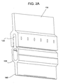
- Figure 2 including Figures 2A and 2B , illustrates in perspective the frangible joint of Figure 1 having the shock attenuation features formed integrally therein in accordance with the embodiment of the invention
- FIG. 3 illustrates a frangible joint having shock attenuation features formed integrally therein in accordance with another embodiment of the invention.
- Figure 4 illustrates a frangible joint having shock attenuation features formed integrally therein in accordance with yet another embodiment of the invention.
- approximating language may be applied to modify any quantitative representation that may vary without resulting in a change in the basic function to which it is related. Accordingly, a value modified by a term or terms, such as “about” and “substantially,” may not to be limited to the precise value specified, in some cases. In at least some instances, the approximating language may correspond to the precision of an instrument for measuring the value.
- a frangible joint structure includes shock attenuation features formed as an integral part of the joint structure. Shock attenuation is achieved through use of, for example, slots or grooves that are machined directly, or otherwise formed integrally, into the frangible joint structure. Adequate shock attenuation is achieved solely by the features machined or otherwise formed in the frangible joint together with the typical assembly of the frangible joint into various structures (e.g., as a payload separator for rockets, missiles, satellites, etc.), without the need for additional hardware components and thus without the need for assembly of the frangible joint shock attenuation device.
- shock attenuation is achieved through use of, for example, slots or grooves that are machined directly, or otherwise formed integrally, into the frangible joint structure. Adequate shock attenuation is achieved solely by the features machined or otherwise formed in the frangible joint together with the typical assembly of the frangible joint into various structures (e.g., as a payload separator for rockets, missiles,
- a frangible joint 100 having a plurality of shock attenuation features formed integrally therein in accordance with an embodiment of the invention.
- the frangible joint typically comprises aluminum or other suitable materials, while the shock attenuation features comprise a plurality of slots or grooves 110 machined or otherwise formed in the aluminum frangible joint 100.
- one end 120 of the frangible joint 100 may connect to a structure 130 to be isolated from pyroshock from another component (not shown) connected to the other end 140 of the frangible joint 100.
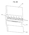
- the partial cutaway view of Figure 2B illustrates the slots or grooves 110 that comprise the shock attenuation features that are formed directly in the frangible joint 100.
- the pattern of slots 110 can be formed on one or both sides of frangible joint 100.
- the number of rows of slots 110, the number of slots 110 in each row, and the geometry of the slots 110 are tailored to the desired amount of shock attenuation to be achieved.
- the shock attenuation features comprise a plurality of slots or grooves 310 that are curved, wherein some of the slots or grooves 310 have a convex curve and other slots or grooves 310 have a concave curve.
- Figure 4 illustrates a frangible joint 400 having shock attenuation features formed integrally therein in accordance with yet another embodiment of the invention.
- the shock attenuation features comprise a plurality of slots or grooves 410 that are angled.
- the design of the slots or grooves that comprise the shock attenuation features of the invention can be applied to any of the present frangible joint styles (e.g., hollow form extrusion, tongue-in-groove, etc.).
- the shock attenuation features may be machined directly into frangible joint or formed in some other manner, depending in part upon the material that comprises the frangible joint.
Landscapes
- Engineering & Computer Science (AREA)
- Mechanical Engineering (AREA)
- General Engineering & Computer Science (AREA)
- Remote Sensing (AREA)
- Aviation & Aerospace Engineering (AREA)
- Vibration Dampers (AREA)
- Filling Or Discharging Of Gas Storage Vessels (AREA)
Abstract
A frangible joint structure (100,300,400) includes shock attenuation features (110,310,410) formed as an integral part of the joint structure. Shock attenuation is achieved through use of, for example, slots or grooves (110,310,410) that are machined directly, or otherwise formed integrally, into the frangible joint structure (100,300,400). Adequate shock attenuation is achieved solely by the features machined or otherwise formed in the frangible joint together with the typical assembly of the frangible joint into various structures (e.g., as a payload separator for rockets, missiles, satellites, etc.), without the need for additional hardware components and thus without the need for assembly of the frangible joint shock attenuation device.
Description
- This application claims the benefit of
U.S. Provisional Application Serial No. 61/082,689 - The present invention relates in general to a device that provides for the attenuation of shock, and in particular, to a frangible joint having shock attenuation features formed integrally therein.
- Frangible joints of various design configurations are common, for example, those comprising a hollow form extrusion. Also, various devices for shock attenuation are also known, for example, those that include a cylindrical flexible structure having one or more viscoelastic members secured to an outer surface of the cylindrical structure. In this known arrangement, the cylindrical structure has machined features to tune stiffness and shock transmissibility therethrough. The cylindrical structure may be used, for example, as a shock isolation mount between a spacecraft and a launch vehicle.
- However, this arrangement suffers from the drawback that additional hardware components beyond the cylindrical structure (i.e., the viscoelastic members along with corresponding outer rigid constraining members secured to the outer surface of each viscoelastic member) are required to achieve the desired amount of shock attenuation between the launch vehicle and the spacecraft.
- What is needed is a frangible joint that includes shock attenuation features formed integrally therein, thereby eliminating the need for additional components to achieve the desired amount of shock attenuation.
- According to an embodiment of the invention, a frangible joint structure includes shock attenuation features formed as an integral part of the joint structure. Shock attenuation is achieved through use of, for example, slots or grooves that are machined directly, or otherwise formed integrally, into the frangible joint structure. Adequate shock attenuation is achieved solely by the features machined or otherwise formed in the frangible joint together with the typical assembly of the frangible joint into various structures (e.g., as a payload separator for rockets, missiles, satellites, etc.), without the need for additional hardware components and thus without the need for assembly of the frangible joint shock attenuation device.
- The various embodiments of the present invention can be understood with reference to the following drawings. The components are not necessarily to scale. Also, in the drawings, like reference numerals designate corresponding parts throughout the several views.
-
Figure 1 illustrates a frangible joint having shock attenuation features formed integrally therein in accordance with an embodiment of the invention; -
Figure 2 , includingFigures 2A and2B , illustrates in perspective the frangible joint ofFigure 1 having the shock attenuation features formed integrally therein in accordance with the embodiment of the invention; -
Figure 3 illustrates a frangible joint having shock attenuation features formed integrally therein in accordance with another embodiment of the invention; and -
Figure 4 illustrates a frangible joint having shock attenuation features formed integrally therein in accordance with yet another embodiment of the invention. - The present invention is more particularly described in the following description and examples that are intended to be illustrative only since numerous modifications and variations therein will be apparent to those skilled in the art. As used in the specification and in the claims, the singular form "a," "an," and "the" may include plural referents unless the context clearly dictates otherwise. Also, as used in the specification and in the claims, the term "comprising" may include the embodiments "consisting of" and "consisting essentially of." Furthermore, all ranges disclosed herein are inclusive of the endpoints and are independently combinable.
- As used herein, approximating language may be applied to modify any quantitative representation that may vary without resulting in a change in the basic function to which it is related. Accordingly, a value modified by a term or terms, such as "about" and "substantially," may not to be limited to the precise value specified, in some cases. In at least some instances, the approximating language may correspond to the precision of an instrument for measuring the value.
- In an embodiment of the invention, a frangible joint structure includes shock attenuation features formed as an integral part of the joint structure. Shock attenuation is achieved through use of, for example, slots or grooves that are machined directly, or otherwise formed integrally, into the frangible joint structure. Adequate shock attenuation is achieved solely by the features machined or otherwise formed in the frangible joint together with the typical assembly of the frangible joint into various structures (e.g., as a payload separator for rockets, missiles, satellites, etc.), without the need for additional hardware components and thus without the need for assembly of the frangible joint shock attenuation device.
- The foregoing and other features of various disclosed embodiments of the invention will be more readily apparent from the following detailed description and drawings of the illustrative embodiments of the invention wherein like reference numbers refer to similar elements.
- Referring to
Figure 1 , there illustrated is afrangible joint 100 having a plurality of shock attenuation features formed integrally therein in accordance with an embodiment of the invention. In this embodiment, the frangible joint typically comprises aluminum or other suitable materials, while the shock attenuation features comprise a plurality of slots orgrooves 110 machined or otherwise formed in the aluminumfrangible joint 100. Referring also toFigure 2 , includingFigures 2A and2B , oneend 120 of thefrangible joint 100 may connect to astructure 130 to be isolated from pyroshock from another component (not shown) connected to theother end 140 of thefrangible joint 100. The partial cutaway view ofFigure 2B illustrates the slots orgrooves 110 that comprise the shock attenuation features that are formed directly in thefrangible joint 100. The pattern ofslots 110 can be formed on one or both sides offrangible joint 100. The number of rows ofslots 110, the number ofslots 110 in each row, and the geometry of theslots 110 are tailored to the desired amount of shock attenuation to be achieved. - Regarding the geometry of the
slots 110, straight, angled and curved slots will have different effects on the amount of shock attenuation achieved by thefrangible joint 100 and on the joint load capacity (longitudinal, shear and bending). Thus, referring toFigure 3 , there illustrated is afrangible joint 300 having shock attenuation features formed integrally therein in accordance with another embodiment of the invention. In this embodiment, the shock attenuation features comprise a plurality of slots orgrooves 310 that are curved, wherein some of the slots orgrooves 310 have a convex curve and other slots orgrooves 310 have a concave curve.Figure 4 illustrates afrangible joint 400 having shock attenuation features formed integrally therein in accordance with yet another embodiment of the invention. In this embodiment, the shock attenuation features comprise a plurality of slots orgrooves 410 that are angled. - The design of the slots or grooves that comprise the shock attenuation features of the invention can be applied to any of the present frangible joint styles (e.g., hollow form extrusion, tongue-in-groove, etc.). The shock attenuation features may be machined directly into frangible joint or formed in some other manner, depending in part upon the material that comprises the frangible joint. An advantage of the frangible joint of the various embodiments of the invention is that no additional components are required - thus, no assembly steps are required.
- This written description uses examples to disclose the invention, including the best mode, and also to enable any person skilled in the art to make and use the invention. The patentable scope of the invention is defined by the claims, and may include other examples that occur to those skilled in the art. Such other examples are intended to be within the scope of the claims if they have structural elements that do not differ from the literal language of the claims, or if they include equivalent structural elements with insubstantial differences from the literal languages of the claims. All citations referred herein are expressly incorporated herein by reference.
Claims (20)
- A frangible joint, comprising:at least one shock attenuation feature formed directly into the frangible joint.
- The frangible joint of claim 1, wherein the at least one shock attenuation feature is formed through an entire thickness of the frangible joint.
- The frangible joint of claim 1, wherein the at least one shock attenuation feature formed directly into the frangible joint comprises a slot.
- The frangible joint of claim 1, wherein the at least one shock attenuation feature formed directly into the frangible joint comprises a groove.
- The frangible joint of claim 1, wherein the at least one shock attenuation feature formed directly into the frangible joint comprises one of a slot or groove, wherein the slot or groove is straight.
- The frangible joint of claim 1, wherein the at least one shock attenuation feature formed directly into the frangible joint comprises one of a slot or groove, wherein the slot or groove is curved.
- The frangible joint of claim 6, wherein the curved groove has one of a convex curve or a concave curve.
- The frangible joint of claim 1, wherein the at least one shock attenuation feature formed directly into the frangible joint comprises one of a slot or groove, wherein the slot or groove is angled.
- A frangible joint, comprising:at least one shock attenuation feature formed integrally within the frangible joint, wherein the at least one shock attenuation feature attenuates shock based on at least one of a shape of the shock attenuation feature or a geometry of the shock attenuation feature.
- The frangible joint of claim 9, wherein the at least one shock attenuation feature formed integrally within the frangible joint comprises a slot.
- The frangible joint of claim 9, wherein the at least one shock attenuation feature formed integrally within the frangible joint comprises a groove.
- The frangible joint of claim 9, wherein the at least one shock attenuation feature formed integrally within the frangible joint comprises one of a slot or groove, wherein the slot or groove is straight.
- The frangible joint of claim 9, wherein the at least one shock attenuation feature formed integrally within the frangible joint comprises one of a slot or groove, wherein the slot or groove is curved.
- The frangible joint of claim 9, wherein the at least one shock attenuation feature formed integrally within the frangible joint comprises one of a slot or groove, wherein the slot or groove is angled.
- The frangible joint of claim 9, wherein the at least one shock attenuation feature is formed through an entire thickness of the frangible joint.
- The frangible joint of claim 9, wherein the at least one shock attenuation feature formed directly into the frangible joint comprises a curved groove, wherein the curved groove has one of a convex or a concave curve.
- A frangible joint, comprising:at least one shock attenuation feature formed in the frangible joint, wherein the frangible joint is connected with at least one structure.
- The frangible joint of claim 17, wherein the at least one shock attenuation feature comprises a slot.
- The frangible joint of claim 17, wherein the at least one shock attenuation feature comprises a groove.
- The frangible joint of claim 17, wherein the at least one shock attenuation feature comprises a pattern of slots or grooves.
Applications Claiming Priority (1)
| Application Number | Priority Date | Filing Date | Title |
|---|---|---|---|
| US8268908P | 2008-07-22 | 2008-07-22 |
Publications (1)
| Publication Number | Publication Date |
|---|---|
| EP2147828A1 true EP2147828A1 (en) | 2010-01-27 |
Family
ID=41100539
Family Applications (1)
| Application Number | Title | Priority Date | Filing Date |
|---|---|---|---|
| EP09166087A Withdrawn EP2147828A1 (en) | 2008-07-22 | 2009-07-22 | Low shock frangible joint |
Country Status (4)
| Country | Link |
|---|---|
| US (1) | US20120061520A1 (en) |
| EP (1) | EP2147828A1 (en) |
| JP (1) | JP2010030587A (en) |
| IL (1) | IL199895A0 (en) |
Cited By (1)
| Publication number | Priority date | Publication date | Assignee | Title |
|---|---|---|---|---|
| WO2013083898A1 (en) * | 2011-12-07 | 2013-06-13 | Astrium Sas | Pyrotechnique rupture method and components for implementing it |
Families Citing this family (3)
| Publication number | Priority date | Publication date | Assignee | Title |
|---|---|---|---|---|
| US8727654B2 (en) | 2008-07-22 | 2014-05-20 | Ensign-Bickford Aerospace & Defense Company | Separation system with shock attenuation |
| US10479473B2 (en) | 2016-06-30 | 2019-11-19 | Insitu, Inc | Omnidirectional frangible joint |
| US11572203B2 (en) * | 2021-07-08 | 2023-02-07 | Saab Bofors Dynamics Switzerland Ltd. | Release mechanism |
Citations (4)
| Publication number | Priority date | Publication date | Assignee | Title |
|---|---|---|---|---|
| US5969287A (en) * | 1997-12-16 | 1999-10-19 | Lockheed Martin Corporation | Separation system |
| FR2888925A1 (en) * | 2005-07-22 | 2007-01-26 | Eads Space Transp Sas Soc Par | PIECE WITH DETONATING PYROTECHNIC RUPTURE |
| US20070084688A1 (en) * | 2005-10-19 | 2007-04-19 | Gilleo Kevin L | Collapsible member |
| CA2560370A1 (en) * | 2006-09-15 | 2008-03-15 | George Ming Yat Kwok | Collision impact force mitigating device |
Family Cites Families (15)
| Publication number | Priority date | Publication date | Assignee | Title |
|---|---|---|---|---|
| US3362290A (en) * | 1965-04-13 | 1968-01-09 | Mc Donnell Douglas Corp | Non-contaminating thrusting separation system |
| US3319520A (en) * | 1965-06-23 | 1967-05-16 | Trw Inc | High speed low shock separation system |
| US3698281A (en) * | 1970-02-27 | 1972-10-17 | Lockheed Aircraft Corp | Explosive system |
| US4106875A (en) * | 1977-09-23 | 1978-08-15 | The United States Of America As Represented By The Secretary Of The Navy | Explosively-separated tongue and groove joint |
| US4685376A (en) * | 1985-06-24 | 1987-08-11 | Mcdonnell Douglas Corporation | Separation system |
| US5109749A (en) * | 1988-10-25 | 1992-05-05 | Oea, Inc. | Explosively actuated separable structure |
| FR2665951B1 (en) * | 1990-08-20 | 1992-11-13 | Aerospatiale | BREAKABLE CONNECTION SYSTEM FOR SEPARATING PARTS BY MEANS OF A DETONATING LOAD. |
| US5390606A (en) * | 1992-11-02 | 1995-02-21 | Orbital Sciences Corporation | Frangible joint separation system |
| US5372071A (en) * | 1993-07-13 | 1994-12-13 | Tracor, Inc. | Thrusting separation system |
| US5898123A (en) * | 1997-05-01 | 1999-04-27 | The Ensign-Bickford Company | Sealing device and a method for assembly thereof |
| US6125762A (en) * | 1997-07-03 | 2000-10-03 | The Ensign-Bickford Company | Flat-form separation devices |
| JP2001171600A (en) * | 1999-12-14 | 2001-06-26 | Natl Space Development Agency Of Japan | Deployment release retention bracket |
| US6202961B1 (en) * | 2000-03-21 | 2001-03-20 | Csa Engineering | Passive, multi-axis, highly damped, shock isolation mounts for spacecraft |
| US20030034597A1 (en) * | 2001-08-20 | 2003-02-20 | Wallach Andrew R. | Shock filtering apparatus |
| FR2861691B1 (en) * | 2003-11-05 | 2006-01-27 | Eads Space Transportation Sa | COMPOSITE STRUCTURAL PIECE WITH DETONATING PYROTECHNIC RUPTURE. |
-
2009
- 2009-07-13 US US12/501,577 patent/US20120061520A1/en not_active Abandoned
- 2009-07-16 IL IL199895A patent/IL199895A0/en unknown
- 2009-07-21 JP JP2009169842A patent/JP2010030587A/en active Pending
- 2009-07-22 EP EP09166087A patent/EP2147828A1/en not_active Withdrawn
Patent Citations (4)
| Publication number | Priority date | Publication date | Assignee | Title |
|---|---|---|---|---|
| US5969287A (en) * | 1997-12-16 | 1999-10-19 | Lockheed Martin Corporation | Separation system |
| FR2888925A1 (en) * | 2005-07-22 | 2007-01-26 | Eads Space Transp Sas Soc Par | PIECE WITH DETONATING PYROTECHNIC RUPTURE |
| US20070084688A1 (en) * | 2005-10-19 | 2007-04-19 | Gilleo Kevin L | Collapsible member |
| CA2560370A1 (en) * | 2006-09-15 | 2008-03-15 | George Ming Yat Kwok | Collision impact force mitigating device |
Cited By (2)
| Publication number | Priority date | Publication date | Assignee | Title |
|---|---|---|---|---|
| WO2013083898A1 (en) * | 2011-12-07 | 2013-06-13 | Astrium Sas | Pyrotechnique rupture method and components for implementing it |
| FR2983925A1 (en) * | 2011-12-07 | 2013-06-14 | Astrium Sas | PYROTECHNIC RUPTURE PROCESS AND PIECE FOR ITS IMPLEMENTATION |
Also Published As
| Publication number | Publication date |
|---|---|
| US20120061520A1 (en) | 2012-03-15 |
| IL199895A0 (en) | 2010-04-29 |
| JP2010030587A (en) | 2010-02-12 |
Similar Documents
| Publication | Publication Date | Title |
|---|---|---|
| US8727654B2 (en) | Separation system with shock attenuation | |
| EP2197741B1 (en) | Helicopter aircraft vehicle rotor damper | |
| US8695473B2 (en) | Overextrusion of silicone rubber charge holder on metal wire rope | |
| EP1268277B1 (en) | Passive, multi-axis, highly damped, shock isolation mounts | |
| EP2147828A1 (en) | Low shock frangible joint | |
| EP2628682B1 (en) | Space shuttle damping and isolating device | |
| DK1994324T3 (en) | Højpassivt subdued vibrationsisoleringsbeslag low profile and multiple axes | |
| WO2012095067A1 (en) | Turbomachine blade having a tuning element | |
| CN102597548B (en) | There is the joint of the bulb be fixed on axle journal | |
| US20130236234A1 (en) | Dual tube frangible joint | |
| US20040131294A1 (en) | Double-row ball bearings and double-row ball bearing preload application method | |
| EP3165870B1 (en) | Folding wing for a missile and a missile having at least one folding wing arranged thereon | |
| WO1999000299A1 (en) | Passive lateral vibration isolation system for a spacecraft launch vehicle | |
| DE102017129060A1 (en) | Integrated support structure for an aircraft engine and its accessory components | |
| EP2876327A2 (en) | Isolators having nested flexure devices and methods for the production thereof | |
| EP3312097B1 (en) | Light passive attenuator for spacecraft | |
| EP3295052B1 (en) | Damping devices, systems and methods for hollow shafts, struts, and beams with bending modes | |
| US8727079B2 (en) | Structural member with clamping pressure mechanism | |
| TW201828532A (en) | Dish antenna and method for manufacturing bracket thereof and dish stand assembly thereof | |
| EP3885603B1 (en) | Flexure isolator and method of compliant isolation | |
| US20150246854A1 (en) | Fully-redundant frangible separation system | |
| WO2019175114A1 (en) | Camera system | |
| EP2325086A1 (en) | Zero-shock separation system | |
| EP2450592A2 (en) | Dampening device | |
| EP1197669A1 (en) | Insert intended for the fixing of a device and methods for realization and fixing of this insert |
Legal Events
| Date | Code | Title | Description |
|---|---|---|---|
| PUAI | Public reference made under article 153(3) epc to a published international application that has entered the european phase |
Free format text: ORIGINAL CODE: 0009012 |
|
| AK | Designated contracting states |
Kind code of ref document: A1 Designated state(s): AT BE BG CH CY CZ DE DK EE ES FI FR GB GR HR HU IE IS IT LI LT LU LV MC MK MT NL NO PL PT RO SE SI SK SM TR |
|
| AX | Request for extension of the european patent |
Extension state: AL BA RS |
|
| 17P | Request for examination filed |
Effective date: 20100723 |
|
| 17Q | First examination report despatched |
Effective date: 20100813 |
|
| STAA | Information on the status of an ep patent application or granted ep patent |
Free format text: STATUS: THE APPLICATION IS DEEMED TO BE WITHDRAWN |
|
| 18D | Application deemed to be withdrawn |
Effective date: 20130403 |