EP2147791A1 - Method of manufacturing a droplet jetting device and an ink jet device - Google Patents
Method of manufacturing a droplet jetting device and an ink jet device Download PDFInfo
- Publication number
- EP2147791A1 EP2147791A1 EP08160905A EP08160905A EP2147791A1 EP 2147791 A1 EP2147791 A1 EP 2147791A1 EP 08160905 A EP08160905 A EP 08160905A EP 08160905 A EP08160905 A EP 08160905A EP 2147791 A1 EP2147791 A1 EP 2147791A1
- Authority
- EP
- European Patent Office
- Prior art keywords
- nozzle plate
- mold
- substrate
- nozzle
- sacrificial layer
- Prior art date
- Legal status (The legal status is an assumption and is not a legal conclusion. Google has not performed a legal analysis and makes no representation as to the accuracy of the status listed.)
- Ceased
Links
- 238000004519 manufacturing process Methods 0.000 title claims abstract description 12
- 239000000758 substrate Substances 0.000 claims abstract description 41
- 239000000463 material Substances 0.000 claims abstract description 27
- 238000005530 etching Methods 0.000 claims abstract description 19
- 238000007493 shaping process Methods 0.000 claims abstract description 3
- 238000000034 method Methods 0.000 claims description 33
- 239000011521 glass Substances 0.000 claims description 3
- 238000004528 spin coating Methods 0.000 claims 1
- 239000010410 layer Substances 0.000 description 31
- 239000011241 protective layer Substances 0.000 description 5
- 239000011347 resin Substances 0.000 description 5
- 229920005989 resin Polymers 0.000 description 5
- XUIMIQQOPSSXEZ-UHFFFAOYSA-N Silicon Chemical compound [Si] XUIMIQQOPSSXEZ-UHFFFAOYSA-N 0.000 description 3
- 238000001312 dry etching Methods 0.000 description 3
- 230000000873 masking effect Effects 0.000 description 3
- 229910052710 silicon Inorganic materials 0.000 description 3
- 239000010703 silicon Substances 0.000 description 3
- 238000001039 wet etching Methods 0.000 description 3
- 229910021417 amorphous silicon Inorganic materials 0.000 description 2
- 229910021420 polycrystalline silicon Inorganic materials 0.000 description 2
- 229920000642 polymer Polymers 0.000 description 2
- 238000009736 wetting Methods 0.000 description 2
- 230000004323 axial length Effects 0.000 description 1
- 230000000295 complement effect Effects 0.000 description 1
- 230000007423 decrease Effects 0.000 description 1
- 230000001419 dependent effect Effects 0.000 description 1
- 235000012489 doughnuts Nutrition 0.000 description 1
- 238000005553 drilling Methods 0.000 description 1
- 230000000694 effects Effects 0.000 description 1
- 239000012212 insulator Substances 0.000 description 1
- 230000004048 modification Effects 0.000 description 1
- 238000012986 modification Methods 0.000 description 1
- 238000000465 moulding Methods 0.000 description 1
- 150000004767 nitrides Chemical class 0.000 description 1
- 238000000206 photolithography Methods 0.000 description 1
Images

Classifications
-
- B—PERFORMING OPERATIONS; TRANSPORTING
- B41—PRINTING; LINING MACHINES; TYPEWRITERS; STAMPS
- B41J—TYPEWRITERS; SELECTIVE PRINTING MECHANISMS, i.e. MECHANISMS PRINTING OTHERWISE THAN FROM A FORME; CORRECTION OF TYPOGRAPHICAL ERRORS
- B41J2/00—Typewriters or selective printing mechanisms characterised by the printing or marking process for which they are designed
- B41J2/005—Typewriters or selective printing mechanisms characterised by the printing or marking process for which they are designed characterised by bringing liquid or particles selectively into contact with a printing material
- B41J2/01—Ink jet
- B41J2/135—Nozzles
- B41J2/16—Production of nozzles
- B41J2/162—Manufacturing of the nozzle plates
-
- B—PERFORMING OPERATIONS; TRANSPORTING
- B41—PRINTING; LINING MACHINES; TYPEWRITERS; STAMPS
- B41J—TYPEWRITERS; SELECTIVE PRINTING MECHANISMS, i.e. MECHANISMS PRINTING OTHERWISE THAN FROM A FORME; CORRECTION OF TYPOGRAPHICAL ERRORS
- B41J2/00—Typewriters or selective printing mechanisms characterised by the printing or marking process for which they are designed
- B41J2/005—Typewriters or selective printing mechanisms characterised by the printing or marking process for which they are designed characterised by bringing liquid or particles selectively into contact with a printing material
- B41J2/01—Ink jet
- B41J2/135—Nozzles
- B41J2/14—Structure thereof only for on-demand ink jet heads
- B41J2/1433—Structure of nozzle plates
-
- B—PERFORMING OPERATIONS; TRANSPORTING
- B41—PRINTING; LINING MACHINES; TYPEWRITERS; STAMPS
- B41J—TYPEWRITERS; SELECTIVE PRINTING MECHANISMS, i.e. MECHANISMS PRINTING OTHERWISE THAN FROM A FORME; CORRECTION OF TYPOGRAPHICAL ERRORS
- B41J2/00—Typewriters or selective printing mechanisms characterised by the printing or marking process for which they are designed
- B41J2/005—Typewriters or selective printing mechanisms characterised by the printing or marking process for which they are designed characterised by bringing liquid or particles selectively into contact with a printing material
- B41J2/01—Ink jet
- B41J2/135—Nozzles
- B41J2/16—Production of nozzles
- B41J2/1621—Manufacturing processes
- B41J2/1626—Manufacturing processes etching
- B41J2/1628—Manufacturing processes etching dry etching
-
- B—PERFORMING OPERATIONS; TRANSPORTING
- B41—PRINTING; LINING MACHINES; TYPEWRITERS; STAMPS
- B41J—TYPEWRITERS; SELECTIVE PRINTING MECHANISMS, i.e. MECHANISMS PRINTING OTHERWISE THAN FROM A FORME; CORRECTION OF TYPOGRAPHICAL ERRORS
- B41J2/00—Typewriters or selective printing mechanisms characterised by the printing or marking process for which they are designed
- B41J2/005—Typewriters or selective printing mechanisms characterised by the printing or marking process for which they are designed characterised by bringing liquid or particles selectively into contact with a printing material
- B41J2/01—Ink jet
- B41J2/135—Nozzles
- B41J2/16—Production of nozzles
- B41J2/1621—Manufacturing processes
- B41J2/1626—Manufacturing processes etching
- B41J2/1629—Manufacturing processes etching wet etching
-
- B—PERFORMING OPERATIONS; TRANSPORTING
- B41—PRINTING; LINING MACHINES; TYPEWRITERS; STAMPS
- B41J—TYPEWRITERS; SELECTIVE PRINTING MECHANISMS, i.e. MECHANISMS PRINTING OTHERWISE THAN FROM A FORME; CORRECTION OF TYPOGRAPHICAL ERRORS
- B41J2/00—Typewriters or selective printing mechanisms characterised by the printing or marking process for which they are designed
- B41J2/005—Typewriters or selective printing mechanisms characterised by the printing or marking process for which they are designed characterised by bringing liquid or particles selectively into contact with a printing material
- B41J2/01—Ink jet
- B41J2/135—Nozzles
- B41J2/16—Production of nozzles
- B41J2/1621—Manufacturing processes
- B41J2/1631—Manufacturing processes photolithography
-
- B—PERFORMING OPERATIONS; TRANSPORTING
- B41—PRINTING; LINING MACHINES; TYPEWRITERS; STAMPS
- B41J—TYPEWRITERS; SELECTIVE PRINTING MECHANISMS, i.e. MECHANISMS PRINTING OTHERWISE THAN FROM A FORME; CORRECTION OF TYPOGRAPHICAL ERRORS
- B41J2/00—Typewriters or selective printing mechanisms characterised by the printing or marking process for which they are designed
- B41J2/005—Typewriters or selective printing mechanisms characterised by the printing or marking process for which they are designed characterised by bringing liquid or particles selectively into contact with a printing material
- B41J2/01—Ink jet
- B41J2/135—Nozzles
- B41J2/16—Production of nozzles
- B41J2/1621—Manufacturing processes
- B41J2/1637—Manufacturing processes molding
- B41J2/1639—Manufacturing processes molding sacrificial molding
-
- B—PERFORMING OPERATIONS; TRANSPORTING
- B41—PRINTING; LINING MACHINES; TYPEWRITERS; STAMPS
- B41J—TYPEWRITERS; SELECTIVE PRINTING MECHANISMS, i.e. MECHANISMS PRINTING OTHERWISE THAN FROM A FORME; CORRECTION OF TYPOGRAPHICAL ERRORS
- B41J2/00—Typewriters or selective printing mechanisms characterised by the printing or marking process for which they are designed
- B41J2/005—Typewriters or selective printing mechanisms characterised by the printing or marking process for which they are designed characterised by bringing liquid or particles selectively into contact with a printing material
- B41J2/01—Ink jet
- B41J2/135—Nozzles
- B41J2/16—Production of nozzles
- B41J2/1621—Manufacturing processes
- B41J2/164—Manufacturing processes thin film formation
- B41J2/1645—Manufacturing processes thin film formation thin film formation by spincoating
-
- B—PERFORMING OPERATIONS; TRANSPORTING
- B41—PRINTING; LINING MACHINES; TYPEWRITERS; STAMPS
- B41J—TYPEWRITERS; SELECTIVE PRINTING MECHANISMS, i.e. MECHANISMS PRINTING OTHERWISE THAN FROM A FORME; CORRECTION OF TYPOGRAPHICAL ERRORS
- B41J2/00—Typewriters or selective printing mechanisms characterised by the printing or marking process for which they are designed
- B41J2/005—Typewriters or selective printing mechanisms characterised by the printing or marking process for which they are designed characterised by bringing liquid or particles selectively into contact with a printing material
- B41J2/01—Ink jet
- B41J2/135—Nozzles
- B41J2/14—Structure thereof only for on-demand ink jet heads
- B41J2002/14475—Structure thereof only for on-demand ink jet heads characterised by nozzle shapes or number of orifices per chamber
Definitions
- Droplet jetting devices are typically employed in ink jet printheads and comprise an array of nozzles through which ink droplets are to be jetted out. Each nozzle communicates with an ink channel or chamber that comprises an actuator, e. g. a piezoelectric or thermal actuator, for creating a pressure pulse in the ink contained in the chamber, so that a droplet is expelled through the nozzle.
- an actuator e. g. a piezoelectric or thermal actuator
- the ink chambers or ink channels are formed in a substrate and are open to one surface of the substrate through a feedthrough.
- the nozzles are formed by etching or drilling holes into a separate nozzle plate which is then bonded to the substrate. In this bonding step, it is necessary to carefully align the nozzles with the corresponding feedthroughs in the substrate.
- the nozzles generally have a straight cylindrical shape, although fluid-mechanical considerations suggest that smoother nozzle shapes with a non-constant diameter of the nozzle hole provide better results in terms of stability and uniformity of droplet generation.
- US 2004/051757 A1 describes a process for forming convergent/divergent nozzle shapes.
- an auxiliary substrate is masked with a pattern of isolated islands, and then the substrate material around the islands is isotropically etched away, which leaves a tapering spike under each island. These spikes then serve as negative molds for the nozzle holes.
- a layer of a photocurable resin is applied onto the substrate so as to bury the spikes therein.
- the areas above each spike are masked again and the resin around the masks is cured by light exposure.
- the non-cured resin is removed, so that a hole penetrates the resin layer above each spike.
- the resin layer is removed from the auxiliary substrate and can then be used as a nozzle plate with nozzles having a non-constant diameter.
- the method according to the invention comprises the steps of:
- the isotropic etching process has the effect that the edges of the nozzle holes on the entry side facing the feedthrough are rounded off and assume a shape similar to a mouth of a trumpet. Nozzles with this shape have been found to produce very stable and well-defined ink jets, because the ink is allowed to flow more smoothly into the nozzle holes. In particular, this nozzle shape reduces the creation of air bubbles in the nozzles, which could easily cause nozzle failure.
- the nozzle plate can be formed directly on the surface of the substrate in which the feedthroughs and possibly the entire ink chambers are formed, so that no complicated aligning and bonding steps are required.
- the positions of the individual nozzles can be determined very precisely by employing photolithographic techniques for masking and etching, and similar photolithographic techniques can be employed for forming the feedthroughs in the substrate, the position of the nozzle holes relative to the feedthroughs can be determined with high accuracy.
- the invention also relates to an ink jet device that may be obtained by the method according to the invention and wherein the edges of the nozzle holes on the side facing the feedthrough are rounded in a trumpet shape.
- the sacrificial layer is etched away until only the spike-shaped molds for the nozzle holes remain.
- the amount of the sacrificial material to be etched away can be reduced by employing a masking pattern in which each island is surrounded only by an annular gap. Then, isotropic etching will produce a cavity that has the shape of one half of a torus or donut with the spike in the center.
- the substrate with the sacrificial layer thereon may be formed by applying a sacrificial layer of a polymer, poly-silicon, amorphous silicon or the like on a silicon wafer.
- a sacrificial layer of a polymer, poly-silicon, amorphous silicon or the like on a silicon wafer.
- an SOI (silicon-on-insulator) wafer may be employed, wherein the active layer serves as the sacrificial layer.
- the thickness of the plate material may optionally be selected larger than the height of the mold spikes, so that the molds are completely buried in the nozzle plate material. Then, by grinding of etching the surface of the nozzle plate, the tips of the mold can be exposed again, and the length of the nozzle holes can in this way be controlled with high accuracy.
- a part of the feedthrough in the substrate and other structures connected thereto can be formed in the substrate, e.g., by directional dry etching, at any stage prior to the final process step in which the molds for the nozzle holes are etched away.
- Fig. 1 is a cross-sectional view of a part of a substrate 10, e.g. a silicon wafer.
- the top surface of the substrate 10 may be covered by a protective layer 12, which may be an oxide layer, a nitride layer or the like.
- Another protective layer 14 which may serve as an etch stop in a later stage of the process may be formed on the bottom surface of the substrate 10.
- a sacrificial layer 16 is formed on the surface of the substrate 10 which is the bottom surface in Fig. 2 .
- the drawings show the ink jet device in its various production stages in an orientation where the droplet discharge direction of the completed device would be downward.
- the wafer 10 may have a different orientation during the various production steps.
- the sacrificial layer 16 may for example be a layer of a polymer, poly-silicon, amorphous silicon or the like. It should preferably be a material that can more easily be etched by isotropic wet etching than the silicon wafer 10 or at least the protective layer 14 thereof.
- an SOI wafer may be used instead of the substrate 10, and the production process would then start with the stage shown in Fig. 2 , wherein the protective layer 14 would be formed by a BOX (buried oxide) layer of the SOI wafer, and the sacrificial layer 16 would be an active layer of that wafer.
- the protective layer 14 would be formed by a BOX (buried oxide) layer of the SOI wafer, and the sacrificial layer 16 would be an active layer of that wafer.
- an etch mask has been formed on the bottom face of the sacrificial layer 16.
- the mask is formed by an isolated patch or island 18 of a masking material and is applied and patterned with techniques known from photolithography.
- a major part of the sacrificial layer 16 is etched away by isotropic wet etching, and only a spike-shaped mold 20 is left above the central area of the island 18.
- the mold 20 can later be used for molding a nozzle hole, and, consequently, its shape will be the negative or complement of the nozzle hole.
- the flanks of the mold 20 are rounded, and the diameter of the mold decreases from the top to the bottom, i.e. in droplet discharge direction.
- This shape of the mold 20 is brought about by the isotropic etching process in which the etch front propagates with essentially uniform velocity in all directions and therefore undercuts the edge of the island 18.
- the island 18 has a circular shape, so that the nozzle hole will have rotational symmetry and will have the three-dimensional shape of the bell of a trumpet.
- the portion of the substrate 10 shown in the drawings has the size of an individual ink jet device, i.e. a single set of a nozzle, an ink chamber and an associated actuator.
- the size of the substrate 10 will be significantly larger, and it will include a one- or two-dimensional array of a plurality of such ink jet devices. Consequently, there will be formed an array of a large number of molds 20, one for each nozzle.
- a nozzle plate 22 is formed on the bottom face of the substrate 10, so that the molds 20 are almost completely buried in the material of the nozzle plate 22.
- the mold 20 is etched away in another etching process, so that a nozzle hole 24 is formed in the nozzle plate 22.
- the material of the nozzle plate 22 may be any suitable material that is sufficiently resistant to the etch process and can easily be coated on the surface of the substrate 10.
- glass is a suitable material for the nozzle plate 22, and it may be applied in a spin or reflow process, so that the glass layer will firmly adhere to the substrate 10 and will form a flat nozzle face 26.
- a directional dry etching process is employed for forming, from above, a feedthrough 28 and an ink chamber 30 in the substrate 10.
- the feedthrough could be formed by the ink chamber itself.
- the etching process is continued until the protective layer 14 on the bottom face of the substrate 10 has been etched away, so that the feedthrough 28 will communicate with the nozzle hole 24.
- applying an actuator (not shown) for pressurizing the ink in the ink chamber 30 and/or the feedthrough 28 will complete the ink jet device.
- the nozzle hole 24 is convergent in the (downward) drop discharge direction, and its diameter becomes degressively smaller, so that the sides of the nozzle hole are rounded when seen in a longitudinal section. It has been found that this nozzle shape provides a superior drop generation behavior and suppresses the creation of air bubbles in the nozzle and the wetting of the nozzle face 26.
- FIGs. 8 and 9 illustrate a modified embodiment, wherein a top part of the feedthrough 28 is formed already in a earlier stage of the process, in this case already in the blank substrate 10 before the sacrificial layer is applied (or in the SOI wafer, as the case may be).
- Fig. 9 illustrates the stage where the nozzle plate 22 has been applied and the nozzle hole 24 has been formed by a wet-etching. Then, in a final dry etching step, the feedthrough 28 will be completed.
- Fig. 10 illustrates a modification of the method step that has been shown in Fig. 5 .
- the nozzle plate 22 is applied to a greater thickness, so that the molds 20 are completely buried therein.
- the final nozzle face 26 will be formed by removing, e. g., grinding or etching away, a bottom layer of the nozzle plate 22.
- the substrate 10 may serve as a handle, because the nozzle plate adheres firmly to the substrate.
- the grinding process is continued until the nozzle plate 22 has reached the desired thickness, i.e. the nozzle hole 24 has reached the desired axial length.
- the nozzle plate must be ground at least to such an extent that the bottom end of the mold 20 is exposed to the etching solution.
- Figs. 12-14 illustrate another embodiment of the manufacturing method, wherein a part of the sacrificial layer 16 remains in the completed device.
- the sacrificial layer 16 is covered almost entirely by a mask 32 which is interrupted only by annular gaps that delimit the individual islands 18. Then, isotropic etching results in a cavity 34 that has the shape of one half of a torus and surrounds the mold 20.
- each nozzle has its own nozzle plate formed only by a small ring that surrounds the nozzle hole and is embedded in the sacrificial material.
- the bottom face of the sacrificial layer and parts of the nozzle plate 22 are again covered with a mask 36, as is shown in Fig. 14 .
- This mask will expose only the mold 20 and the surrounding parts of the nozzle plate 22.
- the nozzle hole 24 can be formed by etching away the mold 20.
- the mask 36 is removed and the feedthrough 28 is formed in the same manner as in Fig. 7 or in Fig. 9 .
- an anti-wetting layer (not shown) may be formed on the nozzle face 26. and embedded in a material (16) that is different from the material of the nozzle plate.
Landscapes
- Engineering & Computer Science (AREA)
- Manufacturing & Machinery (AREA)
- Particle Formation And Scattering Control In Inkjet Printers (AREA)
Abstract
A method of manufacturing a droplet jetting device, comprising the steps of:
- providing a substrate (10) with a sacrificial layer on one side thereof;
- applying an island of a mask material on the sacrificial layer and shaping the sacrificial layer into a negative mold (20) for a nozzle hole by isotropic etching around the island;
- forming a nozzle plate (22) by applying material onto the side of the substrate that carries the mold (20), so as to embed the mold in that material;
- etching away the mold (20); and
- removing material of the substrate (10) so as to form therein a feedthrough that communicates with the nozzle hole.
- providing a substrate (10) with a sacrificial layer on one side thereof;
- applying an island of a mask material on the sacrificial layer and shaping the sacrificial layer into a negative mold (20) for a nozzle hole by isotropic etching around the island;
- forming a nozzle plate (22) by applying material onto the side of the substrate that carries the mold (20), so as to embed the mold in that material;
- etching away the mold (20); and
- removing material of the substrate (10) so as to form therein a feedthrough that communicates with the nozzle hole.
Description
- The invention relates to a method of manufacturing a droplet jetting device. Droplet jetting devices are typically employed in ink jet printheads and comprise an array of nozzles through which ink droplets are to be jetted out. Each nozzle communicates with an ink channel or chamber that comprises an actuator, e. g. a piezoelectric or thermal actuator, for creating a pressure pulse in the ink contained in the chamber, so that a droplet is expelled through the nozzle.
- With increasing print resolution, the distance between adjacent nozzles in the nozzle array becomes smaller, and it becomes more difficult to produce the minute structures of the nozzles. In a typical design, the ink chambers or ink channels are formed in a substrate and are open to one surface of the substrate through a feedthrough. The nozzles are formed by etching or drilling holes into a separate nozzle plate which is then bonded to the substrate. In this bonding step, it is necessary to carefully align the nozzles with the corresponding feedthroughs in the substrate.
- The nozzles generally have a straight cylindrical shape, although fluid-mechanical considerations suggest that smoother nozzle shapes with a non-constant diameter of the nozzle hole provide better results in terms of stability and uniformity of droplet generation.
-
US 2004/051757 A1 describes a process for forming convergent/divergent nozzle shapes. In this process, an auxiliary substrate is masked with a pattern of isolated islands, and then the substrate material around the islands is isotropically etched away, which leaves a tapering spike under each island. These spikes then serve as negative molds for the nozzle holes. After the masks have been removed, a layer of a photocurable resin is applied onto the substrate so as to bury the spikes therein. Then, the areas above each spike are masked again and the resin around the masks is cured by light exposure. The non-cured resin is removed, so that a hole penetrates the resin layer above each spike. Finally, the resin layer is removed from the auxiliary substrate and can then be used as a nozzle plate with nozzles having a non-constant diameter. - It is an object of the invention to provide a process for efficiently and reproducibly forming droplet jetting devices in which the nozzle holes have a diameter that varies over the length of the hole.
- In order to achieve this object, the method according to the invention comprises the steps of:
- providing a substrate with a sacrificial layer on one side thereof;
- applying an island of a mask material on the sacrificial layer and shaping the sacrificial layer into a negative mold for a nozzle hole by isotropic etching around the island;
- forming a nozzle plate by applying material onto the side of the substrate that carries the mold, so as to embed the mold in that material;
- etching away the mold; and
- removing material of the substrate so as to form therein a feedthrough that communicates with the nozzle hole.
- The isotropic etching process has the effect that the edges of the nozzle holes on the entry side facing the feedthrough are rounded off and assume a shape similar to a mouth of a trumpet. Nozzles with this shape have been found to produce very stable and well-defined ink jets, because the ink is allowed to flow more smoothly into the nozzle holes. In particular, this nozzle shape reduces the creation of air bubbles in the nozzles, which could easily cause nozzle failure.
- It is an other particular advantage of the invention that the nozzle plate can be formed directly on the surface of the substrate in which the feedthroughs and possibly the entire ink chambers are formed, so that no complicated aligning and bonding steps are required.
- Since the positions of the individual nozzles can be determined very precisely by employing photolithographic techniques for masking and etching, and similar photolithographic techniques can be employed for forming the feedthroughs in the substrate, the position of the nozzle holes relative to the feedthroughs can be determined with high accuracy.
- The invention also relates to an ink jet device that may be obtained by the method according to the invention and wherein the edges of the nozzle holes on the side facing the feedthrough are rounded in a trumpet shape.
- More specific optional features of the invention are indicated in the dependent claims.
- In one embodiment of the invention, the sacrificial layer is etched away until only the spike-shaped molds for the nozzle holes remain. In a modified embodiment, the amount of the sacrificial material to be etched away can be reduced by employing a masking pattern in which each island is surrounded only by an annular gap. Then, isotropic etching will produce a cavity that has the shape of one half of a torus or donut with the spike in the center.
- The substrate with the sacrificial layer thereon may be formed by applying a sacrificial layer of a polymer, poly-silicon, amorphous silicon or the like on a silicon wafer. As an alternative, an SOI (silicon-on-insulator) wafer may be employed, wherein the active layer serves as the sacrificial layer.
- When forming the electrode plate, the thickness of the plate material may optionally be selected larger than the height of the mold spikes, so that the molds are completely buried in the nozzle plate material. Then, by grinding of etching the surface of the nozzle plate, the tips of the mold can be exposed again, and the length of the nozzle holes can in this way be controlled with high accuracy.
- A part of the feedthrough in the substrate and other structures connected thereto, e.g. an ink chamber, can be formed in the substrate, e.g., by directional dry etching, at any stage prior to the final process step in which the molds for the nozzle holes are etched away.
- Preferred embodiment of the invention will now be explained in conjunction with the drawings, wherein:
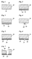
- Figs. 1 to 7
- are cross-sectional views of a part of an ink jet device in a number of subsequent production stages;
- Figs. 8 and 9
- show production stages corresponding to those in
Figs. 1 and 6 , for a modified embodiment; - Figs. 10 and 11
- illustrate production stages corresponding to those in
Figs. 5 and 6 , for yet another embodiment of the invention; and - Figs. 12 to 14
- illustrate production steps corresponding to those in
Figs. 4 to 7 for yet another embodiment of the invention. -
Fig. 1 is a cross-sectional view of a part of asubstrate 10, e.g. a silicon wafer. In this embodiment, the top surface of thesubstrate 10 may be covered by aprotective layer 12, which may be an oxide layer, a nitride layer or the like. Anotherprotective layer 14 which may serve as an etch stop in a later stage of the process may be formed on the bottom surface of thesubstrate 10. - In
Fig. 2 , asacrificial layer 16 is formed on the surface of thesubstrate 10 which is the bottom surface inFig. 2 . It should be noted that the drawings show the ink jet device in its various production stages in an orientation where the droplet discharge direction of the completed device would be downward. Of course, thewafer 10 may have a different orientation during the various production steps. - The
sacrificial layer 16 may for example be a layer of a polymer, poly-silicon, amorphous silicon or the like. It should preferably be a material that can more easily be etched by isotropic wet etching than thesilicon wafer 10 or at least theprotective layer 14 thereof. - In a modified embodiment, an SOI wafer may be used instead of the
substrate 10, and the production process would then start with the stage shown inFig. 2 , wherein theprotective layer 14 would be formed by a BOX (buried oxide) layer of the SOI wafer, and thesacrificial layer 16 would be an active layer of that wafer. - In
Fig. 3 , an etch mask has been formed on the bottom face of thesacrificial layer 16. The mask is formed by an isolated patch orisland 18 of a masking material and is applied and patterned with techniques known from photolithography. - Then, as is shown in
Fig. 4 , a major part of thesacrificial layer 16 is etched away by isotropic wet etching, and only a spike-shaped mold 20 is left above the central area of theisland 18. Themold 20 can later be used for molding a nozzle hole, and, consequently, its shape will be the negative or complement of the nozzle hole. As can be seen inFig. 4 , the flanks of themold 20 are rounded, and the diameter of the mold decreases from the top to the bottom, i.e. in droplet discharge direction. This shape of themold 20 is brought about by the isotropic etching process in which the etch front propagates with essentially uniform velocity in all directions and therefore undercuts the edge of theisland 18. In a preferred embodiment, theisland 18 has a circular shape, so that the nozzle hole will have rotational symmetry and will have the three-dimensional shape of the bell of a trumpet. - It will be understood that the portion of the
substrate 10 shown in the drawings has the size of an individual ink jet device, i.e. a single set of a nozzle, an ink chamber and an associated actuator. In practice, the size of thesubstrate 10 will be significantly larger, and it will include a one- or two-dimensional array of a plurality of such ink jet devices. Consequently, there will be formed an array of a large number ofmolds 20, one for each nozzle. - In the next step, as is shown in
Fig. 5 , anozzle plate 22 is formed on the bottom face of thesubstrate 10, so that themolds 20 are almost completely buried in the material of thenozzle plate 22. - As is shown in
Fig. 6 , themold 20 is etched away in another etching process, so that anozzle hole 24 is formed in thenozzle plate 22. - The material of the
nozzle plate 22 may be any suitable material that is sufficiently resistant to the etch process and can easily be coated on the surface of thesubstrate 10. For example, glass is a suitable material for thenozzle plate 22, and it may be applied in a spin or reflow process, so that the glass layer will firmly adhere to thesubstrate 10 and will form aflat nozzle face 26. - Finally, as is shown in
Fig. 7 , a directional dry etching process is employed for forming, from above, afeedthrough 28 and anink chamber 30 in thesubstrate 10. In a modified embodiment, the feedthrough could be formed by the ink chamber itself. When thefeedthrough 28 is etched from above, the etching process is continued until theprotective layer 14 on the bottom face of thesubstrate 10 has been etched away, so that thefeedthrough 28 will communicate with thenozzle hole 24. Then, applying an actuator (not shown) for pressurizing the ink in theink chamber 30 and/or thefeedthrough 28 will complete the ink jet device. - In the example shown, the
nozzle hole 24 is convergent in the (downward) drop discharge direction, and its diameter becomes degressively smaller, so that the sides of the nozzle hole are rounded when seen in a longitudinal section. It has been found that this nozzle shape provides a superior drop generation behavior and suppresses the creation of air bubbles in the nozzle and the wetting of thenozzle face 26. - While, in the process that has been described above, the
feedthrough 28 was formed in a final step of the process,Figs. 8 and 9 illustrate a modified embodiment, wherein a top part of thefeedthrough 28 is formed already in a earlier stage of the process, in this case already in theblank substrate 10 before the sacrificial layer is applied (or in the SOI wafer, as the case may be). -
Fig. 9 illustrates the stage where thenozzle plate 22 has been applied and thenozzle hole 24 has been formed by a wet-etching. Then, in a final dry etching step, thefeedthrough 28 will be completed. -
Fig. 10 illustrates a modification of the method step that has been shown inFig. 5 . Here, thenozzle plate 22 is applied to a greater thickness, so that themolds 20 are completely buried therein. Then, thefinal nozzle face 26 will be formed by removing, e. g., grinding or etching away, a bottom layer of thenozzle plate 22. In this process, thesubstrate 10 may serve as a handle, because the nozzle plate adheres firmly to the substrate. The grinding process is continued until thenozzle plate 22 has reached the desired thickness, i.e. thenozzle hole 24 has reached the desired axial length. Of course, the nozzle plate must be ground at least to such an extent that the bottom end of themold 20 is exposed to the etching solution. -
Figs. 12-14 illustrate another embodiment of the manufacturing method, wherein a part of thesacrificial layer 16 remains in the completed device. - As is shown in
Fig. 12 , thesacrificial layer 16 is covered almost entirely by amask 32 which is interrupted only by annular gaps that delimit theindividual islands 18. Then, isotropic etching results in acavity 34 that has the shape of one half of a torus and surrounds themold 20. - Then, as is shown in
Fig. 13 , themask 32 is removed and themolds 20 and the other remaining parts of thesacrificial layer 16 are buried in the material of thenozzle plate 22. Again, a bottom layer of thenozzle plate 22 may be ground away so as to expose themolds 20. It will be observed that, in this embodiment, each nozzle has its own nozzle plate formed only by a small ring that surrounds the nozzle hole and is embedded in the sacrificial material. - In order to remove the
molds 20 but not the other parts of the sacrificial layer, the bottom face of the sacrificial layer and parts of thenozzle plate 22 are again covered with amask 36, as is shown inFig. 14 . This mask will expose only themold 20 and the surrounding parts of thenozzle plate 22. Then, as is shown inFig. 15 , thenozzle hole 24 can be formed by etching away themold 20. - Finally, the
mask 36 is removed and thefeedthrough 28 is formed in the same manner as inFig. 7 or inFig. 9 . - Optionally, in any of the embodiments described above, an anti-wetting layer (not shown) may be formed on the
nozzle face 26.
and embedded in a material (16) that is different from the material of the nozzle plate.
Claims (11)
- A method of manufacturing a droplet jetting device, comprising the steps of:- providing a substrate (10) with a sacrificial layer (16) on one side thereof;- applying an island (18) of a mask material on the sacrificial layer and shaping the sacrificial layer into a negative mold (20) for a nozzle hole (24) by isotropic etching around the island;- forming a nozzle plate (22) by applying material onto the side of the substrate that carries the mold (20), so as to embed the mold in that material;- etching away the mold (20); and- removing material of the substrate (10) so as to form therein a feedthrough (28) that communicates with the nozzle hole (24).
- The method according to claim 1, wherein the substrate (10) and the sacrificial layer (16) are formed by an SOI-wafer.
- The method according to claim 1 or 2, wherein the nozzle plate (22) is formed by spin coating.
- The method according to claim 1 or 2, wherein the nozzle plate (22) is formed by a reflow process.
- The method according to any of the preceding claims, wherein the nozzle plate (22) is made of a glass.
- The method according to any of the preceding claims, wherein at least a part of the feedthrough (28) on the side of the substrate (10) opposite to the side to which the sacrificial layer (16) is applied, is formed already prior to the step of etching away the mold (20).
- The method according to any of the preceding claims, wherein the nozzle plate (22) is applied to such a thickness that it completely buries the mold (20) therein, and part of the nozzle plate (22) is removed in a subsequent step to expose the mold (20).
- The method according to any of the claims 1 - 6, wherein the nozzle plate (22) is applied to such a thickness that a part of the mold (20) remains exposed at the surface of the nozzle plate (22).
- The method according to any of the preceding claims, wherein, in the step of applying the island (18) of the mask material, a mask (32) is also applied on the rest of the sacrificial layer (16) except for an annular gap around each island (18).
- The method according to claim 9, wherein, when the nozzle plate (22) has been applied and before the mold (20) is etched away, a mask (36) is applied on the parts of the sacrificial layer (16) surrounding the nozzle plate.
- An ink jet device, comprising a cavity (28, 30) formed in a substrate (10) and communicating with a nozzle hole (24) formed in a nozzle plate (22) that is formed on one surface of the substrate (10), wherein the nozzle hole (24) has a shape converging in a direction away from the cavity (28, 30) and has rounded side walls when seen in a longitudinal section, characterized in that the nozzle plate (22) is shaped as an annular body surrounding an individual nozzle hole (24).
Priority Applications (1)
| Application Number | Priority Date | Filing Date | Title |
|---|---|---|---|
| EP08160905A EP2147791A1 (en) | 2008-07-22 | 2008-07-22 | Method of manufacturing a droplet jetting device and an ink jet device |
Applications Claiming Priority (1)
| Application Number | Priority Date | Filing Date | Title |
|---|---|---|---|
| EP08160905A EP2147791A1 (en) | 2008-07-22 | 2008-07-22 | Method of manufacturing a droplet jetting device and an ink jet device |
Publications (1)
| Publication Number | Publication Date |
|---|---|
| EP2147791A1 true EP2147791A1 (en) | 2010-01-27 |
Family
ID=40029103
Family Applications (1)
| Application Number | Title | Priority Date | Filing Date |
|---|---|---|---|
| EP08160905A Ceased EP2147791A1 (en) | 2008-07-22 | 2008-07-22 | Method of manufacturing a droplet jetting device and an ink jet device |
Country Status (1)
| Country | Link |
|---|---|
| EP (1) | EP2147791A1 (en) |
Cited By (1)
| Publication number | Priority date | Publication date | Assignee | Title |
|---|---|---|---|---|
| JP2020131526A (en) * | 2019-02-18 | 2020-08-31 | ローム株式会社 | Nozzle substrate, ink jet print head and method for manufacturing nozzle substrate |
Citations (5)
| Publication number | Priority date | Publication date | Assignee | Title |
|---|---|---|---|---|
| EP0337429A2 (en) * | 1988-04-12 | 1989-10-18 | Seiko Epson Corporation | Ink jet head |
| US6036874A (en) * | 1997-10-30 | 2000-03-14 | Applied Materials, Inc. | Method for fabrication of nozzles for ink-jet printers |
| EP1293343A2 (en) * | 2001-09-12 | 2003-03-19 | Canon Kabushiki Kaisha | Liquid discharge recording head and method for manufacturing the same |
| US20040051757A1 (en) | 2000-10-20 | 2004-03-18 | Patrik Holland | Method of making holes and structures comprising such holes |
| US20040196332A1 (en) * | 2001-03-30 | 2004-10-07 | Olympus Optical Co., Ltd. | Ink head |
-
2008
- 2008-07-22 EP EP08160905A patent/EP2147791A1/en not_active Ceased
Patent Citations (5)
| Publication number | Priority date | Publication date | Assignee | Title |
|---|---|---|---|---|
| EP0337429A2 (en) * | 1988-04-12 | 1989-10-18 | Seiko Epson Corporation | Ink jet head |
| US6036874A (en) * | 1997-10-30 | 2000-03-14 | Applied Materials, Inc. | Method for fabrication of nozzles for ink-jet printers |
| US20040051757A1 (en) | 2000-10-20 | 2004-03-18 | Patrik Holland | Method of making holes and structures comprising such holes |
| US20040196332A1 (en) * | 2001-03-30 | 2004-10-07 | Olympus Optical Co., Ltd. | Ink head |
| EP1293343A2 (en) * | 2001-09-12 | 2003-03-19 | Canon Kabushiki Kaisha | Liquid discharge recording head and method for manufacturing the same |
Cited By (1)
| Publication number | Priority date | Publication date | Assignee | Title |
|---|---|---|---|---|
| JP2020131526A (en) * | 2019-02-18 | 2020-08-31 | ローム株式会社 | Nozzle substrate, ink jet print head and method for manufacturing nozzle substrate |
Similar Documents
| Publication | Publication Date | Title |
|---|---|---|
| US8197029B2 (en) | Forming nozzles | |
| TWI401739B (en) | Etching sacrificial material | |
| US8628677B2 (en) | Forming curved features using a shadow mask | |
| EP2660060B1 (en) | Forming a funnel-shaped nozzle | |
| US8377321B2 (en) | Method of forming a nozzle and an ink chamber of an ink jet device by etching a single crystal substrate | |
| KR100529307B1 (en) | Monolithic ink jet print head and manufacturing method thereof | |
| JP2005066890A (en) | Nozzle plate and manufacturing method thereof | |
| JP7475513B2 (en) | Reducing dimensional variation of funnel nozzles | |
| JP2004511366A (en) | Method of manufacturing a hole and structure containing such a hole | |
| EP2147791A1 (en) | Method of manufacturing a droplet jetting device and an ink jet device | |
| JP2011011425A (en) | Method for manufacturing nozzle plate for liquid discharging head | |
| US10981392B2 (en) | Liquid ejection head and method of manufacturing liquid ejection head | |
| JP6862630B2 (en) | Inkjet printhead manufacturing method | |
| KR20090018071A (en) | Droplet Deposition Components | |
| JP4163075B2 (en) | Nozzle plate manufacturing method | |
| KR100366651B1 (en) | Method for fabricating nozzle plate using silicon process and ink jet printer head applying the nozzle plate | |
| US20060266733A1 (en) | Liquid-ejection head and method for producing the same | |
| EP2697068B1 (en) | Method of forming a nozzle of a fluid ejection device | |
| US20250289225A1 (en) | Nozzle plate manufacturing method, nozzle plate, and fluid ejection head | |
| JP2008110560A (en) | Nozzle plate for liquid delivery head, and method for manufacturing nozzle plate for liquid delivering head |
Legal Events
| Date | Code | Title | Description |
|---|---|---|---|
| PUAI | Public reference made under article 153(3) epc to a published international application that has entered the european phase |
Free format text: ORIGINAL CODE: 0009012 |
|
| AK | Designated contracting states |
Kind code of ref document: A1 Designated state(s): AT BE BG CH CY CZ DE DK EE ES FI FR GB GR HR HU IE IS IT LI LT LU LV MC MT NL NO PL PT RO SE SI SK TR |
|
| AX | Request for extension of the european patent |
Extension state: AL BA MK RS |
|
| STAA | Information on the status of an ep patent application or granted ep patent |
Free format text: STATUS: THE APPLICATION HAS BEEN REFUSED |
|
| 18R | Application refused |
Effective date: 20100304 |