EP2146762B1 - Improved autoinjector - Google Patents
Improved autoinjector Download PDFInfo
- Publication number
- EP2146762B1 EP2146762B1 EP07848606.5A EP07848606A EP2146762B1 EP 2146762 B1 EP2146762 B1 EP 2146762B1 EP 07848606 A EP07848606 A EP 07848606A EP 2146762 B1 EP2146762 B1 EP 2146762B1
- Authority
- EP
- European Patent Office
- Prior art keywords
- syringe
- autoinjector
- needle
- housing
- barrel
- Prior art date
- Legal status (The legal status is an assumption and is not a legal conclusion. Google has not performed a legal analysis and makes no representation as to the accuracy of the status listed.)
- Active
Links
Images


Classifications
-
- A—HUMAN NECESSITIES
- A61—MEDICAL OR VETERINARY SCIENCE; HYGIENE
- A61M—DEVICES FOR INTRODUCING MEDIA INTO, OR ONTO, THE BODY; DEVICES FOR TRANSDUCING BODY MEDIA OR FOR TAKING MEDIA FROM THE BODY; DEVICES FOR PRODUCING OR ENDING SLEEP OR STUPOR
- A61M5/00—Devices for bringing media into the body in a subcutaneous, intra-vascular or intramuscular way; Accessories therefor, e.g. filling or cleaning devices, arm-rests
- A61M5/178—Syringes
- A61M5/20—Automatic syringes, e.g. with automatically actuated piston rod, with automatic needle injection, filling automatically
- A61M5/2033—Spring-loaded one-shot injectors with or without automatic needle insertion
-
- A—HUMAN NECESSITIES
- A61—MEDICAL OR VETERINARY SCIENCE; HYGIENE
- A61M—DEVICES FOR INTRODUCING MEDIA INTO, OR ONTO, THE BODY; DEVICES FOR TRANSDUCING BODY MEDIA OR FOR TAKING MEDIA FROM THE BODY; DEVICES FOR PRODUCING OR ENDING SLEEP OR STUPOR
- A61M5/00—Devices for bringing media into the body in a subcutaneous, intra-vascular or intramuscular way; Accessories therefor, e.g. filling or cleaning devices, arm-rests
- A61M5/178—Syringes
- A61M5/20—Automatic syringes, e.g. with automatically actuated piston rod, with automatic needle injection, filling automatically
-
- A—HUMAN NECESSITIES
- A61—MEDICAL OR VETERINARY SCIENCE; HYGIENE
- A61M—DEVICES FOR INTRODUCING MEDIA INTO, OR ONTO, THE BODY; DEVICES FOR TRANSDUCING BODY MEDIA OR FOR TAKING MEDIA FROM THE BODY; DEVICES FOR PRODUCING OR ENDING SLEEP OR STUPOR
- A61M5/00—Devices for bringing media into the body in a subcutaneous, intra-vascular or intramuscular way; Accessories therefor, e.g. filling or cleaning devices, arm-rests
- A61M5/178—Syringes
- A61M5/20—Automatic syringes, e.g. with automatically actuated piston rod, with automatic needle injection, filling automatically
- A61M2005/2073—Automatic syringes, e.g. with automatically actuated piston rod, with automatic needle injection, filling automatically preventing premature release, e.g. by making use of a safety lock
-
- A—HUMAN NECESSITIES
- A61—MEDICAL OR VETERINARY SCIENCE; HYGIENE
- A61M—DEVICES FOR INTRODUCING MEDIA INTO, OR ONTO, THE BODY; DEVICES FOR TRANSDUCING BODY MEDIA OR FOR TAKING MEDIA FROM THE BODY; DEVICES FOR PRODUCING OR ENDING SLEEP OR STUPOR
- A61M5/00—Devices for bringing media into the body in a subcutaneous, intra-vascular or intramuscular way; Accessories therefor, e.g. filling or cleaning devices, arm-rests
- A61M5/178—Syringes
- A61M5/31—Details
- A61M5/32—Needles; Details of needles pertaining to their connection with syringe or hub; Accessories for bringing the needle into, or holding the needle on, the body; Devices for protection of needles
- A61M5/3202—Devices for protection of the needle before use, e.g. caps
-
- A—HUMAN NECESSITIES
- A61—MEDICAL OR VETERINARY SCIENCE; HYGIENE
- A61M—DEVICES FOR INTRODUCING MEDIA INTO, OR ONTO, THE BODY; DEVICES FOR TRANSDUCING BODY MEDIA OR FOR TAKING MEDIA FROM THE BODY; DEVICES FOR PRODUCING OR ENDING SLEEP OR STUPOR
- A61M5/00—Devices for bringing media into the body in a subcutaneous, intra-vascular or intramuscular way; Accessories therefor, e.g. filling or cleaning devices, arm-rests
- A61M5/178—Syringes
- A61M5/31—Details
- A61M5/32—Needles; Details of needles pertaining to their connection with syringe or hub; Accessories for bringing the needle into, or holding the needle on, the body; Devices for protection of needles
- A61M5/3202—Devices for protection of the needle before use, e.g. caps
- A61M5/3204—Needle cap remover, i.e. devices to dislodge protection cover from needle or needle hub, e.g. deshielding devices
Definitions
- This invention relates to the field of autoinjectors for the administration of liquid medication, for example, interferon.
- An autoinjector is an automatic injection device designed to facilitate delivery of a dose of medicament to a patient through a hypodermic needle, the injection usually being administered by the patient themselves.
- An autoinjector works, for example, by delivering an injection automatically upon actuation by the patient pressing a button, moving a lever or part of a housing etc. This is in contrast to a conventional manual syringe where the patient themselves needs to directly depress a plunger into a barrel containing medicament in order to effect the injection.
- autoinjector and "injection device” are used interchangeably in the following description.
- the injection device of WO 2005/070481 is designed to be used in conjunction with a standard drug presentation e.g. a syringe comprising a needle, barrel preloaded with medicament and a plunger.
- a standard drug presentation e.g. a syringe comprising a needle, barrel preloaded with medicament and a plunger.
- the present invention is relevant to any injection device for use in conjunction with a syringe (whether preloaded or not and whether single-use or reusable), not only the device described in WO 2005/070481 .
- the syringe is supported within the injection device by a barrel or syringe holder 9.
- the syringe holder is sometimes referred to as a "syringe support means".
- the syringe holder 9 comprises an elongate housing which closely surrounds the glass barrel of the syringe.
- An improved syringe holder is described in our co-pending UK patent application number 0620163.6 filed 12 October 2006 .
- the syringe holder and syringe contained therein are moveable along an axial path, substantially parallel with the longitudinal axis of the autoinjector.
- An autoinjector is usually supplied to the patient with the needle of the syringe embedded in a rubber or other elastomeric sheath. The rubber sheath is in turn closely surrounded by a rigid needle cover which protects the needle from damage. Both the rubber sheath and rigid needle cover need to be removed before an injection can be delivered. Actuation of the autoinjector to deliver an injection occurs by actuating the main energy source (usually a spring) of the autoinjector.
- removal of the rubber sheath and rigid needle cover is usually achieved by providing some kind of gripping means on the interior of the autoinjector's end-cap, so that when the patient pulls the end-cap off the device, the rubber sheath and rigid needle cover are simultaneously removed with the end-cap.
- a device such as that described in WO 2005/070481 , even when ready to deliver an injection, the unsheathed needle is not exposed to the patient because it is located wholly within the autoinjector's housing.
- the needle As the rubber sheath is pulled from the needle, the needle is subjected to a forward axial force which in turn pulls the syringe (to which the needle is attached), moving it slightly axially forward.
- the forward axial force is suddenly removed and the needle and syringe can "bounce back" against other internal components of the autoinjector to its original axial position.
- GB-A-2414398 (Cilag AG International) describes an injection device that includes a syringe and a syringe carrier.
- the syringe carrier is prevented from moving due to engagement between a latch member and a locking surface of the syringe carrier.
- the latch member is disengaged from the syringe carrier when a sleeve is caused to move axially rearwardly and forces the latch member to move outwards in the manner of a cam acting on a cam follower.
- DE-A-102004060146 (Tecpharma Licensing AG) also describes an auto-injector device with a latching component. To disengage the latching component, a needle protecting tube is shifted backwards and forces a latching tongue 21 outwards, which then exposes the flange of the sliding sleeve.
- WO-A-2007/132353 (Becton Dickinson France) describes an automatic injection device that includes flexible tongues that, when engaged, prevent a syringe container moving. Movement of a safety shield causes contact with the radially flexible tongues and causes them to deflect radially, thereby disengaging from the radial rim of the inner ring in which they were engaged.
- an autoinjector comprising
- the blocking means are capable of abutting the forwardmost part of the syringe or the syringe holder.
- said blocking means are movable from said first position to said second position upon removal of a needle cover from said needle and/or removal of an end cap from the front end of the autoinjector.
- the autoinjector is a single-use autoinjector.
- the simple construction of the autoinjector makes it very appropriate for applications such as emergency use for injecting a large population to control a pandemic, where a large number of cost-effective disposable autoinjectors are required.
- a single-use autoinjector also provides a very convenient means for patients to administer their own injections, even if lacking in dexterity and/or experience.
- the autoinjector contains an energy source, for example a spring, for moving said plunger axially in the barrel to deliver an injection in less than 30 seconds.
- an energy source for example a spring
- the syringe is axially moveable in said housing and is biased so that the needle is normally wholly inside said housing, wherein before injection the syringe is movable axially so as to move at least a part of said needle out of the housing and wherein after injection, the syringe is able to retract in order to retract said part of said needle into the housing.
- the concealment of the needle both before and after injection makes the autoinjector particularly suitable where the patient has any aversion to injection by needle. Concealment of the needle both before and after injection also eliminates the risk of needle-stick injury.
- reference to a "forward” direction means the direction which is towards the patient when the injection device is in use.
- the "forward” end of the injection device is the end nearest the patient's skin when the device is in use.
- reference to a “rearward” direction means the direction which is away from the patient and the “rearward" end of the device is the end furthest from the patient's skin when the injection device is in use.
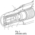
- the autoinjector has an outer housing in which is contained a syringe comprising a barrel containing medicament and a needle 1 at the front end thereof.
- the needle 1 is embedded in a rubber moulding 2 which, in turn, is closely surrounded by a rigid, preferably nylon, needle cover 3.
- An endcap 4 protects all of these components and is attached to the front end of the autoinjector's outer housing.
- the endcap, needle cover and rubber moulding are used to protect the needle end of the autoinjector during transit, storage and before use to deliver an injection.
- the endcap 4 has the further advantage of preventing accidental or unintended activation of the autoinjector, as it is not possible to fire the autoinjector with the endcap 4 in place.
- the needle cover and rubber moulding are firmly fixed on the needle 1 and it is difficult, if not impossible, for a patient to pull them from the needle using his/her fingers alone because of their position inside the nozzle of the autoinjector.
- the outer endcap 4 is provided not only to improve the aesthetic appearance of the injection device, before use, but also serves the function of facilitating the removal of the nylon sheath and rubber moulding.
- the endcap 4 is releasably retained on the front end of the injection device.
- the patient grips the endcap and pulls axially in the direction indicated by the arrow.
- tabs 5 are urged against the rear of the needle cover 3 and sufficient force can be applied thereby to disengage the needle 1 from the rubber moulding 2. In this way, the entire moulding 2, needle cover 3 and endcap 4 can be removed from the autoinjector and discarded, so that the autoinjector is then ready to use.
- Other variants of the same principle are also known.
- a problem is that as the rubber moulding is pulled from the needle, the needle is subjected to an axial force which in turn pulls the syringe (to which the needle is attached) axially forward.
- the forward axial force is suddenly removed and the barrel of the syringe can "bounce back" against other internal components of the autoinjector.
- the barrel of a syringe is usually glass, since glass has the most favourable storage properties for many drugs.
- glass is notoriously fragile and there is a risk of damage or breakage of the syringe if the forces to which the syringe is subjected are not properly controlled. The applicant has recognised that there is a risk of breakage caused by the "bounce back" described above.
- Syringe barrels made of materials other than glass, for example polyethylene or cyclic olefin polymers are less brittle when subjected to normal forces during injection, but still would benefit from the invention described herein.
- the risk of the syringe breaking is not only inconvenient and costly but is also potentially dangerous. If breakage occurs, it is possible that glass fragments and/or the needle may become detached and exit the front of the device causing injury. Furthermore, there is the risk that the remaining medicament will leak or be ejected from the device in an uncontrolled manner, potentially delivering the wrong dose into the patient, or causing injury e.g. if the medicament contacts the patient's skin or eyes.
- FIG. 2 One example of an autoinjector is illustrated in Figure 2 .
- the front housing 6 of the autoinjector is provided with gripping means in the form of one or more flexible fingers 7. These fingers are initially forced radially-outwardly by the presence of the needle cover 3. However, as soon a gap is created behind the needle cover 3 as it begins to be pulled axially from the needle 1, the fingers 7 flex radially-inwardly so as grip and to prevent the front of the barrel 8 and/or syringe support means moving axially forward too.
- the flexible fingers 7 are relatively weak and are not resilient enough to resist the significantly stronger forward axial force supplied by the autoinjector's main energy source (usually a spring).
- the rapidly forward moving barrel 8 and/or syringe support means forces the fingers 7 radially-outwardly, out of their path. Tapering of the abutting surfaces of the fingers 7 and barrel may facilitate this.
- Figure 3 shows a modified inner housing 9 for an autoinjector of the type described in, for example, WO 2005/070481 .
- the inner housing 9 is provided with gripping means in the form of one or more barbed hooks 10 at the front end thereof.
- Figure 3 shows an inner housing 9 having a generally square cross-sectional shape, but as illustrated in Figure 4 an inner housing of generally circular cross-sectional shape (as in WO 2005/070481 ) may equally be provided with hooks 10.
- the hooks 10 are designed to grip the finger flange of a syringe barrel and/or to grip the flange seat 11 of a syringe holder of the type described in, for example, WO 2005/070481 .
- the hooks 10 are strong enough to substantially prevent forward axial movement of the barrel and/or syringe holder caused by pulling the rubber moulding from the needle.
- the hooks 10 are not strong enough to resist the axial force supplied by the autoinjector's main energy source.
- the inner housing 9 moves rapidly forwards together with the syringe holder and therefore hooks 10 do not affect the actuation of the device to deliver an injection.
- the hooks 10 are relatively weak and capable of being forced radially-outwardly, out of the axial path of the syringe holder.
- the gripping means are located on the inner housing and grip the flange seat of the syringe holder and/or finger flange of the barrel.
- the gripping means could be located on the flange seat of the syringe holder so as to grip a part of the inner housing.
- Figure 5 shows an intermediate housing which, in this case, is the front housing 6 of the device. At least part of the front housing 6 is located within an outer housing 24 and preferably intermediate the outer housing 24 and syringe holder 20. At least one radially-flexible lever 6a is attached to or is part of the front housing providing blocking means which will be described in more detail below,
- the intermediate housing comprises the front housing 6, although it should be noted that the blocking means (e.g. lever 6a) described in connection with Figures 5 and 6 may alternatively be attached to a rear housing of the device.
- the lever 6a is radially-flexible such that when the endcap 4 is in place on the front end of the outer housing 24, the lever 6a is urged radially inwards into the axial path of the syringe holder 20 by interference with a rib 4a projecting radially inwards from the endcap 4.
- the front end of syringe holder 20 abuts the lever 6a, preventing forward axial movement of the syringe holder 6a and syringe contained therein. It is preferred that the lever 6a normally abuts the front end of the syringe holder 20, although it is envisaged that a small gap may be present. However, such a gap is less desirable and should be minimised.
- Figure 7 discloses an alternative mechanism for preventing undesired forward axial movement of the syringe holder 20.
- blocking means are provided in the form of at least one lever 23 attached to the rear housing 22, wherein the rear housing 22 is an intermediate housing according to the definition above.
- the lever 23 comprises two sections; a radially flexible first section 23a extending from the rear housing 22 substantially parallel the longitudinal axis of the device, and a preferably non-resilient second section 23b projecting radially outwards, substantially perpendicular to the first section 23a.
- the second section 23b Prior to actuating the device to deliver an injection, as shown in Figure 7 , the second section 23b abuts an inner surface of the outer housing 24 urging the lever 23 radially inwards into the axial path of the syringe holder 20.
- the lever 23 When flexed inwards, the presence of the lever 23 prevents forward axial movement of the syringe holder 20 and syringe. Therefore, when the endcap and needle sheath are removed from the front of the device, "bounceback" of the syringe holder and/or syringe is prevented.
Landscapes
- Health & Medical Sciences (AREA)
- Vascular Medicine (AREA)
- Engineering & Computer Science (AREA)
- Anesthesiology (AREA)
- Biomedical Technology (AREA)
- Heart & Thoracic Surgery (AREA)
- Hematology (AREA)
- Life Sciences & Earth Sciences (AREA)
- Animal Behavior & Ethology (AREA)
- General Health & Medical Sciences (AREA)
- Public Health (AREA)
- Veterinary Medicine (AREA)
- Infusion, Injection, And Reservoir Apparatuses (AREA)
Description
- This invention relates to the field of autoinjectors for the administration of liquid medication, for example, interferon.
- An autoinjector is an automatic injection device designed to facilitate delivery of a dose of medicament to a patient through a hypodermic needle, the injection usually being administered by the patient themselves. An autoinjector works, for example, by delivering an injection automatically upon actuation by the patient pressing a button, moving a lever or part of a housing etc. This is in contrast to a conventional manual syringe where the patient themselves needs to directly depress a plunger into a barrel containing medicament in order to effect the injection. The terms "autoinjector" and "injection device" are used interchangeably in the following description.
- One typical known autoinjector is described in
WO00/09186 - Another autoinjector is described in our co-pending international patent application, published under number
WO 2005/070481 . Some of the reference numerals in the present application correspond with the equivalent components in the device described inWO 2005/070481 . This device requires that the needle is moved axially so that it can appear beyond the end of the nozzle for the duration of the injection, after which the needle retracts automatically, so that it is never in sight of the user. The device also requires that the plunger is moved axially so that medicament is ejected. The overall complexity of the autoinjector is significantly reduced by both of these requirements being effected by one component, namely an inner housing and the device has the significant advantage that it can be built around a conventional or standard syringe presentation. - The injection device of
WO 2005/070481 is designed to be used in conjunction with a standard drug presentation e.g. a syringe comprising a needle, barrel preloaded with medicament and a plunger. The present invention is relevant to any injection device for use in conjunction with a syringe (whether preloaded or not and whether single-use or reusable), not only the device described inWO 2005/070481 . - In the known device described in our co-pending patent application no
WO 2005/070481 , the syringe is supported within the injection device by a barrel orsyringe holder 9. The syringe holder is sometimes referred to as a "syringe support means". Thesyringe holder 9 comprises an elongate housing which closely surrounds the glass barrel of the syringe. An improved syringe holder is described in our co-pending UK patent application number0620163.6 filed 12 October 2006 - A potential problem arises when the needle cover of an autoinjector is removed, in preparation for delivering an injection. An autoinjector is usually supplied to the patient with the needle of the syringe embedded in a rubber or other elastomeric sheath. The rubber sheath is in turn closely surrounded by a rigid needle cover which protects the needle from damage. Both the rubber sheath and rigid needle cover need to be removed before an injection can be delivered. Actuation of the autoinjector to deliver an injection occurs by actuating the main energy source (usually a spring) of the autoinjector. Prior to that, removal of the rubber sheath and rigid needle cover is usually achieved by providing some kind of gripping means on the interior of the autoinjector's end-cap, so that when the patient pulls the end-cap off the device, the rubber sheath and rigid needle cover are simultaneously removed with the end-cap. In a device such as that described in
WO 2005/070481 , even when ready to deliver an injection, the unsheathed needle is not exposed to the patient because it is located wholly within the autoinjector's housing. - As the rubber sheath is pulled from the needle, the needle is subjected to a forward axial force which in turn pulls the syringe (to which the needle is attached), moving it slightly axially forward. When the needle comes free of the rubber sheath, the forward axial force is suddenly removed and the needle and syringe can "bounce back" against other internal components of the autoinjector to its original axial position.
-
GB-A-2414398 -
DE-A-102004060146 (Tecpharma Licensing AG) also describes an auto-injector device with a latching component. To disengage the latching component, a needle protecting tube is shifted backwards and forces a latching tongue 21 outwards, which then exposes the flange of the sliding sleeve. -
WO-A-2007/132353 (Becton Dickinson France) describes an automatic injection device that includes flexible tongues that, when engaged, prevent a syringe container moving. Movement of a safety shield causes contact with the radially flexible tongues and causes them to deflect radially, thereby disengaging from the radial rim of the inner ring in which they were engaged. - It is an object of the present invention to provide an improved autoinjector which seeks to alleviate the above-described problems.
- According to a first aspect of the invention, there is provided an autoinjector comprising
- an outer housing in which can be mounted a syringe for holding a volume of medicament, the syringe for holding medicament having a needle at one end thereof,
- a syringe holder for supporting the syringe in an axial position relative to the outer housing, and
- an intermediate housing at least part of which is located within said outer housing and said syringe holder,
said intermediate housing being provided with a blocking means capable of abutting the syringe or the syringe holder so as to be capable of preventing forward axial movement of the syringe when a forward axial force is applied to said needle before actuation of the autoinjector to deliver an injection, but incapable of preventing forward axial movement of the syringe during actuation of the autoinjector to deliver an injection; - wherein said blocking means are moveable between a first blocking position in which said blocking means abut the syringe or syringe holder so as to block their axial path and a second, non-blocking position in which said blocking means do not block the axial path of the syringe or syringe holder;
- said blocking means comprising one or more fingers that are radially flexible substantially into and out of the axial path of said syringe or syringe holder;
- characterised in that in the first blocking position, the radially-flexible fingers are flexed inwardly by means of an interference fit with said outer housing, an end cap or a needle cover, and in moving from the first blocking position to the second non-blocking position, the radially-flexible fingers spring radially out of the axial path of the syringe or syringe holder so as to locate in a recess or aperture in said respective outer housing, end cap or needle cover.
- Preferably the blocking means are capable of abutting the forwardmost part of the syringe or the syringe holder.
- In one embodiment, said blocking means are movable from said first position to said second position upon removal of a needle cover from said needle and/or removal of an end cap from the front end of the autoinjector. This automatic movement has the advantage of not requiring any positive additional action by the user, other than the normal removal of the autoinjector's end cap.
- Preferably, the autoinjector is a single-use autoinjector. The simple construction of the autoinjector makes it very appropriate for applications such as emergency use for injecting a large population to control a pandemic, where a large number of cost-effective disposable autoinjectors are required. A single-use autoinjector also provides a very convenient means for patients to administer their own injections, even if lacking in dexterity and/or experience.
- Typically, the autoinjector contains an energy source, for example a spring, for moving said plunger axially in the barrel to deliver an injection in less than 30 seconds.
- Preferably, the syringe is axially moveable in said housing and is biased so that the needle is normally wholly inside said housing, wherein before injection the syringe is movable axially so as to move at least a part of said needle out of the housing and wherein after injection, the syringe is able to retract in order to retract said part of said needle into the housing. The concealment of the needle both before and after injection makes the autoinjector particularly suitable where the patient has any aversion to injection by needle. Concealment of the needle both before and after injection also eliminates the risk of needle-stick injury.
- Further features of the invention are defined in the appended claims.
- Preferred embodiments of the present invention will now be more particularly described, by way of example only, with reference to the accompanying drawings in which:
-
Figure 1 (PRIOR ART) is a perspective view, partly in cross-section of the front end of a known autoinjector; -
Figure 2 is a side view, partly in cross-section of the front end of an autoinjector according to a first example; -
Figure 3 is a perspective view of the modified inner housing of an autoinjector according to a second example; -
Figure 4 shows how the inner housing ofFig. 3 grips a syringe holder to prevent axial movement of the syringe holder and syringe contained therein; -
Figure 5 is a partial cross sectional view of an autoinjector according to an embodiment of the invention, wherein a flexible lever is urged radially inwards preventing axial movement of the syringe holder and syringe contained therein; -
Figure 6 is a partial cross sectional view of the autoinjector ofFig. 5 , wherein the endcap has been removed and the flexible lever is in a relaxed state; -
Figure 7 is a partial cross sectional view of an autoinjector according to another embodiment of the invention, wherein a flexible lever is urged radially inwards preventing axial movement of the syringe holder and syringe contained therein; and -
Figure 8 is a partial cross sectional view of the autoinjector ofFig. 7 , wherein the lever is in relaxed state following the forward movement of the outer housing. - Throughout the description and claims of this specification, the words "comprise" and "contain" and variations of the words, for example "comprising" and "comprises", means "including but not limited to", and is not intended to (and does not) exclude other components, integers or steps.
- Throughout the description and claims of this specification, the singular encompasses the plural unless the context otherwise requires. In particular, where the indefinite article is used, the specification is to be understood as contemplating plurality as well as singularity, unless the context requires otherwise.
- Throughout the following description, reference to a "forward" direction means the direction which is towards the patient when the injection device is in use. The "forward" end of the injection device is the end nearest the patient's skin when the device is in use. Similarly, reference to a "rearward" direction means the direction which is away from the patient and the "rearward" end of the device is the end furthest from the patient's skin when the injection device is in use.
- Features, integers, characteristics or groups described in conjunction with a particular aspect, embodiment or example of the invention are to be understood to be applicable to any other aspect, embodiment or example described herein unless incompatible therewith.
- Referring to
Figure 1 (PRIOR ART), the autoinjector has an outer housing in which is contained a syringe comprising a barrel containing medicament and aneedle 1 at the front end thereof. Theneedle 1 is embedded in arubber moulding 2 which, in turn, is closely surrounded by a rigid, preferably nylon,needle cover 3. Anendcap 4 protects all of these components and is attached to the front end of the autoinjector's outer housing. - The endcap, needle cover and rubber moulding are used to protect the needle end of the autoinjector during transit, storage and before use to deliver an injection. The
endcap 4 has the further advantage of preventing accidental or unintended activation of the autoinjector, as it is not possible to fire the autoinjector with theendcap 4 in place. - The needle cover and rubber moulding are firmly fixed on the
needle 1 and it is difficult, if not impossible, for a patient to pull them from the needle using his/her fingers alone because of their position inside the nozzle of the autoinjector. Theouter endcap 4 is provided not only to improve the aesthetic appearance of the injection device, before use, but also serves the function of facilitating the removal of the nylon sheath and rubber moulding. - The
endcap 4 is releasably retained on the front end of the injection device. When it is desired to remove theendcap 4 from the device, the patient grips the endcap and pulls axially in the direction indicated by the arrow. In the illustrated example,tabs 5 are urged against the rear of theneedle cover 3 and sufficient force can be applied thereby to disengage theneedle 1 from therubber moulding 2. In this way, theentire moulding 2,needle cover 3 andendcap 4 can be removed from the autoinjector and discarded, so that the autoinjector is then ready to use. Other variants of the same principle are also known. - As mentioned above, a problem is that as the rubber moulding is pulled from the needle, the needle is subjected to an axial force which in turn pulls the syringe (to which the needle is attached) axially forward. When the needle comes free of the rubber sheath, the forward axial force is suddenly removed and the barrel of the syringe can "bounce back" against other internal components of the autoinjector.
- The barrel of a syringe is usually glass, since glass has the most favourable storage properties for many drugs. However, glass is notoriously fragile and there is a risk of damage or breakage of the syringe if the forces to which the syringe is subjected are not properly controlled. The applicant has recognised that there is a risk of breakage caused by the "bounce back" described above. Syringe barrels made of materials other than glass, for example polyethylene or cyclic olefin polymers are less brittle when subjected to normal forces during injection, but still would benefit from the invention described herein.
- The risk of the syringe breaking is not only inconvenient and costly but is also potentially dangerous. If breakage occurs, it is possible that glass fragments and/or the needle may become detached and exit the front of the device causing injury. Furthermore, there is the risk that the remaining medicament will leak or be ejected from the device in an uncontrolled manner, potentially delivering the wrong dose into the patient, or causing injury e.g. if the medicament contacts the patient's skin or eyes.
- One example of an autoinjector is illustrated in
Figure 2 . Thefront housing 6 of the autoinjector is provided with gripping means in the form of one or moreflexible fingers 7. These fingers are initially forced radially-outwardly by the presence of theneedle cover 3. However, as soon a gap is created behind theneedle cover 3 as it begins to be pulled axially from theneedle 1, thefingers 7 flex radially-inwardly so as grip and to prevent the front of thebarrel 8 and/or syringe support means moving axially forward too. - However, the
flexible fingers 7 are relatively weak and are not resilient enough to resist the significantly stronger forward axial force supplied by the autoinjector's main energy source (usually a spring). When the autoinjector is actuated for delivery of an injection, the rapidly forward movingbarrel 8 and/or syringe support means forces thefingers 7 radially-outwardly, out of their path. Tapering of the abutting surfaces of thefingers 7 and barrel may facilitate this. - Another example of an autoinjector is illustrated in
Figure 3. Figure 3 shows a modifiedinner housing 9 for an autoinjector of the type described in, for example,WO 2005/070481 . Theinner housing 9 is provided with gripping means in the form of one or morebarbed hooks 10 at the front end thereof.Figure 3 shows aninner housing 9 having a generally square cross-sectional shape, but as illustrated inFigure 4 an inner housing of generally circular cross-sectional shape (as inWO 2005/070481 ) may equally be provided withhooks 10. As shown inFigure 4 , thehooks 10 are designed to grip the finger flange of a syringe barrel and/or to grip theflange seat 11 of a syringe holder of the type described in, for example,WO 2005/070481 . - As with the flexible fingers of the example shown in
Figure 2 , thehooks 10 are strong enough to substantially prevent forward axial movement of the barrel and/or syringe holder caused by pulling the rubber moulding from the needle. However, thehooks 10 are not strong enough to resist the axial force supplied by the autoinjector's main energy source. When the autoinjector is actuated for delivery of an injection, theinner housing 9 moves rapidly forwards together with the syringe holder and therefore hooks 10 do not affect the actuation of the device to deliver an injection. In any case, thehooks 10 are relatively weak and capable of being forced radially-outwardly, out of the axial path of the syringe holder. - In the examples illustrated in
Figures 3 and4 , the gripping means (hooks 10) are located on the inner housing and grip the flange seat of the syringe holder and/or finger flange of the barrel. Alternatively, the gripping means could be located on the flange seat of the syringe holder so as to grip a part of the inner housing. - An embodiment of the present invention is illustrated in
Figures 5 and 6. Figure 5 shows an intermediate housing which, in this case, is thefront housing 6 of the device. At least part of thefront housing 6 is located within anouter housing 24 and preferably intermediate theouter housing 24 andsyringe holder 20. At least one radially-flexible lever 6a is attached to or is part of the front housing providing blocking means which will be described in more detail below, - In the specific embodiment of
Figure 5 , the intermediate housing comprises thefront housing 6, although it should be noted that the blocking means (e.g. lever 6a) described in connection withFigures 5 and 6 may alternatively be attached to a rear housing of the device. Thelever 6a is radially-flexible such that when theendcap 4 is in place on the front end of theouter housing 24, thelever 6a is urged radially inwards into the axial path of thesyringe holder 20 by interference with arib 4a projecting radially inwards from theendcap 4. Thus, when theendcap 4 is in place, the front end ofsyringe holder 20 abuts thelever 6a, preventing forward axial movement of thesyringe holder 6a and syringe contained therein. It is preferred that thelever 6a normally abuts the front end of thesyringe holder 20, although it is envisaged that a small gap may be present. However, such a gap is less desirable and should be minimised. - When the patient is ready to use the autoinjector, he pulls the
endcap 4 off the device axially forwards. Simultaneously, the needle cover (not illustrated) is pulled from the needle. Once the needle cover is clear of the needle (and the point at which "bounceback" might occur when forward axial force on the needle is suddenly released has passed), therib 4a passes over thelever 6a and eventually clears it such that thelever 6a is no longer urged radially inwards and is free to spring radially out of the axial path of thesyringe holder 20 as shown inFigure 6 . The communicating surfaces of therib 4a and thelever 6a may be tapered to facilitate smooth movement therebetween.Figure 6 shows thelever 6a in a relaxed position following the removal of theendcap 4. Once theendcap 4 is completely removed, thesyringe holder 20 is free to move axially forward when the device is actuated to deliver an injection. - A further embodiment is illustrated in
Figures 7 and 8. Figure 7 discloses an alternative mechanism for preventing undesired forward axial movement of thesyringe holder 20. In the specific embodiment ofFigure 7 , blocking means are provided in the form of at least onelever 23 attached to therear housing 22, wherein therear housing 22 is an intermediate housing according to the definition above. Thelever 23 comprises two sections; a radially flexiblefirst section 23a extending from therear housing 22 substantially parallel the longitudinal axis of the device, and a preferably non-resilientsecond section 23b projecting radially outwards, substantially perpendicular to thefirst section 23a. - Prior to actuating the device to deliver an injection, as shown in
Figure 7 , thesecond section 23b abuts an inner surface of theouter housing 24 urging thelever 23 radially inwards into the axial path of thesyringe holder 20. When flexed inwards, the presence of thelever 23 prevents forward axial movement of thesyringe holder 20 and syringe. Therefore, when the endcap and needle sheath are removed from the front of the device, "bounceback" of the syringe holder and/or syringe is prevented. - Upon actuating the device to deliver an injection, forward movement of the
outer housing 24 relative to therear housing 22 causes thesecond section 23b to move into anaperture 24a in theouter housing 24 when the two become aligned transverse the longitudinal axis. Alternatively, theouter housing 24 may have a recess into which thesecond section 23b can move into. The communicating surfaces of thelever 23 andouter housing 24 may be tapered to facilitate easy movement of thelever 23 into theaperture 24a. Movement of thesecond section 23b into theaperture 24a causes thelever 23 to flex radially outwards, out of the axial path of thesyringe holder 20.Figure 8 shows thelever 23 in a relaxed state, with thesecond section 23b aligned with theaperture 24a transverse the longitudinal axis of the device. In the relaxed state, thesyringe holder 20 and syringe are free to move axially forward upon actuation of the device. - The reader's attention is directed to all papers and documents which are filed concurrently with or previous to this specification in connection with this application and which are open to public inspection with this specification.
- All of the features disclosed in this specification (including any accompanying claims, abstract and drawings), and/or all of the steps of any method or process so disclosed, may be combined in any combination, except combinations where at least some of such features and/or steps are mutually exclusive.
- Each feature disclosed in this specification (including any accompanying claims, abstract and drawings), may be replaced by alternative features serving the same, equivalent or similar purpose, unless expressly stated otherwise. Thus, unless expressly stated otherwise, each feature disclosed is one example only of a generic series of equivalent or similar features.
- The invention is not restricted to the details of any foregoing embodiments. The invention extends to any novel one, or any novel combination, of the features disclosed in this specification (including any accompanying claims, abstract and drawings), or to any novel one, or any novel combination, of the steps of any method or process so disclosed.
Claims (9)
- An autoinjector comprising
an outer housing (24) in which can be mounted a syringe for holding a volume of medicament, the syringe for holding medicament having a needle at one end thereof,
a syringe holder (20) for supporting the syringe in an axial position relative to the outer housing (24), and
an intermediate housing (6,22) at least part of which is located within said outer housing (24),
said intermediate housing (6,22) being provided with a blocking means capable of abutting the syringe or the syringe holder (20) so as to be capable of preventing forward axial movement of the syringe when a forward axial force is applied to said needle before actuation of the autoinjector to deliver an injection, but incapable of preventing forward axial movement of the syringe during actuation of the autoinjector to deliver an injection;
wherein said blocking means are moveable between a first blocking position in which said blocking means abut the syringe or syringe holder (20) so as to block their axial path and a second, non-blocking position in which said blocking means do not block the axial path of the syringe or syringe holder;
said blocking means comprising one or more fingers (6a,23) that are radially flexible substantially into and out of the axial path of said syringe or syringe holder (20);
characterised in that in the first blocking position, the radially-flexible fingers (6a,23) are flexed inwardly by means of an interference fit with said outer housing (24), an end cap (4) or a needle cover, and in moving from the first blocking position to the second non-blocking position, the radially-flexible fingers (6a,23) spring radially out of the axial path of the syringe or syringe holder 20 so as to locate in a recess or aperture (24a) in said respective outer housing (24), end cap (4) or needle cover. - An autoinjector as claimed in claim 1 wherein said blocking means are capable of abutting the forwardmost part of the syringe or the syringe holder (20).
- An autoinjector as claimed in claim 1 or 2, wherein said blocking means are movable from said first position to said second position upon removal of a needle cover from said needle and/or removal of an end cap (4) from the front end of the autoinjector.
- The autoinjector of any of the preceding claims wherein said intermediate housing (6,22) is a front housing (6) or a rear housing (22) of the autoinjector.
- The autoinjector as claimed in any of the preceding claims wherein said forward axial force is a pulling force on said needle; and/or
wherein said autoinjector is a single-use autoinjector; and/or
further comprising an energy source capable of delivering an injection from the syringe in less than 30 seconds. - The autoinjector of any of the preceding claims wherein the syringe is axially moveable in said housing (24) and is biased so that the needle is normally wholly inside said housing (24), wherein before injection the syringe is movable axially so as to move at least a part of said needle out of the housing (24) and wherein after injection, the syringe is able to retract in order to retract said part of said needle into the housing (24).
- The autoinjector of claim 6 wherein an inner housing (9) is moveable by said energy source between three positions, namelya first position in which the inner housing (9) is in communication with the barrel of the syringe such that, in use, the barrel is movable axially so as to move at least part of said needle out of the outer housing (24);a second position in which the inner housing (9) is in communication with a plunger of the syringe but not the barrel such that, in use, said plunger is movable axially into said barrel so as to expel medicament through the needle; anda third position in which the inner housing (9) is in communication with neither the plunger nor the barrel such that, in use, the plunger and barrel are able to retract in order to retract the needle into the outer housing (24).
- The autoinjector of any of claim 7 wherein said inner housing (9) is a unitary component; and/or
wherein said syringe holder (20) is generally cylindrical and of a diameter less than the diameter of the finger flange of the syringe so that the syringe support means is suitably sized to closely surround the barrel of the syringe, in use. - The autoinjector as claimed in any of the preceding claims, in which is mounted a syringe for holding a volume of medicament, the syringe having a needle at one end thereof.
Applications Claiming Priority (2)
| Application Number | Priority Date | Filing Date | Title |
|---|---|---|---|
| GBGB0625169.8A GB0625169D0 (en) | 2006-12-18 | 2006-12-18 | Improved autoinjector |
| PCT/GB2007/004870 WO2008075033A1 (en) | 2006-12-18 | 2007-12-18 | Improved autoinjector |
Publications (2)
| Publication Number | Publication Date |
|---|---|
| EP2146762A1 EP2146762A1 (en) | 2010-01-27 |
| EP2146762B1 true EP2146762B1 (en) | 2018-09-26 |
Family
ID=37712305
Family Applications (1)
| Application Number | Title | Priority Date | Filing Date |
|---|---|---|---|
| EP07848606.5A Active EP2146762B1 (en) | 2006-12-18 | 2007-12-18 | Improved autoinjector |
Country Status (7)
| Country | Link |
|---|---|
| US (1) | US8747357B2 (en) |
| EP (1) | EP2146762B1 (en) |
| AU (1) | AU2007336082B9 (en) |
| CA (1) | CA2687758C (en) |
| ES (1) | ES2692210T3 (en) |
| GB (2) | GB0625169D0 (en) |
| WO (1) | WO2008075033A1 (en) |
Families Citing this family (71)
| Publication number | Priority date | Publication date | Assignee | Title |
|---|---|---|---|---|
| GB2414402B (en) | 2004-05-28 | 2009-04-22 | Cilag Ag Int | Injection device |
| GB2414400B (en) | 2004-05-28 | 2009-01-14 | Cilag Ag Int | Injection device |
| GB2414775B (en) | 2004-05-28 | 2008-05-21 | Cilag Ag Int | Releasable coupling and injection device |
| US7947017B2 (en) | 2004-11-22 | 2011-05-24 | Intelliject, Inc. | Devices, systems and methods for medicament delivery |
| US7648483B2 (en) | 2004-11-22 | 2010-01-19 | Intelliject, Inc. | Devices, systems and methods for medicament delivery |
| US11590286B2 (en) | 2004-11-22 | 2023-02-28 | Kaleo, Inc. | Devices, systems and methods for medicament delivery |
| AU2004325202B2 (en) | 2004-11-22 | 2009-02-19 | Kaleo, Inc. | Devices, systems, and methods for medicament delivery |
| US10737028B2 (en) | 2004-11-22 | 2020-08-11 | Kaleo, Inc. | Devices, systems and methods for medicament delivery |
| DK2058020T3 (en) | 2005-02-01 | 2013-01-07 | Intelliject Inc | Device for administering drug |
| GB2424836B (en) | 2005-04-06 | 2010-09-22 | Cilag Ag Int | Injection device (bayonet cap removal) |
| GB2425062B (en) | 2005-04-06 | 2010-07-21 | Cilag Ag Int | Injection device |
| GB2427826B (en) | 2005-04-06 | 2010-08-25 | Cilag Ag Int | Injection device comprising a locking mechanism associated with integrally formed biasing means |
| DE602005018480D1 (en) | 2005-08-30 | 2010-02-04 | Cilag Gmbh Int | Needle device for a prefilled syringe |
| US20110098656A1 (en) | 2005-09-27 | 2011-04-28 | Burnell Rosie L | Auto-injection device with needle protecting cap having outer and inner sleeves |
| GB0601309D0 (en) | 2006-01-23 | 2006-03-01 | Medical House The Plc | Injection device |
| US20070173770A1 (en) | 2006-01-23 | 2007-07-26 | The Medical House Plc | Injection device |
| GB2438591B (en) | 2006-06-01 | 2011-07-13 | Cilag Gmbh Int | Injection device |
| GB2438590B (en) | 2006-06-01 | 2011-02-09 | Cilag Gmbh Int | Injection device |
| GB2438593B (en) * | 2006-06-01 | 2011-03-30 | Cilag Gmbh Int | Injection device (cap removal feature) |
| GB0704351D0 (en) | 2007-03-07 | 2007-04-11 | Medical House Plc The | Improved autoinjector |
| GB2451665B (en) * | 2007-08-08 | 2012-09-26 | Cilag Gmbh Int | Injection device |
| GB2451662B (en) | 2007-08-08 | 2012-09-19 | Cilag Gmbh Int | Injection device |
| GB0806814D0 (en) * | 2008-04-15 | 2008-05-14 | Medical House Plc The | Improved autoinjector |
| US8052645B2 (en) | 2008-07-23 | 2011-11-08 | Avant Medical Corp. | System and method for an injection using a syringe needle |
| MX384690B (en) | 2008-05-20 | 2025-03-14 | Avant Medical Corp | AUTO-INJECTOR SYSTEM. |
| US8177749B2 (en) | 2008-05-20 | 2012-05-15 | Avant Medical Corp. | Cassette for a hidden injection needle |
| GB2461086B (en) | 2008-06-19 | 2012-12-05 | Cilag Gmbh Int | Injection device |
| GB2461084B (en) | 2008-06-19 | 2012-09-26 | Cilag Gmbh Int | Fluid transfer assembly |
| GB2461087B (en) | 2008-06-19 | 2012-09-26 | Cilag Gmbh Int | Injection device |
| GB2461085B (en) | 2008-06-19 | 2012-08-29 | Cilag Gmbh Int | Injection device |
| GB2461089B (en) | 2008-06-19 | 2012-09-19 | Cilag Gmbh Int | Injection device |
| US12097357B2 (en) | 2008-09-15 | 2024-09-24 | West Pharma. Services IL, Ltd. | Stabilized pen injector |
| GB2469672B (en) | 2009-04-23 | 2013-09-25 | Medical House Ltd | Improved autoinjector |
| EP2536452B1 (en) | 2010-02-18 | 2018-08-29 | Sanofi-Aventis Deutschland GmbH | Auto-injector |
| EP2468338A1 (en) * | 2010-12-21 | 2012-06-27 | Sanofi-Aventis Deutschland GmbH | Auto-injector |
| EP2468343A1 (en) * | 2010-12-21 | 2012-06-27 | Sanofi-Aventis Deutschland GmbH | Front end for an auto-injector |
| GB201021764D0 (en) * | 2010-12-22 | 2011-02-02 | Owen Mumford Ltd | Autoinjectors |
| US8939943B2 (en) | 2011-01-26 | 2015-01-27 | Kaleo, Inc. | Medicament delivery device for administration of opioid antagonists including formulations for naloxone |
| US9173999B2 (en) | 2011-01-26 | 2015-11-03 | Kaleo, Inc. | Devices and methods for delivering medicaments from a multi-chamber container |
| US8627816B2 (en) | 2011-02-28 | 2014-01-14 | Intelliject, Inc. | Medicament delivery device for administration of opioid antagonists including formulations for naloxone |
| CA3021845C (en) | 2011-04-20 | 2022-03-29 | Amgen Inc. | Autoinjector apparatus |
| JP5960296B2 (en) * | 2012-03-14 | 2016-08-02 | ケアベイ・ヨーロッパ・リミテッドCarebay Europe Limited | Drug delivery device |
| USD898908S1 (en) | 2012-04-20 | 2020-10-13 | Amgen Inc. | Pharmaceutical product cassette for an injection device |
| USD808010S1 (en) | 2012-04-20 | 2018-01-16 | Amgen Inc. | Injection device |
| EP2968775B1 (en) | 2013-03-15 | 2019-12-18 | Amgen Inc. | Drug cassette, autoinjector, and autoinjector system |
| TWI580451B (en) | 2013-03-15 | 2017-05-01 | 安美基公司 | Cassette for an injector and method of using an autoinjector apparatus having an autoinjector and a cassette |
| EP3590568A1 (en) | 2013-03-22 | 2020-01-08 | TecPharma Licensing AG | Substance dispensing device with a signalling device |
| GB2515032A (en) | 2013-06-11 | 2014-12-17 | Cilag Gmbh Int | Guide for an injection device |
| GB2515039B (en) | 2013-06-11 | 2015-05-27 | Cilag Gmbh Int | Injection Device |
| GB2517896B (en) | 2013-06-11 | 2015-07-08 | Cilag Gmbh Int | Injection device |
| GB2515038A (en) | 2013-06-11 | 2014-12-17 | Cilag Gmbh Int | Injection device |
| GB201313888D0 (en) * | 2013-08-02 | 2013-09-18 | Consort Medical Plc | Assembly for an autoinjector device |
| US9517307B2 (en) | 2014-07-18 | 2016-12-13 | Kaleo, Inc. | Devices and methods for delivering opioid antagonists including formulations for naloxone |
| GB201416985D0 (en) | 2014-09-26 | 2014-11-12 | Ucb Biopharma Sprl And Bespak Europ Ltd | Housing part for an auto-injector |
| US9415176B1 (en) | 2015-01-22 | 2016-08-16 | West Pharmaceutical Services, Inc. | Autoinjector having an end-of-dose visual indicator |
| TW201705994A (en) * | 2015-06-03 | 2017-02-16 | 賽諾菲阿凡提斯德意志有限公司 | Automatic syringe and assembly method |
| TW201707741A (en) | 2015-06-03 | 2017-03-01 | 賽諾菲阿凡提斯德意志有限公司 | Needle guard gripper, lid, autoinjector and method of making the same |
| AU2016287571C1 (en) | 2015-06-30 | 2021-12-23 | Kaleo, Inc. | Auto-injectors for administration of a medicament within a prefilled syringe |
| CA3027992C (en) | 2016-06-22 | 2021-08-03 | Antares Pharma, Inc. | Needle-shield remover |
| EP3332823A1 (en) | 2016-12-07 | 2018-06-13 | Sanofi-Aventis Deutschland GmbH | A cap for an injection device |
| WO2018119218A1 (en) | 2016-12-23 | 2018-06-28 | Kaleo, Inc. | Medicament delivery device and methods for delivering drugs to infants and children |
| PT3801694T (en) | 2018-06-08 | 2025-10-30 | Antares Pharma Inc | Auto-insert injector |
| EP3626291A1 (en) * | 2018-09-21 | 2020-03-25 | Regeneron Pharmaceuticals, Inc. | Needle shield grip device |
| ES2959943T3 (en) * | 2018-10-05 | 2024-02-29 | Becton Dickinson France | Cover cap remover with sealing gasket compression |
| EP3902584A4 (en) | 2018-12-29 | 2022-09-07 | Kaleo, Inc. | DEVICES AND METHODS FOR DELIVERING SUBSTANCES IN A PRE-FILLED SYRINGE |
| US12558495B2 (en) | 2019-02-26 | 2026-02-24 | Becton Dickinson France | Auto-injector with cap |
| KR102655825B1 (en) | 2019-02-26 | 2024-04-08 | 벡톤 디킨슨 프랑스 | Auto-injection device with audible indicator |
| US12569625B2 (en) | 2019-02-26 | 2026-03-10 | Becton Dickinson France | Rigid needle shield remover with drop test feature for autoinjector |
| WO2020216918A1 (en) | 2019-04-26 | 2020-10-29 | Becton Dickinson France | Needle cover with undercut |
| US11167087B2 (en) | 2019-08-09 | 2021-11-09 | Kaleo, Inc. | Devices and methods for delivery of substances within a prefilled syringe |
| US12268847B1 (en) | 2021-02-10 | 2025-04-08 | Kaleo, Inc. | Devices and methods for delivery of substances within a medicament container |
Family Cites Families (90)
| Publication number | Priority date | Publication date | Assignee | Title |
|---|---|---|---|---|
| US60917A (en) | 1867-01-01 | Anson r | ||
| US2994323A (en) | 1958-12-11 | 1961-08-01 | American Home Prod | Cartridge-syringe assembly |
| US3702608A (en) | 1970-12-15 | 1972-11-14 | Robert C Tibbs | Painless injection device with powered plunger |
| US3756242A (en) | 1972-01-04 | 1973-09-04 | Micro Motors Inc | Mechanical scarifier |
| BE795162A (en) | 1972-02-10 | 1973-08-08 | Philips Nv | INJEKTIE-INRICHTING |
| US3811442A (en) | 1972-03-23 | 1974-05-21 | A Maroth | Hypodermic syringe holder and applicator |
| SE436687B (en) | 1981-12-14 | 1985-01-21 | Anders Blomberg | INJECTION DEVICE |
| US4958622A (en) | 1983-05-11 | 1990-09-25 | Selenke William M | Hypodermic syringe for taking and transporting a specimen |
| DE3715340C2 (en) | 1987-05-08 | 1995-10-19 | Haselmeier Wilhelm Fa | Injection device |
| US4913699A (en) | 1988-03-14 | 1990-04-03 | Parsons James S | Disposable needleless injection system |
| US5024656A (en) | 1988-08-30 | 1991-06-18 | Injet Medical Products, Inc. | Gas-pressure-regulated needleless injection system |
| US4923447A (en) | 1989-02-17 | 1990-05-08 | Morgan Michael W | Syringe assembly |
| US4976724A (en) | 1989-08-25 | 1990-12-11 | Lifescan, Inc. | Lancet ejector mechanism |
| US4990142A (en) | 1989-10-23 | 1991-02-05 | Gte Products Corporation | Hypodermic syringe |
| US5211625A (en) | 1990-03-20 | 1993-05-18 | Olympus Optical Co., Ltd. | Ultrasonic treatment apparatus |
| US5080653A (en) | 1990-04-16 | 1992-01-14 | Pacesetter Infusion, Ltd. | Infusion pump with dual position syringe locator |
| US5078698A (en) | 1991-02-19 | 1992-01-07 | Sterling Drug Inc. | Axial eject hypodermic syringe holder |
| GB9111600D0 (en) | 1991-05-30 | 1991-07-24 | Owen Mumford Ltd | Improvements relating to injection devices |
| US5300031A (en) | 1991-06-07 | 1994-04-05 | Liebel-Flarsheim Company | Apparatus for injecting fluid into animals and disposable front loadable syringe therefor |
| EP0518416A1 (en) | 1991-06-13 | 1992-12-16 | Duphar International Research B.V | Injection device |
| US5167632A (en) | 1992-01-24 | 1992-12-01 | New Potency Products, Inc. | Syringe |
| EP0768902B1 (en) | 1992-11-19 | 1998-07-15 | Tebro S.A. | Disposable auto-injector for prefilled syringes |
| US5320609A (en) | 1992-12-07 | 1994-06-14 | Habley Medical Technology Corporation | Automatic pharmaceutical dispensing syringe |
| JP3206843B2 (en) | 1992-12-18 | 2001-09-10 | 株式会社小松製作所 | 3D image measurement device |
| DE69427226T2 (en) | 1993-03-24 | 2001-08-30 | Owen Mumford Ltd., Woodstock | DEVICE FOR INJECTION |
| FR2715071B1 (en) | 1994-01-17 | 1996-03-01 | Aguettant Lab | Automatic drug injector. |
| US5478316A (en) | 1994-02-02 | 1995-12-26 | Becton, Dickinson And Company | Automatic self-injection device |
| FR2733687B1 (en) | 1995-05-04 | 1997-10-03 | Brunel Marc | METHOD FOR MANUFACTURING A PRE-FILLED INJECTION DEVICE CONTAINING A DOSE OF LIQUID TO BE INJECTED, AND INJECTION DEVICE PRODUCED |
| US5779675A (en) | 1995-08-25 | 1998-07-14 | Medrad, Inc. | Front load pressure jacket system with syringe holder |
| US5634906A (en) | 1995-12-27 | 1997-06-03 | Habley Medical Technology Corporation | Needle hiding shield for a dose metering syringe |
| US6203530B1 (en) | 1997-01-28 | 2001-03-20 | Pos-T-Vac, Inc. | Auto-injection device |
| US6171283B1 (en) | 1997-03-10 | 2001-01-09 | Safety Syringes, Inc. | Disposable self-shielding unit dose syringe guard |
| DE69819161T2 (en) | 1997-08-21 | 2004-07-08 | Ares Trading S.A. | injection device |
| AU4883797A (en) | 1997-11-03 | 1999-05-24 | Ermanno Greco | Self-injection device |
| DE69827036T2 (en) | 1997-12-16 | 2006-03-09 | Meridian Medical Technologies, Inc. | AUTOMATIC INJECTION DEVICE FOR THE ADMINISTRATION OF A MEDICAMENT |
| DE29801168U1 (en) | 1998-01-24 | 1999-08-12 | Medico Dev Investment Co | Injection device |
| DE19822031C2 (en) | 1998-05-15 | 2000-03-23 | Disetronic Licensing Ag | Auto injection device |
| US6428528B2 (en) | 1998-08-11 | 2002-08-06 | Antares Pharma, Inc. | Needle assisted jet injector |
| SE9803662D0 (en) * | 1998-10-26 | 1998-10-26 | Pharmacia & Upjohn Ab | autoinjector |
| US6689093B2 (en) | 1998-11-18 | 2004-02-10 | Bioject, Inc. | Single-use needle-less hypodermic jet injection apparatus and method |
| US6264629B1 (en) | 1998-11-18 | 2001-07-24 | Bioject, Inc. | Single-use needle-less hypodermic jet injection apparatus and method |
| US6368303B1 (en) | 1999-10-15 | 2002-04-09 | Becton, Dickinson And Company | Retracting needle syringe |
| PE20010720A1 (en) | 1999-12-11 | 2001-07-26 | Glaxo Group Ltd | MEDICATION DISTRIBUTOR |
| GB0003790D0 (en) | 2000-02-18 | 2000-04-05 | Astrazeneca Uk Ltd | Medical device |
| US6599281B1 (en) | 2000-05-03 | 2003-07-29 | Aspect Medical Systems, Inc. | System and method for adaptive drug delivery |
| US6517517B1 (en) | 2000-06-08 | 2003-02-11 | Mayo Foundation For Medical Education And Research | Automated injection device for administration of liquid medicament |
| WO2002017996A1 (en) | 2000-08-29 | 2002-03-07 | Novo Nordisk A/S | Automatic injection device with torsion function for retraction of needle |
| SE518981C2 (en) | 2000-12-14 | 2002-12-17 | Shl Medical Ab | autoinjector |
| US6471669B2 (en) | 2001-03-05 | 2002-10-29 | Bioject Medical Technologies Inc. | Disposable needle-free injection apparatus and method |
| US6752781B2 (en) | 2001-06-08 | 2004-06-22 | Sergio Landau | Durable hypodermic jet injector apparatus and method |
| US7563249B2 (en) | 2002-12-20 | 2009-07-21 | Medrad, Inc. | Syringe having an alignment flange, an extending lip and a radial expansion section of reduced wall thickness |
| US6607510B2 (en) | 2001-11-09 | 2003-08-19 | Bioject Medical Technologies Inc. | Disposable needle-free injection apparatus and method |
| EP1443992B1 (en) | 2001-11-09 | 2007-01-03 | Alza Corporation | Collapsible syringe cartridge |
| US20030105430A1 (en) | 2001-11-30 | 2003-06-05 | Elan Pharma International Limited Wil House | Automatic injector |
| GB2396298A (en) | 2002-12-17 | 2004-06-23 | Pa Consulting Services | Injection device and drive coupling |
| GB2388033A (en) | 2002-05-02 | 2003-11-05 | Pa Consulting Services | Automatic injection device |
| GB0211294D0 (en) | 2002-05-17 | 2002-06-26 | Owen Mumford Ltd | Improvements relating to injection devices |
| US6979316B1 (en) | 2002-05-23 | 2005-12-27 | Seedlings Life Science Ventures Llc | Apparatus and method for rapid auto-injection of medication |
| US7156823B2 (en) | 2002-06-04 | 2007-01-02 | Bioject Inc. | High workload needle-free injection system |
| GB2396816A (en) | 2002-12-17 | 2004-07-07 | Pa Consulting Services | Injection device |
| GB0312852D0 (en) | 2003-06-05 | 2003-07-09 | Owen Mumford Ltd | Improvements relating to syringe firing mechanisms |
| US7500963B2 (en) | 2003-07-22 | 2009-03-10 | Safety Syringes, Inc. | Systems and methods for automatic medical injection with safeguard |
| US20050027255A1 (en) | 2003-07-31 | 2005-02-03 | Sid Technologies, Llc | Automatic injector |
| US7635348B2 (en) | 2003-11-04 | 2009-12-22 | Meridian Medical Technologies, Inc. | Container for medicament automatic injector and automatic injector adapted therefor |
| DE10351599A1 (en) | 2003-11-05 | 2005-06-16 | Tecpharma Licensing Ag | Auto-injection device |
| US20050101919A1 (en) * | 2003-11-07 | 2005-05-12 | Lennart Brunnberg | Device for an injector |
| CH696421A5 (en) | 2003-12-18 | 2007-06-15 | Tecpharma Licensing Ag | Autoinjector with arresting the drug container. |
| GB2410188B (en) | 2004-01-23 | 2006-01-25 | Medical House Plc | Injection device |
| ES2296129T3 (en) | 2004-01-23 | 2008-04-16 | The Medical House Plc | INJECTION DEVICE. |
| GB2410190A (en) | 2004-01-26 | 2005-07-27 | Medical House Plc | Disposable gas-powered needle-free injection device |
| ATE426422T1 (en) * | 2004-04-29 | 2009-04-15 | Abbott Lab | AUTOINJECTOR WITH EXTENDABLE NEEDLE PROTECTION COVER |
| GB2414398B (en) | 2004-05-28 | 2009-04-22 | Cilag Ag Int | Injection device |
| GB2414401B (en) | 2004-05-28 | 2009-06-17 | Cilag Ag Int | Injection device |
| GB2414399B (en) | 2004-05-28 | 2008-12-31 | Cilag Ag Int | Injection device |
| US20060100589A1 (en) | 2004-08-10 | 2006-05-11 | Biotop Technology Co. Ltd. | Syringe safety sleeve |
| EP1814616A1 (en) | 2004-11-04 | 2007-08-08 | Sid Technologies Llc | Automatic injector |
| WO2007008257A2 (en) | 2005-07-06 | 2007-01-18 | Washington Biotech Corp. | Method and apparatus for delivering epinephrine |
| GB2425062B (en) | 2005-04-06 | 2010-07-21 | Cilag Ag Int | Injection device |
| GB2424838B (en) | 2005-04-06 | 2011-02-23 | Cilag Ag Int | Injection device (adaptable drive) |
| WO2007002052A2 (en) | 2005-06-21 | 2007-01-04 | Eli Lilly And Company | Apparatus and method for injecting a pharmaceutical |
| US20070173770A1 (en) | 2006-01-23 | 2007-07-26 | The Medical House Plc | Injection device |
| GB0601309D0 (en) | 2006-01-23 | 2006-03-01 | Medical House The Plc | Injection device |
| US20090005735A1 (en) * | 2006-03-03 | 2009-01-01 | Shl Group Ab | Medical Device with Orientation Sensitive Priming Mechanism |
| FR2899482A1 (en) | 2006-04-11 | 2007-10-12 | Becton Dickinson France Soc Pa | Automatic medicament/product injection device for patient, has safety shield coupled to housing, and provided in active state at end of needle insertion step before which product/medicament injection step is not started |
| GB2443606B (en) | 2006-11-13 | 2011-07-20 | Cilag Gmbh Int | Injection device |
| GB0704351D0 (en) | 2007-03-07 | 2007-04-11 | Medical House Plc The | Improved autoinjector |
| GB2451665B (en) * | 2007-08-08 | 2012-09-26 | Cilag Gmbh Int | Injection device |
| DE502008001931D1 (en) | 2008-01-17 | 2011-01-13 | Peter Loos Und Arnold Neuhold Gewerbliche Schutzrechte Gbr | Cartridge for an auto-injector and system consisting of such a cartridge and an auto-injector |
| GB0901801D0 (en) | 2009-02-05 | 2009-03-11 | Medical House Plc The | Improved autoinjector |
| GB2469672B (en) | 2009-04-23 | 2013-09-25 | Medical House Ltd | Improved autoinjector |
-
2006
- 2006-12-18 GB GBGB0625169.8A patent/GB0625169D0/en not_active Ceased
-
2007
- 2007-12-18 CA CA2687758A patent/CA2687758C/en active Active
- 2007-12-18 AU AU2007336082A patent/AU2007336082B9/en active Active
- 2007-12-18 WO PCT/GB2007/004870 patent/WO2008075033A1/en not_active Ceased
- 2007-12-18 US US12/601,220 patent/US8747357B2/en active Active
- 2007-12-18 ES ES07848606.5T patent/ES2692210T3/en active Active
- 2007-12-18 GB GB0724567.3A patent/GB2445090B/en active Active
- 2007-12-18 EP EP07848606.5A patent/EP2146762B1/en active Active
Non-Patent Citations (1)
| Title |
|---|
| None * |
Also Published As
| Publication number | Publication date |
|---|---|
| AU2007336082B2 (en) | 2013-05-16 |
| AU2007336082B9 (en) | 2013-09-12 |
| CA2687758A1 (en) | 2008-06-26 |
| GB2445090A (en) | 2008-06-25 |
| EP2146762A1 (en) | 2010-01-27 |
| CA2687758C (en) | 2015-10-20 |
| US8747357B2 (en) | 2014-06-10 |
| GB0724567D0 (en) | 2008-01-30 |
| ES2692210T3 (en) | 2018-11-30 |
| GB0625169D0 (en) | 2007-01-24 |
| AU2007336082A1 (en) | 2008-06-26 |
| GB2445090B (en) | 2012-01-11 |
| WO2008075033A1 (en) | 2008-06-26 |
| US20110282278A1 (en) | 2011-11-17 |
Similar Documents
| Publication | Publication Date | Title |
|---|---|---|
| US8747357B2 (en) | Autoinjector | |
| EP1998831B1 (en) | Improved autoinjector supporting the syringe at the front | |
| EP2429613B1 (en) | Improved autoinjector | |
| EP3389746B1 (en) | Medicament delivery device | |
| US20210228813A1 (en) | Auto-Injector | |
| GB2434317A (en) | Autoinjector | |
| US20160193414A1 (en) | Injector | |
| KR20130012966A (en) | Medicament delivery device | |
| JP2015505513A (en) | Plunger subassembly and auto-injector with low retraction activation force | |
| US12036393B2 (en) | Injection devices | |
| CN1723055A (en) | Auto-injector comprising a resettable releasing safety device | |
| JP2017502815A (en) | Automatic injector | |
| WO2005044350A1 (en) | Safety shield system for a syringe | |
| CN108472450A (en) | Automatic injector assembly | |
| US20230119615A1 (en) | Pad for adhering a medicament delivery device to the skin, including a needle | |
| TW202245855A (en) | Injection device |
Legal Events
| Date | Code | Title | Description |
|---|---|---|---|
| PUAI | Public reference made under article 153(3) epc to a published international application that has entered the european phase |
Free format text: ORIGINAL CODE: 0009012 |
|
| 17P | Request for examination filed |
Effective date: 20091027 |
|
| AK | Designated contracting states |
Kind code of ref document: A1 Designated state(s): AT BE BG CH CY CZ DE DK EE ES FI FR GB GR HU IE IS IT LI LT LU LV MC MT NL PL PT RO SE SI SK TR |
|
| AX | Request for extension of the european patent |
Extension state: AL BA HR MK RS |
|
| DAX | Request for extension of the european patent (deleted) | ||
| RAP1 | Party data changed (applicant data changed or rights of an application transferred) |
Owner name: THE MEDICAL HOUSE LIMITED |
|
| 17Q | First examination report despatched |
Effective date: 20130411 |
|
| GRAP | Despatch of communication of intention to grant a patent |
Free format text: ORIGINAL CODE: EPIDOSNIGR1 |
|
| INTG | Intention to grant announced |
Effective date: 20180503 |
|
| GRAS | Grant fee paid |
Free format text: ORIGINAL CODE: EPIDOSNIGR3 |
|
| GRAA | (expected) grant |
Free format text: ORIGINAL CODE: 0009210 |
|
| AK | Designated contracting states |
Kind code of ref document: B1 Designated state(s): AT BE BG CH CY CZ DE DK EE ES FI FR GB GR HU IE IS IT LI LT LU LV MC MT NL PL PT RO SE SI SK TR |
|
| REG | Reference to a national code |
Ref country code: GB Ref legal event code: FG4D |
|
| REG | Reference to a national code |
Ref country code: CH Ref legal event code: EP |
|
| REG | Reference to a national code |
Ref country code: DE Ref legal event code: R082 Ref document number: 602007056298 Country of ref document: DE Representative=s name: HERNANDEZ, YORCK, DIPL.-ING., DE Ref country code: AT Ref legal event code: REF Ref document number: 1045257 Country of ref document: AT Kind code of ref document: T Effective date: 20181015 |
|
| REG | Reference to a national code |
Ref country code: IE Ref legal event code: FG4D |
|
| REG | Reference to a national code |
Ref country code: DE Ref legal event code: R096 Ref document number: 602007056298 Country of ref document: DE |
|
| REG | Reference to a national code |
Ref country code: ES Ref legal event code: FG2A Ref document number: 2692210 Country of ref document: ES Kind code of ref document: T3 Effective date: 20181130 |
|
| REG | Reference to a national code |
Ref country code: NL Ref legal event code: MP Effective date: 20180926 |
|
| PG25 | Lapsed in a contracting state [announced via postgrant information from national office to epo] |
Ref country code: LT Free format text: LAPSE BECAUSE OF FAILURE TO SUBMIT A TRANSLATION OF THE DESCRIPTION OR TO PAY THE FEE WITHIN THE PRESCRIBED TIME-LIMIT Effective date: 20180926 Ref country code: GR Free format text: LAPSE BECAUSE OF FAILURE TO SUBMIT A TRANSLATION OF THE DESCRIPTION OR TO PAY THE FEE WITHIN THE PRESCRIBED TIME-LIMIT Effective date: 20181227 Ref country code: FI Free format text: LAPSE BECAUSE OF FAILURE TO SUBMIT A TRANSLATION OF THE DESCRIPTION OR TO PAY THE FEE WITHIN THE PRESCRIBED TIME-LIMIT Effective date: 20180926 Ref country code: SE Free format text: LAPSE BECAUSE OF FAILURE TO SUBMIT A TRANSLATION OF THE DESCRIPTION OR TO PAY THE FEE WITHIN THE PRESCRIBED TIME-LIMIT Effective date: 20180926 Ref country code: BG Free format text: LAPSE BECAUSE OF FAILURE TO SUBMIT A TRANSLATION OF THE DESCRIPTION OR TO PAY THE FEE WITHIN THE PRESCRIBED TIME-LIMIT Effective date: 20181226 |
|
| REG | Reference to a national code |
Ref country code: LT Ref legal event code: MG4D |
|
| PG25 | Lapsed in a contracting state [announced via postgrant information from national office to epo] |
Ref country code: LV Free format text: LAPSE BECAUSE OF FAILURE TO SUBMIT A TRANSLATION OF THE DESCRIPTION OR TO PAY THE FEE WITHIN THE PRESCRIBED TIME-LIMIT Effective date: 20180926 |
|
| REG | Reference to a national code |
Ref country code: AT Ref legal event code: MK05 Ref document number: 1045257 Country of ref document: AT Kind code of ref document: T Effective date: 20180926 |
|
| PG25 | Lapsed in a contracting state [announced via postgrant information from national office to epo] |
Ref country code: RO Free format text: LAPSE BECAUSE OF FAILURE TO SUBMIT A TRANSLATION OF THE DESCRIPTION OR TO PAY THE FEE WITHIN THE PRESCRIBED TIME-LIMIT Effective date: 20180926 Ref country code: PL Free format text: LAPSE BECAUSE OF FAILURE TO SUBMIT A TRANSLATION OF THE DESCRIPTION OR TO PAY THE FEE WITHIN THE PRESCRIBED TIME-LIMIT Effective date: 20180926 Ref country code: CZ Free format text: LAPSE BECAUSE OF FAILURE TO SUBMIT A TRANSLATION OF THE DESCRIPTION OR TO PAY THE FEE WITHIN THE PRESCRIBED TIME-LIMIT Effective date: 20180926 Ref country code: NL Free format text: LAPSE BECAUSE OF FAILURE TO SUBMIT A TRANSLATION OF THE DESCRIPTION OR TO PAY THE FEE WITHIN THE PRESCRIBED TIME-LIMIT Effective date: 20180926 Ref country code: IS Free format text: LAPSE BECAUSE OF FAILURE TO SUBMIT A TRANSLATION OF THE DESCRIPTION OR TO PAY THE FEE WITHIN THE PRESCRIBED TIME-LIMIT Effective date: 20190126 Ref country code: AT Free format text: LAPSE BECAUSE OF FAILURE TO SUBMIT A TRANSLATION OF THE DESCRIPTION OR TO PAY THE FEE WITHIN THE PRESCRIBED TIME-LIMIT Effective date: 20180926 Ref country code: EE Free format text: LAPSE BECAUSE OF FAILURE TO SUBMIT A TRANSLATION OF THE DESCRIPTION OR TO PAY THE FEE WITHIN THE PRESCRIBED TIME-LIMIT Effective date: 20180926 |
|
| PG25 | Lapsed in a contracting state [announced via postgrant information from national office to epo] |
Ref country code: SK Free format text: LAPSE BECAUSE OF FAILURE TO SUBMIT A TRANSLATION OF THE DESCRIPTION OR TO PAY THE FEE WITHIN THE PRESCRIBED TIME-LIMIT Effective date: 20180926 Ref country code: PT Free format text: LAPSE BECAUSE OF FAILURE TO SUBMIT A TRANSLATION OF THE DESCRIPTION OR TO PAY THE FEE WITHIN THE PRESCRIBED TIME-LIMIT Effective date: 20190126 |
|
| REG | Reference to a national code |
Ref country code: DE Ref legal event code: R097 Ref document number: 602007056298 Country of ref document: DE |
|
| PG25 | Lapsed in a contracting state [announced via postgrant information from national office to epo] |
Ref country code: DK Free format text: LAPSE BECAUSE OF FAILURE TO SUBMIT A TRANSLATION OF THE DESCRIPTION OR TO PAY THE FEE WITHIN THE PRESCRIBED TIME-LIMIT Effective date: 20180926 |
|
| REG | Reference to a national code |
Ref country code: CH Ref legal event code: PL |
|
| PLBE | No opposition filed within time limit |
Free format text: ORIGINAL CODE: 0009261 |
|
| STAA | Information on the status of an ep patent application or granted ep patent |
Free format text: STATUS: NO OPPOSITION FILED WITHIN TIME LIMIT |
|
| PG25 | Lapsed in a contracting state [announced via postgrant information from national office to epo] |
Ref country code: LU Free format text: LAPSE BECAUSE OF NON-PAYMENT OF DUE FEES Effective date: 20181218 Ref country code: MC Free format text: LAPSE BECAUSE OF FAILURE TO SUBMIT A TRANSLATION OF THE DESCRIPTION OR TO PAY THE FEE WITHIN THE PRESCRIBED TIME-LIMIT Effective date: 20180926 |
|
| 26N | No opposition filed |
Effective date: 20190627 |
|
| REG | Reference to a national code |
Ref country code: IE Ref legal event code: MM4A |
|
| REG | Reference to a national code |
Ref country code: BE Ref legal event code: MM Effective date: 20181231 |
|
| PG25 | Lapsed in a contracting state [announced via postgrant information from national office to epo] |
Ref country code: IE Free format text: LAPSE BECAUSE OF NON-PAYMENT OF DUE FEES Effective date: 20181218 Ref country code: SI Free format text: LAPSE BECAUSE OF FAILURE TO SUBMIT A TRANSLATION OF THE DESCRIPTION OR TO PAY THE FEE WITHIN THE PRESCRIBED TIME-LIMIT Effective date: 20180926 |
|
| PG25 | Lapsed in a contracting state [announced via postgrant information from national office to epo] |
Ref country code: BE Free format text: LAPSE BECAUSE OF NON-PAYMENT OF DUE FEES Effective date: 20181231 |
|
| PG25 | Lapsed in a contracting state [announced via postgrant information from national office to epo] |
Ref country code: LI Free format text: LAPSE BECAUSE OF NON-PAYMENT OF DUE FEES Effective date: 20181231 Ref country code: CH Free format text: LAPSE BECAUSE OF NON-PAYMENT OF DUE FEES Effective date: 20181231 |
|
| PG25 | Lapsed in a contracting state [announced via postgrant information from national office to epo] |
Ref country code: MT Free format text: LAPSE BECAUSE OF NON-PAYMENT OF DUE FEES Effective date: 20181218 |
|
| PG25 | Lapsed in a contracting state [announced via postgrant information from national office to epo] |
Ref country code: TR Free format text: LAPSE BECAUSE OF FAILURE TO SUBMIT A TRANSLATION OF THE DESCRIPTION OR TO PAY THE FEE WITHIN THE PRESCRIBED TIME-LIMIT Effective date: 20180926 |
|
| PG25 | Lapsed in a contracting state [announced via postgrant information from national office to epo] |
Ref country code: HU Free format text: LAPSE BECAUSE OF FAILURE TO SUBMIT A TRANSLATION OF THE DESCRIPTION OR TO PAY THE FEE WITHIN THE PRESCRIBED TIME-LIMIT; INVALID AB INITIO Effective date: 20071218 Ref country code: CY Free format text: LAPSE BECAUSE OF FAILURE TO SUBMIT A TRANSLATION OF THE DESCRIPTION OR TO PAY THE FEE WITHIN THE PRESCRIBED TIME-LIMIT Effective date: 20180926 |
|
| P01 | Opt-out of the competence of the unified patent court (upc) registered |
Effective date: 20230425 |
|
| REG | Reference to a national code |
Ref country code: DE Ref legal event code: R081 Ref document number: 602007056298 Country of ref document: DE Owner name: SHL MEDICAL AG, CH Free format text: FORMER OWNER: THE MEDICAL HOUSE LIMITED, HEMPSTEAD, HERTFORDSHIRE, GB Ref country code: DE Ref legal event code: R082 Ref document number: 602007056298 Country of ref document: DE Representative=s name: DENNEMEYER & ASSOCIATES S.A., DE Ref country code: DE Ref legal event code: R082 Ref document number: 602007056298 Country of ref document: DE Representative=s name: DENNEMEYER & ASSOCIATES RECHTSANWALTSGESELLSCH, DE |
|
| REG | Reference to a national code |
Ref country code: GB Ref legal event code: 732E Free format text: REGISTERED BETWEEN 20231102 AND 20231108 |
|
| REG | Reference to a national code |
Ref country code: ES Ref legal event code: PC2A Owner name: SHL MEDICAL AG Effective date: 20240401 |
|
| REG | Reference to a national code |
Ref country code: DE Ref legal event code: R082 Ref document number: 602007056298 Country of ref document: DE Representative=s name: DENNEMEYER & ASSOCIATES RECHTSANWALTSGESELLSCH, DE |
|
| PGFP | Annual fee paid to national office [announced via postgrant information from national office to epo] |
Ref country code: GB Payment date: 20251223 Year of fee payment: 19 |
|
| PGFP | Annual fee paid to national office [announced via postgrant information from national office to epo] |
Ref country code: IT Payment date: 20251218 Year of fee payment: 19 |
|
| PGFP | Annual fee paid to national office [announced via postgrant information from national office to epo] |
Ref country code: FR Payment date: 20251223 Year of fee payment: 19 |
|
| PGFP | Annual fee paid to national office [announced via postgrant information from national office to epo] |
Ref country code: ES Payment date: 20260122 Year of fee payment: 19 |
|
| PGFP | Annual fee paid to national office [announced via postgrant information from national office to epo] |
Ref country code: DE Payment date: 20251229 Year of fee payment: 19 |