EP2146396A2 - Coupling nut with cable jacket retention - Google Patents
Coupling nut with cable jacket retention Download PDFInfo
- Publication number
- EP2146396A2 EP2146396A2 EP09008395A EP09008395A EP2146396A2 EP 2146396 A2 EP2146396 A2 EP 2146396A2 EP 09008395 A EP09008395 A EP 09008395A EP 09008395 A EP09008395 A EP 09008395A EP 2146396 A2 EP2146396 A2 EP 2146396A2
- Authority
- EP
- European Patent Office
- Prior art keywords
- coupling nut
- snap ring
- jacket
- cable
- cable end
- Prior art date
- Legal status (The legal status is an assumption and is not a legal conclusion. Google has not performed a legal analysis and makes no representation as to the accuracy of the status listed.)
- Withdrawn
Links
- 230000008878 coupling Effects 0.000 title claims abstract description 88
- 238000010168 coupling process Methods 0.000 title claims abstract description 88
- 238000005859 coupling reaction Methods 0.000 title claims abstract description 88
- 230000014759 maintenance of location Effects 0.000 title description 6
- 239000004020 conductor Substances 0.000 claims abstract description 21
- 230000000717 retained effect Effects 0.000 claims abstract description 5
- 238000003780 insertion Methods 0.000 claims description 16
- 230000037431 insertion Effects 0.000 claims description 16
- 238000009434 installation Methods 0.000 description 4
- 239000000463 material Substances 0.000 description 4
- 230000007613 environmental effect Effects 0.000 description 3
- 239000002184 metal Substances 0.000 description 3
- 230000000295 complement effect Effects 0.000 description 2
- 238000005516 engineering process Methods 0.000 description 2
- 238000012986 modification Methods 0.000 description 2
- 230000004048 modification Effects 0.000 description 2
- 230000015556 catabolic process Effects 0.000 description 1
- 238000004891 communication Methods 0.000 description 1
- 230000007812 deficiency Effects 0.000 description 1
- 238000006731 degradation reaction Methods 0.000 description 1
- 230000001419 dependent effect Effects 0.000 description 1
- 238000001746 injection moulding Methods 0.000 description 1
- 230000003993 interaction Effects 0.000 description 1
- 238000003754 machining Methods 0.000 description 1
- 238000004519 manufacturing process Methods 0.000 description 1
- 238000000034 method Methods 0.000 description 1
- 238000002360 preparation method Methods 0.000 description 1
- 230000009467 reduction Effects 0.000 description 1
- 238000012549 training Methods 0.000 description 1
Images






Classifications
-
- H—ELECTRICITY
- H01—ELECTRIC ELEMENTS
- H01R—ELECTRICALLY-CONDUCTIVE CONNECTIONS; STRUCTURAL ASSOCIATIONS OF A PLURALITY OF MUTUALLY-INSULATED ELECTRICAL CONNECTING ELEMENTS; COUPLING DEVICES; CURRENT COLLECTORS
- H01R9/00—Structural associations of a plurality of mutually-insulated electrical connecting elements, e.g. terminal strips or terminal blocks; Terminals or binding posts mounted upon a base or in a case; Bases therefor
- H01R9/03—Connectors arranged to contact a plurality of the conductors of a multiconductor cable, e.g. tapping connections
- H01R9/05—Connectors arranged to contact a plurality of the conductors of a multiconductor cable, e.g. tapping connections for coaxial cables
- H01R9/0521—Connection to outer conductor by action of a nut
-
- H—ELECTRICITY
- H01—ELECTRIC ELEMENTS
- H01R—ELECTRICALLY-CONDUCTIVE CONNECTIONS; STRUCTURAL ASSOCIATIONS OF A PLURALITY OF MUTUALLY-INSULATED ELECTRICAL CONNECTING ELEMENTS; COUPLING DEVICES; CURRENT COLLECTORS
- H01R13/00—Details of coupling devices of the kinds covered by groups H01R12/70 or H01R24/00 - H01R33/00
- H01R13/62—Means for facilitating engagement or disengagement of coupling parts or for holding them in engagement
- H01R13/622—Screw-ring or screw-casing
-
- H—ELECTRICITY
- H01—ELECTRIC ELEMENTS
- H01R—ELECTRICALLY-CONDUCTIVE CONNECTIONS; STRUCTURAL ASSOCIATIONS OF A PLURALITY OF MUTUALLY-INSULATED ELECTRICAL CONNECTING ELEMENTS; COUPLING DEVICES; CURRENT COLLECTORS
- H01R4/00—Electrically-conductive connections between two or more conductive members in direct contact, i.e. touching one another; Means for effecting or maintaining such contact; Electrically-conductive connections having two or more spaced connecting locations for conductors and using contact members penetrating insulation
- H01R4/28—Clamped connections, spring connections
- H01R4/50—Clamped connections, spring connections utilising a cam, wedge, cone or ball also combined with a screw
- H01R4/5016—Clamped connections, spring connections utilising a cam, wedge, cone or ball also combined with a screw using a cone
- H01R4/5025—Clamped connections, spring connections utilising a cam, wedge, cone or ball also combined with a screw using a cone combined with a threaded ferrule operating in a direction parallel to the conductor
-
- H—ELECTRICITY
- H01—ELECTRIC ELEMENTS
- H01R—ELECTRICALLY-CONDUCTIVE CONNECTIONS; STRUCTURAL ASSOCIATIONS OF A PLURALITY OF MUTUALLY-INSULATED ELECTRICAL CONNECTING ELEMENTS; COUPLING DEVICES; CURRENT COLLECTORS
- H01R9/00—Structural associations of a plurality of mutually-insulated electrical connecting elements, e.g. terminal strips or terminal blocks; Terminals or binding posts mounted upon a base or in a case; Bases therefor
- H01R9/03—Connectors arranged to contact a plurality of the conductors of a multiconductor cable, e.g. tapping connections
- H01R9/05—Connectors arranged to contact a plurality of the conductors of a multiconductor cable, e.g. tapping connections for coaxial cables
- H01R9/0527—Connection to outer conductor by action of a resilient member, e.g. spring
Definitions
- This invention relates to electrical cable connectors. More particularly, the invention relates to a coupling nut for a coaxial cable connector that has a jacket retention capability.
- Coaxial cable connectors are used, for example, in communication systems requiring a high level of precision and reliability.
- the coupling nut may be provided with an extended body to align and support the cable coaxially within the coupling nut bore and also to provide space for an environmental seal between the coupling nut and the outer jacket of the coaxial cable.
- the coupling nut may be shortened to minimize connector weight and materials costs. When the coupling nut is shortened, alignment with and retention to the coaxial cable becomes increasingly important.
- Prior shortened coupling nuts have applied an internal thread that engages and retains the cable jacket during connector assembly.
- the quality of retention between the coupling nut and the cable jacket is dependent upon the tolerances of the cable outer conductor and jacket.
- the threads rotationally interlock the coupling nut with the cable and consume a large longitudinal portion of the coupling nut, reducing the space available for an environmental seal between the coupling nut and the jacket.
- Representative of this technology is US Patent 7,335,059 issued February 26, 2008 to Vaccaro , also owned by applicant, CommScope, Inc. of North Carolina.
- the inventor has analyzed available coupling nuts and recognized that the rotational interlock between the coupling nut and the coaxial cable created by application of internal threading to the coupling nut that engages the cable jacket often damages the inner conductor.
- Metal shavings may be generated as the inner conductor repeatedly rotates within the connector body during threading of the coupling nut upon the connector body to clamp the leading edge of the outer conductor. These metal shavings are a source of inter-modulation distortion (IMD), a significant factor of the cable and connector interconnection electrical performance.
- IMD inter-modulation distortion
- the threaded engagement between the jacket and the coupling nut adds an additional requirement for precision during cable end preparation and an extra assembly step, the threading of the coupling nut onto the jacket. Further, the threaded interconnection obtained has limited retention strength due to required allowances for the variance observed with respect to the jacket dimensions, especially between cables from different manufacturers.
- a coupling nut 1 eliminates the rotational interlock between the coupling nut 1 and the jacket 3 and thus the cable 5, while also providing a connection between the jacket 3 and coupling nut 1 with an increasing retention force as a withdrawal force on the cable 5 is increased, thereby securing and maintaining the cable 5 coaxial with the coupling nut 1.
- the coupling nut 1 has a cylindrical body 7 with a bore 9 extending between a cable end 11 and a connector end 13. Depending upon the selected connector interface, the coupling nut 1 may be provided with a thread 10 in the bore 9 side wall 17 proximate the connector end 12.
- each individual element has a cable end 11 side and a connector end 13 side, i.e. the sides of the respective element that are facing the respective cable end 11 and the connector end 13 of the coupling nut 1.
- An annular wedge groove 15 is formed in the sidewall 17 proximate the cable end 11.
- the snap ring 21 moves laterally toward the cable end 11 and engages the wedge surface 14, the snap ring 21 is redirected radially inward, toward the cable 5.
- the snap ring 21 may be formed with an angled redirect surface 23 generally parallel and or otherwise complementary to the wedge surface 14, as best shown in Figure 10 .
- the snap ring 21 may be formed with an outer diameter that is less than the bottom diameter 19.
- An inner surface 25 of the snap ring 21 has a gripping feature 27, for example a plurality of annular barb(s) 29.
- the gripping feature 27 may be directional, for example configured to enable the jacket 3 to slide past the gripping feature 27 from the cable end 11 side towards the connector end 13 side, and to grip the jacket 3 during movement of the jacket 3 from the connector end 11 side towards the cable end 13 side.
- the gripping feature 27 is one or more annular barb(s) 29
- the directional characteristic may be achieved by forming the annular barb(s) 29 with an angled surface on the cable end 11 side and a vertical surface on the connector end 13 side.
- the annular barbs may be formed in a helical thread configuration, enabling alternative removal of an attached coupling nut 1 via unthreading of the annular barb(s) 29 off of the jacket 3.
- a ramp surface 31 may be formed on the cable end 11 side of the snap ring 21, operative as a centering guide for the outer conductor 33 of the cable 5 during initial insertion through the snap ring 21.
- the snap ring 21 may be manufactured from a polymeric material, for example via injection molding.
- An inward projecting stop or shoulder 35 positioned at a connector end 11 side of the wedge groove 15 may be added as a stop for cable 5 insertion into the bore 9, positioning the cable 5 end laterally for proper engagement with the selected connector body during connector assembly,
- the inward projecting shoulder 35 may be dimensioned to project inward proximate an outer diameter of the outer conductor 33, thereby, the inward projecting shoulder 35 provides a centering function for the cable 5, maintaining the cable 5 coaxial with the coupling nut 1, during insertion until the cable end of the jacket 3 abuts the inward projecting shoulder 35.
- the Inward projecting shoulder 35 may be formed as an annular shoulder.
- the coupling nut 1. may be environmentally sealed by the addition of an annular gasket groove 37 preferably located in the sidewall 17 between the wedge groove 15 and the inward projecting shoulder 35.
- a gasket 39 such as an elastomeric o-ring, seated in the gasket groove 37, is dimensioned to seal against the jacket 3.
- the cable end is stripped back to expose desired lengths of the inner conductor 41 and outer conductor 33 and inserted into the bore 9 of the coupling nut 1 at the cable end, as best shown in Figures 2 and 3 .
- the snap ring 21 is pushed toward a connector end 13 side of the wedge groove 15 and spread radially outward into the wedge groove 15, as best shown in Figures 4 and 5 .
- the jacket 3 abuts the inward projecting shoulder 35 as best shown in Figures 6 and 7 .
- the snap ring 21 has a limited range of lateral movement within the wedge groove 15.
- the coupling nut 1 is laterally positioned on the cable end, ready to receive the connector body, the coupling nut 1 rotatable about the cable end, the snap ring 21 rotatable within the wedge groove 15.
- the coupling nut 1 may be configured with aperture(s) 43 between the outer diameter of the coupling nut 1 and the wedge groove 15, for example as shown in Figures 1 , 11 and 12 .
- the aperture(s) 43 may be formed as slots that intersect with the wedge groove 15. Pushing the snap ring 21 towards the connector end 13 side of the wedge groove 15 via the aperture(s) 43 disengages the snap ring 21 from the wedge surface 14 and thereby the snap ring 21 from the jacket 3, enabling withdrawal of the cable 5 from the coupling nut 1.
- the wedge groove 15 may be formed with an insertion seat 45 at the bottom diameter 19 and a retaining seat 47 at the cable end 11 side of the wedge surface 14.
- the snap ring 21 is provided with an outer diameter surface complementary to the insertion seat 45 and the retaining seat 47.
- the redirect surface 23 of the snap ring 21, may be formed as a rounded edge.
- the insertion seat 45 provides a space for the snap ring 21 prior to cable 5 insertion.
- the snap ring 21 spreads further into the insertion seat 45, enabling the snap ring 21 to spread and pass over the jacket 3.
- the retaining seat 47 increases a length requirement of the coupling nut 1
- the retaining seat 47 increases the stability of the coupling nut 1 upon the cable 5 compared to the first embodiment, as engagement between the wedge surface 14 and the snap ring 21 in the installed position that biases the coupling nut 1 to move towards the cable end 11 side with respect to the snap ring 21 is eliminated.
- the coupling nut 1 is usable with a wide range of different cable(s) 5 having jacket(s) 3 of varying thickness and or surface characteristics. Because the coupling nut 1 is rotatable with respect to the cable 5 during connector assembly, generation of metal shavings at the inner conductor spring basket and or other degradation of the inner conductor 41 from rotation of the spring basket about the inner conductor 41 is eliminated. The prior complex internal jacket thread machining operations are eliminated. The prior threaded mounting operation between the jacket 3 and the coupling nut 1 is eliminated.
- the space available for the gasket 39 is increased and a travel distance of the gasket 39 across the jacket 3 is reduced, enabling use of a wider gasket 39 with greater contact area against the jacket 3, improving the environmental seal.
- the cable 5 is held more securely with respect to the coupling nut 1, improving the cable 5 to connector interconnection strength.
- the cable 5 is supported coaxially within the coupling nut 1 at two spaced apart points, reducing the opportunity for the cable to shift and generate IMD, Further, the compact but more securely supported configuration enables compact angled connector configurations, such as right angle connectors, panel mount connectors and the like. Finally, installation is greatly simplified, eliminating the previous need for tools to grip the coupling nut 1 for threading upon the jacket 3.
Landscapes
- Coupling Device And Connection With Printed Circuit (AREA)
- Connections By Means Of Piercing Elements, Nuts, Or Screws (AREA)
- Details Of Connecting Devices For Male And Female Coupling (AREA)
Abstract
Description
- This invention relates to electrical cable connectors. More particularly, the invention relates to a coupling nut for a coaxial cable connector that has a jacket retention capability.
- Coaxial cable connectors are used, for example, in communication systems requiring a high level of precision and reliability.
- To create a secure mechanical and optimized electrical interconnection between the cable and the connector, it is desirable to have generally uniform, circumferential contact between a leading edge of the coaxial cable outer conductor and the connector body. A flared end of the outer conductor may be clamped against an annular wedge surface of the connector body, via a coupling nut. Representative of this technology is
US Patent 5,795,188 issued August 18, 1998 to Harwath , also owned by applicant, CommScope, Inc. of North Carolina. - The coupling nut may be provided with an extended body to align and support the cable coaxially within the coupling nut bore and also to provide space for an environmental seal between the coupling nut and the outer jacket of the coaxial cable. The coupling nut may be shortened to minimize connector weight and materials costs. When the coupling nut is shortened, alignment with and retention to the coaxial cable becomes increasingly important.
- Prior shortened coupling nuts have applied an internal thread that engages and retains the cable jacket during connector assembly. The quality of retention between the coupling nut and the cable jacket is dependent upon the tolerances of the cable outer conductor and jacket. The threads rotationally interlock the coupling nut with the cable and consume a large longitudinal portion of the coupling nut, reducing the space available for an environmental seal between the coupling nut and the jacket. Representative of this technology is
US Patent 7,335,059 issued February 26, 2008 to Vaccaro , also owned by applicant, CommScope, Inc. of North Carolina. - Competition in the coaxial cable connector market has focused attention on improving electrical performance and minimization of overall costs, including materials costs, training requirements for installation personnel, reduction of dedicated installation tooling and the total number of required installation steps and or operations.
- Therefore, it is an object of the invention to provide a coupling nut that overcomes deficiencies in the prior art.
- The accompanying drawings, which are incorporated in and constitute a part of this specification, illustrate embodiments of the invention, where like reference numbers in the drawing figures refer to the same feature or element and may not be described in detail for every drawing figure in which they appear and, together with a general description of the invention given above, and the detailed description of the embodiments given below, serve to explain the principles of the invention.
-
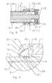
Figure 1 is a schematic isometric rear view of a first exemplary embodiment of a coupling nut mounted on a portion of coaxial cable. -
Figure 2 is a schematic cross-section side view of a coaxial cable ready for insertion into the coupling nut ofFigure 1 . -
Figure 3 is an enlarged close-up schematic cross-section side view of area A ofFigure 2 . -
Figure 4 is an enlarged schematic cross-section side view of a coaxial cable partially inserted into the coupling nut ofFigure 1 . -
Figure 5 is an enlarged close-up schematic cross-section side view of area B ofFigure 4 . -
Figure 6 is an enlarged schematic cross-section side view of a coaxial cable seated within the coupling nut ofFigure 1 . -
Figure 7 is an enlarged close-up schematic cross-section side view of area C ofFigure 6 . -
Figure 8 is a schematic cross-section side view of a coaxial cable under withdrawal tension from the coupling nut ofFigure 1 . -
Figure 9 is an enlarged close-up schematic cross-section side view of area D ofFigure 8 . -
Figure 10 is a schematic isometric view of a snap ring. -
Figure 11 is a schematic side view of a coupling nut with snap ring release apertures, mounted on a portion of cable. -
Figure 12 is a schematic top view of a coupling nut with snap ring release apertures, mounted on a portion of cable. -
Figure 13 is a schematic isometric rear cut-away view of an alternative exemplary embodiment of a coupling nut mounted on a portion of coaxial cable. -
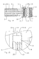
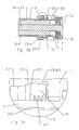
Figure 14 is a schematic cross-section side view of a coaxial cable ready for insertion into the coupling nut ofFigure 13 . -
Figure 15 is an enlarged close-up schematic cross-section side view of area A ofFigure 14 . -
Figure 16 is an enlarged schematic cross-section side view of a coaxial cable partially inserted into the coupling nut ofFigure 13 . -
Figure 17 is an enlarged close-up schematic cross-section side view of area B ofFigure 16 . -
Figure 18 is an enlarged schematic cross-section side view of a coaxial cable seated within the coupling nut ofFigure 13 . -
Figure 19 is an enlarged close-up schematic cross-section side view of area C ofFigure 18 . -
Figure 20 is a schematic cross-section side view of a coaxial cable under withdrawal tension from the coupling nut ofFigure 13 . -
Figure 21 is an enlarged close-up schematic cross-section side view of area D ofFigure 20 . - The inventor has analyzed available coupling nuts and recognized that the rotational interlock between the coupling nut and the coaxial cable created by application of internal threading to the coupling nut that engages the cable jacket often damages the inner conductor. Metal shavings may be generated as the inner conductor repeatedly rotates within the connector body during threading of the coupling nut upon the connector body to clamp the leading edge of the outer conductor. These metal shavings are a source of inter-modulation distortion (IMD), a significant factor of the cable and connector interconnection electrical performance. The threaded engagement between the jacket and the coupling nut adds an additional requirement for precision during cable end preparation and an extra assembly step, the threading of the coupling nut onto the jacket. Further, the threaded interconnection obtained has limited retention strength due to required allowances for the variance observed with respect to the jacket dimensions, especially between cables from different manufacturers.
- As shown in
Figures 1-9 , acoupling nut 1 according to a first exemplary embodiment of the invention eliminates the rotational interlock between thecoupling nut 1 and thejacket 3 and thus thecable 5, while also providing a connection between thejacket 3 andcoupling nut 1 with an increasing retention force as a withdrawal force on thecable 5 is increased, thereby securing and maintaining thecable 5 coaxial with thecoupling nut 1. Thecoupling nut 1 has acylindrical body 7 with abore 9 extending between acable end 11 and aconnector end 13. Depending upon the selected connector interface, thecoupling nut 1 may be provided with athread 10 in thebore 9side wall 17 proximate the connector end 12. - One skilled in the art will appreciate that the
cable end 11 and the connector end 13 and also thecable end 11 side and theconnector end 13 side are descriptors used herein to clarify longitudinal locations and interrelationships between the various elements of thecoupling nut 1. In addition to the identified positions at either end of thebore 9, each individual element has acable end 11 side and aconnector end 13 side, i.e. the sides of the respective element that are facing therespective cable end 11 and theconnector end 13 of thecoupling nut 1. - An
annular wedge groove 15 is formed in thesidewall 17 proximate thecable end 11. Anangled wedge surface 14 of thewedge groove 15, extending from thebore 9sidewall 17 at acable end 11 side to abottom diameter 19 within thewedge groove 15, operates as a guide for asnap ring 21 retained in thewedge groove 15. As thesnap ring 21 moves laterally toward thecable end 11 and engages thewedge surface 14, thesnap ring 21 is redirected radially inward, toward thecable 5. To enhance the mechanical interaction between thesnap ring 21 and thewedge surface 14, thesnap ring 21 may be formed with an angledredirect surface 23 generally parallel and or otherwise complementary to thewedge surface 14, as best shown inFigure 10 . To prevent thesnap ring 21 from binding within thewedge groove 15, prior tocable 5 insertion, thesnap ring 21 may be formed with an outer diameter that is less than thebottom diameter 19. - An
inner surface 25 of thesnap ring 21 has agripping feature 27, for example a plurality of annular barb(s) 29. Thegripping feature 27 may be directional, for example configured to enable thejacket 3 to slide past thegripping feature 27 from thecable end 11 side towards theconnector end 13 side, and to grip thejacket 3 during movement of thejacket 3 from the connector end 11 side towards thecable end 13 side. Where thegripping feature 27 is one or more annular barb(s) 29, the directional characteristic may be achieved by forming the annular barb(s) 29 with an angled surface on thecable end 11 side and a vertical surface on theconnector end 13 side. The annular barbs may be formed in a helical thread configuration, enabling alternative removal of an attachedcoupling nut 1 via unthreading of the annular barb(s) 29 off of thejacket 3. Aramp surface 31 may be formed on thecable end 11 side of thesnap ring 21, operative as a centering guide for theouter conductor 33 of thecable 5 during initial insertion through thesnap ring 21. To minimize costs, thesnap ring 21 may be manufactured from a polymeric material, for example via injection molding. - An inward projecting stop or
shoulder 35 positioned at aconnector end 11 side of thewedge groove 15 may be added as a stop forcable 5 insertion into thebore 9, positioning thecable 5 end laterally for proper engagement with the selected connector body during connector assembly, The inward projectingshoulder 35 may be dimensioned to project inward proximate an outer diameter of theouter conductor 33, thereby, the inward projectingshoulder 35 provides a centering function for thecable 5, maintaining thecable 5 coaxial with thecoupling nut 1, during insertion until the cable end of thejacket 3 abuts the inward projectingshoulder 35. For ease of manufacture via a turning center, the Inward projectingshoulder 35 may be formed as an annular shoulder. - The
coupling nut 1. may be environmentally sealed by the addition of anannular gasket groove 37 preferably located in thesidewall 17 between thewedge groove 15 and the inward projectingshoulder 35. Agasket 39, such as an elastomeric o-ring, seated in thegasket groove 37, is dimensioned to seal against thejacket 3. - In use, the cable end is stripped back to expose desired lengths of the
inner conductor 41 andouter conductor 33 and inserted into thebore 9 of thecoupling nut 1 at the cable end, as best shown inFigures 2 and 3 . As the leading edge of thejacket 3 contacts theramp surface 31 of thesnap ring 21, thesnap ring 21 is pushed toward aconnector end 13 side of thewedge groove 15 and spread radially outward into thewedge groove 15, as best shown inFigures 4 and 5 . When thecable 5 passes far enough into thebore 9, thejacket 3 abuts the inward projectingshoulder 35 as best shown inFigures 6 and 7 . At this point, thesnap ring 21 has a limited range of lateral movement within thewedge groove 15. Thecoupling nut 1 is laterally positioned on the cable end, ready to receive the connector body, thecoupling nut 1 rotatable about the cable end, thesnap ring 21 rotatable within thewedge groove 15. - When a push or pull force is applied to the
cable 5 and or to thecoupling nut 1, moving thecable 5 towards thecable end 11 side with respect to thecoupling nut 1, thegripping feature 27 engages thejacket 3 and pulls thesnap ring 21 into thewedge surface 14, which operates to drive thesnap ring 21 radially inward into a progressively increasing secure centering contact with thejacket 3 thus preventingfurther cable 5 movement with respect to thecoupling nut 1, as best shown inFigures 8 and 9 . - To release a
coupling nut 1 from acable 5, a shim may be inserted between theramp surface 31 and thejacket 3, to drive thesnap ring 21 towards theconnector end 13 and radially outward, free of engagement with thejacket 3. Alternatively, thecoupling nut 1 may be configured with aperture(s) 43 between the outer diameter of thecoupling nut 1 and thewedge groove 15, for example as shown inFigures 1 ,11 and 12 . The aperture(s) 43 may be formed as slots that intersect with thewedge groove 15. Pushing thesnap ring 21 towards theconnector end 13 side of thewedge groove 15 via the aperture(s) 43 disengages thesnap ring 21 from thewedge surface 14 and thereby thesnap ring 21 from thejacket 3, enabling withdrawal of thecable 5 from thecoupling nut 1. - In an alternative embodiment, as shown in
figures 13-21 , thewedge groove 15 may be formed with an insertion seat 45 at thebottom diameter 19 and a retainingseat 47 at thecable end 11 side of thewedge surface 14. Thesnap ring 21 is provided with an outer diameter surface complementary to the insertion seat 45 and the retainingseat 47. Theredirect surface 23 of thesnap ring 21, may be formed as a rounded edge. - As shown in
Figures 14 and 15 , the insertion seat 45 provides a space for thesnap ring 21 prior tocable 5 insertion. Duringcable 5 insertion (Figures 16 and 17 ), thesnap ring 21 spreads further into the insertion seat 45, enabling thesnap ring 21 to spread and pass over thejacket 3. - When a push or pull force is applied to the
cable 5 and or to thecoupling nut 1, moving thecable 5 towards thecable end 11 side with respect to thecoupling nut 1, thegripping feature 27 engages thejacket 3 and pulls thesnap ring 21, stabilized by the insertion seat 45, into the wedge surface 14 (Figures 18 and 19 ), which operates to drive thesnap ring 21 radially inward into a progressively increasing secure centering contact with thejacket 3 until thesnap ring 21 finally seats within the retainingseat 47, held against thecable 5, as best shown inFigures 20 and 21 . - Although application of the retaining
seat 47 increases a length requirement of thecoupling nut 1, the retainingseat 47 increases the stability of thecoupling nut 1 upon thecable 5 compared to the first embodiment, as engagement between thewedge surface 14 and thesnap ring 21 in the installed position that biases thecoupling nut 1 to move towards thecable end 11 side with respect to thesnap ring 21 is eliminated. - One skilled in the art will appreciate the several improvements realized via the present invention. The
coupling nut 1 is usable with a wide range of different cable(s) 5 having jacket(s) 3 of varying thickness and or surface characteristics. Because thecoupling nut 1 is rotatable with respect to thecable 5 during connector assembly, generation of metal shavings at the inner conductor spring basket and or other degradation of theinner conductor 41 from rotation of the spring basket about theinner conductor 41 is eliminated. The prior complex internal jacket thread machining operations are eliminated. The prior threaded mounting operation between thejacket 3 and thecoupling nut 1 is eliminated. The space available for thegasket 39 is increased and a travel distance of thegasket 39 across thejacket 3 is reduced, enabling use of awider gasket 39 with greater contact area against thejacket 3, improving the environmental seal. Thecable 5 is held more securely with respect to thecoupling nut 1, improving thecable 5 to connector interconnection strength. Thecable 5 is supported coaxially within thecoupling nut 1 at two spaced apart points, reducing the opportunity for the cable to shift and generate IMD, Further, the compact but more securely supported configuration enables compact angled connector configurations, such as right angle connectors, panel mount connectors and the like. Finally, installation is greatly simplified, eliminating the previous need for tools to grip thecoupling nut 1 for threading upon thejacket 3.Table of Parts 1 coupling nut 3 jacket 5 cable 7 body 9 bore 10 thread 11 cable end 13 connector end 14 wedge surface 15 wedge groove 17 side wall 19 bottom diameter 21 snap ring 23 redirect surface 25 inner surface 27 gripping feature 29 annular barb 31 ramp surface 33 outer conductor 35 shoulder 37 gasket groove 39 gasket 41 inner conductor 43 aperture 45 insertion seat 47 retaining seat - Where in the foregoing description reference has been made to materials, ratios, integers or components having known equivalents then such equivalents are herein incorporated as if individually set forth.
- While the present invention has been illustrated by the description of the embodiments thereof, and while the embodiments have been described in considerable detail, it is not the intention of the applicant to restrict or in any way limit the scope of the appended claims to such detail Additional advantages and modifications will readily appear to those skilled in the art. Therefore, the invention in its broader aspects is not limited to the specific details, representative apparatus, methods, and illustrative examples shown and described. Accordingly, departures may be made from such details without departure from the spirit or scope of applicant's general inventive concept. Further, it is to be appreciated that improvements and/or modifications may be made thereto without departing from the scope or spirit of the present invention as defined by the following claims.
Claims (20)
- A coupling nut for an electrical connector connectable to an electrical cable having an outer conductor surrounded by a jacket, comprising:a cylindrical body with a bore extending between a cable end and a connector end;an annular wedge groove;an angled wedge surface in a sidewall of the bore proximate the cable end extending from the bore sidewall at a cable end side to a bottom diameter within the wedge groove;a snap ring retained in the wedge groove; andan inner surface of the snap ring provided with a gripping feature.
- The coupling nut of claim 1, further including a radially inward projecting shoulder positioned at a connector end side of the wedge groove.
- The coupling nut of claim 2, wherein the inward projecting shoulder projects inward proximate an outer diameter of the outer conductor.
- The coupling nut of claim 2, further including an annular gasket groove in the bore sidewall between the wedge groove and the inward projecting shoulder.
- The coupling nut of claim 5, further including a gasket seated in the gasket groove; the gasket dimensioned to seal against the jacket.
- The coupling nut of claim 1, wherein the snap ring has a radially outer angled surface parallel to the wedge surface.
- The coupling nut of claim 1, wherein the gripping feature is dimensioned to enable the jacket to slide past the gripping feature from the cable end towards the connector end, and to grip the jacket during movement of the jacket from the connector end towards the cable end.
- The coupling nut of claim 1, wherein the gripping feature is a plurality of annular barbs.
- The coupling nut of claim 8, wherein the annular barbs are angled to pass over the jacket as the jacket is inserted into the bore from the cable end and to grip the jacket as it is removed towards the cable end.
- The coupling nut of claim 8, wherein the annular barbs are formed as a helical thread.
- The coupling nut of claim 1, further including at least one aperture between the outer surface of the coupling nut 1 and the wedge groove.
- The coupling nut of claim 1, further including a thread in the bore sidewall at the connector end.
- The coupling nut of claim 1, wherein the snap ring has an outer diameter annular ramp surface at a cable end side.
- The coupling nut of claim 1, wherein the bottom diameter is greater than an outer diameter of the snap ring.
- The coupling nut of claim 1, further including an insertion seat at the bottom diameter.
- The coupling nut of claim 1, further including a retaining seat at a cable end side of the angled wedge surface.
- A coupling nut for an electrical connector connectable to an electrical cable having an outer conductor surrounded by a jacket, comprising:a cylindrical body with a bore extending between a cable end and a connector end;an annular wedge groove in the bore sidewall proximate the cable end;an angled wedge surface of the wedge groove extending from the bore sidewall at a cable end side to a bottom diameter within the wedge groove;a snap ring retained in the wedge groove;the snap ring has an outer angled surface parallel to the wedge surface;an inner surface of the snap ring provided with a a plurality of annular barbs;an annular inward projecting shoulder positioned at a connector end side of the wedge groove, projecting inward proximate an outer diameter of the outer conductor;an annular gasket groove in the bore sidewall between the wedge groove and the inward projecting shoulder; anda gasket seated in the gasket groove; the gasket dimensioned to seal against the jacket.
- A coupling nut for an electrical connector connectable to an electrical cable having an outer conductor surrounded by a jacket, comprising:a cylindrical body with a bore extending between a cable end and a connector end;an annular wedge groove in a sidewall of the bore; the wedge groove provided with an angled wedge surface proximate the cable end extending from a retaining seat at a cable end side to an insertion seat at a bottom diameter;a snap ring retained in the wedge groove; andan inner surface of the snap ring provided with a gripping feature.
- The coupling nut of claim 18, wherein the retaining seat and snap ring are dimensioned such that the gripping feature of the snap ring engages the jacket when the snap ring is seated in the retaining seat.
- The coupling nut of claim 18, wherein the snap ring has an outer surface parallel to the retaining seat.
Applications Claiming Priority (1)
| Application Number | Priority Date | Filing Date | Title |
|---|---|---|---|
| US12/164,854 US7824214B2 (en) | 2008-06-30 | 2008-06-30 | Coupling nut with cable jacket retention |
Publications (2)
| Publication Number | Publication Date |
|---|---|
| EP2146396A2 true EP2146396A2 (en) | 2010-01-20 |
| EP2146396A3 EP2146396A3 (en) | 2014-06-11 |
Family
ID=41129297
Family Applications (1)
| Application Number | Title | Priority Date | Filing Date |
|---|---|---|---|
| EP09008395.7A Withdrawn EP2146396A3 (en) | 2008-06-30 | 2009-06-26 | Coupling nut with cable jacket retention |
Country Status (4)
| Country | Link |
|---|---|
| US (1) | US7824214B2 (en) |
| EP (1) | EP2146396A3 (en) |
| JP (1) | JP2010015988A (en) |
| CN (1) | CN101714709A (en) |
Cited By (2)
| Publication number | Priority date | Publication date | Assignee | Title |
|---|---|---|---|---|
| GB2504734A (en) * | 2012-08-08 | 2014-02-12 | Technetix Bv | Male F-connector with electromagnetic screening |
| GB2563901B (en) * | 2017-06-29 | 2022-08-10 | Technetix Bv | Coaxial cable connector |
Families Citing this family (18)
| Publication number | Priority date | Publication date | Assignee | Title |
|---|---|---|---|---|
| US7927134B2 (en) * | 2008-11-05 | 2011-04-19 | Andrew Llc | Coaxial connector for cable with a solid outer conductor |
| US8454383B2 (en) * | 2008-11-05 | 2013-06-04 | Andrew Llc | Self gauging insertion coupling coaxial connector |
| US8449327B2 (en) * | 2008-11-05 | 2013-05-28 | Andrew Llc | Interleaved outer conductor spring contact for a coaxial connector |
| US7806724B2 (en) * | 2008-11-05 | 2010-10-05 | Andrew Llc | Coaxial connector for cable with a solid outer conductor |
| US8277247B2 (en) * | 2008-11-05 | 2012-10-02 | Andrew Llc | Shielded grip ring for coaxial connector |
| US8460031B2 (en) * | 2008-11-05 | 2013-06-11 | Andrew Llc | Coaxial connector with cable diameter adapting seal assembly and interconnection method |
| US8136234B2 (en) * | 2008-11-24 | 2012-03-20 | Andrew Llc | Flaring coaxial cable end preparation tool and associated methods |
| US7931499B2 (en) | 2009-01-28 | 2011-04-26 | Andrew Llc | Connector including flexible fingers and associated methods |
| US9006570B2 (en) * | 2012-11-08 | 2015-04-14 | General Electric Company | Sealing between an electrical cable and a flexible metal conduit to be used in a high temperature, high vibration environment |
| BR112016015026A2 (en) | 2013-12-24 | 2017-08-08 | Ppc Broadband Inc | A CONNECTOR THAT HAS AN INTERNAL CONDUCTOR ENGAGEMENT |
| BR112017001928A2 (en) | 2014-07-30 | 2017-11-28 | Corning Optical Comm Rf Llc | ? coaxial cable connectors with conductive retaining elements? |
| ES2584540B1 (en) | 2015-03-27 | 2017-07-05 | Te Connectivity Amp España, S.L.U. | Latch for telecommunications connector |
| CN105281151A (en) * | 2015-10-14 | 2016-01-27 | 江苏荣联科技发展股份有限公司 | Fixing structure of coaxial connector nut |
| CN107069317A (en) * | 2017-05-26 | 2017-08-18 | 中兴通讯股份有限公司 | A kind of water proof and dust proof sealing shroud suitable for different profile connectors |
| US10079447B1 (en) * | 2017-07-21 | 2018-09-18 | Pct International, Inc. | Coaxial cable connector with an expandable pawl |
| EP4005032A4 (en) * | 2019-07-22 | 2023-07-26 | CommScope Technologies LLC | CAP ASSEMBLY FOR CONNECTOR ASSEMBLY |
| CN111101885A (en) * | 2019-12-31 | 2020-05-05 | 中国石油天然气股份有限公司 | Underground flexible continuous composite pipe connecting joint with cable preset on inner wall and method |
| US11336049B1 (en) | 2020-10-30 | 2022-05-17 | Amphenol Corporation | Sealed electrical connector and method of sealing |
Citations (2)
| Publication number | Priority date | Publication date | Assignee | Title |
|---|---|---|---|---|
| US5795188A (en) | 1996-03-28 | 1998-08-18 | Andrew Corporation | Connector kit for a coaxial cable, method of attachment and the resulting assembly |
| US7335059B2 (en) | 2006-03-08 | 2008-02-26 | Commscope, Inc. Of North Carolina | Coaxial connector including clamping ramps and associated method |
Family Cites Families (17)
| Publication number | Priority date | Publication date | Assignee | Title |
|---|---|---|---|---|
| US3103548A (en) | 1961-11-16 | 1963-09-10 | Crimped coaxial cable termination | |
| US3184706A (en) * | 1962-09-27 | 1965-05-18 | Itt | Coaxial cable connector with internal crimping structure |
| GB1348806A (en) | 1971-05-20 | 1974-03-27 | C S Antennas Ltd | Coaxial connectors |
| JPS5338138Y2 (en) * | 1973-07-20 | 1978-09-14 | ||
| US4557546A (en) | 1983-08-18 | 1985-12-10 | Sealectro Corporation | Solderless coaxial connector |
| EP0167738A3 (en) * | 1984-06-04 | 1987-07-22 | Allied Corporation | Electrical connector having means for retaining a coaxial cable |
| JP3059122U (en) * | 1998-11-16 | 1999-07-02 | 株式会社七星科学研究所 | Cable holding device in coaxial connector |
| JP3075662U (en) * | 2000-08-15 | 2001-02-27 | 明華 葉 | IDC type coaxial cable connector |
| US6846988B2 (en) * | 2002-01-18 | 2005-01-25 | Adc Telecommunications, Inc. | Triaxial connector including cable clamp |
| JP4283555B2 (en) * | 2003-02-07 | 2009-06-24 | 日本アンテナ株式会社 | Coaxial connector |
| US7390027B2 (en) * | 2003-08-13 | 2008-06-24 | Bridgeport Fittings, Inc. | Weatherproof compression connecting assembly for securing electrical metal tubing |
| US7011546B2 (en) | 2003-09-09 | 2006-03-14 | Commscope Properties, Llc | Coaxial connector with enhanced insulator member and associated methods |
| US6776657B1 (en) * | 2003-11-13 | 2004-08-17 | Chen-Hung Hung | Connector capable of connecting to coaxial cable without using tool |
| US7347727B2 (en) * | 2004-01-23 | 2008-03-25 | Andrew Corporation | Push-on connector interface |
| US7018235B1 (en) * | 2004-12-14 | 2006-03-28 | Corning Gilbert Inc. | Coaxial cable connector |
| US7207838B2 (en) * | 2004-12-30 | 2007-04-24 | See Sprl | Coaxial connectors |
| US7588460B2 (en) * | 2007-04-17 | 2009-09-15 | Thomas & Betts International, Inc. | Coaxial cable connector with gripping ferrule |
-
2008
- 2008-06-30 US US12/164,854 patent/US7824214B2/en not_active Expired - Fee Related
-
2009
- 2009-06-26 EP EP09008395.7A patent/EP2146396A3/en not_active Withdrawn
- 2009-06-30 CN CN200910303889A patent/CN101714709A/en active Pending
- 2009-06-30 JP JP2009156218A patent/JP2010015988A/en active Pending
Patent Citations (2)
| Publication number | Priority date | Publication date | Assignee | Title |
|---|---|---|---|---|
| US5795188A (en) | 1996-03-28 | 1998-08-18 | Andrew Corporation | Connector kit for a coaxial cable, method of attachment and the resulting assembly |
| US7335059B2 (en) | 2006-03-08 | 2008-02-26 | Commscope, Inc. Of North Carolina | Coaxial connector including clamping ramps and associated method |
Cited By (2)
| Publication number | Priority date | Publication date | Assignee | Title |
|---|---|---|---|---|
| GB2504734A (en) * | 2012-08-08 | 2014-02-12 | Technetix Bv | Male F-connector with electromagnetic screening |
| GB2563901B (en) * | 2017-06-29 | 2022-08-10 | Technetix Bv | Coaxial cable connector |
Also Published As
| Publication number | Publication date |
|---|---|
| US7824214B2 (en) | 2010-11-02 |
| EP2146396A3 (en) | 2014-06-11 |
| CN101714709A (en) | 2010-05-26 |
| US20090325420A1 (en) | 2009-12-31 |
| JP2010015988A (en) | 2010-01-21 |
Similar Documents
| Publication | Publication Date | Title |
|---|---|---|
| US7824214B2 (en) | Coupling nut with cable jacket retention | |
| CN1122331C (en) | Connectors and how to operate them | |
| US7727013B1 (en) | Low PIM rotatable connector | |
| EP1956687A2 (en) | Annular corrugated coaxial cable connector with polymeric spring finger nut | |
| US8454383B2 (en) | Self gauging insertion coupling coaxial connector | |
| AU2005275374B2 (en) | Compression connector for coaxial cable | |
| US7824215B2 (en) | Axial compression coaxial connector with grip surfaces | |
| US7048579B2 (en) | Compression connector for coaxial cable | |
| US7357671B2 (en) | Coaxial plug-type connector and method for mounting the same | |
| US7927134B2 (en) | Coaxial connector for cable with a solid outer conductor | |
| US7131868B2 (en) | Compression connector for coaxial cable | |
| US6793529B1 (en) | Coaxial connector with positive stop clamping nut attachment | |
| US7918687B2 (en) | Coaxial connector grip ring having an anti-rotation feature | |
| US7607942B1 (en) | Multi-shot coaxial connector and method of manufacture | |
| US7806724B2 (en) | Coaxial connector for cable with a solid outer conductor | |
| US20070224880A1 (en) | Axial Compression Electrical Connector for Annular Corrugated Coaxial Cable | |
| US7736180B1 (en) | Inner conductor wedge attachment coupling coaxial connector | |
| WO2011053438A1 (en) | Shielded grip ring for coaxial connector | |
| AU2010313683A1 (en) | Self gauging insertion coupling coaxial connector |
Legal Events
| Date | Code | Title | Description |
|---|---|---|---|
| PUAI | Public reference made under article 153(3) epc to a published international application that has entered the european phase |
Free format text: ORIGINAL CODE: 0009012 |
|
| AK | Designated contracting states |
Kind code of ref document: A2 Designated state(s): AT BE BG CH CY CZ DE DK EE ES FI FR GB GR HR HU IE IS IT LI LT LU LV MC MK MT NL NO PL PT RO SE SI SK TR |
|
| AX | Request for extension of the european patent |
Extension state: AL BA RS |
|
| PUAL | Search report despatched |
Free format text: ORIGINAL CODE: 0009013 |
|
| RIC1 | Information provided on ipc code assigned before grant |
Ipc: H01R 13/622 20060101ALI20140430BHEP Ipc: H01R 4/50 20060101ALI20140430BHEP Ipc: H01R 9/05 20060101AFI20140430BHEP |
|
| AK | Designated contracting states |
Kind code of ref document: A3 Designated state(s): AT BE BG CH CY CZ DE DK EE ES FI FR GB GR HR HU IE IS IT LI LT LU LV MC MK MT NL NO PL PT RO SE SI SK TR |
|
| AX | Request for extension of the european patent |
Extension state: AL BA RS |
|
| STAA | Information on the status of an ep patent application or granted ep patent |
Free format text: STATUS: THE APPLICATION IS DEEMED TO BE WITHDRAWN |
|
| 18D | Application deemed to be withdrawn |
Effective date: 20141212 |