EP2146349A2 - Nuclear reactor components including material layers to reduce enhanced corrosion on zirconium alloys used in fuel assemblies and methods thereof - Google Patents
Nuclear reactor components including material layers to reduce enhanced corrosion on zirconium alloys used in fuel assemblies and methods thereof Download PDFInfo
- Publication number
- EP2146349A2 EP2146349A2 EP09164969A EP09164969A EP2146349A2 EP 2146349 A2 EP2146349 A2 EP 2146349A2 EP 09164969 A EP09164969 A EP 09164969A EP 09164969 A EP09164969 A EP 09164969A EP 2146349 A2 EP2146349 A2 EP 2146349A2
- Authority
- EP
- European Patent Office
- Prior art keywords
- component
- alloys
- material layer
- nuclear reactor
- zirconium
- Prior art date
- Legal status (The legal status is an assumption and is not a legal conclusion. Google has not performed a legal analysis and makes no representation as to the accuracy of the status listed.)
- Granted
Links
Images


Classifications
-
- G—PHYSICS
- G21—NUCLEAR PHYSICS; NUCLEAR ENGINEERING
- G21C—NUCLEAR REACTORS
- G21C17/00—Monitoring; Testing ; Maintaining
- G21C17/02—Devices or arrangements for monitoring coolant or moderator
- G21C17/022—Devices or arrangements for monitoring coolant or moderator for monitoring liquid coolants or moderators
- G21C17/0225—Chemical surface treatment, e.g. corrosion
-
- G—PHYSICS
- G21—NUCLEAR PHYSICS; NUCLEAR ENGINEERING
- G21C—NUCLEAR REACTORS
- G21C21/00—Apparatus or processes specially adapted to the manufacture of reactors or parts thereof
- G21C21/02—Manufacture of fuel elements or breeder elements contained in non-active casings
-
- G—PHYSICS
- G21—NUCLEAR PHYSICS; NUCLEAR ENGINEERING
- G21C—NUCLEAR REACTORS
- G21C3/00—Reactor fuel elements and their assemblies; Selection of substances for use as reactor fuel elements
- G21C3/30—Assemblies of a number of fuel elements in the form of a rigid unit
- G21C3/32—Bundles of parallel pin-, rod-, or tube-shaped fuel elements
- G21C3/34—Spacer grids
- G21C3/356—Spacer grids being provided with fuel element supporting members
-
- Y—GENERAL TAGGING OF NEW TECHNOLOGICAL DEVELOPMENTS; GENERAL TAGGING OF CROSS-SECTIONAL TECHNOLOGIES SPANNING OVER SEVERAL SECTIONS OF THE IPC; TECHNICAL SUBJECTS COVERED BY FORMER USPC CROSS-REFERENCE ART COLLECTIONS [XRACs] AND DIGESTS
- Y02—TECHNOLOGIES OR APPLICATIONS FOR MITIGATION OR ADAPTATION AGAINST CLIMATE CHANGE
- Y02E—REDUCTION OF GREENHOUSE GAS [GHG] EMISSIONS, RELATED TO ENERGY GENERATION, TRANSMISSION OR DISTRIBUTION
- Y02E30/00—Energy generation of nuclear origin
- Y02E30/30—Nuclear fission reactors
Definitions
- Example embodiments generally relate to nuclear reactors including components that have reduced shadow corrosion on zirconium alloys and methods thereof.
- nuclear power plants include a reactor core having fuel arranged therein to produce power by nuclear fission.
- a common design in nuclear power plants is to arrange fuel in a plurality of fuel rods bound together as a fuel assembly, or fuel bundle, placed within the reactor core.
- These fuel rods typically include several elements joining the fuel rods to assembly components at various axial locations throughout the assembly.
- a conventional fuel bundle 10 of a nuclear reactor such as a BWR
- a nuclear reactor such as a BWR
- a plurality of full-length fuel rods 18 and/or partial length fuel rods 19 may be arranged in a matrix within the fuel bundle 10 and pass through a plurality of spacers 20.
- Fuel rods 18 and 19 generally originate and terminate at upper and lower tie plates 14 and 16, continuously running the length of the fuel bundle 10, with the exception of partial length rods 19, which all terminate at a lower vertical position from the full length rods 18.
- FIG. 1B illustrates a conventional BWR 75, including four fuel assemblies 10 and a control blade 15.
- Corrosion is commonly observed on e.g., channel 12 made of Zircaloys when, for example, a control blade 15, constructed with a stainless steel outer casing, is placed close to the channel 12.
- Zircaloys are well known high zirconium alloys commonly used in nuclear reactors. Corrosion may also be found on Zircaloy fuel cladding in contact with or close to nuclear components made from nickel and/or iron based alloys, e.g., a spacer 20 or spacer spring (not shown).
- the corrosion also known as "shadow” corrosion, weakens the Zircaloy components and decreases the components useful lifespan.
- Example embodiments are directed to providing a thin, adherent coating on the surfaces of nuclear reactor components that are known to cause increased corrosion on adjacent zirconium alloy structures and methods of reducing the increased corrosion.
- Example embodiments include coatings structurally bonded to components such that the difference in the corrosion potential between a coated component and a zirconium alloy component is less than that between a component without the coating and the zirconium alloy component.
- Example embodiments include nuclear reactors comprising a first component formed of at least one material selected from nickel based alloys and iron based alloys, and a second component adjacent to the first component.
- the second component is formed of a zirconium alloy.
- a material layer is formed on at least one surface of the first component.
- the material layer is formed of a different material than the first component such that a difference in electrochemical corrosion potential between the first component and the second component is reduced.
- Example embodiments also include methods of enhancing zirconium corrosion resistance in a nuclear reactor fuel assembly by forming a material layer on at least one surface of a first component adjacent to a second component, such that a difference in electrochemical potential between the first component and the second component is reduced.
- first, second, third etc. may be used herein to describe various elements, components, regions, layers and/or sections, these elements, components, regions, layers and/or sections should not be limited by these terms. These terms are only used to distinguish one element, component, region, layer or section from another region, layer or section. Thus, a first element, component, region, layer or section discussed below could be termed a second element, component, region, layer or section without departing from the scope of example embodiments.
- spatially relative terms e.g. "beneath,” “below,” “lower,” “above,” “upper” and the like, may be used herein for ease of description to describe one element or a relationship between a feature and another element or feature as illustrated in the figures. It will be understood that the spatially relative terms are intended to encompass different orientations of the device in use or operation in addition to the orientation depicted in the Figures. For example, if the device in the figures is turned over, elements described as “below” or “beneath” other elements or features would then be oriented “above” the other elements or features. Thus, for example, the term “below” can encompass both an orientation which is above as well as below. The device may be otherwise oriented (rotated 90 degrees or viewed or referenced at other orientations) and the spatially relative descriptors used herein should be interpreted accordingly.
- Example embodiments are described herein with reference to cross-sectional illustrations that are schematic illustrations of idealized embodiments (and intermediate structures). As such, variations from the shapes of the illustrations as a result, for example, of manufacturing techniques and/or tolerances, may be expected. Thus, example embodiments should not be construed as limited to the particular shapes of regions illustrated herein but may include deviations in shapes that result, for example, from manufacturing. For example, an implanted region illustrated as a rectangle may have rounded or curved features and/or a gradient ( e . g ., of implant concentration) at its edges rather than an abrupt change from an implanted region to a non-implanted region.
- a gradient e . g ., of implant concentration
- a buried region formed by implantation may result in some implantation in the region between the buried region and the surface through which the implantation may take place.
- the regions illustrated in the figures are schematic in nature and their shapes do not necessarily illustrate the actual shape of a region of a device and do not limit the scope.
- Example embodiments will now be described more fully with reference to the accompanying drawings, in which exemplary embodiments of the invention are shown.
- the example embodiments may, however, be embodied in many different forms and should not be construed as being limited to the embodiments set forth herein. Rather, these embodiments are provided so that this disclosure will be thorough and complete, and will fully convey the scope of the invention to one of ordinary skill in the art.
- the sizes of constitutional elements may be exaggerated for convenience of illustration.
- Example embodiments are directed to reducing the shadow-forming tendency of nuclear reactor components formed of, nickel alloys (e.g., INCONEL), iron alloys (e.g., stainless steels), etc., by using a thin coating to reduce the difference in electrochemical potential between the component and any adjacent and/or nearby zirconium alloy based components to thereby reduce the formation of shadow corrosion on the zirconium alloy.
- the nuclear reactor components may include, parts of a fuel assembly, for example, spacers, spacer springs, tie plates, control blades, etc.
- adjacent and nearby are to be construed broadly as including, e.g., the at least two components being directly in contact with each other, to the at least the two components being within the same reactor.
- a nuclear reactor component for example, a spacer 20 has a material layer 300 formed on a surface thereof.
- the material layer 300 is stable in various nuclear reactor environments, e.g., BWR reactors, and does not crack and/or spall during nuclear processing.
- Material layer 300 may be any material that when formed on nuclear component 20 reduces the difference between the electrochemical corrosion potential of the nuclear component 20 and at least one adjacent zirconium alloy component.
- Such materials for the material layer 300 may include, titanium, zirconium, hafnium, yttrium, scandium, alloys and oxides thereof, etc., (e.g., Zircaloy-2 with 0.25% iron (GNF-Ziron), High Fe-Ni Zircaloy, Zr-Sn-Fe-Cr alloy (VB)), and any other similar materials, which would be converted to an oxide by in-reactor corrosion.
- GNF-Ziron is further described in U.S. Patent No. 4,810,461 , which is hereby incorporated in its entirety by reference and VB is further described in U.S. Patent No. 5,712,888 , which is hereby incorporated in its entirety by reference.
- the various oxides are effective because the oxides achieve a similar electrochemical corrosion potential as the adjacent zirconium alloy component.
- the adjacent zirconium alloy component may include, e.g., Zircaloy-2, Zircaoly-4, Zr-Sn alloys, Zr-Sn-Fe-Cr-Ni alloys, Zr-Nb alloys, etc.
- the material layer 300 may be deposited by various well known methods.
- material layer 300 may be formed using chemical vapor deposition (CVD), plasma vapor deposition (PVD), plasma enhanced chemical vapor deposition (PECVD), plasma thermal spraying, high-velocity oxy-fuel (HVOF) thermal spraying, wire arcing, electroless deposition, and/or electroplating.
- CVD chemical vapor deposition
- PVD plasma vapor deposition
- PECVD plasma enhanced chemical vapor deposition
- plasma thermal spraying high-velocity oxy-fuel (HVOF) thermal spraying, wire arcing, electroless deposition, and/or electroplating.
- HVOF high-velocity oxy-fuel
- the material layer 300 may be formed using ion implantation, including, for example, at least one ion source including zirconium, titanium, hafnium, and/or scandium.
- the material layer 300 may be thin, e.g., generally about 25 microns or less. By using a thin material layer 300, coolant flow through and/or around the component 20 is not significantly affected by the presence of the material layer 300.
- a buffer layer 310 may be formed between the nuclear component 20 and the material layer 300.
- Buffer layer 310 may increase the adhesion between the material layer 300 and the component 20 and may be formed from tantalum, its oxides, and alloys.
- the buffer layer 310 may be formed using similar methods as discussed above with reference to material layer 300 and the combination of material layer 300 and buffer layer 310 may also be about 25 microns or less.
- Figure 3 shows a graph of the electrochemical corrosion potential (ECP) behavior of 304 SS, Zircaloy-2 and pure Zr as a function of oxygen concentration in 288°C water.
- pure Zr has the lowest potential, approximately -850 mV
- Zircaloy-2 is in the middle, ranging from approximately -600 to -200 mV
- 304 SS has the highest potential ranging from approximately -400 to 200 mV.
- Nickel-based alloys such as INCOLNEL 600, INCONEL X750, etc., show similar ECP behavior as 304 SS in high temperature water.
- the electrochemical corrosion potential of 304 SS may be reduced by forming a Zircaloy-2 layer on the surface thereof.
- the coated 304 SS shows a decrease in potential from approximately -400 to 200 mV (shown in FIG. 3 ) to approximately -470 to -380 mV (shown in FIG. 5 ) depending on the oxygen concentration.
- the ECP decreased and the difference between the coated 304 SS component and an adjacent Zircaloy-2 component would also decrease thereby reducing the corrosion of the Zircaloy-2 component (shown in FIG. 4 ).
- Zr-based alloys e.g., Zircaloy 2
- Fe-based alloy e.g., 304 SS
- Ni-based alloy e.g., Alloy X750
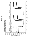
- FIG. 5 further illustrates the decrease in the ECP difference between a non-zirconium alloy component coated with a thin material layer and a zirconium alloy component, by showing a comparison of the corrosion potential behavior.
- FIG. 5 illustrates the corrosion potential behavior of a TiO2 coated Fe-Cr-Ni alloy component (produced by CVD) and a zirconium alloy component with and without UV illumination in 0.01M Na 2 SO 4 solution at 25°C. The UV illumination is used to simulate in reactor processing. For the experiment illustrated, both components were pre-oxidized in 300°C water containing 500 ppb 02 before the UV illumination.
- the electrically non-conducting oxide film prevents and/or greatly restricts mass transport of oxidants to the component's metal surface causing the ECP to shift to a low value even at high oxidants levels during UV illumination.
- example embodiment fuel assembly components may be inserted into BWR-type fuel rods and fuel bundles in example embodiments, it is understood that other types of fuel and power plants may be useable with example embodiment retention devices.
- PWR, CANDU, RBMK, ESBWR, etc. type reactors may include fuel rods that can accommodate example embodiment retention devices in order to irradiate irradiation targets therein.
- example embodiments may be varied through routine experimentation and without further inventive activity.
- other fuel types, shapes, and configurations may be used in conjunction with example embodiment fuel bundles and tie plate attachments.
- Variations are not to be regarded as departure from the spirit and scope of the exemplary embodiments, and all such modifications as would be obvious to one skilled in the art are intended to be included within the scope of the following claims.
Landscapes
- Engineering & Computer Science (AREA)
- Physics & Mathematics (AREA)
- Plasma & Fusion (AREA)
- General Engineering & Computer Science (AREA)
- High Energy & Nuclear Physics (AREA)
- Manufacturing & Machinery (AREA)
- Other Surface Treatments For Metallic Materials (AREA)
- Physical Vapour Deposition (AREA)
Abstract
Description
- Example embodiments generally relate to nuclear reactors including components that have reduced shadow corrosion on zirconium alloys and methods thereof.
- Generally, nuclear power plants include a reactor core having fuel arranged therein to produce power by nuclear fission. A common design in nuclear power plants is to arrange fuel in a plurality of fuel rods bound together as a fuel assembly, or fuel bundle, placed within the reactor core. These fuel rods typically include several elements joining the fuel rods to assembly components at various axial locations throughout the assembly.
- As shown in
FIG. 1A , aconventional fuel bundle 10 of a nuclear reactor, such as a BWR, may include anouter channel 12 surrounding anupper tie plate 14 and alower tie plate 16. A plurality of full-length fuel rods 18 and/or partiallength fuel rods 19 may be arranged in a matrix within thefuel bundle 10 and pass through a plurality ofspacers 20.Fuel rods lower tie plates fuel bundle 10, with the exception ofpartial length rods 19, which all terminate at a lower vertical position from thefull length rods 18.FIG. 1B illustrates a conventional BWR 75, including fourfuel assemblies 10 and a control blade 15. - Corrosion is commonly observed on e.g.,
channel 12 made of Zircaloys when, for example, a control blade 15, constructed with a stainless steel outer casing, is placed close to thechannel 12. Zircaloys are well known high zirconium alloys commonly used in nuclear reactors. Corrosion may also be found on Zircaloy fuel cladding in contact with or close to nuclear components made from nickel and/or iron based alloys, e.g., aspacer 20 or spacer spring (not shown). The corrosion, also known as "shadow" corrosion, weakens the Zircaloy components and decreases the components useful lifespan. - Example embodiments are directed to providing a thin, adherent coating on the surfaces of nuclear reactor components that are known to cause increased corrosion on adjacent zirconium alloy structures and methods of reducing the increased corrosion. Example embodiments include coatings structurally bonded to components such that the difference in the corrosion potential between a coated component and a zirconium alloy component is less than that between a component without the coating and the zirconium alloy component.
- Example embodiments include nuclear reactors comprising a first component formed of at least one material selected from nickel based alloys and iron based alloys, and a second component adjacent to the first component. The second component is formed of a zirconium alloy. A material layer is formed on at least one surface of the first component. The material layer is formed of a different material than the first component such that a difference in electrochemical corrosion potential between the first component and the second component is reduced.
- Example embodiments also include methods of enhancing zirconium corrosion resistance in a nuclear reactor fuel assembly by forming a material layer on at least one surface of a first component adjacent to a second component, such that a difference in electrochemical potential between the first component and the second component is reduced.
- Example embodiments will become more apparent by describing, in detail, the attached drawings, wherein like elements are represented by like reference numerals, which are given by way of illustration only and thus do not limit the example embodiments herein.
-
FIG. 1A is an illustration of a conventional art fuel assembly. -
FIG. 1B is an illustration of a conventional BWR including four fuel assemblies and a control blade. -
FIG. 2A is a cross section of a surface of a nuclear reactor component having a thin material layer thereon according to example embodiments. -
FIG. 2B is a cross section of a surface of a nuclear reactor component having a thin material layer and a buffer layer thereon according to example embodiments. -
FIG. 3 is a graph of electrochemical corrosion potential vs. oxygen concentration for 304 SS, Zircaloy-2, and pure zirconium. -
FIG. 4 is a graph of electrochemical corrosion potential vs. immersion time of a Zircaloy-2 coated 304 SS electrode. -
FIG. 5 is a graph illustrating the results of an experiment showing a comparison of corrosion potential vs. immersion time of TiO2 coated Fe-Cr-Ni alloy and zirconium alloy using UV to simulate the radiation experienced during nuclear processing. - Various example embodiments will now be described more fully with reference to the accompanying drawings in which some example embodiments are illustrated. In the drawings, the thicknesses of layers and regions may be exaggerated for clarity.
- Detailed illustrative embodiments are disclosed herein. However, specific structural and functional details disclosed herein are merely representative for purposes of describing example embodiments. This invention may, however, be embodied in many alternate forms and should not be construed as limited to only example embodiments set forth herein.
- Accordingly, while example embodiments are capable of various modifications and alternative forms, embodiments thereof are shown by way of example in the drawings and will herein be described in detail. It should be understood, however, that there is no intent to limit example embodiments to the particular forms disclosed, but on the contrary, example embodiments are to cover all modifications, equivalents, and alternatives falling within the scope of the invention. Like numbers refer to like elements throughout the description of the figures.
- It will be understood that, although the terms first, second, etc. may be used herein to describe various elements, these elements should not be limited by these terms. These terms are only used to distinguish one element from another. For example, a first element could be termed a second element, and, similarly, a second element could be termed a first element, without departing from the scope of example embodiments. As used herein, the term "and/or" includes any and all combinations of one or more of the associated listed items.
- It will be understood that when an element is referred to as being "connected" or "coupled" to another element, it can be directly connected or coupled to the other element or intervening elements may be present. In contrast, when an element is referred to as being "directly connected" or "directly coupled" to another element, there are no intervening elements present. Other words used to describe the relationship between elements should be interpreted in a like fashion (e.g., "between" versus "directly between," "adjacent" versus "directly adjacent," etc.).
- The terminology used herein is for the purpose of describing particular embodiments only and is not intended to be limiting of example embodiments. As used herein, the singular forms "a," "an" and "the" are intended to include the plural forms as well, unless the context clearly indicates otherwise. It will be further understood that the terms "comprises," "comprising," "includes" and/or "including," when used herein, specify the presence of stated features, integers, steps, operations, elements and/or components, but do not preclude the presence or addition of one or more other features, integers, steps, operations, elements, components and/or groups thereof.
- It will be understood that, although the terms first, second, third etc. may be used herein to describe various elements, components, regions, layers and/or sections, these elements, components, regions, layers and/or sections should not be limited by these terms. These terms are only used to distinguish one element, component, region, layer or section from another region, layer or section. Thus, a first element, component, region, layer or section discussed below could be termed a second element, component, region, layer or section without departing from the scope of example embodiments.
- Spatially relative terms, e.g. "beneath," "below," "lower," "above," "upper" and the like, may be used herein for ease of description to describe one element or a relationship between a feature and another element or feature as illustrated in the figures. It will be understood that the spatially relative terms are intended to encompass different orientations of the device in use or operation in addition to the orientation depicted in the Figures. For example, if the device in the figures is turned over, elements described as "below" or "beneath" other elements or features would then be oriented "above" the other elements or features. Thus, for example, the term "below" can encompass both an orientation which is above as well as below. The device may be otherwise oriented (rotated 90 degrees or viewed or referenced at other orientations) and the spatially relative descriptors used herein should be interpreted accordingly.
- Example embodiments are described herein with reference to cross-sectional illustrations that are schematic illustrations of idealized embodiments (and intermediate structures). As such, variations from the shapes of the illustrations as a result, for example, of manufacturing techniques and/or tolerances, may be expected. Thus, example embodiments should not be construed as limited to the particular shapes of regions illustrated herein but may include deviations in shapes that result, for example, from manufacturing. For example, an implanted region illustrated as a rectangle may have rounded or curved features and/or a gradient (e.g., of implant concentration) at its edges rather than an abrupt change from an implanted region to a non-implanted region. Likewise, a buried region formed by implantation may result in some implantation in the region between the buried region and the surface through which the implantation may take place. Thus, the regions illustrated in the figures are schematic in nature and their shapes do not necessarily illustrate the actual shape of a region of a device and do not limit the scope.
- It should also be noted that in some alternative implementations, the functions/acts noted may occur out of the order noted in the figures. For example, two figures shown in succession may in fact be executed substantially concurrently or may sometimes be executed in the reverse order, depending upon the functionality/acts involved.
- Unless otherwise defined, all terms (including technical and scientific terms) used herein have the same meaning as commonly understood by one of ordinary skill in the art to which example embodiments belong. It will be further understood that terms, e.g. those defined in commonly used dictionaries, should be interpreted as having a meaning that is consistent with their meaning in the context of the relevant art and will not be interpreted in an idealized or overly formal sense unless expressly so defined herein.
- In order to more specifically describe example embodiments, various aspects will be described in detail with reference to the attached drawings. However, the example embodiments are not limited to example embodiments described.
- Example embodiments will now be described more fully with reference to the accompanying drawings, in which exemplary embodiments of the invention are shown. The example embodiments may, however, be embodied in many different forms and should not be construed as being limited to the embodiments set forth herein. Rather, these embodiments are provided so that this disclosure will be thorough and complete, and will fully convey the scope of the invention to one of ordinary skill in the art. In the drawings, the sizes of constitutional elements may be exaggerated for convenience of illustration.
- Example embodiments are directed to reducing the shadow-forming tendency of nuclear reactor components formed of, nickel alloys (e.g., INCONEL), iron alloys (e.g., stainless steels), etc., by using a thin coating to reduce the difference in electrochemical potential between the component and any adjacent and/or nearby zirconium alloy based components to thereby reduce the formation of shadow corrosion on the zirconium alloy. The nuclear reactor components may include, parts of a fuel assembly, for example, spacers, spacer springs, tie plates, control blades, etc. The terms adjacent and nearby are to be construed broadly as including, e.g., the at least two components being directly in contact with each other, to the at least the two components being within the same reactor.
- As shown in
FIG. 2A , a nuclear reactor component, for example, aspacer 20 has amaterial layer 300 formed on a surface thereof. Thematerial layer 300 is stable in various nuclear reactor environments, e.g., BWR reactors, and does not crack and/or spall during nuclear processing.Material layer 300 may be any material that when formed onnuclear component 20 reduces the difference between the electrochemical corrosion potential of thenuclear component 20 and at least one adjacent zirconium alloy component. Such materials for thematerial layer 300, may include, titanium, zirconium, hafnium, yttrium, scandium, alloys and oxides thereof, etc., (e.g., Zircaloy-2 with 0.25% iron (GNF-Ziron), High Fe-Ni Zircaloy, Zr-Sn-Fe-Cr alloy (VB)), and any other similar materials, which would be converted to an oxide by in-reactor corrosion. GNF-Ziron is further described inU.S. Patent No. 4,810,461 , which is hereby incorporated in its entirety by reference and VB is further described inU.S. Patent No. 5,712,888 , which is hereby incorporated in its entirety by reference. The various oxides are effective because the oxides achieve a similar electrochemical corrosion potential as the adjacent zirconium alloy component. The adjacent zirconium alloy component may include, e.g., Zircaloy-2, Zircaoly-4, Zr-Sn alloys, Zr-Sn-Fe-Cr-Ni alloys, Zr-Nb alloys, etc. - The
material layer 300 may be deposited by various well known methods. For example,material layer 300 may be formed using chemical vapor deposition (CVD), plasma vapor deposition (PVD), plasma enhanced chemical vapor deposition (PECVD), plasma thermal spraying, high-velocity oxy-fuel (HVOF) thermal spraying, wire arcing, electroless deposition, and/or electroplating. In addition, thematerial layer 300 may be formed using ion implantation, including, for example, at least one ion source including zirconium, titanium, hafnium, and/or scandium. - According to example embodiments, the
material layer 300 may be thin, e.g., generally about 25 microns or less. By using athin material layer 300, coolant flow through and/or around thecomponent 20 is not significantly affected by the presence of thematerial layer 300. - In other example embodiments, as shown in
FIG. 2B abuffer layer 310 may be formed between thenuclear component 20 and thematerial layer 300.Buffer layer 310 may increase the adhesion between thematerial layer 300 and thecomponent 20 and may be formed from tantalum, its oxides, and alloys. Thebuffer layer 310 may be formed using similar methods as discussed above with reference tomaterial layer 300 and the combination ofmaterial layer 300 andbuffer layer 310 may also be about 25 microns or less. -
Figure 3 shows a graph of the electrochemical corrosion potential (ECP) behavior of 304 SS, Zircaloy-2 and pure Zr as a function of oxygen concentration in 288°C water. As is illustrated, pure Zr has the lowest potential, approximately -850 mV, while Zircaloy-2 is in the middle, ranging from approximately -600 to -200 mV, and 304 SS has the highest potential ranging from approximately -400 to 200 mV. Nickel-based alloys, such asINCOLNEL 600, INCONEL X750, etc., show similar ECP behavior as 304 SS in high temperature water. - As shown in
FIG. 4 , the electrochemical corrosion potential of 304 SS may be reduced by forming a Zircaloy-2 layer on the surface thereof. The coated 304 SS shows a decrease in potential from approximately -400 to 200 mV (shown inFIG. 3 ) to approximately -470 to -380 mV (shown inFIG. 5 ) depending on the oxygen concentration. By coating the 304 SS component with a thin layer of Zircaloy-2, the ECP decreased and the difference between the coated 304 SS component and an adjacent Zircaloy-2 component would also decrease thereby reducing the corrosion of the Zircaloy-2 component (shown inFIG. 4 ). Thus, the coating of Zr-based alloys, e.g.,Zircaloy 2, on Fe-based alloy (e.g., 304 SS) or Ni-based alloy (e.g., Alloy X750) restricts the oxygen oxidation reaction and decreases the ECP close to values ofZircaloy 2. -
FIG. 5 further illustrates the decrease in the ECP difference between a non-zirconium alloy component coated with a thin material layer and a zirconium alloy component, by showing a comparison of the corrosion potential behavior.FIG. 5 illustrates the corrosion potential behavior of a TiO2 coated Fe-Cr-Ni alloy component (produced by CVD) and a zirconium alloy component with and without UV illumination in 0.01M Na2SO4 solution at 25°C. The UV illumination is used to simulate in reactor processing. For the experiment illustrated, both components were pre-oxidized in 300°C water containing 500 ppb 02 before the UV illumination. AsFIG. 5 shows, the electrically non-conducting oxide film prevents and/or greatly restricts mass transport of oxidants to the component's metal surface causing the ECP to shift to a low value even at high oxidants levels during UV illumination. - Although example embodiment fuel assembly components may be inserted into BWR-type fuel rods and fuel bundles in example embodiments, it is understood that other types of fuel and power plants may be useable with example embodiment retention devices. For example, PWR, CANDU, RBMK, ESBWR, etc. type reactors may include fuel rods that can accommodate example embodiment retention devices in order to irradiate irradiation targets therein.
- Example embodiments thus being described, it will be appreciated by one skilled in the art that example embodiments may be varied through routine experimentation and without further inventive activity. For example, other fuel types, shapes, and configurations may be used in conjunction with example embodiment fuel bundles and tie plate attachments. Variations are not to be regarded as departure from the spirit and scope of the exemplary embodiments, and all such modifications as would be obvious to one skilled in the art are intended to be included within the scope of the following claims.
Claims (15)
- A nuclear reactor, comprising:a first component being formed of at least one material selected from nickel based alloys and iron based alloys;a second component adjacent to the first component, the second component being formed of a zirconium alloy; anda material layer formed on at least one surface of the first component, the material layer being formed of a different material than the first component such that a difference in electrochemical corrosion potential between the first component and the second component is reduced.
- The nuclear reactor of claim 1, wherein the first component is one of, a control blade, a spacer, a spring, an upper tie plate, and a lower tie plate.
- The nuclear reactor of claim 1 or claim 2, wherein the material layer is selected from one of the following materials, titanium, zirconium, hafnium, yttrium, scandium, alloys thereof, and oxides thereof.
- The nuclear reactor of any preceding claim, wherein the zirconium alloys include, Zircaloy-2, Zircaloy-4, Zr-Sn alloys, Zr-Sn-Fe-Cr-Ni alloys, Zr-Sn-Fe-Cr alloys, and Zr-Nb alloys.
- The nuclear reactor of any preceding claim, further comprising:a buffer layer formed between the at least one surface of the first component and the material layer.
- The nuclear reactor of claim 5, wherein the buffer layer includes, tantalum, tantalum oxide, and tantalum alloys.
- A method of enhancing zirconium corrosion resistance in a nuclear reactor fuel assembly, comprising:forming a material layer on at least one surface of a first component adjacent to a second component, such that a difference in electrochemical potential between the first component and the second component is reduced.
- The method of claim 7, wherein the material layer is selected from one of the following materials, titanium, zirconium, hafnium, yttrium, scandium, alloys thereof, and oxides thereof.
- The method of claim 8, wherein the zirconium alloys include, Zircaloy-2, Zircaloy-4, Zr-Sn alloys, Zr-Sn-Fe-Cr-Ni alloys, Zr-Sn-Fe-Cr alloys, and Zr-Nb alloys.
- The method of any one of claims 7 to 9, wherein the first component is formed of at least one material selected from nickel based alloys and iron based alloys.
- The method of any one of claims 7 to 10, further comprising:forming a buffer layer between the at least one surface of the first component and the material layer.
- The method of claim 11, wherein the buffer layer includes, tantalum, tantalum oxide, and tantalum alloys.
- The method of claim 7, wherein forming a material layer coating step includes depositing the material layer by at least one of the following methods, chemical vapor deposition (CVD), plasma vapor deposition (PVD), plasma enhanced chemical vapor deposition (PECVD), plasma thermal spray, high-velocity oxy-fuel (HVOF) thermal spray, wire arc, electroless deposition, and electroplating.
- The method of claim 7, wherein the coating step includes implanting the at least one surface of the first component by ion implantation.
- The method of claim 14, wherein the implanting step includes implanting the at least one surface of the first component using at least one ion source including, Zr, Ti, Hf, and Sc.
Applications Claiming Priority (1)
| Application Number | Priority Date | Filing Date | Title |
|---|---|---|---|
| US12/219,212 US20100014624A1 (en) | 2008-07-17 | 2008-07-17 | Nuclear reactor components including material layers to reduce enhanced corrosion on zirconium alloys used in fuel assemblies and methods thereof |
Publications (3)
| Publication Number | Publication Date |
|---|---|
| EP2146349A2 true EP2146349A2 (en) | 2010-01-20 |
| EP2146349A3 EP2146349A3 (en) | 2013-10-23 |
| EP2146349B1 EP2146349B1 (en) | 2014-10-01 |
Family
ID=41017007
Family Applications (1)
| Application Number | Title | Priority Date | Filing Date |
|---|---|---|---|
| EP09164969.9A Active EP2146349B1 (en) | 2008-07-17 | 2009-07-08 | Nuclear reactor components including material layers to reduce enhanced corrosion on zirconium alloys used in fuel assemblies and methods thereof |
Country Status (6)
| Country | Link |
|---|---|
| US (1) | US20100014624A1 (en) |
| EP (1) | EP2146349B1 (en) |
| JP (1) | JP2010025936A (en) |
| ES (1) | ES2519045T3 (en) |
| MX (1) | MX2009007690A (en) |
| TW (1) | TWI497529B (en) |
Families Citing this family (8)
| Publication number | Priority date | Publication date | Assignee | Title |
|---|---|---|---|---|
| US8792607B2 (en) * | 2008-10-14 | 2014-07-29 | General Electric Company | Fuel rod assembly and method for mitigating the radiation-enhanced corrosion of a zirconium-based component |
| US8971476B2 (en) | 2012-11-07 | 2015-03-03 | Westinghouse Electric Company Llc | Deposition of integrated protective material into zirconium cladding for nuclear reactors by high-velocity thermal application |
| US9646722B2 (en) * | 2012-12-28 | 2017-05-09 | Global Nuclear Fuel—Americas, LLC | Method and apparatus for a fret resistant fuel rod for a light water reactor (LWR) nuclear fuel bundle |
| KR101557391B1 (en) | 2014-04-10 | 2015-10-07 | 한전원자력연료 주식회사 | Zirconium alloys compositions and preparation method having low-hydrogen pick-up rate and resistance against hydrogen embrittlement |
| US10528345B2 (en) * | 2015-03-27 | 2020-01-07 | Intel Corporation | Instructions and logic to provide atomic range modification operations |
| US20180081690A1 (en) * | 2016-09-21 | 2018-03-22 | Qualcomm Incorporated | Performing distributed branch prediction using fused processor cores in processor-based systems |
| US10818402B2 (en) * | 2017-03-31 | 2020-10-27 | Westinghouse Electric Company Llc | Spacer grid using tubular cells with mixing vanes |
| EP4143359A2 (en) * | 2020-04-27 | 2023-03-08 | Westinghouse Electric Company Llc | Plated metallic substrates and methods of manufacture thereof |
Citations (2)
| Publication number | Priority date | Publication date | Assignee | Title |
|---|---|---|---|---|
| US4810461A (en) | 1985-12-09 | 1989-03-07 | Hitachi, Ltd. | Zirconium-based alloy with high corrosion resistance |
| US5712888A (en) | 1995-03-28 | 1998-01-27 | General Electric Co. | Alloy for improved hydriding resistance and corrosion resistance nuclear reactor components |
Family Cites Families (12)
| Publication number | Priority date | Publication date | Assignee | Title |
|---|---|---|---|---|
| JPH0718007B2 (en) * | 1985-06-04 | 1995-03-01 | 株式会社日立製作所 | Method for manufacturing zirconium-based alloy member |
| TW250567B (en) * | 1993-05-13 | 1995-07-01 | Gen Electric | |
| JPH07248390A (en) * | 1994-03-11 | 1995-09-26 | Nippon Nuclear Fuel Dev Co Ltd | Nuclear fuel assembly |
| US6128361A (en) * | 1996-03-26 | 2000-10-03 | General Electric Company | Coating for reducing corrosion of zirconium-based alloys induced by . .beta-particle irradiation |
| JPH1140761A (en) * | 1997-07-23 | 1999-02-12 | Fujitsu Ltd | Semiconductor device and manufacturing method thereof |
| JP4024368B2 (en) * | 1997-12-19 | 2007-12-19 | 北陸電気工業株式会社 | Sensor with heat-generating thin film element |
| WO1999060576A1 (en) * | 1998-05-18 | 1999-11-25 | Siemens Aktiengesellschaft | Spacer |
| DE29809001U1 (en) * | 1998-05-18 | 1998-09-17 | Siemens AG, 80333 München | Spacers |
| SE512804C2 (en) * | 1998-09-11 | 2000-05-15 | Abb Ab | Device and method for preventing shadow corrosion |
| DE19944509A1 (en) * | 1999-09-16 | 2001-04-19 | Siemens Ag | Component made of zirconium alloy comprises first layer with further layer which reduces diffusion speed of oxygen atoms and/or electrons through the layers |
| JP4318478B2 (en) * | 2002-12-27 | 2009-08-26 | 原子燃料工業株式会社 | Fuel assembly for boiling water LWR |
| US20060045232A1 (en) * | 2004-08-27 | 2006-03-02 | Global Nuclear Fuel - Americas, Llc | Non shadow forming spacers and hardware for a BWR fuel assembly |
-
2008
- 2008-07-17 US US12/219,212 patent/US20100014624A1/en not_active Abandoned
-
2009
- 2009-07-06 TW TW098122779A patent/TWI497529B/en not_active IP Right Cessation
- 2009-07-08 ES ES09164969.9T patent/ES2519045T3/en active Active
- 2009-07-08 EP EP09164969.9A patent/EP2146349B1/en active Active
- 2009-07-15 JP JP2009166227A patent/JP2010025936A/en active Pending
- 2009-07-17 MX MX2009007690A patent/MX2009007690A/en active IP Right Grant
Patent Citations (2)
| Publication number | Priority date | Publication date | Assignee | Title |
|---|---|---|---|---|
| US4810461A (en) | 1985-12-09 | 1989-03-07 | Hitachi, Ltd. | Zirconium-based alloy with high corrosion resistance |
| US5712888A (en) | 1995-03-28 | 1998-01-27 | General Electric Co. | Alloy for improved hydriding resistance and corrosion resistance nuclear reactor components |
Also Published As
| Publication number | Publication date |
|---|---|
| MX2009007690A (en) | 2010-03-22 |
| EP2146349B1 (en) | 2014-10-01 |
| ES2519045T3 (en) | 2014-11-06 |
| JP2010025936A (en) | 2010-02-04 |
| EP2146349A3 (en) | 2013-10-23 |
| TWI497529B (en) | 2015-08-21 |
| TW201015584A (en) | 2010-04-16 |
| US20100014624A1 (en) | 2010-01-21 |
| ES2519045T9 (en) | 2015-01-12 |
Similar Documents
| Publication | Publication Date | Title |
|---|---|---|
| EP2146349B1 (en) | Nuclear reactor components including material layers to reduce enhanced corrosion on zirconium alloys used in fuel assemblies and methods thereof | |
| EP2178092B1 (en) | Fuel rod assembly and method for mitigating the radiation-enhanced corrosion of a zirconium-based component | |
| Tang et al. | Protective coatings on zirconium-based alloys as accident-tolerant fuel (ATF) claddings | |
| EP3239985B1 (en) | Light-water-reactor fuel rod, and fuel assembly | |
| US8681925B2 (en) | Nuclear power plant, method of forming corrosion-resistant coating therefor, and method of operating nuclear power plant | |
| MX2008010475A (en) | Protective coating applied to metallic reactor components to reduce corrosion products into the nuclear reactor environment. | |
| WO2017103024A1 (en) | Cladding for a fuel rod for a light water reactor | |
| JP2014130143A (en) | Method and apparatus for fret resistant fuel rod for light water reactor (lwr) nuclear fuel bundle | |
| US20200335231A1 (en) | A cladding tube, and a method of manufacturing a cladding tube | |
| KR20240130692A (en) | Nuclear fuel cladding and method for manufacturing such cladding | |
| JP6632931B2 (en) | Structural member and manufacturing method thereof, fuel rod, fuel channel box, water rod, fuel assembly | |
| KR20240014490A (en) | Random grain structure coating applied by cathode arc on zirconium alloy nuclear fuel cladding | |
| US6426476B1 (en) | Laminated rare earth structure and method of making | |
| KR20200123656A (en) | Apparatus for Coating Nuclear Fuel Cladding | |
| Khlifa et al. | Protective Coatings for Accident Tolerant Fuel Claddings-A Review | |
| Sagiroun et al. | Zirconium-based cladding coating technique for oxidation, corrosion and embrittlement reduction at high-temperature: an overview | |
| KR101482776B1 (en) | A part having a corrosion resistance and thermal resistance and bruning resistance for nuclear power plant | |
| EP0986069B1 (en) | A device and a method for preventing shadow corrosion | |
| KR19990072604A (en) | Composite member and fuel assembly using the composite member | |
| JP2008070138A (en) | Nuclear fuel assembly, part for use in the assembly, and method of producing the part | |
| KR20200028458A (en) | Fuel-coated chemical interaction resistant nuclear fuel element and method of manufacturing the same | |
| EP3518250B1 (en) | A structural component for a nuclear reactor, and a fuel assembly | |
| EP4195220A1 (en) | A nuclear fuel rod cladding tube and a method for manufacturing a nuclear fuel rod cladding tube | |
| JP2008275604A (en) | Control rod | |
| JP2026500775A (en) | Metallic components for aqueous environments |
Legal Events
| Date | Code | Title | Description |
|---|---|---|---|
| PUAI | Public reference made under article 153(3) epc to a published international application that has entered the european phase |
Free format text: ORIGINAL CODE: 0009012 |
|
| AK | Designated contracting states |
Kind code of ref document: A2 Designated state(s): AT BE BG CH CY CZ DE DK EE ES FI FR GB GR HR HU IE IS IT LI LT LU LV MC MK MT NL NO PL PT RO SE SI SK SM TR |
|
| AX | Request for extension of the european patent |
Extension state: AL BA RS |
|
| PUAL | Search report despatched |
Free format text: ORIGINAL CODE: 0009013 |
|
| AK | Designated contracting states |
Kind code of ref document: A3 Designated state(s): AT BE BG CH CY CZ DE DK EE ES FI FR GB GR HR HU IE IS IT LI LT LU LV MC MK MT NL NO PL PT RO SE SI SK SM TR |
|
| AX | Request for extension of the european patent |
Extension state: AL BA RS |
|
| RIC1 | Information provided on ipc code assigned before grant |
Ipc: G21C 3/30 20060101AFI20130917BHEP Ipc: G21C 7/10 20060101ALI20130917BHEP Ipc: G21C 17/022 20060101ALI20130917BHEP Ipc: G21C 3/356 20060101ALN20130917BHEP Ipc: G21C 3/33 20060101ALI20130917BHEP |
|
| GRAP | Despatch of communication of intention to grant a patent |
Free format text: ORIGINAL CODE: EPIDOSNIGR1 |
|
| 17P | Request for examination filed |
Effective date: 20140423 |
|
| RBV | Designated contracting states (corrected) |
Designated state(s): AT BE BG CH CY CZ DE DK EE ES FI FR GB GR HR HU IE IS IT LI LT LU LV MC MK MT NL NO PL PT RO SE SI SK SM TR |
|
| RIC1 | Information provided on ipc code assigned before grant |
Ipc: G21C 17/022 20060101ALI20140522BHEP Ipc: G21C 3/356 20060101ALN20140522BHEP Ipc: G21C 3/33 20060101ALI20140522BHEP Ipc: G21C 21/02 20060101ALI20140522BHEP Ipc: G21C 3/30 20060101AFI20140522BHEP Ipc: G21C 7/10 20060101ALI20140522BHEP |
|
| INTG | Intention to grant announced |
Effective date: 20140604 |
|
| GRAS | Grant fee paid |
Free format text: ORIGINAL CODE: EPIDOSNIGR3 |
|
| GRAA | (expected) grant |
Free format text: ORIGINAL CODE: 0009210 |
|
| AK | Designated contracting states |
Kind code of ref document: B1 Designated state(s): AT BE BG CH CY CZ DE DK EE ES FI FR GB GR HR HU IE IS IT LI LT LU LV MC MK MT NL NO PL PT RO SE SI SK SM TR |
|
| REG | Reference to a national code |
Ref country code: GB Ref legal event code: FG4D |
|
| REG | Reference to a national code |
Ref country code: CH Ref legal event code: EP Ref country code: AT Ref legal event code: REF Ref document number: 689868 Country of ref document: AT Kind code of ref document: T Effective date: 20141015 |
|
| REG | Reference to a national code |
Ref country code: IE Ref legal event code: FG4D |
|
| REG | Reference to a national code |
Ref country code: ES Ref legal event code: FG2A Ref document number: 2519045 Country of ref document: ES Kind code of ref document: T3 Effective date: 20141106 |
|
| REG | Reference to a national code |
Ref country code: DE Ref legal event code: R096 Ref document number: 602009026911 Country of ref document: DE Effective date: 20141113 |
|
| REG | Reference to a national code |
Ref country code: SE Ref legal event code: TRGR |
|
| REG | Reference to a national code |
Ref country code: NL Ref legal event code: VDEP Effective date: 20141001 |
|
| REG | Reference to a national code |
Ref country code: AT Ref legal event code: MK05 Ref document number: 689868 Country of ref document: AT Kind code of ref document: T Effective date: 20141001 |
|
| REG | Reference to a national code |
Ref country code: LT Ref legal event code: MG4D |
|
| PG25 | Lapsed in a contracting state [announced via postgrant information from national office to epo] |
Ref country code: NL Free format text: LAPSE BECAUSE OF FAILURE TO SUBMIT A TRANSLATION OF THE DESCRIPTION OR TO PAY THE FEE WITHIN THE PRESCRIBED TIME-LIMIT Effective date: 20141001 |
|
| PG25 | Lapsed in a contracting state [announced via postgrant information from national office to epo] |
Ref country code: IS Free format text: LAPSE BECAUSE OF FAILURE TO SUBMIT A TRANSLATION OF THE DESCRIPTION OR TO PAY THE FEE WITHIN THE PRESCRIBED TIME-LIMIT Effective date: 20150201 Ref country code: LT Free format text: LAPSE BECAUSE OF FAILURE TO SUBMIT A TRANSLATION OF THE DESCRIPTION OR TO PAY THE FEE WITHIN THE PRESCRIBED TIME-LIMIT Effective date: 20141001 Ref country code: NO Free format text: LAPSE BECAUSE OF FAILURE TO SUBMIT A TRANSLATION OF THE DESCRIPTION OR TO PAY THE FEE WITHIN THE PRESCRIBED TIME-LIMIT Effective date: 20150101 Ref country code: CZ Free format text: LAPSE BECAUSE OF FAILURE TO SUBMIT A TRANSLATION OF THE DESCRIPTION OR TO PAY THE FEE WITHIN THE PRESCRIBED TIME-LIMIT Effective date: 20141001 Ref country code: PT Free format text: LAPSE BECAUSE OF FAILURE TO SUBMIT A TRANSLATION OF THE DESCRIPTION OR TO PAY THE FEE WITHIN THE PRESCRIBED TIME-LIMIT Effective date: 20150202 |
|
| PG25 | Lapsed in a contracting state [announced via postgrant information from national office to epo] |
Ref country code: LV Free format text: LAPSE BECAUSE OF FAILURE TO SUBMIT A TRANSLATION OF THE DESCRIPTION OR TO PAY THE FEE WITHIN THE PRESCRIBED TIME-LIMIT Effective date: 20141001 Ref country code: AT Free format text: LAPSE BECAUSE OF FAILURE TO SUBMIT A TRANSLATION OF THE DESCRIPTION OR TO PAY THE FEE WITHIN THE PRESCRIBED TIME-LIMIT Effective date: 20141001 Ref country code: CY Free format text: LAPSE BECAUSE OF FAILURE TO SUBMIT A TRANSLATION OF THE DESCRIPTION OR TO PAY THE FEE WITHIN THE PRESCRIBED TIME-LIMIT Effective date: 20141001 Ref country code: GR Free format text: LAPSE BECAUSE OF FAILURE TO SUBMIT A TRANSLATION OF THE DESCRIPTION OR TO PAY THE FEE WITHIN THE PRESCRIBED TIME-LIMIT Effective date: 20150102 Ref country code: HR Free format text: LAPSE BECAUSE OF FAILURE TO SUBMIT A TRANSLATION OF THE DESCRIPTION OR TO PAY THE FEE WITHIN THE PRESCRIBED TIME-LIMIT Effective date: 20141001 Ref country code: PL Free format text: LAPSE BECAUSE OF FAILURE TO SUBMIT A TRANSLATION OF THE DESCRIPTION OR TO PAY THE FEE WITHIN THE PRESCRIBED TIME-LIMIT Effective date: 20141001 |
|
| REG | Reference to a national code |
Ref country code: DE Ref legal event code: R097 Ref document number: 602009026911 Country of ref document: DE |
|
| PG25 | Lapsed in a contracting state [announced via postgrant information from national office to epo] |
Ref country code: EE Free format text: LAPSE BECAUSE OF FAILURE TO SUBMIT A TRANSLATION OF THE DESCRIPTION OR TO PAY THE FEE WITHIN THE PRESCRIBED TIME-LIMIT Effective date: 20141001 Ref country code: SK Free format text: LAPSE BECAUSE OF FAILURE TO SUBMIT A TRANSLATION OF THE DESCRIPTION OR TO PAY THE FEE WITHIN THE PRESCRIBED TIME-LIMIT Effective date: 20141001 Ref country code: RO Free format text: LAPSE BECAUSE OF FAILURE TO SUBMIT A TRANSLATION OF THE DESCRIPTION OR TO PAY THE FEE WITHIN THE PRESCRIBED TIME-LIMIT Effective date: 20141001 Ref country code: DK Free format text: LAPSE BECAUSE OF FAILURE TO SUBMIT A TRANSLATION OF THE DESCRIPTION OR TO PAY THE FEE WITHIN THE PRESCRIBED TIME-LIMIT Effective date: 20141001 |
|
| PLBE | No opposition filed within time limit |
Free format text: ORIGINAL CODE: 0009261 |
|
| STAA | Information on the status of an ep patent application or granted ep patent |
Free format text: STATUS: NO OPPOSITION FILED WITHIN TIME LIMIT |
|
| PG25 | Lapsed in a contracting state [announced via postgrant information from national office to epo] |
Ref country code: IT Free format text: LAPSE BECAUSE OF FAILURE TO SUBMIT A TRANSLATION OF THE DESCRIPTION OR TO PAY THE FEE WITHIN THE PRESCRIBED TIME-LIMIT Effective date: 20141001 |
|
| 26N | No opposition filed |
Effective date: 20150702 |
|
| PG25 | Lapsed in a contracting state [announced via postgrant information from national office to epo] |
Ref country code: SI Free format text: LAPSE BECAUSE OF FAILURE TO SUBMIT A TRANSLATION OF THE DESCRIPTION OR TO PAY THE FEE WITHIN THE PRESCRIBED TIME-LIMIT Effective date: 20141001 Ref country code: MC Free format text: LAPSE BECAUSE OF FAILURE TO SUBMIT A TRANSLATION OF THE DESCRIPTION OR TO PAY THE FEE WITHIN THE PRESCRIBED TIME-LIMIT Effective date: 20141001 |
|
| GBPC | Gb: european patent ceased through non-payment of renewal fee |
Effective date: 20150708 |
|
| PG25 | Lapsed in a contracting state [announced via postgrant information from national office to epo] |
Ref country code: LU Free format text: LAPSE BECAUSE OF FAILURE TO SUBMIT A TRANSLATION OF THE DESCRIPTION OR TO PAY THE FEE WITHIN THE PRESCRIBED TIME-LIMIT Effective date: 20150708 |
|
| REG | Reference to a national code |
Ref country code: IE Ref legal event code: MM4A |
|
| PG25 | Lapsed in a contracting state [announced via postgrant information from national office to epo] |
Ref country code: GB Free format text: LAPSE BECAUSE OF NON-PAYMENT OF DUE FEES Effective date: 20150708 |
|
| REG | Reference to a national code |
Ref country code: FR Ref legal event code: ST Effective date: 20160331 |
|
| PG25 | Lapsed in a contracting state [announced via postgrant information from national office to epo] |
Ref country code: FR Free format text: LAPSE BECAUSE OF NON-PAYMENT OF DUE FEES Effective date: 20150731 |
|
| PG25 | Lapsed in a contracting state [announced via postgrant information from national office to epo] |
Ref country code: IE Free format text: LAPSE BECAUSE OF NON-PAYMENT OF DUE FEES Effective date: 20150708 |
|
| PG25 | Lapsed in a contracting state [announced via postgrant information from national office to epo] |
Ref country code: MT Free format text: LAPSE BECAUSE OF FAILURE TO SUBMIT A TRANSLATION OF THE DESCRIPTION OR TO PAY THE FEE WITHIN THE PRESCRIBED TIME-LIMIT Effective date: 20141001 |
|
| PG25 | Lapsed in a contracting state [announced via postgrant information from national office to epo] |
Ref country code: HU Free format text: LAPSE BECAUSE OF FAILURE TO SUBMIT A TRANSLATION OF THE DESCRIPTION OR TO PAY THE FEE WITHIN THE PRESCRIBED TIME-LIMIT; INVALID AB INITIO Effective date: 20090708 Ref country code: SM Free format text: LAPSE BECAUSE OF FAILURE TO SUBMIT A TRANSLATION OF THE DESCRIPTION OR TO PAY THE FEE WITHIN THE PRESCRIBED TIME-LIMIT Effective date: 20141001 Ref country code: BG Free format text: LAPSE BECAUSE OF FAILURE TO SUBMIT A TRANSLATION OF THE DESCRIPTION OR TO PAY THE FEE WITHIN THE PRESCRIBED TIME-LIMIT Effective date: 20141001 |
|
| PG25 | Lapsed in a contracting state [announced via postgrant information from national office to epo] |
Ref country code: TR Free format text: LAPSE BECAUSE OF FAILURE TO SUBMIT A TRANSLATION OF THE DESCRIPTION OR TO PAY THE FEE WITHIN THE PRESCRIBED TIME-LIMIT Effective date: 20141001 |
|
| PG25 | Lapsed in a contracting state [announced via postgrant information from national office to epo] |
Ref country code: BE Free format text: LAPSE BECAUSE OF FAILURE TO SUBMIT A TRANSLATION OF THE DESCRIPTION OR TO PAY THE FEE WITHIN THE PRESCRIBED TIME-LIMIT Effective date: 20141001 |
|
| PG25 | Lapsed in a contracting state [announced via postgrant information from national office to epo] |
Ref country code: MK Free format text: LAPSE BECAUSE OF FAILURE TO SUBMIT A TRANSLATION OF THE DESCRIPTION OR TO PAY THE FEE WITHIN THE PRESCRIBED TIME-LIMIT Effective date: 20141001 |
|
| PGFP | Annual fee paid to national office [announced via postgrant information from national office to epo] |
Ref country code: FI Payment date: 20200623 Year of fee payment: 12 |
|
| REG | Reference to a national code |
Ref country code: FI Ref legal event code: MAE |
|
| PG25 | Lapsed in a contracting state [announced via postgrant information from national office to epo] |
Ref country code: FI Free format text: LAPSE BECAUSE OF NON-PAYMENT OF DUE FEES Effective date: 20210708 |
|
| REG | Reference to a national code |
Ref country code: DE Ref legal event code: R081 Ref document number: 602009026911 Country of ref document: DE Owner name: GLOBAL NUCLEAR FUEL-AMERICAS, LLC, WILMINGTON, US Free format text: FORMER OWNER: GENERAL ELECTRIC CO., SCHENECTADY, N.Y., US |
|
| REG | Reference to a national code |
Ref country code: ES Ref legal event code: PC2A Owner name: GLOBAL NUCLEAR FUEL-AMERICAS, LLC Effective date: 20240624 |
|
| PGFP | Annual fee paid to national office [announced via postgrant information from national office to epo] |
Ref country code: SE Payment date: 20250619 Year of fee payment: 17 |
|
| PGFP | Annual fee paid to national office [announced via postgrant information from national office to epo] |
Ref country code: ES Payment date: 20250801 Year of fee payment: 17 |
|
| PGFP | Annual fee paid to national office [announced via postgrant information from national office to epo] |
Ref country code: DE Payment date: 20250620 Year of fee payment: 17 |
|
| PGFP | Annual fee paid to national office [announced via postgrant information from national office to epo] |
Ref country code: CH Payment date: 20250801 Year of fee payment: 17 |