EP2146111B1 - Torsionally flexible clutch device - Google Patents
Torsionally flexible clutch device Download PDFInfo
- Publication number
- EP2146111B1 EP2146111B1 EP08012916.6A EP08012916A EP2146111B1 EP 2146111 B1 EP2146111 B1 EP 2146111B1 EP 08012916 A EP08012916 A EP 08012916A EP 2146111 B1 EP2146111 B1 EP 2146111B1
- Authority
- EP
- European Patent Office
- Prior art keywords
- flexible coupling
- coupling device
- torsionally flexible
- damping
- fluid
- Prior art date
- Legal status (The legal status is an assumption and is not a legal conclusion. Google has not performed a legal analysis and makes no representation as to the accuracy of the status listed.)
- Not-in-force
Links
Images


Classifications
-
- F—MECHANICAL ENGINEERING; LIGHTING; HEATING; WEAPONS; BLASTING
- F16—ENGINEERING ELEMENTS AND UNITS; GENERAL MEASURES FOR PRODUCING AND MAINTAINING EFFECTIVE FUNCTIONING OF MACHINES OR INSTALLATIONS; THERMAL INSULATION IN GENERAL
- F16F—SPRINGS; SHOCK-ABSORBERS; MEANS FOR DAMPING VIBRATION
- F16F15/00—Suppression of vibrations in systems; Means or arrangements for avoiding or reducing out-of-balance forces, e.g. due to motion
- F16F15/10—Suppression of vibrations in rotating systems by making use of members moving with the system
- F16F15/12—Suppression of vibrations in rotating systems by making use of members moving with the system using elastic members or friction-damping members, e.g. between a rotating shaft and a gyratory mass mounted thereon
- F16F15/121—Suppression of vibrations in rotating systems by making use of members moving with the system using elastic members or friction-damping members, e.g. between a rotating shaft and a gyratory mass mounted thereon using springs as elastic members, e.g. metallic springs
- F16F15/1216—Torsional springs, e.g. torsion bar or torsionally-loaded coil springs
-
- F—MECHANICAL ENGINEERING; LIGHTING; HEATING; WEAPONS; BLASTING
- F16—ENGINEERING ELEMENTS AND UNITS; GENERAL MEASURES FOR PRODUCING AND MAINTAINING EFFECTIVE FUNCTIONING OF MACHINES OR INSTALLATIONS; THERMAL INSULATION IN GENERAL
- F16F—SPRINGS; SHOCK-ABSORBERS; MEANS FOR DAMPING VIBRATION
- F16F15/00—Suppression of vibrations in systems; Means or arrangements for avoiding or reducing out-of-balance forces, e.g. due to motion
- F16F15/10—Suppression of vibrations in rotating systems by making use of members moving with the system
- F16F15/16—Suppression of vibrations in rotating systems by making use of members moving with the system using a fluid or pasty material
- F16F15/161—Suppression of vibrations in rotating systems by making use of members moving with the system using a fluid or pasty material characterised by the fluid damping devices, e.g. passages, orifices
Definitions
- the invention relates to a torsionally flexible coupling device with at least two mutually connected bending torsion springs, wherein at least one helical bending torsion spring is arranged concentrically about an axis of rotation, wherein a drive shaft and an output shaft respectively engageable with the bending torsion spring and against a restoring torque of the bending torsion spring relative to each other about the axis of rotation are rotatable and with a damping device.
- Such torsionally flexible coupling devices are known in practice and are used for example in vehicles with an internal combustion engine to counteract the non-uniform rotational movements of a crankshaft of the internal combustion engine and the vibrations and noise caused thereby.
- the unwanted vibrations in particular the high amplitudes of the torsional vibrations and the resulting higher mechanical load on the connected components and the often perceived as disturbing noise increase significantly with higher power and in particular with increasing torque of the internal combustion engine.
- torsion springs of high power density Under high power density is here to be understood in terms of space transferable high torque at a given torsion spring rate or for a given torque, the low torsion spring rate to understand.
- a smaller torsion spring rate would provide improved isolation, i. the rotational nonuniformity of the internal combustion engine would have less influence on the drive train.
- the drier connection of the drive train to the internal combustion engine would allow smaller operating speeds, which in turn could enable more fuel-efficient driving.
- Simple torsionally flexible coupling devices as known from the prior art or, for example, torsion or torsion springs made of a suitable elastomer, often do not have a sufficiently high power density. It is assumed that a high power density of a torsion spring when space-related at a given spring rate, a high torque can be transmitted or when a low spring rate is achieved at a predetermined high torque.
- torsionally flexible coupling devices with a helical bending torsion known in which the helical bending torsion spring has a coiled metal band or a coiled metal wire.
- the metal strip or the metal wire is rotatably connected at the opposite ends in each case with a drive shaft and with an output shaft.
- the drive shaft and the output shaft relative to each other about a common Twisted rotation, so the coiled metal band is contracted or extended.
- Rotary elastic coupling devices of the type mentioned are, for example EP 1 279 807 A1 known and have in addition to a helical bending torsion spring on a further damping means which is arranged parallel to the helical bending torsion spring.
- the known damping devices are fluid displacing or fluid shear damping devices.
- a displacement or rearrangement of the damping fluid is forced relative to the output shaft relative to the output shaft due to the relative movement of the displacement body to each other, thereby a damping of the relative movement occurs.
- damping capacity of a damping device operated with a damping fluid will depend decisively on the damping fluid used and the flow resistance of the damping device.
- the known from practice damping devices are designed with respect to the predetermined damping capacity to isolate the vibrations of the drive train of a motor vehicle with an internal combustion engine during its operation well. The occurring during a startup or shutdown of the engine resonant vibrations can often be insufficiently damped.
- Object of the present invention is therefore to provide a torsionally flexible coupling device of the type mentioned structurally simple and inexpensive in such a way that the greatest possible damping effect and achievable thereby reducing the mechanical vibration load and noise of the drive train even at an engine start and engine stop or the case required Resonance cycles of forced vibrations is made possible.
- the damping device (8) has at least two fluid chambers (9) which can be filled with a damping fluid via a throttle device (10) and in that the throttle device (10) comprises at least one of the at least two fluid chambers (9 ) connecting the connecting channel (13), the fluid whipströmbare cross-sectional area is variable.
- a greater power density of the bending torsion spring set can be achieved with a predetermined and often as small as possible installation space than would be possible with a single bending torsion spring. This means that with the same space and constant spring rate, a high torque can be transmitted or at a consistently high torque, a lower spring rate can be achieved.
- the known from practice bending torsion springs can be used largely unchanged, so that no complex modification would be required.
- the respective dimensions of the individual interconnected bending torsion springs can be suitably coordinated so that the bending torsion springs can be arranged, for example concentric and substantially in a plane perpendicular to the axis of rotation, so that in particular only a small space must be available in the axial direction and the Bending torsion springs combined with each other make the best possible use of given volumes with the smallest possible external dimensions.
- the damping device has at least two fluid chambers which are connected to one another via a throttle device and can be filled with a damping fluid.
- the damping fluid used is used simultaneously as a lubricant for the bending torsion springs and that located in the fluid chambers damping fluid can flow around the bending torsion springs.
- the throttle device has at least one connecting channel connecting the at least two fluid chambers, the fluid-flowable cross-sectional area of which can be changed.
- the fluid-flow cross-sectional area of the connecting channel can be reduced and the flow resistance can be increased thereby, so that asymptotic or supercritical damping can be achieved during the starting and stopping process.
- the fluid-flow cross-sectional area can be increased, so that the flow resistance and thus the damping effect of the throttle device adapted to the normal operation and an optimal damping of the vibrations occurring during normal operation is enabled.
- a suitable change in the cross-sectional area of the connecting channel can be achieved in that in the connecting channel has a radially displaceable between a closure channel closing the closing position and a passage opening opening the connecting channel.
- the one of the Closing element in its passage position predetermined, or released cross-sectional area of the connecting channel is expediently dimensioned so that the flow resistance of the throttle device depending on the damping fluid used results in a matched to the normal operation of the internal combustion engine damping effect.
- the closure element arranged in the connecting channel causes a significantly higher, or asymptotic, or supercritical damping of the torsionally elastic coupling device, so that virtually no resonant oscillations occur.
- the closure element against the restoring force of a spring device is displaced. It is particularly advantageous if the restoring force of the spring device is radially directed and predetermined depending on the mass of the closure element such that the closure element is displaced from the closed position into the open position at a prescribable number of revolutions of the torsionally flexible coupling device. In this way, a speed-dependent change in the damping effect of the damping device can be brought about with simple structural means. A separate control device, which changes the flow resistance and thus the damping effect of the throttle device as a function of the speed to be determined, for example, by means of sensors, is therefore not necessary.
- the maximum displacement of the closure element in the radial direction is limited by the fact that the spring device supports the closure element in the radial direction against a stop surface.
- the throttle device has at least one pressure relief valve.
- the at least one overpressure valve has a valve body which can be displaced counter to a restoring force of a pressure relief valve spring device.
- very large pressure forces can briefly act on the damping fluid.
- a rearrangement of the damping fluid between the at least two fluid chambers is made possible by the pressure relief valve and limits the damping effect to allowable values.
- the at least two bending torsion springs are connected to each other in parallel.
- a series connection or, in the case of a plurality of bending torsion springs, a mixed arrangement of the individual bending torsion springs can be expedient and advantageous.
- each bending torsion spring are associated with guide means, which specify a concentric arrangement of this bending torsion spring when expanding or contracting the associated bending torsion spring.
- the guide means may comprise guide sleeves on or in which guide webs slide.
- the damping device is arranged radially at a distance from the at least two bending torsion springs.
- the damping device can be arranged inside relative to the axis of rotation and be surrounded by the bending torsion springs or outside the bending torsion springs surrounded.
- a torsionally flexible coupling device can be designed with a large power density of the bending torsion springs and with a required rotational damping height at low axial extent.
- a small axial extent in the coupling device is a significant advantage, in particular in the case of a torsionally elastic damping of the drive train of motor vehicles.
- the damping capacity of the damping device can be influenced in an advantageous manner in that the fluid chambers are only partially filled with a liquid damping fluid.
- the liquid damping fluid will accumulate in the radially outer regions of the fluid chambers. In the radially inner regions remains an air cushion.
- these air cushions form in particular around the liquid damping fluid displacing components such as projecting into the fluid chambers webs or the throttle device and cause a small attenuation at low amplitudes. For large amplitudes, the required high attenuation is provided after relocating the air and / or a compression of the air cushion.
- the partial filling of the fluid chambers with a liquid damping fluid also takes into account the temperature-dependent thermal expansion of the suitable liquid damping fluids.
- the occurring during operation with increasing temperature thermal expansion of a suitable liquid damping fluid can be compensated for at a partial filling of the fluid chambers with this damping fluid through the remaining air cushion, without that in an arrangement that is dense to the environment, a Excessive pressure increase takes place, which would result in an undesirably high mechanical load on the torsionally flexible coupling device.
- the polyglycol oils which are suitable with regard to many requirements for use as liquid damping fluid have a strongly temperature-dependent viscosity and the damping capacity of the damping device greatly changes with increasing or decreasing temperature when using, for example, polyglycol oils.
- the damping capacity of the damping device can therefore be specified in the already known torsionally flexible coupling devices only within a narrow temperature range so that a suitable damping of the usually occurring vibrations and mechanical shocks during operation is possible. If the temperature changes, the viscosity of the damping fluid used and thus also the damping capacity of the torsionally flexible coupling device changes to an often undesirably large extent.
- the throttle device in the connecting channel has a variable in its shape throttle element.
- the shape of the variable throttle element can be suitably changed such that the caused by the throttle element flow resistance for the damping fluid as possible compensated for a temperature-changing viscosity of the damping fluid.
- the throttle element is displaceable and an outer wall of the throttle element, at least in sections, defining a fluid-flowable cross-sectional area of the connecting channel Side wall of the connecting channel forms. If the outer wall of the throttle element is displaced into the connecting channel, this reduces the cross-sectional area of the connecting channel. If, on the other hand, the outer wall of the throttle element is displaced out of the connecting channel, the cross-sectional area of the connecting channel increases correspondingly.
- a suitable displacement of a relevant region of the outer wall can be effected in a simple manner by arranging at least one expansion element in an inner space of the throttle element.
- An expansion of the expansion body can cause a corresponding displacement of the outer wall and a concomitantly changed cross-sectional area of the connecting channel with a suitable determination of the expansion body directly.
- the expansion element expands with increasing temperature and reduces the fluid-throughflowable cross-sectional area of the connection channel due to consequent deformation of the outer wall.
- the temperature-induced expansion of the expansion body is adapted to the temperature-induced change in the viscosity of the damping fluid in a suitable manner, so that to the extent that change the damping capacity of the damping device due to the temperature-induced change in viscosity of the damping fluid would, a change largely compensating this change in the cross-sectional area of the connecting channel is brought about by the likewise temperature-induced expansion of the expansion body.
- the damping properties of the torsionally flexible coupling device can be improved with the smallest possible space in an advantageous manner.
- a throttle element variable in its dimensions is arranged independently of a displaceable closure element in a torsionally flexible coupling device.
- a compensation according to the invention of the temperature-dependent changing viscosity of the damping fluid used by using a variable in size throttle element can of course also be combined according to the invention with other torsionally flexible coupling devices, for example, have only a helical bending torsion spring.
- an optionally speed-dependent radially displaceable closure element can be combined with torsionally elastic coupling devices with, for example, only one bending torsion spring In order to allow at low speeds an asymptotic or supercritical damping of the resonant vibrations usually occurring in these speed ranges.
- FIGS. 1 and 2 torsionally elastic coupling device 1 shown by way of example comprises two concentric bending torsion springs 3, 4 on.
- the bending torsion springs 3, 4 have a plurality of turns and are fixed at their respective ends to a side wall 5, 6 of a housing 7 of the torsionally flexible coupling device 1 that extends essentially perpendicular to the axis of rotation 2c.
- the two side walls 5 and 6 of the housing 7 are connected to one of the drive shaft 2a, or with one of the drive shaft 2b and can be rotated against the restoring torque of the bending torsion springs 3, 4, relative to each other. In this way, a rotational movement of the drive train is made possible relative to the drive train.
- the damping device 8 has four fluid chambers 9, of which two fluid chambers 9 communicate with each other via a throttle device 10.
- the fluid chambers 9 are bounded inwardly by an inner sleeve 11a and an outer sleeve 11b.
- the inner sleeve 11 a and the outer sleeve 11 b are rigidly connected to the output shaft associated housing parts, or rigidly connected to the drive shaft associated housing parts, with a rotation of the drive shaft relative to the drive shaft, the inner sleeve 11 a rotated in the same way relative to the outer sleeve 11b, the throttle device 10 is fixed to the outer sleeve 11b.
- a suitable damping fluid such as polyglycol.
- the throttle device 10 In a Relatiwerpitung the two sleeves 11 a and 11 b, the throttle device 10 is displaced in the circumferential direction relative to the hub, so that the respective volumes of the associated fluid chambers 9 change in opposite directions. This leads to a forced Umveriagerung located in the fluid chambers 9 damping fluid.
- One of the respective volume change of the fluid chambers 9 adapted amount of the damping fluid must pass from the decreasing fluid chamber 9 through a connecting channel 13 formed by the throttle device 10 flow into the enlarging fluid chamber 9.
- the reduced compared to the fluid chambers 9 cross-sectional area of the connecting channel 13 causes a flow resistance for the flowing damping fluid and ultimately leads to a damping of the rotational movement.
- the throttle device 10 has a radially displaceable closure element 14.
- the closure element 14 has an outer wall 15 which is adapted to the inner sleeve 11a and forms or limits the connection channel 13 together with the associated region of the inner sleeve 11a.
- the closure element 14, in Fig. 3 shown enlarged, is supported against the restoring force of two coil springs 16 on the outer sleeve 11 b.
- a deflection of the closure element 14 in the circumferential direction relative to the outer sleeve 11 b is prevented by projecting into the closure element 14 support webs 17 b, which are integrally formed on the outer sleeve 11 b.
- the restoring force of the coil springs 16 is matched to the closure element 14 such that at a standstill of the torsionally flexible coupling device 1, or at low rotational speeds, the closure element 14 in the direction of the axis of rotation 2c, or in the direction of the inner sleeve 11a is pressed.
- the outer wall 15 of the closure element 14 comes into close contact with the associated region of the inner sleeve 11a in contact and closes the connecting channel 10. This corresponds to a maximum damping.
- the closure member 14 moves from the inner sleeve 11 a toward the outer sleeve 11 b and releases the connecting channel 13.
- the closure element 14 is pressed onto the abutment surfaces 17a of the capped webs 17b, so that the connecting channel 13 the maximum achievable cross-sectional area and the predetermined damping is effected during operation.
- the closure element 14 and the position of the circumferentially inwardly projecting webs 17b are designed so that when all-sided pressurization in operation, the closure element 14 is statically loaded in a radial, ie the gap determining direction, print load.
- two adjoining fluid chambers 9 are in each case connected to an end facing away from the throttle device 10 via a pressure relief valve 18.
- a valve body 19 moves radially inwardly against the restoring force of a pressure relief valve spring device 20 and allows fluid compensation between the adjacent fluid chambers 9.
- the throttle device 10 furthermore has a throttle element 21.
- the throttle element 21 is realized in the closure element 14.
- the throttle element 21 and the closure element 14 are provided and formed at different positions and structurally separated from each other in the torsionally flexible coupling device.
- the throttle element 21 has two expansion bodies 22, which are arranged in recesses 23 adapted thereto. As the temperature increases, the stretchers 22 expand. The recesses 23 open into openings 24 which are assigned to the support webs 17 and adapted to this. With an expansion of the expansion body 22, the change in volume causes a displacement of the throttle element 21 in the direction of the axis of rotation 2c, or in the direction of the inner sleeve 11a and thereby reduces the flow-through cross-sectional area of the connecting channel 13. On this The manner in which the viscosity of the damping fluid, which usually decreases with increasing temperature, is counteracted by increasing the flow resistance of the throttle device 10 by reducing the cross-sectional area of the connecting channel 13.
- the temperature-induced change in the viscosity of the damping fluid can be largely compensated.
- the temperature-related expansion of the expansion elements 22, including the intermediate mechanical translation is adapted to the temperature-related change in the viscosity of the damping fluid.
- the inner sleeve 11a in the region of the throttle device 10 has a connecting channel 13 enlarging recess 25 which is smaller in the direction of the respective opposite ends of the fluid chambers 9, or completely disappear.
- the cross-sectional area of the connecting channel 13 is increased.
- the damping-determining gap-shaped cross-section of the connecting channel 13 is reduced by the decreasing recess 25.
- a damping device 8 can also have either only one throttle device 10 described above or only one throttle element 21 also described above. If both are realized in a torsionally flexible coupling device 1, the throttle device 10 and throttle elements 21 may also be arranged independently of one another and spatially separated in the torsionally flexible coupling device 1.
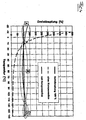
- Fig. 4 the qualitative course of the rotary damping is to be taken as the temperature.
- the dashed line shows approximately hyperbolic progression for the uncompensated case.
- the solid line shows the course with compensation, which can be divided into three temperature ranges A, B and C.
- the area B is determined primarily by the approximately linearly decreasing temperature of the connection channel (13) (variable throttle). At approx. 20 ° C and at approx. 95 ° C, it is possible to ideally compensate for the influence of the changing viscosity. In the temperature range in between there is a good approximation to the ideal course.
- region A the overpressure valves (18) and bypasses not described in detail in section C determine the course of the rotational damping above the temperature.
Description
Die Erfindung betrifft eine drehelastische Kupplungseinrichtung mit mindestens zwei miteinander verbundene Biegedrehfedern, wobei mindestens eine schraubenförmigen Biegedrehfeder konzentrisch um eine Drehachse angeordnet ist, wobei eine Antriebswelle und eine Abtriebswelle jeweils mit der Biegedrehfeder in Wirkverbindung bringbar und entgegen einem rückstellenden Drehmoment der Biegedrehfeder relativ zueinander um die Drehachse verdrehbar sind und mit einer Dämpfungseinrichtung.The invention relates to a torsionally flexible coupling device with at least two mutually connected bending torsion springs, wherein at least one helical bending torsion spring is arranged concentrically about an axis of rotation, wherein a drive shaft and an output shaft respectively engageable with the bending torsion spring and against a restoring torque of the bending torsion spring relative to each other about the axis of rotation are rotatable and with a damping device.
Derartige drehelastische Kupplungseinrichtungen sind aus der Praxis bekannt und werden beispielsweise bei Fährzeugen mit einem Verbrennungsmotor dazu verwendet, um die ungleichförmigen Drehbewegungen einer Kurbelwelle des Verbrennungsmotors und den dadurch verursachten Vibrationen und Geräuschen entgegenzuwirken. Die unerwünschten Vibrationen, insbesondere die hohen Amplituden der Drehschwingungen und die dadurch bewirkte höhere mechanische Belastung der angeschlossenen Bauteile sowie die oftmals als störend empfundene Geräuschentwicklung nehmen mit höherer Leistung und insbesondere mit zunehmendem Drehmoment des Verbrennungsmotors deutlich zu.Such torsionally flexible coupling devices are known in practice and are used for example in vehicles with an internal combustion engine to counteract the non-uniform rotational movements of a crankshaft of the internal combustion engine and the vibrations and noise caused thereby. The unwanted vibrations, in particular the high amplitudes of the torsional vibrations and the resulting higher mechanical load on the connected components and the often perceived as disturbing noise increase significantly with higher power and in particular with increasing torque of the internal combustion engine.
Zu beobachten ist, dass in der Entwicklung befindliche Motoren immer höhere mittlere Drehmomente bereitstellen und dass künftig mit deutlich verstärkter dynamische Anregung zu rechnen ist. Die derzeit im Antriebstrang eingesetzten Drehfedern stoßen im vorgegebenen Bauraum bei noch weiter steigenden mittleren Drehmomenten und steigender dynamischer Anregung an Grenzen, d.h. sie können den Erfordernissen entsprechend nicht noch drehweicher ausgebildet werden.It can be observed that engines under development provide ever higher average torques and that in the future significantly increased dynamic excitation can be expected. Currently used in the powertrain Torsion springs encounter in the given space at even higher average torques and increasing dynamic excitation limits, ie they can not be designed to meet the requirements even more torsionally.
Es besteht also der Bedarf, Drehfedern hoher Leistungsdichte zu entwickeln. Unter hoher Leistungsdichte soll hier das auf den Bauraum bezogen übertragbare hohe Drehmoment bei vorgegebener Drehfederrate oder bei vorgegebenem Drehmoment die niedrige Drehfederrate zu verstehen sein. Bei gegebenen Drehträgheiten der Antriebstrangkomponenten würde eine kleinere Drehfederrate eine verbesserte Isolation bedeuten, d.h. die Drehungleichförmigkeit des Verbrennungsmotors hätte weniger Einfluss auf den Triebstrang. Zudem würde die drehweichere Anbindung des Triebstrangs an den Verbrennungsmotor kleinere Betriebsdrehzahlen ermöglichen, die wiederum ein verbrauchsgünstigeres Fahren ermöglichen könnten.There is therefore a need to develop torsion springs of high power density. Under high power density is here to be understood in terms of space transferable high torque at a given torsion spring rate or for a given torque, the low torsion spring rate to understand. For given rotational inertias of the powertrain components, a smaller torsion spring rate would provide improved isolation, i. the rotational nonuniformity of the internal combustion engine would have less influence on the drive train. In addition, the drier connection of the drive train to the internal combustion engine would allow smaller operating speeds, which in turn could enable more fuel-efficient driving.
Einfache drehelastische Kupplungseinrichtungen, wie sie aus dem Stand der Technik bekannt sind oder beispielsweise aus einem geeigneten Elastomer hergestellte Torsions- oder Drehfedern, weisen oftmals keine ausreichend hohe Leistungsdichte auf. Dabei wird von einer hohen Leistungsdichte einer Drehfeder ausgegangen, wenn bauraumbezogen bei einer vorgegebenen Federrate ein hohes Drehmoment übertragen werden kann oder wenn bei einem vorgegebenen hohen Drehmoment eine niedrige Federrate erreicht wird.Simple torsionally flexible coupling devices, as known from the prior art or, for example, torsion or torsion springs made of a suitable elastomer, often do not have a sufficiently high power density. It is assumed that a high power density of a torsion spring when space-related at a given spring rate, a high torque can be transmitted or when a low spring rate is achieved at a predetermined high torque.
Es sind beispielsweise aus
Aus
Drehelastische Kupplungseinrichtungen der eingangs genannten Gattung sind beispielsweise aus
Es hat sich allerdings gezeigt, dass mit immer leistungsstärkeren Motoren verstärkt auftretende Schwingungen in dem Antriebsstrang auftreten und die dadurch bewirkte mechanische Belastung und Geräuschentwicklung immer leistungsfähigere drehelastische Kupplungseinrichtungen erfordert. In den meisten Fällen nimmt der für die drehelastische Kupplungseinrichtung zur Verfügung stehende Raum jedoch nicht in dem Maße zu, wie es für die Wirkungshöhe, bzw. Leistungsdichte der drehelastischen Kupplungseinrichtung gemäß der eingangs genannten Gattung erforderlich wäre.However, it has been found that occur with increasingly powerful engines increasingly occurring vibrations in the drive train and the mechanical stress and noise caused by this ever more powerful torsionally flexible coupling devices required. In most cases, however, the space available for the torsionally flexible coupling device does not increase to the extent that would be required for the effective height or power density of the torsionally flexible coupling device according to the aforementioned type.
Für eine der Drehfeder parallel geschaltete Drehdämpfung gibt es gegenläufige Anforderungen. So steht eine kleine Dämpfung für gute Isolation, während eine hohe Dämpfung für kleine Amplituden beim Resonanzdurchlauf sowie beim Motorstart und Motorstopp vorteilhaft wäre. Die nach dem Stand der Technik übliche, aus Komfortgründen klein gewählte Drehdämpfung führt deshalb oft zu unerwünschten hohen Amplituden oder sogar zu sogenannten Resonanzhängern, d.h. der Resonanzdurchlauf gelingt nicht.For one of the torsion spring parallel rotary damping there are opposite requirements. Thus, a small attenuation stands for good insulation, while a high attenuation for small amplitudes in the resonant passage as well as the engine start and engine stop would be beneficial. The usual in the art, for reasons of comfort small selected rotational loss therefore often leads to undesirable high amplitudes or even to so-called resonance hangers, i. the resonance run does not succeed.
Das Dämpfungsvermögen einer mit einem Dämpfungsfluid betriebenen Dämpfungseinrichtung wird dabei maßgeblich von dem verwendeten Dämpfungsfluid und dem Strömungswiderstand der Dämpfungseinrichtung abhängen. Die aus der Praxis bekannten Dämpfungseinrichtungen sind hinsichtlich des vorgegebenen Dämpfungsvermögens darauf ausgelegt, die Schwingungen des Antriebsstrangs eines Kraftfahrzeugs mit einem Verbrennungsmotor während dessen Betrieb gut zu isolieren. Die bei einem Startvorgang oder Abstellvorgang des Verbrennungsmotors auftretenden resonanten Schwingungen können oftmals nur unzureichend gedämpft werden.The damping capacity of a damping device operated with a damping fluid will depend decisively on the damping fluid used and the flow resistance of the damping device. The known from practice damping devices are designed with respect to the predetermined damping capacity to isolate the vibrations of the drive train of a motor vehicle with an internal combustion engine during its operation well. The occurring during a startup or shutdown of the engine resonant vibrations can often be insufficiently damped.
Weiterhin hat sich gezeigt, dass die aus der Praxis bekannten Fluid verdrängenden Dämpfungseinrichtungen üblicherweise mit einem Dämpfungsfluid betrieben werden, dessen Viskosität stark temperaturabhängig ist. In Abhängigkeit von der sich temperaturbedingt ändernden Viskosität ändert sich in entsprechender Weise auch die Dämpfungswirkung der Fluid verdrängenden Dämpfungseinrichtung. Dies führt dazu, dass die Wirkung der Dämpfungseinrichtung teilweise sehr stark von der jeweils aktuellen Betriebstemperatur der drehelastischen Kupplungseinrichtung und insbesondere des darin befindlichen Dämpfungsfluids abhängt. Eine derartige Abhängigkeit der Dämpfungswirkung von der Betriebstemperatur ist nicht gewünscht.Furthermore, it has been shown that the known from practice fluid displacing damping devices are usually operated with a damping fluid whose viscosity is highly temperature-dependent. Depending on the temperature-changing viscosity changes in a corresponding manner, the damping effect of the fluid displacing damping device. As a result, the effect of the damping device sometimes depends very greatly on the respective current operating temperature of the torsionally elastic coupling device and in particular of the damping fluid therein. Such a dependence of the damping effect on the operating temperature is not desired.
Aufgabe der vorliegenden Erfindung ist es demzufolge, eine drehelastische Kupplungseinrichtung der eingangs genannten Gattung konstruktiv einfach und kostengünstig so auszugestalten, dass eine möglichst große Dämpfungswirkung und eine dadurch erreichbare Verringerung der mechanischen Schwingungsbelastung und Geräuschentwicklung des Antriebsstrangs auch bei einem Motorstart und Motorstopp bzw. den hierbei erforderlichen Resonanzdurchläufen erzwungener Schwingungen ermöglicht wird.Object of the present invention is therefore to provide a torsionally flexible coupling device of the type mentioned structurally simple and inexpensive in such a way that the greatest possible damping effect and achievable thereby reducing the mechanical vibration load and noise of the drive train even at an engine start and engine stop or the case required Resonance cycles of forced vibrations is made possible.
Die Aufgabe wird erfindungsgemäß dadurch gelöst, dass die Dämpfungseinrichtung (8) mindestens zwei über eine Drosseleinrichtung (10) miteinander in Verbindung stehende, mit einem Dämpfungsfluid befüllbare Fluidkammern (9) aufweist und dass die Drosseleinrichtung (10) mindestens einen die mindestens zwei Fluidkammern (9) verbindenden Verbindungskanal (13) aufweist, dessen fluiddurchströmbare Querschnittsfläche veränderbar ist.The object is achieved according to the invention in that the damping device (8) has at least two fluid chambers (9) which can be filled with a damping fluid via a throttle device (10) and in that the throttle device (10) comprises at least one of the at least two fluid chambers (9 ) connecting the connecting channel (13), the fluiddurchströmbare cross-sectional area is variable.
Durch die Verwendung von zwei oder mehreren Biegedrehfedern kann bei einem vorgegebenen und oftmals möglichst gering zu haltenden Bauraum eine größere Leistungsdichte des Biegedrehfedersatzes erreicht werden, als es mit einer einzelnen Biegedrehfeder möglich wäre. Dies bedeutet, dass bei gleichem Bauraum und gleich bleibender Federrate ein hohes Drehmoment übertragen werden kann oder bei einem gleich bleibend hohen Drehmoment eine niedrigere Federrate erzielt werden kann. Die aus der Praxis bekannten Biegedrehfedern können dabei weitgehend unverändert verwendet werden, so dass keine aufwändige Modifikation erforderlich wäre. Die jeweiligen Abmessungen der einzelnen miteinander verbundenen Biegedrehfedern können dabei zweckmäßigerweise so aufeinander abgestimmt sein, dass die Biegedrehfedern beispielsweise konzentrisch und im Wesentlichen in einer Ebene senkrecht zur Drehachse angeordnet sein können, so dass insbesondere in axialer Richtung lediglich ein geringer Bauraum zur Verfügung stehen muss und die miteinander kombinierten Biegedrehfedern das vorgegebene Volumen bei möglichst geringen Außenabmessungen bestmöglich ausnutzen.By using two or more bending torsion springs, a greater power density of the bending torsion spring set can be achieved with a predetermined and often as small as possible installation space than would be possible with a single bending torsion spring. This means that with the same space and constant spring rate, a high torque can be transmitted or at a consistently high torque, a lower spring rate can be achieved. The known from practice bending torsion springs can be used largely unchanged, so that no complex modification would be required. The respective dimensions of the individual interconnected bending torsion springs can be suitably coordinated so that the bending torsion springs can be arranged, for example concentric and substantially in a plane perpendicular to the axis of rotation, so that in particular only a small space must be available in the axial direction and the Bending torsion springs combined with each other make the best possible use of given volumes with the smallest possible external dimensions.
Es ist vorgesehen, dass die Dämpfungseinrichtung mindestens zwei über eine Drosseleinrichtung miteinander in Verbindung stehende, mit einem Dämpfungsfluid befüllbare Fluidkammern aufweist. Zweckmäßigerweise ist vorgesehen, dass das verwendete Dämpfungsfluid gleichzeitig als Schmiermittel für die Biegedrehfedern verwendet wird und dass in den Fluidkammern befindliche Dämpfungsfluid auch die Biegedrehfedern umströmen kann.It is provided that the damping device has at least two fluid chambers which are connected to one another via a throttle device and can be filled with a damping fluid. Appropriately, it is provided that the damping fluid used is used simultaneously as a lubricant for the bending torsion springs and that located in the fluid chambers damping fluid can flow around the bending torsion springs.
Um auch während des Start- und Abstellvorgangs und den dabei auftretenden Drehzahlen eine möglichst gute Dämpfungswirkung zu ermöglichen ist vorgesehen, dass die Drosseleinrichtung mindestens einen die mindestens zwei Fluidkammern verbindenden Verbindungskanal aufweist, dessen fluiddurchströmbare Querschnittsfläche veränderbar ist. Während des Start- und Abstellvorgangs des Verbrennungsmotors kann die fluiddurchströmbare Querschnittsfläche des Verbindungskanals verkleinert und der Strömungswiderstand dadurch erhöht werden, so dass eine asymptotische oder überkritische Dämpfung beim Start- und Abstellvorgang erreicht werden kann. Während des normalen Betriebs des Verbrennungsmotors kann die fluiddurchströmbare Querschnittsfläche vergrößert werden, so dass der Strömungswiderstand und damit die Dämpfungswirkung der Drosseleinrichtung an den normalen Betrieb angepasst und eine optimale Bedämpfung der während des normalen Betriebs auftretenden Schwingungen ermöglicht wird.In order to enable the best possible damping effect also during the start and stop operation and the rotational speeds occurring, it is provided that the throttle device has at least one connecting channel connecting the at least two fluid chambers, the fluid-flowable cross-sectional area of which can be changed. During the start-up and shut-down of the internal combustion engine, the fluid-flow cross-sectional area of the connecting channel can be reduced and the flow resistance can be increased thereby, so that asymptotic or supercritical damping can be achieved during the starting and stopping process. During normal operation of the internal combustion engine, the fluid-flow cross-sectional area can be increased, so that the flow resistance and thus the damping effect of the throttle device adapted to the normal operation and an optimal damping of the vibrations occurring during normal operation is enabled.
Mit einfachen Mitteln kann eine geeignete Veränderung der Querschnittsfläche des Verbindungskanals dadurch erreicht werden, dass in dem Verbindungskanal ein radial zwischen einer den Verbindungskanal verschließenden Verschlussstellung und einer den Verbindungskanal öffnenden Durchlassstellung verlagerbares Verschlusselement aufweist. Die von dem Verschlusselement in seiner Durchlassstellung vorgegebene, beziehungsweise freigegebene Querschnittsfläche des Verbindungskanals ist dabei zweckmäßigerweise so bemessen, dass der Strömungswiderstand der Drosseleinrichtung in Abhängigkeit von dem verwendeten Dämpfungsfluid eine an den normalen Betrieb des Verbrennungsmotors angepasste Dämpfungswirkung ergibt. In seiner Verschlussstellung bewirkt das in dem Verbindungskanal angeordnete Verschlusselement eine deutlich höhere, beziehungsweise asymptotische oder überkritische Bedämpfung der drehelastischen Kupplungseinrichtung, so dass nahezu keine resonanten Schwingungen auftreten.With simple means, a suitable change in the cross-sectional area of the connecting channel can be achieved in that in the connecting channel has a radially displaceable between a closure channel closing the closing position and a passage opening opening the connecting channel. The one of the Closing element in its passage position predetermined, or released cross-sectional area of the connecting channel is expediently dimensioned so that the flow resistance of the throttle device depending on the damping fluid used results in a matched to the normal operation of the internal combustion engine damping effect. In its closed position, the closure element arranged in the connecting channel causes a significantly higher, or asymptotic, or supercritical damping of the torsionally elastic coupling device, so that virtually no resonant oscillations occur.
Gemäß einer vorteilhaften Ausgestaltung des Erfindungsgedankens ist vorgesehen, dass das Verschlusselement entgegen der Rückstellkraft einer Federeinrichtung verlagerbar ist. Ganz besonders vorteilhaft ist es dabei, wenn die Rückstellkraft der Federeinrichtung radial gerichtet und in Abhängigkeit von der Masse des Verschlusselements so vorgegeben ist, dass sich das Verschlusselement bei einer vorgebbaren Umdrehungszahl der drehelastischen Kupplungseinrichtung von der Verschlussstellung in die Durchlassstellung verlagert. Auf diese Weise kann mit einfachen konstruktiven Mitteln eine drehzahlabhängige Veränderung der Dämpfungswirkung der Dämpfungseinrichtung herbeigeführt werden. Eine gesonderte Steuereinrichtung, welche in Abhängigkeit von der beispielsweise mittels Sensoren zu ermittelnden Drehzahl den Strömungswiderstand und damit die Dämpfungswirkung der Drosseleinrichtung verändert, ist demzufolge nicht notwendig.According to an advantageous embodiment of the inventive concept it is provided that the closure element against the restoring force of a spring device is displaced. It is particularly advantageous if the restoring force of the spring device is radially directed and predetermined depending on the mass of the closure element such that the closure element is displaced from the closed position into the open position at a prescribable number of revolutions of the torsionally flexible coupling device. In this way, a speed-dependent change in the damping effect of the damping device can be brought about with simple structural means. A separate control device, which changes the flow resistance and thus the damping effect of the throttle device as a function of the speed to be determined, for example, by means of sensors, is therefore not necessary.
Die maximale Verlagerung des Verschlusselements in radialer Richtung wird dadurch begrenzt, dass die Federeinrichtung das Verschlusselement in radialer Richtung gegen eine Anschlagfläche abstützt.The maximum displacement of the closure element in the radial direction is limited by the fact that the spring device supports the closure element in the radial direction against a stop surface.
Sollte es in Einzelfällen erforderlich werden oder vorteilhaft sein, so kann vorgesehen sein, dass das fluiddurchströmbare Aussparungen und/oder Bypasskanäle im Bereich um das verlagerbare Verschlusselement angeordnet sind.Should it be necessary or advantageous in individual cases, provision may be made for the recesses and / or bypass channels through which fluid can flow to be arranged in the region around the displaceable closure element.
Zusätzlich oder ergänzend hierzu kann vorgesehen sein, dass die Drosseleinrichtung mindestens ein Überdruckventil aufweist. Zweckmäßigerweise weist dabei das mindestens eine Überdruckventil einen entgegen einer Rückstellkraft einer Überdruckventil-Federeinrichtung verlagerbaren Ventilkörper auf. Insbesondere während der asymptotischen oder überkritischen Bedämpfung bei dem Start- und Abstellvorgang des angeschlossenen Verbrennungsmotors können kurzzeitig sehr große Druckkräfte auf das Dämpfungsfluid einwirken. Um eine übermäßige mechanische Beanspruchung der die Fluidkammern begrenzenden Bauteile und der Drosseleinrichtung insbesondere bei tiefen Temperaturen zu vermeiden, wird durch das Überdruckventil eine Umlagerung des Dämpfungsfluids zwischen den mindestens zwei Fluidkammern ermöglicht und die Dämpfungswirkung auf zulässige Werte begrenzt.Additionally or additionally, it can be provided that the throttle device has at least one pressure relief valve. Expediently, the at least one overpressure valve has a valve body which can be displaced counter to a restoring force of a pressure relief valve spring device. In particular during the asymptotic or supercritical damping during the starting and stopping process of the connected internal combustion engine, very large pressure forces can briefly act on the damping fluid. In order to avoid excessive mechanical stress on the fluid chambers limiting components and the throttle device, especially at low temperatures, a rearrangement of the damping fluid between the at least two fluid chambers is made possible by the pressure relief valve and limits the damping effect to allowable values.
Vorzugsweise ist vorgesehen, dass die mindestens zwei Biegedrehfedern parallel wirkend miteinander verbunden sind. Je nach den vorgegebenen Anforderungen an die drehelastische Kupplungseinrichtung können auch eine Reihenschaltung oder im Falle von mehreren Biegedrehfedern eine gemischte Anordnung der einzelnen Biegedrehfedern zweckmäßig und vorteilhaft sein.It is preferably provided that the at least two bending torsion springs are connected to each other in parallel. Depending on the specified requirements for the torsionally flexible coupling device, a series connection or, in the case of a plurality of bending torsion springs, a mixed arrangement of the individual bending torsion springs can be expedient and advantageous.
Zur Vermeidung einer unerwünschten Unwucht während des Betriebs ist vorgesehen, dass jeder Biegedrehfeder Führungsmittel zugeordnet sind, welche bei einem Aufweiten oder Kontrahieren der zugeordneten Biegedrehfeder eine konzentrische Anordnung dieser Biegedrehfeder vorgeben. Die Führungsmittel können Führungshülsen aufweisen, auf oder in denen Führungsstege gleiten.To avoid unwanted imbalance during operation, it is provided that each bending torsion spring are associated with guide means, which specify a concentric arrangement of this bending torsion spring when expanding or contracting the associated bending torsion spring. The guide means may comprise guide sleeves on or in which guide webs slide.
Es ist auch denkbar, den Biegedrehfedern Koppelringe mit Nocken und Führungsstegen zuzuordnen. Als besonders vorteilhaft hat sich die Anformung der Führungsstege an die Nocken herausgestellt, wobei die Nocken gleichzeitig die Führungsstege bilden. Sofern es zweckmäßig erscheint, können auch Kompensationsmassen vorgesehen sein, die derart angeordnet sind, dass sie sich im Falle der nicht belasteten Biegedrehfeder bezogen auf die Drehachse gegenüber liegen und im Falle einer Relativverdrehung der jeweiligen Enden der Biegedrehfeder eine dadurch bewirkte Unwucht kompensieren bzw. weitgehend unterdrücken.It is also conceivable to associate the bending torsion coupling rings with cams and guide webs. To be particularly advantageous, the Anformung the guide webs has been found to the cams, wherein the cams form the guide webs at the same time. Insofar as it appears expedient, compensation masses can also be provided which are arranged in such a way that, in the case of the unstressed bending torsion spring, they lie opposite to the axis of rotation and, in the case of a relative rotation of the respective ends of the bending torsion spring, compensate or substantially suppress an imbalance caused thereby ,
Einer besonders vorteilhaften Ausgestaltung des Erfindungsgedankens zufolge ist vorgesehen, dass die Dämpfungseinrichtung radial im Abstand zu den mindestens zwei Biegedrehfedern angeordnet ist. Die Dämpfungseinrichtung kann dabei relativ zur Drehachse innen angeordnet und von den Biegedrehfedern umgeben sein oder aber die Biegedrehfedern außen umgeben. Auf diese Weise kann eine drehelastische Kupplungseinrichtung mit einer großen Leistungsdichte der Biegedrehfedern und mit einer erforderlichen Drehdämpfungshöhe bei geringer axialer Erstreckung ausgestaltet sein. Eine geringe axiale Ausdehnung in der Kupplungseinrichtung ist insbesondere bei einer drehelastischen Dämpfung des Antriebsstrangs von Kraftfahrzeugen ein wesentlicher Vorteil.A particularly advantageous embodiment of the inventive concept according to it is provided that the damping device is arranged radially at a distance from the at least two bending torsion springs. The damping device can be arranged inside relative to the axis of rotation and be surrounded by the bending torsion springs or outside the bending torsion springs surrounded. In this way, a torsionally flexible coupling device can be designed with a large power density of the bending torsion springs and with a required rotational damping height at low axial extent. A small axial extent in the coupling device is a significant advantage, in particular in the case of a torsionally elastic damping of the drive train of motor vehicles.
Das Dämpfungsvermögen der Dämpfungseinrichtung kann in vorteilhafter Weise dadurch beeinflusst werden, dass die Fluidkammern nur teilweise mit einem flüssigen Dämpfungsfluid befüllt sind. Während des Betriebs wird sich das flüssige Dämpfungsfluid auf Grund der Drehbewegung der drehelastischen Kupplungseinrichtung in den radial außen liegenden Bereichen der Fluidkammern ansammeln. In den radial innen liegenden Bereichen verbleibt ein Luftpolster. Bei einer drehelastischen Beanspruchung der Kupplungseinrichtung bilden sich diese Luftpolster insbesondere um die das flüssige Dämpfungsfluid verdrängenden Bauteile wie beispielsweise in die Fluidkammern ragende Stege oder die Drosseleinrichtung aus und bewirken eine kleine Dämpfung bei kleinen Amplituden. Bei großen Amplituden wird nach dem Umverlagern der Luft und/oder einer Verdichtung der Luftpolster die erforderliche hohe Dämpfung bereitgestellt. Gleichzeitig wird durch die teilweise Befüllung der Fluidkammern mit einem flüssigen Dämpfungsfluid auch der temperaturabhängigen Wärmeausdehnung der geeigneten flüssigen Dämpfungsfluide Rechnung getragen. Die während des Betriebs mit steigender Temperatur auftretende Wärmeausdehnung eines geeigneten flüssigen Dämpfungsfluids kann bei einer teilweisen Befüllung der Fluidkammern mit diesem Dämpfungsfluid durch das verbleibende Luftpolster ausgeglichen werden, ohne dass bei einer Anordnung, die zur Umgebung hin dicht ist, ein übermäßiger Druckanstieg erfolgt, der eine unerwünscht hohe mechanische Belastung der drehelastischen Kupplungseinrichtung zur Folge hätte.The damping capacity of the damping device can be influenced in an advantageous manner in that the fluid chambers are only partially filled with a liquid damping fluid. During operation, due to the rotational movement of the torsionally flexible coupling device, the liquid damping fluid will accumulate in the radially outer regions of the fluid chambers. In the radially inner regions remains an air cushion. In a torsionally elastic stress on the coupling device, these air cushions form in particular around the liquid damping fluid displacing components such as projecting into the fluid chambers webs or the throttle device and cause a small attenuation at low amplitudes. For large amplitudes, the required high attenuation is provided after relocating the air and / or a compression of the air cushion. At the same time, the partial filling of the fluid chambers with a liquid damping fluid also takes into account the temperature-dependent thermal expansion of the suitable liquid damping fluids. The occurring during operation with increasing temperature thermal expansion of a suitable liquid damping fluid can be compensated for at a partial filling of the fluid chambers with this damping fluid through the remaining air cushion, without that in an arrangement that is dense to the environment, a Excessive pressure increase takes place, which would result in an undesirably high mechanical load on the torsionally flexible coupling device.
Es hat sich gezeigt, dass die hinsichtlich vieler Anforderungen für eine Verwendung als flüssiges Dämpfungsfluid geeigneten Polyglykolöle eine stark temperaturabhängige Viskosität aufweisen und sich das Dämpfungsvermögen der Dämpfungseinrichtung bei Verwendung von beispielsweise Polyglykolölen mit zunehmender oder abnehmender Temperatur stark verändert. Das Dämpfungsvermögen der Dämpfungseinrichtung kann demzufolge bei den bereits bekannten drehelastischen Kupplungseinrichtungen nur innerhalb eines engen Temperaturbereichs so vorgegeben werden, dass eine geeignete Bedämpfung der üblicherweise auftretenden Schwingungen und mechanischen Erschütterungen während des Betriebs möglich ist. Verändert sich die Temperatur, so ändem sich die Viskosität des verwendeten Dämpfungsfluids und damit auch das Dämpfungsvermögen der drehelastischen Kupplungseinrichtung in einem oftmals unerwünscht großen Ausmaß.It has been found that the polyglycol oils which are suitable with regard to many requirements for use as liquid damping fluid have a strongly temperature-dependent viscosity and the damping capacity of the damping device greatly changes with increasing or decreasing temperature when using, for example, polyglycol oils. The damping capacity of the damping device can therefore be specified in the already known torsionally flexible coupling devices only within a narrow temperature range so that a suitable damping of the usually occurring vibrations and mechanical shocks during operation is possible. If the temperature changes, the viscosity of the damping fluid used and thus also the damping capacity of the torsionally flexible coupling device changes to an often undesirably large extent.
Um eine temperaturbedingt hervorgerufene Veränderung des Dämpfungsvermögens in einem vorgegebenen kleinen Bauraum möglichst gut kompensieren zu können ist es gemäß einer vorteilhaften Ausgestaltung des Erfindungsgedankens vorgesehen, dass die Drosseleinrichtung in dem Verbindungskanal ein in seiner Formgebung veränderbares Drosselelement aufweist. Die Formgebung des veränderbaren Drosselelements kann dabei zweckmäßigerweise derart verändert werden, dass der durch das Drosselelement bewirkte Strömungswiderstand für das Dämpfungsfluid eine temperaturbedingt sich ändernde Viskosität des Dämpfungsfluids möglichst kompensiert.In order to compensate for a temperature-induced change in the damping capacity in a given small space as well as possible it is provided according to an advantageous embodiment of the inventive concept that the throttle device in the connecting channel has a variable in its shape throttle element. The shape of the variable throttle element can be suitably changed such that the caused by the throttle element flow resistance for the damping fluid as possible compensated for a temperature-changing viscosity of the damping fluid.
Es kann auch vorgesehen sein, dass das Drosselelement verlagerbar ist und eine Außenwand des Drosselelements zumindest abschnittsweise eine die fluiddurchströmbare Querschnittsfläche des Verbindungskanals begrenzende Seitenwand des Verbindungskanals bildet. Wird die Außenwand des Drosselelements in den Verbindungskanal hinein verlagert, so wird dadurch die Querschnittsfläche des Verbindungskanals verringert. Wird dagegen die Außenwand des Drosselelements aus dem Verbindungskanal heraus verlagert, so vergrößert sich die Querschnittsfläche des Verbindungskanals entsprechend.It can also be provided that the throttle element is displaceable and an outer wall of the throttle element, at least in sections, defining a fluid-flowable cross-sectional area of the connecting channel Side wall of the connecting channel forms. If the outer wall of the throttle element is displaced into the connecting channel, this reduces the cross-sectional area of the connecting channel. If, on the other hand, the outer wall of the throttle element is displaced out of the connecting channel, the cross-sectional area of the connecting channel increases correspondingly.
Eine geeignete Verlagerung eines relevanten Bereichs der Außenwand kann in einfacher Weise dadurch bewirkt werden, dass in einem Innenraum des Drosselelements mindestens ein Dehnkörper angeordnet Ist. Eine Ausdehnung des Dehnkörpers kann bei einer geeigneten Festlegung des Dehnkörpers unmittelbar eine entsprechende Verlagerung der Außenwand und eine damit einhergehend veränderteQuerschnittsfläche des Verbindungskanals bewirken.A suitable displacement of a relevant region of the outer wall can be effected in a simple manner by arranging at least one expansion element in an inner space of the throttle element. An expansion of the expansion body can cause a corresponding displacement of the outer wall and a concomitantly changed cross-sectional area of the connecting channel with a suitable determination of the expansion body directly.
Um In einfacher Welse eine temperaturabhängige Veränderung der fluiddurchströmbaren Querschnittsfläche des Verbindungskanals und damit dessen Strömungswiderstands herbeiführen zu können ist vorgesehen, dass der Dehnkörper sich bei steigender Temperatur ausdehnt und durch eine dadurch bedingte Verformung der Außenwand die fluiddurchströmbare Querschnittsfläche des Verbindungskanals verringert.In order to be able to induce a temperature-dependent change in the fluid-flowable cross-sectional area of the connection channel and thus its flow resistance in simple catfish, it is provided that the expansion element expands with increasing temperature and reduces the fluid-throughflowable cross-sectional area of the connection channel due to consequent deformation of the outer wall.
Gemäß einer besonders vorteilhaften Ausgestaltung des Erfindungsgedankens ist vorgesehen, dass die temperaturbedingte Ausdehnung des Dehnkörpers an die temperaturbedingte Änderung der Viskosität des Dämpfungsfluids in geeigneter Weise angepasst ist, so dass in dem Maß, wie sich das Dämpfungsvermögen der Dämpfungseinrichtung auf Grund der temperaturbedingten Viskositätsänderung des Dämpfungsfluids ändern würde, eine diese Änderung weitgehend kompensierende Veränderung der Querschnittsfläche des Verbindungskanals durch die ebenfalls temperaturbedingte Ausdehnung des Dehnkörpers herbeigeführt wird.According to a particularly advantageous embodiment of the inventive concept it is provided that the temperature-induced expansion of the expansion body is adapted to the temperature-induced change in the viscosity of the damping fluid in a suitable manner, so that to the extent that change the damping capacity of the damping device due to the temperature-induced change in viscosity of the damping fluid would, a change largely compensating this change in the cross-sectional area of the connecting channel is brought about by the likewise temperature-induced expansion of the expansion body.
Durch eine geeignete Anpassung und Abstimmung der temperaturbedingten Ausdehnung des Dehnkörpers an das verwendete Dämpfungsfluid und insbesondere dessen temperaturbedingte Viskositätsänderung kann dabei mit einfachen Mitteln eine über einen großen Temperaturbereich näherungsweise gleich bleibende Dämpfungswirkung der Dämpfungseinrichtung gewährleistet werden.By suitable adaptation and coordination of the temperature-induced expansion of the expansion body to the damping fluid used and in particular its temperature-induced viscosity change can be ensured with simple means over a wide temperature range approximately constant damping effect of the damping device.
Da das in seinen Abmessungen veränderbare Drosselelement in der Dämpfungseinrichtung angeordnet ist und keinen zusätzlichen Bauraum beansprucht, können die Dämpfungseigenschaften der drehelastischen Kupplungseinrichtung bei einem möglichst geringen Bauraum in vorteilhafter Weise verbessert werden.Since the variable in its dimensions throttle element is arranged in the damping device and does not claim any additional space, the damping properties of the torsionally flexible coupling device can be improved with the smallest possible space in an advantageous manner.
Es ist ohne Weiteres möglich, dass das die temperaturbedingte Viskositätsänderung des Dämpfungsfluid kompensierende Drosselelement und das drehzahlabhängig die Dämpfungswirkung verändernde Verschlusselement miteinander kombiniert und in einem Bauteil verwirklicht werden können.It is readily possible that the temperature-induced change in viscosity of the damping fluid-compensating throttle element and the speed-dependent the damping effect changing closure element combined with each other and can be realized in one component.
Es ist natürlich ebenso denkbar, dass ein in seinen Abmessungen veränderbares Drosselelement unabhängig von einem verlagerbaren Verschlusselement in einer drehelastischen Kupplungseinrichtung angeordnet ist.It is of course also conceivable that a throttle element variable in its dimensions is arranged independently of a displaceable closure element in a torsionally flexible coupling device.
Eine erfindungsgemäße Kompensation der sich temperaturbedingt ändernden Viskosität des verwendeten Dämpfungsfluids durch Verwendung eines in seinen Abmessungen veränderbaren Drosselelements kann natürlich auch erfindungsgemäß mit anderen drehelastischen Kupplungseinrichtungen kombiniert werden, die beispielsweise lediglich eine schraubenförmige Biegedrehfeder aufweisen. In gleicher Weise kann auch ein gegebenenfalls drehzahlabhängig radial verlagerbares Verschlusselement mit drehelastischen Kupplungseinrichtungen mit beispielsweise nur einer Biegedrehfeder kombiniert werden, um bei geringen Drehzahlen eine asymptotische oder überkritische Bedämpfung der in diesen Drehzahlbereichen üblicherweise auftretenden resonanten Schwingungen zu ermöglichen.A compensation according to the invention of the temperature-dependent changing viscosity of the damping fluid used by using a variable in size throttle element can of course also be combined according to the invention with other torsionally flexible coupling devices, for example, have only a helical bending torsion spring. In the same way, an optionally speed-dependent radially displaceable closure element can be combined with torsionally elastic coupling devices with, for example, only one bending torsion spring In order to allow at low speeds an asymptotic or supercritical damping of the resonant vibrations usually occurring in these speed ranges.
Es ist ebenso denkbar, dass die vorgenannte Kompensation der sich temperaturbedingt ändernden Viskosität mit einer formschlüssigen oder reibschlüssigen Verbindung zwischen An- und Abtriebswelle kombiniert wird, welche die Relativbewegung zwischen An- und Abtriebswelle während des Motor-Starts/Stopps verhindert oder deutlich reduziert.It is also conceivable that the aforementioned compensation of the temperature-changing viscosity is combined with a positive or frictional connection between input and output shaft, which prevents or significantly reduces the relative movement between the input and output shaft during engine start / stop.
Nachfolgend wird ein Ausführungsbeispiel des Erfindungsgedankens näher erläutert, das in der Zeichnung dargestellt ist. Es zeigt:
-
Figur 1 -
Figur 2 eine halbseitige Schnittansicht längs der Drehachse der inFigur 1 -
Figur 3den Figuren 1 und2 dargestellten drehelastischen Kupplungseinrichtung enthalten ist und -
Figur 4
-
FIG. 1 3 is a sectional view perpendicular to the axis of rotation of a torsionally flexible coupling device with two concentrically arranged bending torsion springs and an internally arranged damping device, -
FIG. 2 a half-sectional view along the axis of rotation of inFIG. 1 shown torsionally flexible coupling device, -
FIG. 3 an enlarged sectional view of a radially displaceable closure element, which in the damping device in theFIGS. 1 and2 shown torsionally elastic coupling device is included and -
FIG. 4 a qualitative representation of the calculated by means of simulations damping effect of the damping device, or without a compensation according to the invention of the temperature-dependent change in viscosity of a damping fluid used.
Eine in den
Zwischen der innenliegenden Biegedrehfeder 3 und der Drehdämpfemabe 11a ist eine Dämpfungseinrichtung 8 angeordnet. Die Dämpfungseinrichtung 8 weist vier Fluidkammern 9 auf, von denen jeweils zwei Fluidkammern 9 über eine Drosseleinrichtung 10 miteinander in Verbindung stehen. Die Fluidkammern 9 werden nach innen durch eine innere Hülse 11a und eine äußere Hülse 11b begrenzt. Die innere Hülse 11 a und die äußere Hülse 11 b sind starr mit den der Abtriebswelle zugeordneten Gehäuseteilen, bzw. starr mit den der Antriebswelle zugeordneten Gehäuseteilen verbunden, Bei einer Verdrehung der Antriebswelle relativ zu der Antriebswelle verdreht sich die innere Hülse 11a in gleicher Weise relativ zu der äußeren Hülse 11b, Die Drosseleinrichtung 10 ist an der äußeren Hülse 11 b festgelegt.Between the inner
In den Fluidkammern 9 befindet sich ein geeignetes Dämpfungsfluid, beispielsweise Polyglycolöl. Bei einer Relatiwerdrehung der beiden Hülsen 11 a und 11 b wird die Drosseleinrichtung 10 in Umfangsrichtung relativ zur Nabe verlagert, so dass sich die jeweiligen Volumina der zugeordneten Fluidkammern 9 gegenläufig verändern. Dies führt zu einer erzwungenen Umveriagerung des in den Fluidkammern 9 befindlichen Dämpfungsfluids. Eine der jeweiligen Volumenänderung der Fluidkammern 9 angepasste Menge des Dämpfungsfluids muss dabei von der sich verkleinernden Fluidkammer 9 durch einen von der Drosseleinrichtung 10 gebildeten Verbindungskanal 13 hindurch in die sich vergrößernde Fluidkammer 9 strömen. Die gegenüber den Fluidkammern 9 verringerte Querschnittsfläche des Verbindungskanals 13 bewirkt einen Strömungswiderstand für das durchströmende Dämpfungsfluid und führt letztendlich zu einer Dämpfung der Drehbewegung.In the
Die Drosseleinrichtung 10 weist ein radial verlagerbares Verschlusselement 14 auf. Das Verschlusselement 14 weist eine an die innere Hülse 11a angepasste Außenwand 15 auf, die gemeinsam mit dem zugeordneten Bereich der inneren Hülse 11a den Verbindungskanal 13 bildet, bzw. begrenzt.The
Das Verschlusselement 14, in
Das Verschlusselement 14 und die Position der am Umfang nach innen ragenden Stege 17b sind so gestalten, dass bei allseitige Druckbeaufschlagung im Betrieb das Verschlusselement 14 statisch in radialer, d.h. den Spalt bestimmenden Richtung, druckenlastet ist.The
The
Um bei geringen Umdrehungszahlen eventuell kurzzeitig auftretende übermäßige Druckkräfte in den Fluidkammern 9 auf zulässige Werte begrenzen zu können stehen jeweils zwei aneinandergrenzende Fluidkammern 9 an einem der Drosseleinrichtung 10 abgewandten Ende über ein Überdruckventil 18 in Verbindung. Bei einer übermäßigen mechanischen Beanspruchung verlagert sich ein Ventilkörper 19 entgegen die Rückstellkraft einer Überdruckventil-Federeinrichtung 20 radial nach innen und lässt einen Fluidausgleich zwischen den benachbarten Fluidkammern 9 zu.In order to be able to limit excess pressure forces in the
Die Drosseleinrichtung 10 weist weiterhin ein Drosselelement 21 auf. In dem abgebildeten Ausführungsbeispiel ist das Drosselelement 21 in dem Verschlusselement 14 verwirklicht. Es ist jedoch denkbar, dass das Drosselelement 21 und das Verschlusselement 14 an unterschiedlichen Positionen und baulich voneinander getrennt in der drehelastischen Kupplungseinrichtung vorgesehen und ausgebildet sind.The
Das Drosselelement 21 weist zwei Dehnkörper 22 auf, die in daran angepassten Ausnehmungen 23 angeordnet sind. Bei zunehmender Temperatur dehnen sich die Dehnkörper 22 aus. Die Ausnehmungen 23 münden in Öffnungen 24, die den Stützstegen 17 zugeordnet und an diese angepasst sind. Bei einer Ausdehnung der Dehnkörper 22 bewirkt die Volumenänderung eine Verlagerung des Drosselelements 21 in Richtung der Drehachse 2c, bzw. in Richtung der inneren Hülse 11a und verringert dadurch die durchströmbare Querschnittsfläche des Verbindungskanals 13. Auf diese Weise wird der üblicherweise mit zunehmender Temperatur abnehmenden Viskosität des Dämpfungsfluids entgegengewirkt, in dem der Strömungswiderstand der Drosseleinrichtung 10 durch eine Verkleinerung der Querschnittsfläche des Verbindungskanals 13 erhöht wird. Bei einer geeigneten Abstimmung der Drosseleinrichtung 10 kann dadurch die temperaturbedingte Veränderung der Viskosität des Dämpfungsfluids weitgehend kompensiert werden. Zweckmäßigerweise ist die temperaturbedingte Ausdehnung der Dehnkörper 22 einschließlich der zwischengeschalteten mechanischen Übersetzung an die temperaturbedingte Änderung der Viskosität des Dämpfungsfluids angepasst.The throttle element 21 has two
Es ist ebenso denkbar, dass die vorgenannte Kompensation der sich temperaturbedingt ändernden Viskosität mit einer formschlüssigen oder reibschlüssigen Verbindung zwischender Antriebswelle und der Abtriebswelle kombiniert wird, die die Relativbewegung zwischen der An- und Abtriebswelle während des Motor-Starts/Stopps verhindert oder deutlich reduziert.It is also conceivable that the aforementioned compensation of temperature-changing viscosity is combined with a positive or frictional connection between the drive shaft and the output shaft, which prevents or significantly reduces the relative movement between the input and output shafts during engine start / stop.
Weiterhin kann vorgesehen sein, dass beispielsweise die innere Hülse 11a im Bereich der Drosseleinrichtung 10 eine den Verbindungskanal 13 vergrößernde Ausnehmung 25 aufweist, die in Richtung der jeweils abgewandten Enden der Fluidkammern 9 kleiner wird, bzw. vollständig verschwinden.
Bei kleinen Auslenkungen der Drosseleinrichtung 10 ist die Querschnittsfläche des Verbindungskanals 13 vergrößert. Bei großen Auslenkungen wird der dämpfungsbestimmende spaltförmige Querschnitt des Verbindungskanals 13 durch die kleiner werdende Ausnehmung 25 verkleinert. Mit dem Verlauf der Querschnittsfläche des Verbindungskanals 13 in Abhängigkeit vom Verdrehwinkel lässt sich die erforderliche Dämpfungsprogression bis zu der jeweils maximalen Auslenkung, bzw. Endlage der Drosseleinrichtung 10 vorgeben.Furthermore, it can be provided that, for example, the inner sleeve 11a in the region of the
For small deflections of the
Es ist für einen Fachmann offensichtlich, dass abweichend von dem lediglich zur Veranschaulichung dargestellten Ausführungsbeispiel eine Dämpfungseinrichtung 8 auch entweder nur eine vorangehend beschriebene Drosseleinrichtung 10 oder nur ein vorangehend ebenfalls beschriebenes Drosselelement 21 aufweisen kann. Falls beide in einer drehelastischen Kupplungseinrichtung 1 verwirklicht sind, können die Drosseleinrichtung 10 und Drosselelemente 21 auch unabhängig voneinander und räumlich getrennt in der drehelastischen Kupplungseinrichtung 1 angeordnet sein.It is obvious to a person skilled in the art that, deviating from the exemplary embodiment shown only as an illustration, a damping
Aus
Claims (19)
- A torsionally flexible coupling device (1) with at least two flexural torsion springs (3, 4) that are connected to each other, wherein at least one helical flexural torsion spring (3, 4) is disposed concentrically about an axis of rotation, wherein an input shaft and an output shaft can each be brought into an operative connection with the flexural torsion springs (3, 4) and can be twisted relative to each other about the axis of rotation against a restoring torque of the flexural torsion springs (3, 4), and with a damping device (8), characterized in that the damping device (8) has at least two fluid chambers (9) that are in connection with each other via a throttle device (10) and can be filled with a damping fluid, and that the throttle device (10) comprises at least one connecting channel (13) that connects the at least two fluid chambers (9) and whose cross-sectional area through which fluid can be made to flow is variable.
- The torsionally flexible coupling device according to claim 1, characterized in that in the connecting channel (13), a closure member (14) that is radially displaceable between a closing position closing the connecting channel (13) and a flow-through position opening the connecting channel (13) is comprised.
- The torsionally flexible coupling device according to claim 2, characterized in that the closure member (14) is displaceable against the restoring force of the spring device.
- The torsionally flexible coupling device according to claim 3, characterized in that the restoring force of the spring device is directed in the radial direction and, depending on the mass of the closure member (14), is predefined in such a way that the closure member (14) is displaced from the closing position into the flow-through position at a predefinable rotational speed of the torsionally flexible coupling device (1).
- The torsionally flexible coupling device according to claim 3 or claim 4, characterized in that the spring member supports the closure member (14) in the radial direction against a stop face.
- The torsionally flexible coupling device according to any one of the claims 2 to 5, characterized in that recesses and/or bypass ducts through which fluid can be made to flow are disposed in the area around the closure member (14).
- The torsionally flexible coupling device according to any one of the preceding claims, characterized in that the damping device (8) has at least one pressure relief valve (18).
- The torsionally flexible coupling device according to claim 7, characterized in that the at least one pressure relief valve (18) has a valve body (19) that is displaceable against a restoring force of a pressure relief valve spring device (20).
- The torsionally flexible coupling device according to any one of the preceding claims, characterized in that the at least two flexural torsion springs (3, 4) are connected to each other so as to act in parallel.
- The torsionally flexible coupling device according to any one of the preceding claims, characterized in that the at least two flexural torsion springs (3, 4) are disposed concentrically with the axis of rotation and substantially in a plane perpendicular to the axis of rotation.
- The torsionally flexible coupling device according to any one of the preceding claims, characterized in that guide means, which define a concentric arrangement of the flexural torsion spring (3, 4) during an expansion or contraction, are assigned to each flexural torsion spring (3, 4).
- The torsionally flexible coupling device according to any one of the preceding claims, characterized in that the damping device (8) is arranged radially at a distance from the at least two flexural torsion springs (3, 4).
- The torsionally flexible coupling device according to any one of the preceding claims, characterized in that the fluid chambers (9) are filled only partially with a liquid damping fluid.
- The torsionally flexible coupling device according to any one of the preceding claims, characterized in that a polyglycol oil is used as a damping fluid.
- The torsionally flexible coupling device according to any one of the preceding claims, characterized in that the throttle device (10) in the connecting channel (13) has a throttle member (21) whose shape can be varied.
- The torsionally flexible coupling device according to claim 15, characterized in that the throttle member (21) is displaceable and an outer wall of the throttle member (21) forms, at least in some sections, the side wall of the connecting channel (13) delimiting the cross-sectional area of the connecting channel (13) through which fluid can be made to flow.
- The torsionally flexible coupling device according to claim 15 or 16, characterized in that at least one expansion body (22) is disposed in an inner space of the throttle member (21).
- The torsionally flexible coupling device according to claim 17, characterized in that the expansion body (22) expands when the temperature rises and reduces, by means of a deformation or displacement of the outer wall caused thereby, the cross-sectional area of the connecting channel (13) through which fluid can be made to flow.
- The torsionally flexible coupling device according to claim 18, characterized in that the temperature-related expansion of the expansion body (22) is adapted to the temperature-related change of the viscosity of the damping fluid.
Priority Applications (1)
| Application Number | Priority Date | Filing Date | Title |
|---|---|---|---|
| EP08012916.6A EP2146111B1 (en) | 2008-07-17 | 2008-07-17 | Torsionally flexible clutch device |
Applications Claiming Priority (1)
| Application Number | Priority Date | Filing Date | Title |
|---|---|---|---|
| EP08012916.6A EP2146111B1 (en) | 2008-07-17 | 2008-07-17 | Torsionally flexible clutch device |
Publications (2)
| Publication Number | Publication Date |
|---|---|
| EP2146111A1 EP2146111A1 (en) | 2010-01-20 |
| EP2146111B1 true EP2146111B1 (en) | 2016-04-06 |
Family
ID=40076587
Family Applications (1)
| Application Number | Title | Priority Date | Filing Date |
|---|---|---|---|
| EP08012916.6A Not-in-force EP2146111B1 (en) | 2008-07-17 | 2008-07-17 | Torsionally flexible clutch device |
Country Status (1)
| Country | Link |
|---|---|
| EP (1) | EP2146111B1 (en) |
Families Citing this family (1)
| Publication number | Priority date | Publication date | Assignee | Title |
|---|---|---|---|---|
| DE102011084142A1 (en) * | 2011-10-07 | 2013-04-11 | Bayerische Motoren Werke Aktiengesellschaft | Rotation speed-adaptive torsional vibration damper arrangement for rotatable powertrain of motor car, has flow control device comprising centrifugal force-regulated flow controller to control exchange of fluid during rotation of arrangement |
Family Cites Families (5)
| Publication number | Priority date | Publication date | Assignee | Title |
|---|---|---|---|---|
| DE19636628C1 (en) | 1996-09-10 | 1998-04-23 | Freudenberg Carl Fa | Freewheel mechanism for belt drive decoupled from crankshaft of IC engine |
| JP2002317647A (en) * | 2001-04-24 | 2002-10-31 | Nissan Motor Co Ltd | Vibration restraining mechanism for internal combustion engine |
| ITTO20010739A1 (en) | 2001-07-26 | 2003-01-26 | Diantel Corp N V | PULLEY GROUP, PARTICULARLY FOR AN INTERNAL COMBUSTION ENGINE. |
| DE102004043136B3 (en) | 2004-09-07 | 2005-08-11 | Carl Freudenberg Kg | Torsion spring used in the drive branch of motor vehicles with diesel or Otto engines comprises a spring body connected to an outer abutment and coupled via a coupling element to a spring body connected to an inner abutment |
| DE102005055034B3 (en) | 2005-09-01 | 2007-02-08 | Muhr Und Bender Kg | Torsion oscillation damper/decoupler, e.g. for a motor crankshaft or camshaft, has a hub and disk rim rotating within each other together with coiled wire springs |
-
2008
- 2008-07-17 EP EP08012916.6A patent/EP2146111B1/en not_active Not-in-force
Also Published As
| Publication number | Publication date |
|---|---|
| EP2146111A1 (en) | 2010-01-20 |
Similar Documents
| Publication | Publication Date | Title |
|---|---|---|
| EP1715216B1 (en) | Torsional vibration damper | |
| EP0304474B1 (en) | Elastic coupling | |
| DE3610127C2 (en) | Torsionally flexible, vibration-damping flywheel | |
| DE3721709C2 (en) | Method for producing a device for damping torsional vibrations | |
| EP2598776B1 (en) | Shifting device for a transmission | |
| EP2525115A2 (en) | Hydraulic support | |
| EP2283247A1 (en) | Torsional vibration damper | |
| DE19626729C2 (en) | Rotating torsional vibration damping power transmission device | |
| DE10035026A1 (en) | Hydraulically damped elastomer bearing comprises flexible block which connects coaxial outer and inner sleeves, enclosing two chambers filled with damping fluid and connected by throttle channels, one of which contains damping component | |
| EP2146111B1 (en) | Torsionally flexible clutch device | |
| EP1584838B1 (en) | Torsional vibration damper | |
| EP3405695A1 (en) | Torsional vibration damping assembly for a drive train of a vehicle | |
| DE102008017626B4 (en) | Torsion spring with a concentric helical spring | |
| DE102017127215A1 (en) | Clutch disc with a rotation axis | |
| DE102009024564A1 (en) | Torque transmission device for drive train of e.g. bus, has mass element connected with primary or secondary part by flexible unit such that position of mass element is changeable during occurrence of torsional vibrations | |
| EP2282077B1 (en) | Dampening device and accompanying rotating elastic coupling | |
| DE102016206434A1 (en) | Vibration damper and motor vehicle | |
| DE10241103B4 (en) | Elastic coupling, in particular dual-mass flywheel for an internal combustion engine | |
| DE19917014B4 (en) | vibration | |
| DE102014203179A1 (en) | Torsional vibration damper for use in powertrain of internal combustion engine for motor vehicle, has damping device that damps relative rotations between primary side and secondary side | |
| DE19822540A1 (en) | Mechanical vibration dampener for rotating parts in the printing industry | |
| DE10022625B4 (en) | torsional vibration damper | |
| DE102006005349A1 (en) | Torsional vibration damper has each spring of first group arranged on larger diameter connected in series with spring of second group arranged on smaller diameter between input and output parts | |
| EP2105631A1 (en) | Torsional oscillation dampener assembly, in particular for the power transmission of a vehicle | |
| EP3405696B1 (en) | Torsional vibration damping assembly for a drive train of a vehicle |
Legal Events
| Date | Code | Title | Description |
|---|---|---|---|
| PUAI | Public reference made under article 153(3) epc to a published international application that has entered the european phase |
Free format text: ORIGINAL CODE: 0009012 |
|
| 17P | Request for examination filed |
Effective date: 20090806 |
|
| AK | Designated contracting states |
Kind code of ref document: A1 Designated state(s): AT BE BG CH CY CZ DE DK EE ES FI FR GB GR HR HU IE IS IT LI LT LU LV MC MT NL NO PL PT RO SE SI SK TR |
|
| AX | Request for extension of the european patent |
Extension state: AL BA MK RS |
|
| AKX | Designation fees paid |
Designated state(s): AT BE BG CH CY CZ DE DK EE ES FI FR GB GR HR HU IE IS IT LI LT LU LV MC MT NL NO PL PT RO SE SI SK TR |
|
| GRAP | Despatch of communication of intention to grant a patent |
Free format text: ORIGINAL CODE: EPIDOSNIGR1 |
|
| INTG | Intention to grant announced |
Effective date: 20151006 |
|
| RAP1 | Party data changed (applicant data changed or rights of an application transferred) |
Owner name: TRELLEBORGVIBRACOUSTIC GMBH |
|
| GRAS | Grant fee paid |
Free format text: ORIGINAL CODE: EPIDOSNIGR3 |
|
| GRAA | (expected) grant |
Free format text: ORIGINAL CODE: 0009210 |
|
| AK | Designated contracting states |
Kind code of ref document: B1 Designated state(s): AT BE BG CH CY CZ DE DK EE ES FI FR GB GR HR HU IE IS IT LI LT LU LV MC MT NL NO PL PT RO SE SI SK TR |
|
| REG | Reference to a national code |
Ref country code: GB Ref legal event code: FG4D Free format text: NOT ENGLISH |
|
| REG | Reference to a national code |
Ref country code: AT Ref legal event code: REF Ref document number: 788176 Country of ref document: AT Kind code of ref document: T Effective date: 20160415 Ref country code: CH Ref legal event code: EP |
|
| REG | Reference to a national code |
Ref country code: IE Ref legal event code: FG4D Free format text: LANGUAGE OF EP DOCUMENT: GERMAN |
|
| REG | Reference to a national code |
Ref country code: DE Ref legal event code: R096 Ref document number: 502008014033 Country of ref document: DE |
|
| REG | Reference to a national code |
Ref country code: FR Ref legal event code: PLFP Year of fee payment: 9 |
|
| REG | Reference to a national code |
Ref country code: LT Ref legal event code: MG4D Ref country code: NL Ref legal event code: MP Effective date: 20160406 |
|
| PG25 | Lapsed in a contracting state [announced via postgrant information from national office to epo] |
Ref country code: NL Free format text: LAPSE BECAUSE OF FAILURE TO SUBMIT A TRANSLATION OF THE DESCRIPTION OR TO PAY THE FEE WITHIN THE PRESCRIBED TIME-LIMIT Effective date: 20160406 |
|
| PG25 | Lapsed in a contracting state [announced via postgrant information from national office to epo] |
Ref country code: PL Free format text: LAPSE BECAUSE OF FAILURE TO SUBMIT A TRANSLATION OF THE DESCRIPTION OR TO PAY THE FEE WITHIN THE PRESCRIBED TIME-LIMIT Effective date: 20160406 Ref country code: FI Free format text: LAPSE BECAUSE OF FAILURE TO SUBMIT A TRANSLATION OF THE DESCRIPTION OR TO PAY THE FEE WITHIN THE PRESCRIBED TIME-LIMIT Effective date: 20160406 Ref country code: IS Free format text: LAPSE BECAUSE OF FAILURE TO SUBMIT A TRANSLATION OF THE DESCRIPTION OR TO PAY THE FEE WITHIN THE PRESCRIBED TIME-LIMIT Effective date: 20160806 Ref country code: LT Free format text: LAPSE BECAUSE OF FAILURE TO SUBMIT A TRANSLATION OF THE DESCRIPTION OR TO PAY THE FEE WITHIN THE PRESCRIBED TIME-LIMIT Effective date: 20160406 Ref country code: NO Free format text: LAPSE BECAUSE OF FAILURE TO SUBMIT A TRANSLATION OF THE DESCRIPTION OR TO PAY THE FEE WITHIN THE PRESCRIBED TIME-LIMIT Effective date: 20160706 |
|
| PG25 | Lapsed in a contracting state [announced via postgrant information from national office to epo] |
Ref country code: ES Free format text: LAPSE BECAUSE OF FAILURE TO SUBMIT A TRANSLATION OF THE DESCRIPTION OR TO PAY THE FEE WITHIN THE PRESCRIBED TIME-LIMIT Effective date: 20160406 Ref country code: GR Free format text: LAPSE BECAUSE OF FAILURE TO SUBMIT A TRANSLATION OF THE DESCRIPTION OR TO PAY THE FEE WITHIN THE PRESCRIBED TIME-LIMIT Effective date: 20160707 Ref country code: LV Free format text: LAPSE BECAUSE OF FAILURE TO SUBMIT A TRANSLATION OF THE DESCRIPTION OR TO PAY THE FEE WITHIN THE PRESCRIBED TIME-LIMIT Effective date: 20160406 Ref country code: HR Free format text: LAPSE BECAUSE OF FAILURE TO SUBMIT A TRANSLATION OF THE DESCRIPTION OR TO PAY THE FEE WITHIN THE PRESCRIBED TIME-LIMIT Effective date: 20160406 Ref country code: PT Free format text: LAPSE BECAUSE OF FAILURE TO SUBMIT A TRANSLATION OF THE DESCRIPTION OR TO PAY THE FEE WITHIN THE PRESCRIBED TIME-LIMIT Effective date: 20160808 Ref country code: SE Free format text: LAPSE BECAUSE OF FAILURE TO SUBMIT A TRANSLATION OF THE DESCRIPTION OR TO PAY THE FEE WITHIN THE PRESCRIBED TIME-LIMIT Effective date: 20160406 |
|
| PG25 | Lapsed in a contracting state [announced via postgrant information from national office to epo] |
Ref country code: IT Free format text: LAPSE BECAUSE OF FAILURE TO SUBMIT A TRANSLATION OF THE DESCRIPTION OR TO PAY THE FEE WITHIN THE PRESCRIBED TIME-LIMIT Effective date: 20160406 Ref country code: BE Free format text: LAPSE BECAUSE OF NON-PAYMENT OF DUE FEES Effective date: 20160731 |
|
| REG | Reference to a national code |
Ref country code: DE Ref legal event code: R097 Ref document number: 502008014033 Country of ref document: DE |
|
| PG25 | Lapsed in a contracting state [announced via postgrant information from national office to epo] |
Ref country code: RO Free format text: LAPSE BECAUSE OF FAILURE TO SUBMIT A TRANSLATION OF THE DESCRIPTION OR TO PAY THE FEE WITHIN THE PRESCRIBED TIME-LIMIT Effective date: 20160406 Ref country code: SK Free format text: LAPSE BECAUSE OF FAILURE TO SUBMIT A TRANSLATION OF THE DESCRIPTION OR TO PAY THE FEE WITHIN THE PRESCRIBED TIME-LIMIT Effective date: 20160406 Ref country code: EE Free format text: LAPSE BECAUSE OF FAILURE TO SUBMIT A TRANSLATION OF THE DESCRIPTION OR TO PAY THE FEE WITHIN THE PRESCRIBED TIME-LIMIT Effective date: 20160406 Ref country code: CZ Free format text: LAPSE BECAUSE OF FAILURE TO SUBMIT A TRANSLATION OF THE DESCRIPTION OR TO PAY THE FEE WITHIN THE PRESCRIBED TIME-LIMIT Effective date: 20160406 Ref country code: DK Free format text: LAPSE BECAUSE OF FAILURE TO SUBMIT A TRANSLATION OF THE DESCRIPTION OR TO PAY THE FEE WITHIN THE PRESCRIBED TIME-LIMIT Effective date: 20160406 |
|
| PLBE | No opposition filed within time limit |
Free format text: ORIGINAL CODE: 0009261 |
|
| STAA | Information on the status of an ep patent application or granted ep patent |
Free format text: STATUS: NO OPPOSITION FILED WITHIN TIME LIMIT |
|
| REG | Reference to a national code |
Ref country code: CH Ref legal event code: PL |
|
| 26N | No opposition filed |
Effective date: 20170110 |
|
| GBPC | Gb: european patent ceased through non-payment of renewal fee |
Effective date: 20160717 |
|
| PG25 | Lapsed in a contracting state [announced via postgrant information from national office to epo] |
Ref country code: MC Free format text: LAPSE BECAUSE OF FAILURE TO SUBMIT A TRANSLATION OF THE DESCRIPTION OR TO PAY THE FEE WITHIN THE PRESCRIBED TIME-LIMIT Effective date: 20160406 |
|
| PG25 | Lapsed in a contracting state [announced via postgrant information from national office to epo] |
Ref country code: LI Free format text: LAPSE BECAUSE OF NON-PAYMENT OF DUE FEES Effective date: 20160731 Ref country code: CH Free format text: LAPSE BECAUSE OF NON-PAYMENT OF DUE FEES Effective date: 20160731 |
|
| REG | Reference to a national code |
Ref country code: IE Ref legal event code: MM4A |
|
| PG25 | Lapsed in a contracting state [announced via postgrant information from national office to epo] |
Ref country code: SI Free format text: LAPSE BECAUSE OF FAILURE TO SUBMIT A TRANSLATION OF THE DESCRIPTION OR TO PAY THE FEE WITHIN THE PRESCRIBED TIME-LIMIT Effective date: 20160406 Ref country code: GB Free format text: LAPSE BECAUSE OF NON-PAYMENT OF DUE FEES Effective date: 20160717 |
|
| REG | Reference to a national code |
Ref country code: FR Ref legal event code: PLFP Year of fee payment: 10 |
|
| PG25 | Lapsed in a contracting state [announced via postgrant information from national office to epo] |
Ref country code: IE Free format text: LAPSE BECAUSE OF NON-PAYMENT OF DUE FEES Effective date: 20160717 |
|
| PG25 | Lapsed in a contracting state [announced via postgrant information from national office to epo] |
Ref country code: LU Free format text: LAPSE BECAUSE OF NON-PAYMENT OF DUE FEES Effective date: 20160717 |
|
| REG | Reference to a national code |
Ref country code: AT Ref legal event code: MM01 Ref document number: 788176 Country of ref document: AT Kind code of ref document: T Effective date: 20160717 |
|
| PG25 | Lapsed in a contracting state [announced via postgrant information from national office to epo] |
Ref country code: AT Free format text: LAPSE BECAUSE OF NON-PAYMENT OF DUE FEES Effective date: 20160717 |
|
| PG25 | Lapsed in a contracting state [announced via postgrant information from national office to epo] |
Ref country code: CY Free format text: LAPSE BECAUSE OF FAILURE TO SUBMIT A TRANSLATION OF THE DESCRIPTION OR TO PAY THE FEE WITHIN THE PRESCRIBED TIME-LIMIT Effective date: 20160406 Ref country code: HU Free format text: LAPSE BECAUSE OF FAILURE TO SUBMIT A TRANSLATION OF THE DESCRIPTION OR TO PAY THE FEE WITHIN THE PRESCRIBED TIME-LIMIT; INVALID AB INITIO Effective date: 20080717 |
|
| PG25 | Lapsed in a contracting state [announced via postgrant information from national office to epo] |
Ref country code: TR Free format text: LAPSE BECAUSE OF FAILURE TO SUBMIT A TRANSLATION OF THE DESCRIPTION OR TO PAY THE FEE WITHIN THE PRESCRIBED TIME-LIMIT Effective date: 20160406 Ref country code: MT Free format text: LAPSE BECAUSE OF FAILURE TO SUBMIT A TRANSLATION OF THE DESCRIPTION OR TO PAY THE FEE WITHIN THE PRESCRIBED TIME-LIMIT Effective date: 20160406 |
|
| REG | Reference to a national code |
Ref country code: FR Ref legal event code: PLFP Year of fee payment: 11 |
|
| PG25 | Lapsed in a contracting state [announced via postgrant information from national office to epo] |
Ref country code: BG Free format text: LAPSE BECAUSE OF FAILURE TO SUBMIT A TRANSLATION OF THE DESCRIPTION OR TO PAY THE FEE WITHIN THE PRESCRIBED TIME-LIMIT Effective date: 20160406 |
|
| PGFP | Annual fee paid to national office [announced via postgrant information from national office to epo] |
Ref country code: FR Payment date: 20180723 Year of fee payment: 11 Ref country code: DE Payment date: 20180829 Year of fee payment: 11 |
|
| REG | Reference to a national code |
Ref country code: DE Ref legal event code: R119 Ref document number: 502008014033 Country of ref document: DE |
|
| PG25 | Lapsed in a contracting state [announced via postgrant information from national office to epo] |
Ref country code: DE Free format text: LAPSE BECAUSE OF NON-PAYMENT OF DUE FEES Effective date: 20200201 |
|
| PG25 | Lapsed in a contracting state [announced via postgrant information from national office to epo] |
Ref country code: FR Free format text: LAPSE BECAUSE OF NON-PAYMENT OF DUE FEES Effective date: 20190731 |