EP2146055A1 - Sealing element for a gas turbine, a gas turbine including said sealing element and method for cooling said sealing element - Google Patents
Sealing element for a gas turbine, a gas turbine including said sealing element and method for cooling said sealing element Download PDFInfo
- Publication number
- EP2146055A1 EP2146055A1 EP08425486A EP08425486A EP2146055A1 EP 2146055 A1 EP2146055 A1 EP 2146055A1 EP 08425486 A EP08425486 A EP 08425486A EP 08425486 A EP08425486 A EP 08425486A EP 2146055 A1 EP2146055 A1 EP 2146055A1
- Authority
- EP
- European Patent Office
- Prior art keywords
- gas turbine
- wall
- sealing element
- rotor
- rotor ring
- Prior art date
- Legal status (The legal status is an assumption and is not a legal conclusion. Google has not performed a legal analysis and makes no representation as to the accuracy of the status listed.)
- Granted
Links
- 238000007789 sealing Methods 0.000 title claims abstract description 61
- 238000001816 cooling Methods 0.000 title claims description 13
- 238000000034 method Methods 0.000 title claims description 8
- 239000012809 cooling fluid Substances 0.000 claims abstract description 20
- 239000012530 fluid Substances 0.000 claims abstract description 12
- 230000000903 blocking effect Effects 0.000 claims description 7
- 230000002093 peripheral effect Effects 0.000 description 6
- 230000008878 coupling Effects 0.000 description 3
- 238000010168 coupling process Methods 0.000 description 3
- 238000005859 coupling reaction Methods 0.000 description 3
- 238000013021 overheating Methods 0.000 description 3
- 230000000295 complement effect Effects 0.000 description 2
- 239000011888 foil Substances 0.000 description 1
- 238000012423 maintenance Methods 0.000 description 1
- 238000004519 manufacturing process Methods 0.000 description 1
- 239000000463 material Substances 0.000 description 1
- 238000003466 welding Methods 0.000 description 1
Images

Classifications
-
- F—MECHANICAL ENGINEERING; LIGHTING; HEATING; WEAPONS; BLASTING
- F01—MACHINES OR ENGINES IN GENERAL; ENGINE PLANTS IN GENERAL; STEAM ENGINES
- F01D—NON-POSITIVE DISPLACEMENT MACHINES OR ENGINES, e.g. STEAM TURBINES
- F01D5/00—Blades; Blade-carrying members; Heating, heat-insulating, cooling or antivibration means on the blades or the members
- F01D5/30—Fixing blades to rotors; Blade roots ; Blade spacers
- F01D5/3007—Fixing blades to rotors; Blade roots ; Blade spacers of axial insertion type
- F01D5/3015—Fixing blades to rotors; Blade roots ; Blade spacers of axial insertion type with side plates
-
- F—MECHANICAL ENGINEERING; LIGHTING; HEATING; WEAPONS; BLASTING
- F01—MACHINES OR ENGINES IN GENERAL; ENGINE PLANTS IN GENERAL; STEAM ENGINES
- F01D—NON-POSITIVE DISPLACEMENT MACHINES OR ENGINES, e.g. STEAM TURBINES
- F01D11/00—Preventing or minimising internal leakage of working-fluid, e.g. between stages
- F01D11/005—Sealing means between non relatively rotating elements
- F01D11/006—Sealing the gap between rotor blades or blades and rotor
-
- F—MECHANICAL ENGINEERING; LIGHTING; HEATING; WEAPONS; BLASTING
- F01—MACHINES OR ENGINES IN GENERAL; ENGINE PLANTS IN GENERAL; STEAM ENGINES
- F01D—NON-POSITIVE DISPLACEMENT MACHINES OR ENGINES, e.g. STEAM TURBINES
- F01D25/00—Component parts, details, or accessories, not provided for in, or of interest apart from, other groups
- F01D25/08—Cooling; Heating; Heat-insulation
- F01D25/12—Cooling
-
- F—MECHANICAL ENGINEERING; LIGHTING; HEATING; WEAPONS; BLASTING
- F01—MACHINES OR ENGINES IN GENERAL; ENGINE PLANTS IN GENERAL; STEAM ENGINES
- F01D—NON-POSITIVE DISPLACEMENT MACHINES OR ENGINES, e.g. STEAM TURBINES
- F01D5/00—Blades; Blade-carrying members; Heating, heat-insulating, cooling or antivibration means on the blades or the members
- F01D5/02—Blade-carrying members, e.g. rotors
- F01D5/08—Heating, heat-insulating or cooling means
- F01D5/081—Cooling fluid being directed on the side of the rotor disc or at the roots of the blades
-
- F—MECHANICAL ENGINEERING; LIGHTING; HEATING; WEAPONS; BLASTING
- F05—INDEXING SCHEMES RELATING TO ENGINES OR PUMPS IN VARIOUS SUBCLASSES OF CLASSES F01-F04
- F05D—INDEXING SCHEME FOR ASPECTS RELATING TO NON-POSITIVE-DISPLACEMENT MACHINES OR ENGINES, GAS-TURBINES OR JET-PROPULSION PLANTS
- F05D2250/00—Geometry
- F05D2250/20—Three-dimensional
- F05D2250/29—Three-dimensional machined; miscellaneous
- F05D2250/291—Three-dimensional machined; miscellaneous hollowed
-
- F—MECHANICAL ENGINEERING; LIGHTING; HEATING; WEAPONS; BLASTING
- F05—INDEXING SCHEMES RELATING TO ENGINES OR PUMPS IN VARIOUS SUBCLASSES OF CLASSES F01-F04
- F05D—INDEXING SCHEME FOR ASPECTS RELATING TO NON-POSITIVE-DISPLACEMENT MACHINES OR ENGINES, GAS-TURBINES OR JET-PROPULSION PLANTS
- F05D2260/00—Function
- F05D2260/20—Heat transfer, e.g. cooling
-
- Y—GENERAL TAGGING OF NEW TECHNOLOGICAL DEVELOPMENTS; GENERAL TAGGING OF CROSS-SECTIONAL TECHNOLOGIES SPANNING OVER SEVERAL SECTIONS OF THE IPC; TECHNICAL SUBJECTS COVERED BY FORMER USPC CROSS-REFERENCE ART COLLECTIONS [XRACs] AND DIGESTS
- Y02—TECHNOLOGIES OR APPLICATIONS FOR MITIGATION OR ADAPTATION AGAINST CLIMATE CHANGE
- Y02T—CLIMATE CHANGE MITIGATION TECHNOLOGIES RELATED TO TRANSPORTATION
- Y02T50/00—Aeronautics or air transport
- Y02T50/60—Efficient propulsion technologies, e.g. for aircraft
Definitions
- the present invention relates to a sealing element for a gas turbine, to a gas turbine including said sealing element and to a method for cooling said sealing element.
- Gas turbines of known type generally include a rotating shaft, extending along a longitudinal axis, with a plurality of rotor rings connected thereto, each of which is centered on the longitudinal axis. Each rotor ring is coupled to a plurality of rotor blades radially arranged about the rotor ring.
- each rotor ring is provided with a plurality of essentially equally spaced seats, which axially extend along the peripheral edge of the rotor ring.
- Each seat is adapted to be engaged by an end portion of a corresponding rotor blade by means of an axially sliding prismatic coupling.
- sealing elements which are circumferentially arranged side-by-side to essentially form a sealing ring and which are fixed to the rotor ring and to one or more rotor blades, on one or both of the annular faces of the rotor ring.
- the sealing elements further contribute to correctly cool the rotor blades because they protect the end portions of the rotor blades from the hot working fluid in the gas turbine.
- Each sealing element indeed includes a wall having an external face in contact with the hot working fluid in the gas turbine and an internal face in contact with the cooling fluid of the gas turbine.
- the sealing elements are often subjected to overheating, because the contact with the cooling fluid along the internal face is not sufficient to ensure an adequate cooling of the whole sealing element.
- the sealing element is provided with an upper edge adapted to be coupled to the rotor blade, which is particularly subject to overheating because it is subjected to a fairy high heat load due to its position close to the flow area of the hot working fluid.
- the present invention relates to a sealing element for a gas turbine; the gas turbine including at least one rotor ring and at least a plurality of rotor blades radially arranged about the rotor ring and having an end portion fixed to the rotor ring; the sealing element including a wall which is coupled to the rotor ring and to at least one rotor blade and is provided with an external face in contact with a hot working fluid in the gas turbine and with an internal face in contact with a cooling fluid of the gas turbine; the sealing element being characterized in that the wall has a gap which is adapted to be travelled through by the cooling fluid.
- the present invention further relates to a gas turbine including at least one rotor ring and at least a plurality of rotor blades radially arranged about the rotor ring and having an end portion fixed to the rotor ring; the gas turbine being characterized in that it includes at least one sealing element according to anyone of the claims from 1 to 15.
- the present invention relates to a method for cooling a sealing element for a gas turbine; the gas turbine including at least one rotor ring and at least a plurality of rotor blades radially arranged about the rotor ring and having an end portion fixed to the rotor ring; the sealing element including a wall, which is adapted to be coupled to the rotor ring and at least one rotor blade and is provided with an external face adapted to be arranged in contact with a hot working fluid in the gas turbine and with an internal face adapted to be arranged in contact with a cooling fluid in the gas turbine; the method being characterized in that it includes the step of conveying the cooling fluid into a gap of the wall of the sealing element.
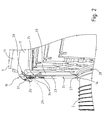
- reference numeral 1 indicates a portion of a gas turbine including a rotor ring 2 (only partially shown), which is centered on a longitudinal axis (not shown in the accompanying figures) and is coupled to a plurality of rotor blades 3 radially arranged about the rotor ring 2.
- the rotor ring 2 is provided with a plurality of essentially equally spaced seats 5, which axially extend along a peripheral edge 6 of the rotor ring 2.
- Each seat 5 is adapted to be engaged by an end portion 7 of a corresponding rotor blade 3 by means of a sliding prismatic coupling; specifically, each seat 5 has two side walls 8, respectively provided with three axial undercuts 9 adapted to prevent the movement of the end portion 7 of the blade 3 in the radial direction when the turbine 1 is running.
- Each blade 3 includes, as mentioned above, an end portion 7, a platform 11, integrally coupled to the end portion 7, and an elongated main body 12, which extends from the platform 11 at the opposite side with respect to the end portion 7.
- each blade 3 may be inserted in the corresponding seat 5 of the rotor ring 2 in a direction parallel to the axis of the rotor ring 2.
- the end portion 7 has a shape essentially complementary to the shape of the corresponding seat 5 of the rotor ring 2, but has a lower radial height than the radial height of the seat 5 so that, when the seat 5 is engaged, the end portion 7 forms a channel 14 for the passage of a cooling fluid, preferably air bled from the compressor (not shown) of the gas turbine 1.
- each blade 3 is further provided with one or more internal channels (not shown in the accompanying figures), which face the channel 14 and provide to cool the end portion 7 itself and to feed a complex system of cooling channels 15 (only one of which is partially shown in figure 1 ) of the main body 12.
- the platform 11 of each blade 3 has two axially opposite peripheral portions 19, which axially exceed with respect to the end portion 7.
- a peripheral portion 19 of the platform 11 is provided, on the side facing the end portion 7, with a circumferential groove 20.
- a variant (not shown) of the present invention provides for both peripheral portions 19 having a circumferential groove 20, on the side facing the end portion 7.
- each blade 3 includes a tip (not shown for simplicity in the accompanying figures), opposite to the end portion 7, a leading edge 16 and a trailing edge 17.
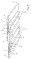
- the gas turbine 1 further includes a plurality of sealing elements 22 (only one of which is shown in figure 1 for simplicity), which are adapted to be coupled to the rotor ring 2 and to the blades 3 and arranged side-by-side in the circumferential direction to contribute to fasten the end portions 7 of the blades 3 in the axial direction and to correctly cool the end portions 7 of the blades 3.
- the sealing elements 22 are arranged side-by-side in the circumferential direction on only one annular face of the rotor ring 2.
- a variant (not shown) of the present invention provides for the sealing elements 22 being arranged side-by-side in the circumferential direction on both annular faces of the rotor ring 2.
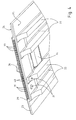
- each sealing element 22 includes an essentially rectangle-shaped wall 23, which has an external face 24 adapted to be arranged in use in contact with the hot working fluid in the turbine and an internal face 25 adapted to be arranged in use in contact with the cooling fluid from the channel 14.
- the wall 23 has an upper edge 26 adapted to engage the circumferential groove 20 of the platform 11 of at least one blade 3; in the example of the accompanying figures, the sealing element 22 is arranged straddled on two blades 3 and therefore the upper edge 26 engages the circumferential groove 20 of a blade 3 and the circumferential groove 20 of the adjacent blade 3.
- the wall 23 has a lower edge 27 adapted to engage a corresponding portion of a circumferential seat 28 made in the rotor ring 2.
- the wall 23 includes a gap 29, which is travelled through by the cooling fluid from the channel 14 and flowing in the space between the sealing element 22 and the end portion 7 of the blade 3 facing thereto.
- the gap 29 communicates with the hot working fluid in the gas turbine through one or more outlets 30 ( figures 1 and 3 ) made in the external face 24 close to the upper edge 26 and with the cooling fluid through one or more inlets 31 ( figure 3 ) made in the internal face 25 close to the upper edge 26.
- the inlets 31 and the outlets 30 are reciprocally and circumferentially offset.
- the outlets 30 are three holes, which are essentially adjacent and circular in section, while the inlets 31 are two holes, which are essentially adjacent and circular in section. It is understood that the number and/or shape and/or size of the inlets 31 which feed the gap 29 may be varied to calibrate the amount of cooling fluid as required (high performing machines, more or less thermally loaded turbine stages, etc.). Similarly, the number and/or shape and/or size of the outlets 30 may also be varied as required.
- the gap 29 is open at the upper edge 26 of the wall 23 and deeply extends into the wall 23 for a length preferably equal to about 1/25 of the total length of the wall 23, between the upper edge 26 and the lower edge 27.
- Each sealing element 22 further includes a plurality of ribs 33 and a blocking element 34.
- the ribs 33 extend from the internal face 25 of the wall 23, essentially for the entire length of the wall 23 between the upper edge 26 and the lower edge 27, are parallel to each other, and essentially orthogonal to the upper edge 26 of the wall 23.
- the ribs 33 act to structurally stiffen the sealing element 22 so as to make it sufficiently strong to support the action of the centrifugal force and the pressure difference to which the sealing element 22 is subjected when the gas turbine 1 is running.
- the blocking element 34 is essentially an elongated foil, integrally connected to the wall 23 of the sealing element 22 and having a tip-shaped end 36 adapted to be arranged in a corresponding seat 37.
- the shape of the seat 37 is complementary to the end 36 and is defined by the peripheral portions 19 of the platforms 11 of two adjacent blades 3.
- the blocking element 34 is C-folded to allow the passage of the blocking element 34 through two essentially adjacent slots 38, of the external face 24 of the wall 23.
- the blocking element 34 prevents the movement of the sealing element 22 in the circumferential direction.
- Figure 4 shows a variant of the sealing element 22, according to which the gap 29 is provided with a plurality of fins 39 which protrude from two corresponding internal faces 40 parallel to the internal face 25 of the wall 23 for increasing the heat exchange surface.
- the fins 39 are arranged transversally to the corresponding faces 40.
- the cooling fluid from the channels 14 of each blade 3 enters the gap 29 of each sealing element 22 through the inlets 31 and exits from the gap 29 through the outlets 30.
- the cooling fluid determines a cooling by convection of the area close to the upper edge 26 when passing inside the gap 29 (possibly increased by the presence of the fins 39) and a cooling by convection of the platform 11 of the rotor blades 3 and of the seat 37 of the blocking element 34 exiting from the outlets 30.
- the present invention has the following advantages.
- the disassembly interventions of the rotor blades 3 are easier, faster and most cost-effective because the correct cooling of the upper edge 26 of the sealing element 22 eliminates the problems related to plastic deformations of the upper edge 26.
- sealing element 22 it is possible to increase the operating temperature of the working fluid in the gas turbine 1 and, accordingly, increase the performance of the entire gas turbine 1.
- the production costs of the sealing element 22 may be reduced in virtue of the good cooling of the upper edge 26, reached by means of the particular shape of the sealing element 22, which no longer imposes the use of materials having high mechanical features.
- sealing element 22 is adapted to be installed on any type of gas turbine, also on previously installed gas turbines.
Abstract
Description
- The present invention relates to a sealing element for a gas turbine, to a gas turbine including said sealing element and to a method for cooling said sealing element.
- Gas turbines of known type generally include a rotating shaft, extending along a longitudinal axis, with a plurality of rotor rings connected thereto, each of which is centered on the longitudinal axis. Each rotor ring is coupled to a plurality of rotor blades radially arranged about the rotor ring.
- Specifically, each rotor ring is provided with a plurality of essentially equally spaced seats, which axially extend along the peripheral edge of the rotor ring. Each seat is adapted to be engaged by an end portion of a corresponding rotor blade by means of an axially sliding prismatic coupling. This type of coupling between the blade and the rotor ring ensures, when the turbine is running, an appropriate fastening of the blade in a radial direction, but allows the blade end portion to be displaced in the axial direction. Therefore, the axial movement of the end portions of the blades must be prevented. Such an object is generally reached by using sealing elements, which are circumferentially arranged side-by-side to essentially form a sealing ring and which are fixed to the rotor ring and to one or more rotor blades, on one or both of the annular faces of the rotor ring.
- The sealing elements further contribute to correctly cool the rotor blades because they protect the end portions of the rotor blades from the hot working fluid in the gas turbine. Each sealing element indeed includes a wall having an external face in contact with the hot working fluid in the gas turbine and an internal face in contact with the cooling fluid of the gas turbine. However, the sealing elements are often subjected to overheating, because the contact with the cooling fluid along the internal face is not sufficient to ensure an adequate cooling of the whole sealing element. Specifically, the sealing element is provided with an upper edge adapted to be coupled to the rotor blade, which is particularly subject to overheating because it is subjected to a fairy high heat load due to its position close to the flow area of the hot working fluid. Such an upper edge reaches very high temperatures and undergoes plastic deformations due to the overheating and to the simultaneous action of the centrifugal force which cause a sort of welding of the sealing element onto the rotor blade. This implies great difficulties, for example, during the operations of disassembling the sealing elements, because very often it is necessary to resort to operations which damage the sealing elements and risk damaging the rotor blade as well.
- It is an object of the present invention to make a sealing element which is free from the prior art drawbacks highlighted herein; specifically, it is an object of the invention to make a sealing element shaped so as to ensure an appropriate cooling of the upper edge while being easy and cost effective to be made.
- In accordance with these objects, the present invention relates to a sealing element for a gas turbine; the gas turbine including at least one rotor ring and at least a plurality of rotor blades radially arranged about the rotor ring and having an end portion fixed to the rotor ring; the sealing element including a wall which is coupled to the rotor ring and to at least one rotor blade and is provided with an external face in contact with a hot working fluid in the gas turbine and with an internal face in contact with a cooling fluid of the gas turbine;
the sealing element being characterized in that the wall has a gap which is adapted to be travelled through by the cooling fluid. - It is a further object of the present invention to make an efficient gas turbine. In accordance with such objects, the present invention further relates to a gas turbine including at least one rotor ring and at least a plurality of rotor blades radially arranged about the rotor ring and having an end portion fixed to the rotor ring; the gas turbine being characterized in that it includes at least one sealing element according to anyone of the claims from 1 to 15.
- It is a further object of the present invention to provide a simple and effective method for cooling a sealing element of a gas turbine. In accordance with these objects, the present invention relates to a method for cooling a sealing element for a gas turbine; the gas turbine including at least one rotor ring and at least a plurality of rotor blades radially arranged about the rotor ring and having an end portion fixed to the rotor ring; the sealing element including a wall, which is adapted to be coupled to the rotor ring and at least one rotor blade and is provided with an external face adapted to be arranged in contact with a hot working fluid in the gas turbine and with an internal face adapted to be arranged in contact with a cooling fluid in the gas turbine; the method being characterized in that it includes the step of conveying the cooling fluid into a gap of the wall of the sealing element.
- Further features and advantages of the present invention will be apparent from the following description of a non-limitative embodiment thereof, with reference to the figures in the accompanying drawings, in which:
-
figure 1 is a perspective view, with parts in section and parts removed for clarity, of a first detail of the gas turbine according to the present invention; -
figure 2 is a perspective view, with parts removed for clarity, of a second detail of the gas turbine according to the present invention; -
figure 3 is a perspective view of a sealing element according to the present invention; -
figure 4 is a perspective view, with parts removed for clarity, of a detail of a sealing element made according to a different embodiment of the present invention. - In
figure 1 , reference numeral 1 indicates a portion of a gas turbine including a rotor ring 2 (only partially shown), which is centered on a longitudinal axis (not shown in the accompanying figures) and is coupled to a plurality ofrotor blades 3 radially arranged about therotor ring 2. - The
rotor ring 2 is provided with a plurality of essentially equally spacedseats 5, which axially extend along aperipheral edge 6 of therotor ring 2. Eachseat 5 is adapted to be engaged by anend portion 7 of acorresponding rotor blade 3 by means of a sliding prismatic coupling; specifically, eachseat 5 has twoside walls 8, respectively provided with threeaxial undercuts 9 adapted to prevent the movement of theend portion 7 of theblade 3 in the radial direction when the turbine 1 is running. - Each
blade 3 includes, as mentioned above, anend portion 7, aplatform 11, integrally coupled to theend portion 7, and an elongatedmain body 12, which extends from theplatform 11 at the opposite side with respect to theend portion 7. - The
end portion 7 of eachblade 3 may be inserted in thecorresponding seat 5 of therotor ring 2 in a direction parallel to the axis of therotor ring 2. Specifically, theend portion 7 has a shape essentially complementary to the shape of thecorresponding seat 5 of therotor ring 2, but has a lower radial height than the radial height of theseat 5 so that, when theseat 5 is engaged, theend portion 7 forms achannel 14 for the passage of a cooling fluid, preferably air bled from the compressor (not shown) of the gas turbine 1. - The
end portion 7 of eachblade 3 is further provided with one or more internal channels (not shown in the accompanying figures), which face thechannel 14 and provide to cool theend portion 7 itself and to feed a complex system of cooling channels 15 (only one of which is partially shown infigure 1 ) of themain body 12. - The
platform 11 of eachblade 3 has two axially oppositeperipheral portions 19, which axially exceed with respect to theend portion 7. Aperipheral portion 19 of theplatform 11 is provided, on the side facing theend portion 7, with acircumferential groove 20. A variant (not shown) of the present invention provides for bothperipheral portions 19 having acircumferential groove 20, on the side facing theend portion 7. - The
main body 12 of eachblade 3 includes a tip (not shown for simplicity in the accompanying figures), opposite to theend portion 7, a leadingedge 16 and atrailing edge 17. - The gas turbine 1 further includes a plurality of sealing elements 22 (only one of which is shown in
figure 1 for simplicity), which are adapted to be coupled to therotor ring 2 and to theblades 3 and arranged side-by-side in the circumferential direction to contribute to fasten theend portions 7 of theblades 3 in the axial direction and to correctly cool theend portions 7 of theblades 3. In the non-limitative example shown in the accompanying figures, thesealing elements 22 are arranged side-by-side in the circumferential direction on only one annular face of therotor ring 2. A variant (not shown) of the present invention provides for the sealingelements 22 being arranged side-by-side in the circumferential direction on both annular faces of therotor ring 2. - With reference to
figures 1 and2 , eachsealing element 22 includes an essentially rectangle-shaped wall 23, which has anexternal face 24 adapted to be arranged in use in contact with the hot working fluid in the turbine and aninternal face 25 adapted to be arranged in use in contact with the cooling fluid from thechannel 14. - With reference to
figure 2 , thewall 23 has anupper edge 26 adapted to engage thecircumferential groove 20 of theplatform 11 of at least oneblade 3; in the example of the accompanying figures, the sealingelement 22 is arranged straddled on twoblades 3 and therefore theupper edge 26 engages thecircumferential groove 20 of ablade 3 and thecircumferential groove 20 of theadjacent blade 3. - The
wall 23 has alower edge 27 adapted to engage a corresponding portion of acircumferential seat 28 made in therotor ring 2. - With reference to
figures 2 and3 , thewall 23 includes agap 29, which is travelled through by the cooling fluid from thechannel 14 and flowing in the space between thesealing element 22 and theend portion 7 of theblade 3 facing thereto. - Specifically, the
gap 29 communicates with the hot working fluid in the gas turbine through one or more outlets 30 (figures 1 and3 ) made in theexternal face 24 close to theupper edge 26 and with the cooling fluid through one or more inlets 31 (figure 3 ) made in theinternal face 25 close to theupper edge 26. - The
inlets 31 and theoutlets 30 are reciprocally and circumferentially offset. - In the non-limiting example described and illustrated herein, the
outlets 30 are three holes, which are essentially adjacent and circular in section, while theinlets 31 are two holes, which are essentially adjacent and circular in section. It is understood that the number and/or shape and/or size of theinlets 31 which feed thegap 29 may be varied to calibrate the amount of cooling fluid as required (high performing machines, more or less thermally loaded turbine stages, etc.). Similarly, the number and/or shape and/or size of theoutlets 30 may also be varied as required. - In the non-limiting example described and illustrated herein, the
gap 29 is open at theupper edge 26 of thewall 23 and deeply extends into thewall 23 for a length preferably equal to about 1/25 of the total length of thewall 23, between theupper edge 26 and thelower edge 27. - Each
sealing element 22 further includes a plurality ofribs 33 and ablocking element 34. - The
ribs 33 extend from theinternal face 25 of thewall 23, essentially for the entire length of thewall 23 between theupper edge 26 and thelower edge 27, are parallel to each other, and essentially orthogonal to theupper edge 26 of thewall 23. Theribs 33 act to structurally stiffen the sealingelement 22 so as to make it sufficiently strong to support the action of the centrifugal force and the pressure difference to which the sealingelement 22 is subjected when the gas turbine 1 is running. - With reference to
figure 1 , theblocking element 34 is essentially an elongated foil, integrally connected to thewall 23 of thesealing element 22 and having a tip-shaped end 36 adapted to be arranged in acorresponding seat 37. The shape of theseat 37 is complementary to theend 36 and is defined by theperipheral portions 19 of theplatforms 11 of twoadjacent blades 3. Specifically, theblocking element 34 is C-folded to allow the passage of theblocking element 34 through two essentiallyadjacent slots 38, of theexternal face 24 of thewall 23. The blockingelement 34 prevents the movement of the sealingelement 22 in the circumferential direction. -
Figure 4 shows a variant of thesealing element 22, according to which thegap 29 is provided with a plurality offins 39 which protrude from two correspondinginternal faces 40 parallel to theinternal face 25 of thewall 23 for increasing the heat exchange surface. - In the example shown in
figure 4 , thefins 39 are arranged transversally to thecorresponding faces 40. - Once all the
sealing elements 22 have been coupled to thecorresponding blades 3 and to therotor ring 2, in use, the cooling fluid from thechannels 14 of eachblade 3 enters thegap 29 of eachsealing element 22 through theinlets 31 and exits from thegap 29 through theoutlets 30. The cooling fluid determines a cooling by convection of the area close to theupper edge 26 when passing inside the gap 29 (possibly increased by the presence of the fins 39) and a cooling by convection of theplatform 11 of therotor blades 3 and of theseat 37 of the blockingelement 34 exiting from theoutlets 30. - The present invention has the following advantages.
- Firstly, in virtue of the particular shape of the
sealing element 22 according to the present invention, the disassembly interventions of therotor blades 3 are easier, faster and most cost-effective because the correct cooling of theupper edge 26 of thesealing element 22 eliminates the problems related to plastic deformations of theupper edge 26. - Furthermore, in virtue of the
sealing element 22 according to the present invention, it is possible to increase the operating temperature of the working fluid in the gas turbine 1 and, accordingly, increase the performance of the entire gas turbine 1. - Additionally, the production costs of the sealing
element 22 may be reduced in virtue of the good cooling of theupper edge 26, reached by means of the particular shape of thesealing element 22, which no longer imposes the use of materials having high mechanical features. - Furthermore, the risks of failure of the whole gas turbine 1 caused be the sealing
element 22 exiting from its seat due to thermal-mechanical deformation is minimized. This further determines an increase of the time span between a maintenance intervention and the next of the sealingelements 22. - Finally, the sealing
element 22 according to the present invention is adapted to be installed on any type of gas turbine, also on previously installed gas turbines. - It is finally apparent that changes and variations may be made to the sealing element, to the gas turbine and to the method for cooling the sealing element described herein, without departing from the scope of the appended claims.
Claims (17)
- A sealing element (22) for a gas turbine (1); the gas turbine (1) including at least one rotor ring (2) and at least a plurality of rotor blades (3) radially arranged about the rotor ring (2) and having an end portion (7) fixed to the rotor ring (2); the sealing element (22) including a wall (23), which is adapted to be coupled to the rotor ring (2) and to at least one rotor blade (3) and is provided with an external face (24) adapted to be arranged in contact with a hot working fluid in the gas turbine (1) and with an internal face (25) adapted to be arranged in contact with a cooling fluid of the gas turbine (1);
the sealing element (22) being characterized in that the wall (23) has a gap (29), which is adapted to be travelled through by the cooling fluid. - An element according to claim 1, characterized in that the wall (23) has an upper edge (26) adapted to engage a corresponding circumferential groove (20) of a rotor blade (3); the gap (29) substantially extending close to the upper edge (26).
- An element according to anyone of the preceding claims, characterized in that the wall (23) has a lower edge (27) adapted to engage a circumferential seat (28) made in the rotor ring (2).
- An element according to claim 2 or 3, characterized in that the internal face (25) of the wall (23) is provided with at least one inlet (31) for feeding the gap (29) with the cooling fluid of the gas turbine (1).
- An element according to claim 4, characterized in that the inlet (31) is arranged on the internal face (25), essentially close to the upper edge (26).
- An element according to claim 4 or 5, characterized in that the external face (24) of the wall (23) is provided with at least one outlet (30) for communicating the gap (29) with the hot working fluid of the gas turbine (1).
- An element according to claim 6, characterized in that the outlet (30) is arranged on the external face (24), essentially close to the upper edge (26).
- An element according to claim 6 or 7, characterized in that the inlet (31) and the outlet (30) are circumferentially offset.
- An element according to anyone of the claims from 2 to 8, characterized in that the gap (29) is open at the upper edge (26) of the wall (23).
- An element according to anyone of the claims from 3 to 9, characterized in that the gap (29) deeply extends into the wall (23) for a length equal to about 1/25 of the entire length of the wall (23) between the upper edge (26) and the lower edge (27).
- An element according to anyone of the claims from 3 to 10, characterized in that it includes a plurality of ribs (33), which extend from the internal face (25) of the wall (23).
- An element according to claim 11, characterized in that the ribs (33) are parallel to each other and essentially orthogonal to the upper edge (26) of the wall (23); the ribs (33) essentially extending for the entire length of the wall (23) between the upper edge (26) and the lower edge (27).
- An element according to anyone of the claims from 2 to 12, characterized in that it includes a blocking element (34) integrally connected to the wall (23) of the sealing element (22) and having a tip-shaped end (36), adapted to be arranged in a corresponding seat (37) defined by two adjacent rotor blades (3).
- An element according to anyone of the claims from 2 to 13, characterized in that the gap (29) is provided with a plurality of fins (39) which extend from two corresponding internal faces (40) of the gap (29).
- An element according to claim 14, characterized in that the fins (39) are transversally arranged with respect to the corresponding faces (40).
- A gas turbine including at least one rotor ring (2) and at least a plurality of rotor blades (3) radially arranged about the rotor ring (2) and having an end portion (7) fixed to the rotor ring (2); the gas turbine (1) being characterized in that it includes at least one sealing element (22) according to anyone of the preceding claims.
- A method for cooling a sealing element (22) for a gas turbine (1); the gas turbine (1) including at least one rotor ring (2) and at least a plurality of rotor blades (3) radially arranged about the rotor ring (2) and having an end portion (7) fixed to the rotor ring (2); the sealing element (22) including a wall (23), which is adapted to be coupled to the rotor ring (2) and to at least one rotor blade (3) and is provided with an external face (24) adapted to be arranged in contact with a hot working fluid in the gas turbine (1) and with an internal face (25) adapted to be arranged in contact with a cooling fluid of the gas turbine (1); the method being characterized in that it includes the step of conveying the cooling fluid into a gap (29) of the wall (23) of the sealing element (22).
Priority Applications (3)
| Application Number | Priority Date | Filing Date | Title |
|---|---|---|---|
| EP08425486.1A EP2146055B2 (en) | 2008-07-17 | 2008-07-17 | Sealing element for a gas turbine, a gas turbine including said sealing element and method for cooling said sealing element |
| US12/499,950 US20100014986A1 (en) | 2008-07-17 | 2009-07-09 | Sealing element for a gas turbine, a gas turbine including said sealing element and method for cooling said sealing element |
| JP2009167852A JP2010025110A (en) | 2008-07-17 | 2009-07-16 | Sealing element for gas turbine, gas turbine including sealing element and method for cooling sealing element |
Applications Claiming Priority (1)
| Application Number | Priority Date | Filing Date | Title |
|---|---|---|---|
| EP08425486.1A EP2146055B2 (en) | 2008-07-17 | 2008-07-17 | Sealing element for a gas turbine, a gas turbine including said sealing element and method for cooling said sealing element |
Publications (3)
| Publication Number | Publication Date |
|---|---|
| EP2146055A1 true EP2146055A1 (en) | 2010-01-20 |
| EP2146055B1 EP2146055B1 (en) | 2012-11-28 |
| EP2146055B2 EP2146055B2 (en) | 2022-01-19 |
Family
ID=39959226
Family Applications (1)
| Application Number | Title | Priority Date | Filing Date |
|---|---|---|---|
| EP08425486.1A Active EP2146055B2 (en) | 2008-07-17 | 2008-07-17 | Sealing element for a gas turbine, a gas turbine including said sealing element and method for cooling said sealing element |
Country Status (3)
| Country | Link |
|---|---|
| US (1) | US20100014986A1 (en) |
| EP (1) | EP2146055B2 (en) |
| JP (1) | JP2010025110A (en) |
Cited By (1)
| Publication number | Priority date | Publication date | Assignee | Title |
|---|---|---|---|---|
| EP3070268A3 (en) * | 2015-03-20 | 2016-11-02 | Rolls-Royce plc | A bladed rotor arrangement and a lock plate for a bladed rotor arrangement and corresponding method of manufacturing |
Families Citing this family (7)
| Publication number | Priority date | Publication date | Assignee | Title |
|---|---|---|---|---|
| US8550785B2 (en) | 2010-06-11 | 2013-10-08 | Siemens Energy, Inc. | Wire seal for metering of turbine blade cooling fluids |
| JP6613611B2 (en) * | 2015-05-15 | 2019-12-04 | 株式会社Ihi | Turbine blade mounting structure |
| KR20180114765A (en) * | 2017-04-11 | 2018-10-19 | 두산중공업 주식회사 | Retainer for gas turbine blade, turbine unit and gas turbine using the same |
| DE102017109952A1 (en) * | 2017-05-09 | 2018-11-15 | Rolls-Royce Deutschland Ltd & Co Kg | Rotor device of a turbomachine |
| KR20190029963A (en) * | 2017-09-13 | 2019-03-21 | 두산중공업 주식회사 | Cooling structure of Turbine blade and turbine and gas turbine comprising the same |
| US10738626B2 (en) * | 2017-10-24 | 2020-08-11 | General Electric Company | Connection assemblies between turbine rotor blades and rotor wheels |
| US11555407B2 (en) | 2020-05-19 | 2023-01-17 | General Electric Company | Turbomachine rotor assembly |
Citations (4)
| Publication number | Priority date | Publication date | Assignee | Title |
|---|---|---|---|---|
| US3834831A (en) * | 1973-01-23 | 1974-09-10 | Westinghouse Electric Corp | Blade shank cooling arrangement |
| EP0801208A2 (en) * | 1996-04-12 | 1997-10-15 | United Technologies Corporation | Cooled rotor assembly for a turbine engine |
| US6065932A (en) * | 1997-07-11 | 2000-05-23 | Rolls-Royce Plc | Turbine |
| DE19950109A1 (en) * | 1999-10-18 | 2001-04-19 | Asea Brown Boveri | Rotor for a gas turbine |
Family Cites Families (9)
| Publication number | Priority date | Publication date | Assignee | Title |
|---|---|---|---|---|
| US3728042A (en) * | 1971-08-27 | 1973-04-17 | Westinghouse Electric Corp | Axial positioner and seal for cooled rotor blade |
| US3834381A (en) * | 1972-08-25 | 1974-09-10 | Puritan Bennett Corp | Compliance compensated ventilation system |
| US5755556A (en) * | 1996-05-17 | 1998-05-26 | Westinghouse Electric Corporation | Turbomachine rotor with improved cooling |
| DE50002464D1 (en) † | 1999-06-28 | 2003-07-10 | Siemens Ag | HOT GAS ADDABLE COMPONENT, ESPECIALLY TURBINE BLADE |
| US8105041B2 (en) † | 2005-09-07 | 2012-01-31 | Siemens Aktiengesellschaft | Arrangement for axially securing rotating blades in a rotor, sealing element for such an arrangement, and use of such an arrangement |
| US7371044B2 (en) † | 2005-10-06 | 2008-05-13 | Siemens Power Generation, Inc. | Seal plate for turbine rotor assembly between turbine blade and turbine vane |
| US7465149B2 (en) * | 2006-03-14 | 2008-12-16 | Rolls-Royce Plc | Turbine engine cooling |
| US7566201B2 (en) * | 2007-01-30 | 2009-07-28 | Siemens Energy, Inc. | Turbine seal plate locking system |
| US8128371B2 (en) † | 2007-02-15 | 2012-03-06 | General Electric Company | Method and apparatus to facilitate increasing turbine rotor efficiency |
-
2008
- 2008-07-17 EP EP08425486.1A patent/EP2146055B2/en active Active
-
2009
- 2009-07-09 US US12/499,950 patent/US20100014986A1/en not_active Abandoned
- 2009-07-16 JP JP2009167852A patent/JP2010025110A/en not_active Withdrawn
Patent Citations (4)
| Publication number | Priority date | Publication date | Assignee | Title |
|---|---|---|---|---|
| US3834831A (en) * | 1973-01-23 | 1974-09-10 | Westinghouse Electric Corp | Blade shank cooling arrangement |
| EP0801208A2 (en) * | 1996-04-12 | 1997-10-15 | United Technologies Corporation | Cooled rotor assembly for a turbine engine |
| US6065932A (en) * | 1997-07-11 | 2000-05-23 | Rolls-Royce Plc | Turbine |
| DE19950109A1 (en) * | 1999-10-18 | 2001-04-19 | Asea Brown Boveri | Rotor for a gas turbine |
Cited By (2)
| Publication number | Priority date | Publication date | Assignee | Title |
|---|---|---|---|---|
| EP3070268A3 (en) * | 2015-03-20 | 2016-11-02 | Rolls-Royce plc | A bladed rotor arrangement and a lock plate for a bladed rotor arrangement and corresponding method of manufacturing |
| US10041362B2 (en) | 2015-03-20 | 2018-08-07 | Rolls-Royce Plc | Bladed rotor arrangement and a lock plate for a bladed rotor arrangement |
Also Published As
| Publication number | Publication date |
|---|---|
| US20100014986A1 (en) | 2010-01-21 |
| JP2010025110A (en) | 2010-02-04 |
| EP2146055B1 (en) | 2012-11-28 |
| EP2146055B2 (en) | 2022-01-19 |
Similar Documents
| Publication | Publication Date | Title |
|---|---|---|
| EP2146055B1 (en) | Sealing element for a gas turbine, a gas turbine including said sealing element and method for cooling said sealing element | |
| US8920121B2 (en) | Axial turbomachine rotor having a sealing disk | |
| EP3093449B1 (en) | Shroud retention system with retention springs | |
| AU2012203822B9 (en) | Turbine vane | |
| EP2951396B1 (en) | Gas turbine rotor blade and gas turbine rotor | |
| EP3043029B1 (en) | Fixture and method for installing turbine buckets | |
| US20160090854A1 (en) | Bladed rotor arrangement | |
| KR20110136894A (en) | Rotor section for a rotor of a turbomachine | |
| US20150322796A1 (en) | Turbine rotor for a turbomachine | |
| CA2929159A1 (en) | Shroud retention system with keyed retention clips | |
| US9745852B2 (en) | Axial rotor portion and turbine rotor blade for a gas turbine | |
| EP2400116A2 (en) | Sealing device of a blade root | |
| EP3002411B1 (en) | A bladed rotor arrangement with lock plates having deformable feet | |
| US20120134778A1 (en) | Axial flow gas turbine | |
| US8926269B2 (en) | Stepped, conical honeycomb seal carrier | |
| US10385706B2 (en) | Rotary assembly for a turbomachine | |
| US8591192B2 (en) | Turbomachine rotor assembly and method | |
| US20170314400A1 (en) | Hollow blade body, insertion rib, and hollow blade | |
| US9945240B2 (en) | Power turbine heat shield architecture | |
| JP6110035B2 (en) | Rotor of thermal turbomachine | |
| US9657641B2 (en) | Fluid flow machine especially gas turbine penetrated axially by a hot gas stream | |
| EP2146051B1 (en) | Rotor assembly for a gas turbine, gas turbine including said rotor assembly and method for cooling said rotor assembly | |
| JP2010535968A (en) | Turbine rotor mechanism | |
| EP2855888B1 (en) | Segmented seal with ship lap ends | |
| US20120070310A1 (en) | Axial turbomachine rotor having blade cooling |
Legal Events
| Date | Code | Title | Description |
|---|---|---|---|
| PUAI | Public reference made under article 153(3) epc to a published international application that has entered the european phase |
Free format text: ORIGINAL CODE: 0009012 |
|
| AK | Designated contracting states |
Kind code of ref document: A1 Designated state(s): AT BE BG CH CY CZ DE DK EE ES FI FR GB GR HR HU IE IS IT LI LT LU LV MC MT NL NO PL PT RO SE SI SK TR |
|
| AX | Request for extension of the european patent |
Extension state: AL BA MK RS |
|
| 17P | Request for examination filed |
Effective date: 20100720 |
|
| AKX | Designation fees paid |
Designated state(s): AT BE BG CH CY CZ DE DK EE ES FI FR GB GR HR HU IE IS IT LI LT LU LV MC MT NL NO PL PT RO SE SI SK TR |
|
| 17Q | First examination report despatched |
Effective date: 20110909 |
|
| REG | Reference to a national code |
Ref country code: DE Ref legal event code: R079 Ref document number: 602008020384 Country of ref document: DE Free format text: PREVIOUS MAIN CLASS: F01D0005300000 Ipc: F01D0005080000 |
|
| RIC1 | Information provided on ipc code assigned before grant |
Ipc: F01D 11/00 20060101ALI20120502BHEP Ipc: F01D 25/12 20060101ALI20120502BHEP Ipc: F01D 5/30 20060101ALI20120502BHEP Ipc: F01D 5/08 20060101AFI20120502BHEP |
|
| GRAP | Despatch of communication of intention to grant a patent |
Free format text: ORIGINAL CODE: EPIDOSNIGR1 |
|
| GRAS | Grant fee paid |
Free format text: ORIGINAL CODE: EPIDOSNIGR3 |
|
| GRAA | (expected) grant |
Free format text: ORIGINAL CODE: 0009210 |
|
| STAA | Information on the status of an ep patent application or granted ep patent |
Free format text: STATUS: THE PATENT HAS BEEN GRANTED |
|
| AK | Designated contracting states |
Kind code of ref document: B1 Designated state(s): AT BE BG CH CY CZ DE DK EE ES FI FR GB GR HR HU IE IS IT LI LT LU LV MC MT NL NO PL PT RO SE SI SK TR |
|
| REG | Reference to a national code |
Ref country code: GB Ref legal event code: FG4D |
|
| REG | Reference to a national code |
Ref country code: CH Ref legal event code: EP |
|
| REG | Reference to a national code |
Ref country code: AT Ref legal event code: REF Ref document number: 586299 Country of ref document: AT Kind code of ref document: T Effective date: 20121215 |
|
| REG | Reference to a national code |
Ref country code: IE Ref legal event code: FG4D |
|
| REG | Reference to a national code |
Ref country code: DE Ref legal event code: R096 Ref document number: 602008020384 Country of ref document: DE Effective date: 20130124 |
|
| REG | Reference to a national code |
Ref country code: AT Ref legal event code: MK05 Ref document number: 586299 Country of ref document: AT Kind code of ref document: T Effective date: 20121128 |
|
| REG | Reference to a national code |
Ref country code: NL Ref legal event code: VDEP Effective date: 20121128 |
|
| REG | Reference to a national code |
Ref country code: LT Ref legal event code: MG4D |
|
| PG25 | Lapsed in a contracting state [announced via postgrant information from national office to epo] |
Ref country code: LT Free format text: LAPSE BECAUSE OF FAILURE TO SUBMIT A TRANSLATION OF THE DESCRIPTION OR TO PAY THE FEE WITHIN THE PRESCRIBED TIME-LIMIT Effective date: 20121128 Ref country code: ES Free format text: LAPSE BECAUSE OF FAILURE TO SUBMIT A TRANSLATION OF THE DESCRIPTION OR TO PAY THE FEE WITHIN THE PRESCRIBED TIME-LIMIT Effective date: 20130311 Ref country code: SE Free format text: LAPSE BECAUSE OF FAILURE TO SUBMIT A TRANSLATION OF THE DESCRIPTION OR TO PAY THE FEE WITHIN THE PRESCRIBED TIME-LIMIT Effective date: 20121128 Ref country code: NO Free format text: LAPSE BECAUSE OF FAILURE TO SUBMIT A TRANSLATION OF THE DESCRIPTION OR TO PAY THE FEE WITHIN THE PRESCRIBED TIME-LIMIT Effective date: 20130228 Ref country code: FI Free format text: LAPSE BECAUSE OF FAILURE TO SUBMIT A TRANSLATION OF THE DESCRIPTION OR TO PAY THE FEE WITHIN THE PRESCRIBED TIME-LIMIT Effective date: 20121128 |
|
| PG25 | Lapsed in a contracting state [announced via postgrant information from national office to epo] |
Ref country code: PL Free format text: LAPSE BECAUSE OF FAILURE TO SUBMIT A TRANSLATION OF THE DESCRIPTION OR TO PAY THE FEE WITHIN THE PRESCRIBED TIME-LIMIT Effective date: 20121128 Ref country code: LV Free format text: LAPSE BECAUSE OF FAILURE TO SUBMIT A TRANSLATION OF THE DESCRIPTION OR TO PAY THE FEE WITHIN THE PRESCRIBED TIME-LIMIT Effective date: 20121128 Ref country code: BE Free format text: LAPSE BECAUSE OF FAILURE TO SUBMIT A TRANSLATION OF THE DESCRIPTION OR TO PAY THE FEE WITHIN THE PRESCRIBED TIME-LIMIT Effective date: 20121128 Ref country code: GR Free format text: LAPSE BECAUSE OF FAILURE TO SUBMIT A TRANSLATION OF THE DESCRIPTION OR TO PAY THE FEE WITHIN THE PRESCRIBED TIME-LIMIT Effective date: 20130301 Ref country code: PT Free format text: LAPSE BECAUSE OF FAILURE TO SUBMIT A TRANSLATION OF THE DESCRIPTION OR TO PAY THE FEE WITHIN THE PRESCRIBED TIME-LIMIT Effective date: 20130328 Ref country code: SI Free format text: LAPSE BECAUSE OF FAILURE TO SUBMIT A TRANSLATION OF THE DESCRIPTION OR TO PAY THE FEE WITHIN THE PRESCRIBED TIME-LIMIT Effective date: 20121128 |
|
| PG25 | Lapsed in a contracting state [announced via postgrant information from national office to epo] |
Ref country code: AT Free format text: LAPSE BECAUSE OF FAILURE TO SUBMIT A TRANSLATION OF THE DESCRIPTION OR TO PAY THE FEE WITHIN THE PRESCRIBED TIME-LIMIT Effective date: 20121128 |
|
| PG25 | Lapsed in a contracting state [announced via postgrant information from national office to epo] |
Ref country code: BG Free format text: LAPSE BECAUSE OF FAILURE TO SUBMIT A TRANSLATION OF THE DESCRIPTION OR TO PAY THE FEE WITHIN THE PRESCRIBED TIME-LIMIT Effective date: 20130228 Ref country code: EE Free format text: LAPSE BECAUSE OF FAILURE TO SUBMIT A TRANSLATION OF THE DESCRIPTION OR TO PAY THE FEE WITHIN THE PRESCRIBED TIME-LIMIT Effective date: 20121128 Ref country code: DK Free format text: LAPSE BECAUSE OF FAILURE TO SUBMIT A TRANSLATION OF THE DESCRIPTION OR TO PAY THE FEE WITHIN THE PRESCRIBED TIME-LIMIT Effective date: 20121128 Ref country code: SK Free format text: LAPSE BECAUSE OF FAILURE TO SUBMIT A TRANSLATION OF THE DESCRIPTION OR TO PAY THE FEE WITHIN THE PRESCRIBED TIME-LIMIT Effective date: 20121128 Ref country code: CZ Free format text: LAPSE BECAUSE OF FAILURE TO SUBMIT A TRANSLATION OF THE DESCRIPTION OR TO PAY THE FEE WITHIN THE PRESCRIBED TIME-LIMIT Effective date: 20121128 |
|
| PG25 | Lapsed in a contracting state [announced via postgrant information from national office to epo] |
Ref country code: RO Free format text: LAPSE BECAUSE OF FAILURE TO SUBMIT A TRANSLATION OF THE DESCRIPTION OR TO PAY THE FEE WITHIN THE PRESCRIBED TIME-LIMIT Effective date: 20121128 Ref country code: NL Free format text: LAPSE BECAUSE OF FAILURE TO SUBMIT A TRANSLATION OF THE DESCRIPTION OR TO PAY THE FEE WITHIN THE PRESCRIBED TIME-LIMIT Effective date: 20121128 |
|
| PLBI | Opposition filed |
Free format text: ORIGINAL CODE: 0009260 |
|
| 26 | Opposition filed |
Opponent name: SIEMENS AKTIENGESELLSCHAFT Effective date: 20130827 |
|
| PLAX | Notice of opposition and request to file observation + time limit sent |
Free format text: ORIGINAL CODE: EPIDOSNOBS2 |
|
| REG | Reference to a national code |
Ref country code: DE Ref legal event code: R026 Ref document number: 602008020384 Country of ref document: DE Effective date: 20130827 |
|
| PG25 | Lapsed in a contracting state [announced via postgrant information from national office to epo] |
Ref country code: CY Free format text: LAPSE BECAUSE OF FAILURE TO SUBMIT A TRANSLATION OF THE DESCRIPTION OR TO PAY THE FEE WITHIN THE PRESCRIBED TIME-LIMIT Effective date: 20121128 |
|
| PG25 | Lapsed in a contracting state [announced via postgrant information from national office to epo] |
Ref country code: HR Free format text: LAPSE BECAUSE OF FAILURE TO SUBMIT A TRANSLATION OF THE DESCRIPTION OR TO PAY THE FEE WITHIN THE PRESCRIBED TIME-LIMIT Effective date: 20130731 |
|
| PLAF | Information modified related to communication of a notice of opposition and request to file observations + time limit |
Free format text: ORIGINAL CODE: EPIDOSCOBS2 |
|
| PG25 | Lapsed in a contracting state [announced via postgrant information from national office to epo] |
Ref country code: MC Free format text: LAPSE BECAUSE OF FAILURE TO SUBMIT A TRANSLATION OF THE DESCRIPTION OR TO PAY THE FEE WITHIN THE PRESCRIBED TIME-LIMIT Effective date: 20121128 |
|
| REG | Reference to a national code |
Ref country code: CH Ref legal event code: PL |
|
| PLBB | Reply of patent proprietor to notice(s) of opposition received |
Free format text: ORIGINAL CODE: EPIDOSNOBS3 |
|
| REG | Reference to a national code |
Ref country code: IE Ref legal event code: MM4A |
|
| PG25 | Lapsed in a contracting state [announced via postgrant information from national office to epo] |
Ref country code: CH Free format text: LAPSE BECAUSE OF NON-PAYMENT OF DUE FEES Effective date: 20130731 Ref country code: LI Free format text: LAPSE BECAUSE OF NON-PAYMENT OF DUE FEES Effective date: 20130731 |
|
| PG25 | Lapsed in a contracting state [announced via postgrant information from national office to epo] |
Ref country code: IE Free format text: LAPSE BECAUSE OF NON-PAYMENT OF DUE FEES Effective date: 20130717 |
|
| PG25 | Lapsed in a contracting state [announced via postgrant information from national office to epo] |
Ref country code: TR Free format text: LAPSE BECAUSE OF FAILURE TO SUBMIT A TRANSLATION OF THE DESCRIPTION OR TO PAY THE FEE WITHIN THE PRESCRIBED TIME-LIMIT Effective date: 20121128 Ref country code: MT Free format text: LAPSE BECAUSE OF FAILURE TO SUBMIT A TRANSLATION OF THE DESCRIPTION OR TO PAY THE FEE WITHIN THE PRESCRIBED TIME-LIMIT Effective date: 20121128 |
|
| PG25 | Lapsed in a contracting state [announced via postgrant information from national office to epo] |
Ref country code: LU Free format text: LAPSE BECAUSE OF NON-PAYMENT OF DUE FEES Effective date: 20130717 Ref country code: HU Free format text: LAPSE BECAUSE OF FAILURE TO SUBMIT A TRANSLATION OF THE DESCRIPTION OR TO PAY THE FEE WITHIN THE PRESCRIBED TIME-LIMIT; INVALID AB INITIO Effective date: 20080717 |
|
| REG | Reference to a national code |
Ref country code: FR Ref legal event code: PLFP Year of fee payment: 9 |
|
| PG25 | Lapsed in a contracting state [announced via postgrant information from national office to epo] |
Ref country code: IS Free format text: LAPSE BECAUSE OF FAILURE TO SUBMIT A TRANSLATION OF THE DESCRIPTION OR TO PAY THE FEE WITHIN THE PRESCRIBED TIME-LIMIT Effective date: 20121128 |
|
| PLCK | Communication despatched that opposition was rejected |
Free format text: ORIGINAL CODE: EPIDOSNREJ1 |
|
| APBM | Appeal reference recorded |
Free format text: ORIGINAL CODE: EPIDOSNREFNO |
|
| APBP | Date of receipt of notice of appeal recorded |
Free format text: ORIGINAL CODE: EPIDOSNNOA2O |
|
| APAH | Appeal reference modified |
Free format text: ORIGINAL CODE: EPIDOSCREFNO |
|
| APBQ | Date of receipt of statement of grounds of appeal recorded |
Free format text: ORIGINAL CODE: EPIDOSNNOA3O |
|
| REG | Reference to a national code |
Ref country code: FR Ref legal event code: PLFP Year of fee payment: 10 |
|
| PLAB | Opposition data, opponent's data or that of the opponent's representative modified |
Free format text: ORIGINAL CODE: 0009299OPPO |
|
| R26 | Opposition filed (corrected) |
Opponent name: SIEMENS AKTIENGESELLSCHAFT Effective date: 20130827 |
|
| REG | Reference to a national code |
Ref country code: FR Ref legal event code: PLFP Year of fee payment: 11 |
|
| APBU | Appeal procedure closed |
Free format text: ORIGINAL CODE: EPIDOSNNOA9O |
|
| PLAO | Information deleted related to despatch of communication that opposition is rejected |
Free format text: ORIGINAL CODE: EPIDOSDREJ1 |
|
| STAA | Information on the status of an ep patent application or granted ep patent |
Free format text: STATUS: THE PATENT HAS BEEN GRANTED |
|
| PLAY | Examination report in opposition despatched + time limit |
Free format text: ORIGINAL CODE: EPIDOSNORE2 |
|
| PLAT | Information related to reply to examination report in opposition deleted |
Free format text: ORIGINAL CODE: EPIDOSDORE3 |
|
| PLBC | Reply to examination report in opposition received |
Free format text: ORIGINAL CODE: EPIDOSNORE3 |
|
| PLBC | Reply to examination report in opposition received |
Free format text: ORIGINAL CODE: EPIDOSNORE3 |
|
| PUAH | Patent maintained in amended form |
Free format text: ORIGINAL CODE: 0009272 |
|
| STAA | Information on the status of an ep patent application or granted ep patent |
Free format text: STATUS: PATENT MAINTAINED AS AMENDED |
|
| 27A | Patent maintained in amended form |
Effective date: 20220119 |
|
| AK | Designated contracting states |
Kind code of ref document: B2 Designated state(s): AT BE BG CH CY CZ DE DK EE ES FI FR GB GR HR HU IE IS IT LI LT LU LV MC MT NL NO PL PT RO SE SI SK TR |
|
| REG | Reference to a national code |
Ref country code: DE Ref legal event code: R102 Ref document number: 602008020384 Country of ref document: DE |
|
| PGFP | Annual fee paid to national office [announced via postgrant information from national office to epo] |
Ref country code: GB Payment date: 20231220 Year of fee payment: 16 |
|
| PGFP | Annual fee paid to national office [announced via postgrant information from national office to epo] |
Ref country code: IT Payment date: 20231228 Year of fee payment: 16 Ref country code: FR Payment date: 20231221 Year of fee payment: 16 Ref country code: DE Payment date: 20231214 Year of fee payment: 16 |