EP2145847B1 - Zellenradschleuse - Google Patents
Zellenradschleuse Download PDFInfo
- Publication number
- EP2145847B1 EP2145847B1 EP20090006637 EP09006637A EP2145847B1 EP 2145847 B1 EP2145847 B1 EP 2145847B1 EP 20090006637 EP20090006637 EP 20090006637 EP 09006637 A EP09006637 A EP 09006637A EP 2145847 B1 EP2145847 B1 EP 2145847B1
- Authority
- EP
- European Patent Office
- Prior art keywords
- cellular wheel
- housing
- logic circuit
- sluice according
- cellular
- Prior art date
- Legal status (The legal status is an assumption and is not a legal conclusion. Google has not performed a legal analysis and makes no representation as to the accuracy of the status listed.)
- Active
Links
Images



Classifications
-
- B—PERFORMING OPERATIONS; TRANSPORTING
- B65—CONVEYING; PACKING; STORING; HANDLING THIN OR FILAMENTARY MATERIAL
- B65G—TRANSPORT OR STORAGE DEVICES, e.g. CONVEYORS FOR LOADING OR TIPPING, SHOP CONVEYOR SYSTEMS OR PNEUMATIC TUBE CONVEYORS
- B65G53/00—Conveying materials in bulk through troughs, pipes or tubes by floating the materials or by flow of gas, liquid or foam
- B65G53/34—Details
- B65G53/40—Feeding or discharging devices
- B65G53/46—Gates or sluices, e.g. rotary wheels
- B65G53/4608—Turnable elements, e.g. rotary wheels with pockets or passages for material
- B65G53/4625—Turnable elements, e.g. rotary wheels with pockets or passages for material with axis of turning perpendicular to flow
- B65G53/4633—Turnable elements, e.g. rotary wheels with pockets or passages for material with axis of turning perpendicular to flow the element having pockets, rotated from charging position to discharging position, i.e. discrete flow
Definitions
- the invention relates to a rotary valve with a cellular wheel housing and a cellular wheel.
- an additional contact socket can be used with a logic circuit when using a rotary valve with a cell wheel and a cellular wheel of electrically conductive material for reliable detection of unwanted mechanical contact between the cell and the cellular.
- the ohmic resistance component prevents the cellular wheel or the cellular wheel housing from being charged with undesirable electrostatic charges during operation.
- the star feeder can have unilaterally or bilaterally couplings for the non-rotatable connection with one stub shaft each. This facilitates disassembly of the cell wheel, for example, for maintenance work following detection of an undesirable additional contact.
- the logic circuit can detect the additional contact even during a standstill of the cell wheel in addition to an additional contact detection in circulating operation of the cell wheel. This is used in particular for quality assurance purposes.
- a logic circuit according to claim 2 can in particular indicate the presence of an additional electrical contact, when the ohmic resistance falls below a predetermined limit. Such a condition for the presence of an additional electrical contact can be easily monitored. The detection can be done on the ohmic resistance component by measuring in particular a DC voltage drop at this and is safe to operate and can be evaluated sensitive.
- a rotational speed sensor By using a rotational speed sensor according to claim 3, a correlation of a detected additional contact with the rotational speed to avoid misjudgment of the electrical additional contact is ensured. Such misconceptions may arise, for example, due to moisture of the bulk material to be metered with the rotary valve.
- the speed sensor can be designed, for example, inductively.
- Embodiments of insulation units according to claims 4 to 9 have proven to be reliable and stable.
- the at least one insulation ring according to claim 6 can be made of plastic, in particular PA 6, for example.
- the at least one insulation ring can supplement the insulation layer in the region of radially extending peripheral stages of the cellular wheel shaft. It can also be provided several such isolation rings.
- the insulating sleeve according to claim 7 may also be made of plastic and, for example, POM.
- the Insulation layer on the drive-side shaft portion according to claim 8 may be designed as a ceramic coating.
- the feather key according to claim 9 can also be made of plastic and, for example, PEEK.
- the slip ring assembly may, for example, have eight mutually independent ring contacts.
- a data memory according to claim 11 allows a subsequent evaluation in particular of the time course of detected additional contact measurements. A statistical evaluation is also possible.
- An integration of the logic circuit according to claim 12 facilitates disassembly of the rotary valve.
- An additional contact indicator according to claim 13 is easy to read.
- An embodiment of the logic circuit according to claim 14 enables detection of actually relevant contacts of the cell wheel on the cellular wheel housing, without irrelevant measurement events being erroneously displayed as relevant additional contacts.
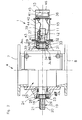
- Fig. 1 shows a schematic exploded view of a principle of operation of a detection device 1 for detecting an undesired contact between a cellular wheel 2 and a cellular wheel 3.
- the cellular 2 and the cellular wheel 3 are Bestanteile a total of 4 designated rotary valve.
- the cellular wheel 2 is inserted into a cylindrical receiving space 5 in the cell wheel housing 3.
- the receiving space 5 connects an inlet 7 of the rotary valve 4 with an outlet. 8
- the detection device 1 is not limited to the type of rotary feeder shown in the drawing, but can also be used in other known variants of rotary valves, for example in blow-by locks.
- the cellular wheel housing 3 is electrically connected via a signal line 9 to a detection module 10 of the detection device 1.
- a detection module 10 of the detection device 1 In the detection module 10, a logic circuit to be described is housed.
- the detection module 10 is housed in the cellular wheel housing 3 when the rotary valve 4 is mounted.
- the detection module 10 with the logic circuit is combined in the region of the stub shaft 13 within the cell housing 3 to form an assembly.
- the slip ring assembly 11 may have a plurality of independent ring contacts, so that in the event that one of these ring contacts fails, at least one other of these independent ring contacts continues to be a safe electrical contact between the feeder 2 and the signal line 15 via the slip ring assembly 11 is given.
- the slip ring assembly 11 may, for example, have eight independent ring contacts.
- a voltage drop is measured at an ohmic resistance component mounted on the logic circuit, which will be described later.
- the resistor component is connected between the two signal lines 9 and 15.
- an additional electrical contact between the Zellenradgeophuse 3 and the cellular 2 in addition to the electrical contact via the signal lines 9 and 15, this leads to a characteristic change of measured via the resistor component ohmic resistance.
- the unwanted additional contact is in the Fig. 1 schematically indicated by a dashed line 16a.
- the logic circuit of the detection module 10 outputs via output lines 16, 17, for example, an additional contact detection signal when the ohmic resistance measured on the ohmic resistance component due to the additional contact 16a falls below a predetermined limit.
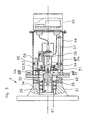
- Fig. 2 shows details of a first embodiment of the rotary valve 4.
- the bucket 2 has a drive-side Zellenradwellenabrough in the form of a drive shaft stub 18 which is rotatably connected to a not shown in the drawing cellular wheel drive.
- the cellular wheel 2 in the region of the drive shaft stub 18 is electrically isolated from a drive shaft of the cellular wheel drive, not shown.
- an electrical insulation unit 19 is used.
- This has a ceramic coating 20 on the jacket wall of the drive stub shaft 18 as an electrical insulation layer.
- a feather key 21 which in a slot recess 22 (see. Fig. 5 ) is inserted in the drive shaft stub 18.
- the key 21 is made of plastic and in the described embodiment of PEEK (polyetheretherketone).
- the feather key 21 is likewise a component of the insulation unit 19.
- a further electrical insulation unit 23 is used for electrical insulation of the drive shaft stub 18 with respect to a bearing-side housing section in the form of a side cover section 25 arranged in the region of a bearing 24 of the drive stub shaft 18 on the cellular wheel housing 3.
- the ceramic coating 20 belongs to this further insulation unit 23 is guided on the drive shaft stub 18 to the bearing section.
- the insulating unit 23 includes a pair of insulation rings 26, 27. These are axially spaced from each other on the drive shaft stub 18 in the region of the bearing 24, wherein between the insulation rings 26, 27, a shaft-fixed bearing member 28 is arranged.
- the two insulation rings 26, 27 are also made of plastic and in the described embodiment of PA (polyamide), in particular PA 6.
- the bearing 24 is fixed axially with a mounting ring 28a on the housing portion 25, wherein a temperature-induced length compensation is ensured.
- a housing-fixed bearing part of the bearing 24 is received in the housing portion 25 between the mounting ring 28a and a peripheral stage. Axially at the same height is the wave-proof Bearing part 28 am in the Fig. 2 right isolation ring 27 on.
- the insulating ring 27 is mounted in the region of a peripheral stage of the drive shaft stub 18, which is also referred to as a shaft shoulder.
- An opposite end of the drive shaft stub 18 counter stub 29 is mounted on a further bearing 30 at a further bearing-side housing portion in the form of another side cover portion 31 of the cellular housing 3.
- the two stub shafts, so the drive shaft stub 18 and the counter-stub shaft 29, take the bucket 2 between them.
- the two housing-side side cover of the Wellenradschleuse 4 with the side cover sections 25, 31 are arranged, which, as already mentioned above, the metering chambers between adjacent Also limit wings 6 of the bucket 2.
- bearing-side components components which are located in the area of the countershaft stub 29, that is, opposite the starwheel drive, are referred to as "bearing-side components".
- Insulating unit 32 is used for electrical insulation of the counter-shaft stub 29 relative to the bearing-side housing portion 31.
- Insulating unit 32 first includes an insulating layer in the form of a ceramic coating 33 on the mantle wall of the countershaft stub 29 in the axial region of the bearing 30.
- the insulating unit 32 further includes a pair of insulating rings 34, 35 which are insulated on the ceramic coating 33 Counter shaft stub 29 are axially spaced from each other and between which a shaft-fixed bearing member 36 of the bearing 30 is disposed.
- the insulating rings 34, 35 are made of the same material as the insulating rings 26, 27.
- the bearing 30 is axially fixed with a fastening nut 36a via a thread on the counter-shaft stub 29 and a peripheral step 36b in the housing section 31, ie a housing shoulder
- a thermal length compensation is guaranteed.
- Isolation ring 34 shown on the left are discs or disc springs 36 c arranged for the axial fixation of the bearing 30.
- the two insulating rings 34, 35 are used in accordance with what was outlined above to the insulating rings 26 and 27, in turn for electrically insulating radially extending peripheral stages, ie shaft paragraphs of the counter-shaft stub 29.
- the isolation ring 35 is between the mounting nut 36a and the shaft fixed bearing member 36th arranged.
- the counter-shaft stub 29 continues until the slip ring assembly 11.
- the housing-fixed slip ring component 12 is fixed by a retaining pin 37 on the cellular wheel housing 3.
- Fig. 6 shows the counter-shaft stub 29, wherein the extension towards the slip ring assembly 11 forming adapter sleeve is omitted. Shown is in particular the ceramic coating 33.
- the accommodated in the detection module 10 logic circuit 38 (see. Fig. 2 ) is connected to a speed sensor 39 for determining a rotational speed of the cell wheel 2 in the cellular housing 3 via a signal line 40 and a speed-evaluation circuit 41 in signal connection.
- the speed sensor 39 is fixed to a housing-fixed holding arm 42, which also carries the retaining pin 37.
- the speed sensor 39 interacts inductively with a switching lug 43, which is non-rotatably connected to the counter-shaft stub 29.
- the detection module 10, the speed sensor 39 and the slip ring assembly 11 are housed in or on a housing extension 44 of the cellular wheel housing 3 and combined to the detection device 1 in the form of an assembly.
- the detection module 10 has a housing 45 with an end viewing window 46.
- Fig. 3 shows a further embodiment of the rotary valve 4 in the region of the counter-shaft stub 29 and the detection device. 1
- the counter-shaft stub 29 is in the execution after Fig. 3 designed in two parts and has a cell wheel side stub section 47 and a detection side stub section 48.
- the two stub sections 47, 48 are bolted together.
- an adapter sleeve 50 Connected to the detection-side stub section 48 axially via a double clutch 49 is an adapter sleeve 50, which in turn is the detection-side Continuation of the counter-shaft stub 29 forms.
- the adapter sleeve 50 mounted on the housing extension 44 via a further bearing 51.
- the detection device 1 can be deducted due to the dual clutch 49 in a simple manner from the counter-shaft stub 29 during disassembly.
- knurled screws are solved, of which in the Fig. 3 by way of example a knurled screw 50a is shown.
- the bearing 51 is provided with a fixing ring 51a, which in the Fig.
- a further isolation unit 52 is used for electrical insulation of the counter-shaft stub 29 relative to the housing section 31, in addition to the insulation unit 32, which in this case electrically isolates the stub wheel-side stub section 47 from the housing section 31, a further isolation unit 52 is used.
- the edge coating 33 is applied to the cell wheel side stub section 47.
- the cell wheel-side stub section 47 in this case also carries the two insulation rings 34, 35.
- the further insulation unit 52 for insulating the counter shaft stub 29 relative to the cellular housing 3 is used specifically for electrical insulation of the adapter sleeve 50 relative to the housing extension 44.
- an insulating sleeve 53 which surrounds a fixed bearing part 54 of the bearing 51.
- Another fastening ring 54a is used for the axial fixing of the housing-fixed bearing part 54 of the bearing 51 on the insulating sleeve 53.
- the fastening ring 54a is fixed to the insulating sleeve 53.
- the housing-fixed bearing part 54 of the bearing 51 is fixed axially between the fixing ring 54 a and a circumferential step of the insulating sleeve 53.
- the insulating sleeve 53 is connected via a retaining plate 55, threaded pins 56, of which in the Fig. 3 only one is shown, and guide rods 57, of which in the Fig. 3 also only one is shown, fixed to a housing ring 58 on the housing extension 44.
- the two threaded pins 56 are used for adjusting or adjusting the position, in particular the axial position, the connecting parts of the double clutch 49 on the one hand to the adapter sleeve 50 and on the other hand on the stub 48th
- Fig. 4 shows in detail a board 59, on which inter alia, the logic circuit 38 is housed in the form of a microprocessor. Further housed on the board 59 are a programming plug 60 for connecting an external computer for programming the logic circuit 38, an internal cable connection strip 61, the ohmic resistance component 62 whose resistance is measured during the operation of the detection device 1 and that between the two signal lines 9 and 15 (cf. Fig. 1 ), a reset button 63, another cable connection lead 64 for connecting external components and three light-emitting diodes (LEDs) 65, 66 and 67.
- the LED 65 indicates when an additional electrical contact has been detected.
- the LED 66 indicates a cable break, so indicating when instead of the resistance of the ohmic resistance member 62, an excessively high resistance is measured.
- the LED 67 indicates the operational readiness of the detection device 1.
- the ohmic resistance of the resistor 62 is less than 1M ⁇ and has 50k ⁇ in the illustrated embodiment.
- the logic circuit 38 is in signal communication with a data memory 68 also accommodated on the board 59.
- the data memory 68 serves for the storage of time data for the occurrence of additional contacts.
- the cellular wheel housing 3 and the cellular wheel 2 are made of electrically conductive material, namely of metal.
- the logic circuit 38 is designed such that it sets a time window after the detection of a first additional contact within which the occurrence of at least one additional additional contact while simultaneously fulfilling further conditions monitored by the logic circuit 38 results in the outputting of an error signal. Simultaneously with the output of the error signal via the output lines 16, 17 (see. Fig. 1 ), the LED 65 is then activated so that an optical control of the occurrence of an undesired contact between the cellular wheel 2 and the cellular wheel housing 3 can be detected via the viewing window 46.
- the individual components on the board 59 are embedded in a potting compound 69, so that a manipulation of the detection device 1 is excluded.
Landscapes
- Engineering & Computer Science (AREA)
- Mechanical Engineering (AREA)
- Investigating Or Analyzing Materials By The Use Of Electric Means (AREA)
- Indication Of The Valve Opening Or Closing Status (AREA)
Description
- Die Erfindung betrifft eine Zellenradschleuse mit einem Zellenradgehäuse und einem Zellenrad.
- Wenn Verunreinigungen des mit der Zellenradschleuse zu dosierenden Schüttguts ausgeschlossen werden sollen, muss verhindert sein, dass das Zellenrad beim Umlaufen im Zellenradgehäuse unerwünscht mit dem Zellenradgehäuse in Kontakt kommt, da ein derartiger Kontakt zu unerwünschtem Abrieb führen könnte.
- Es ist eine Aufgabe der vorliegenden Erfindung, ein Zellenrad der eingangs genannten Art derart weiterzubilden, dass ein unerwünschter mechanischer Kontakt des Zellenrades mit dem Zellenradgehäuse sicher erfasst wird.
- Diese Aufgabe ist erfindungsgemäß gelöst durch eine Zellenradschleuse mit den in Anspruch 1 angegebenen Merkmalen.
- Erfindungsgemäß wurde erkannt, dass eine Zusatzkontakterfassung mit einer Logikschaltung beim Einsatz einer Zellenradschleuse mit einem Zellenrad und einem Zellenradgehäuse aus elektrisch leitfähigem Material zur sicheren Erfassung eines unerwünschten mechanischen Kontakts zwischen dem Zellenrad und dem Zellenradgehäuse genutzt werden kann. Das ohmsche Widerstandsbauteil verhindert dabei, dass sich das Zellenrad bzw. das Zellenradgehäuse im Betrieb unerwünscht elektrostatisch auflädt. Das Zellenrad kann einseitig oder beidseitig Kupplungen zur drehfesten Verbindung mit jeweils einem Wellenstummel aufweisen. Dies erleichtert eine Demontage des Zellenrades beispielsweise zu Wartungsarbeiten im Anschluss an eine Erfassung eines unerwünschten Zusatzkontaktes.
- Die Logikschaltung kann neben einer Zusatzkontakterfassung bei umlaufendem Betrieb des Zellenrades den Zusatzkontakt auch während eines Stillstandes des Zellenrades erfassen. Dies dient insbesondere Qualitätssicherungszwecken.
- Eine Logikschaltung nach Anspruch 2 kann insbesondere dann das Vorliegen eines elektrischen Zusatzkontaktes anzeigen, wenn der ohmsche Widerstand einen vorgegebenen Grenzwert unterschreitet. Eine derartige Bedingung für das Vorliegen eines elektrischen Zusatzkontaktes lässt sich einfach überwachen. Die Erfassung kann über das ohmsche Widerstands-Bauteil durch Vermessung insbesondere eines Gleichspannungs-Abfalls an diesem erfolgen und ist dabei betriebssicher möglich und kann empfindlich ausgewertet werden.
- Durch Einsatz eines Drehzahlsensors nach Anspruch 3 ist eine Korrelation eines erfassten Zusatzkontaktes mit der Drehzahl zur Vermeidung von Fehlerfassungen des elektrischen Zusatzkontaktes gewährleistet. Derartige Fehlerfassungen können sich beispielsweise aufgrund von Feuchtigkeit des mit der Zellenradschleuse zu dosierenden Schüttguts ergeben. Der Drehzahlsensor kann zum Beispiel induktiv ausgeführt sein.
- Ausführungen von Isolationseinheiten nach den Ansprüchen 4 bis 9 haben sich als betriebssicher und standfest herausgestellt. Der mindestens eine Isolationsring nach Anspruch 6 kann beispielsweise aus Kunststoff und insbesondere aus PA 6 ausgeführt sein. Der mindestens eine Isolationsring kann die Isolationsschicht im Bereich von radial verlaufenden Umfangsstufen der Zellenradwelle ergänzen. Es können auch mehrere derartige Isolationsringe vorgesehen sein. Die Isolierhülse nach Anspruch 7 kann ebenfalls aus Kunststoff und beispielsweise aus POM ausgeführt sein. Auch die Isolationsschicht auf dem antriebsseitigen Wellenabschnitt nach Anspruch 8 kann als Keramikbeschichtung ausgeführt sein. Die Passfeder nach Anspruch 9 kann ebenfalls aus Kunststoff und beispielsweise aus PEEK ausgeführt sein.
- Bei Einsatz einer Schleifringanordnung nach Anspruch 10 kann der Ausfall beispielsweise eines der Ringkontakte toleriert werden. Die Schleifringanordnung kann zum Beispiel acht voneinander unabgängige Ringkontakte aufweisen.
- Ein Datenspeicher nach Anspruch 11 erlaubt eine nachträgliche Auswertung insbesondere des zeitlichen Verlaufs erfasster Zusatzkontakt-Messungen. Auch eine statistische Auswertung ist möglich.
- Eine Integration der Logikschaltung nach Anspruch 12 erleichtert eine Demontage der Zellenradschleuse.
- Eine Zusatzkontaktanzeige nach Anspruch 13 lässt sich einfach ablesen.
- Eine Ausführung der Logikschaltung nach Anspruch 14 ermöglicht eine Erfassung tatsächlich relevanter Kontakte des Zellenrades am Zellenradgehäuse, ohne dass irrelevante Messereignisse irrtümlich als relevante Zusatzkontakte angezeigt werden.
- Ausführungsbeispiele der Erfindung werden nachfolgend anhand der Zeichnung näher erläutert. In dieser zeigen:
- Fig. 1
- eine Explosionsdarstellung einer Zellenradschleuse mit einer eine Logikschaltung aufweisenden Einrichtung zur Detektion eines un- erwünschten Kontaktes zwischen einem Zellenrad und einem Zellenradgehäuse;
- Fig. 2
- eine teilweise in einem axialen Querschnitt dargestellte Seitenansicht der Zellenradschleuse;
- Fig. 3
- zum Großteil im axialen Längsschnitt eine die Logikschaltung beinhaltende Baugruppe, die in einem Gehäuseabschnitt untergebracht ist, welches im Bereich einer Wellenstummel-Steckkupplung einer Welle einer weiteren Ausführung des Zellenrades angeordnet ist;
- Fig. 4
- eine Platine der Logikschaltung in einer Aufsicht;
- Fig. 5
- einen Antriebs-Wellenstummel des Zellenrades in einer Seitenansicht; und
- Fig. 6
- einen dem Antriebs-Wellenstummel gegenüberliegenden und der Logikschaltung zugeordneten Wellenstummel des Zellenrades in einer Seitenansicht.
-
Fig. 1 zeigt in einer schematischen Explosionsdarstellung ein Funktionsprinzip einer Detektionseinrichtung 1 zur Erfassung eines unerwünschten Kontaktes zwischen einem Zellenrad 2 und einem Zellenradgehäuse 3. Das Zellenrad 2 und das Zellenradgehäuse 3 sind Bestanteile einer insgesamt mit 4 bezeichneten Zellenradschleuse. Im montierten Zustand ist das Zellenrad 2 in einen zylindrischen Aufnahmeraum 5 im Zellenradgehäuse 3 eingesetzt. Zwischen benachbarten Flügeln 6 des Zellenrades 2, in derFigur 1 nicht dargestellten Zellenradseitendeckeln und der Innenwand des Aufnahmeraums 5 sind Dosierkammern für Schuttgut gebildet. - Der Aufnahmeraum 5 verbindet einen Einlauf 7 der Zellenradschleuse 4 mit einem Auslauf 8.
- Die Detektionseinrichtung 1 ist nicht auf den in der Zeichnung dargestellten Typ einer Zellenradschleuse beschränkt, sondern kann auch bei anderen bekannten Varianten von Zellenradschleusen, beispielsweise bei Durchblasschleusen, zum Einsatz kommen.
- Das Zellenradgehäuse 3 steht über eine Signalleitung 9 mit einem Detektionsmodul 10 der Detektionseinrichtung 1 elektrisch in Verbindung. Im Detektionsmodul 10 ist eine noch zu beschreibende Logikschaltung untergebracht. Das Detektionsmodul 10 ist bei montierter Zellenradschleuse 4 im Zellenradgehäuse 3 untergebracht.
- Über eine Schleifringanordnung 11 mit einem gehäusefesten Schleifring-Bauteil 12 und einem fest mit einem Wellenstummel 13 des Zellenrades 2 verbundenen, also wellenfesten Schleifring-Bauteil 14 sowie über eine weitere Signalleitung 15 steht das Detektionsmodul 10 mit dem Zellenrad 2 elektrisch in Kontakt.
- Das Detektionsmodul 10 mit der Logikschaltung ist im Bereich des Wellenstummels 13 innerhalb des Zellengehäuses 3 zu einer Baugruppe zusammengefasst.
- Die Schleifringanordnung 11 kann mehrere voneinander unabhängige Ringkontakte aufweisen, sodass für den Fall, dass einer dieser Ringkontakte ausfällt, über mindestens einen anderen dieser unabhängigen Ringkontakte weiterhin ein sicherer elektrischer Kontakt zwischen dem Zellenrad 2 und der Signalleitung 15 über die Schleifringanordnung 11 gegeben ist. Die Schleifringanordnung 11 kann beispielsweise acht unabhängige Ringkontakte aufweisen.
- Im Detektionsmodul 10 wird ein Spannungsabfall an einem auf der Logikschaltung angebrachten ohmschen Widerstands-Bauteil, das noch beschrieben wird, gemessen. Das Widerstands-Bauteil ist dabei zwischen die beiden Signalleitungen 9 und 15 geschaltet. Sobald aufgrund eines unerwünschten mechanischen Kontaktes, der auch als Anlaufen bezeichnet wird, ein elektrischer Zusatzkontakt zwischen dem Zellenradgehäuse 3 und dem Zellenrad 2 zusätzlich zum elektrischen Kontakt über die Signalleitungen 9 und 15 entsteht, führt dies zu einer charakteristischen Veränderung des über das Widerstands-Bauteil gemessenen ohmschen Widerstandes. Der unerwünschte Zusatzkontakt ist in der
Fig. 1 schematisch durch eine gestrichelte Linie 16a angedeutet. - Die Logikschaltung des Detektionsmoduls 10 gibt über Ausgabeleitungen 16, 17 beispielsweise ein Zusatzkontakt-Erfassungssignal dann aus, wenn der am ohmschen Widerstands-Bauteil gemessene ohmsche Widerstand aufgrund des Zusatzkontaktes 16a einen vorgegebenen Grenzwert unterschreitet.
-
Fig. 2 zeigt Details einer ersten Ausführung der Zellenradschleuse 4. Das Zellenrad 2 hat einen antriebsseitigen Zellenradwellenabschnitt in Form eines Antriebs-Wellenstummels 18, der drehfest mit einem in der Zeichnung nicht dargestellten Zellenradantrieb verbunden ist. Antriebsseitig ist das Zellenrad 2 im Bereich des Antriebs-Wellenstummels 18 elektrisch gegenüber einer nicht dargestellten Antriebswelle des Zellenradantriebs isoliert. Hierzu dient eine elektrische Isolationseinheit 19. Diese weist eine Keramikbeschichtung 20 auf der Mantelwand des Antriebs-Wellenstummels 18 als elektrische Isolationsschicht auf. - Für eine drehfeste Verbindung des Antriebs-Wellenstummels 18 mit der Antriebswelle sorgt unter anderem eine Passfeder 21, die in eine Langloch-Ausnehmung 22 (vgl.
Fig. 5 ) im Antriebs-Wellenstummel 18 eingesteckt ist. Die Passfeder 21 ist aus Kunststoff und im beschriebenen Ausführungsbeispiel aus PEEK (Polyetheretherketon). Die Passfeder 21 ist ebenfalls ein Bestandteil der Isolationseinheit 19. - Eine weitere elektrische Isolationseinheit 23 dient zur elektrischen Isolation des Antriebs-Wellenstummels 18 gegenüber einem im Bereich eines Lagers 24 des Antriebs-Wellenstummels 18 am Zellenradgehäuse 3 angeordneten lagerseitigen Gehäuseabschnitt in Form eines Seitendeckelabschnitts 25. Zu dieser weiteren Isolationseinheit 23 gehört zunächst die Keramikbeschichtung 20, die auf dem Antriebs-Wellenstummel 18 bis zu deren Lagerabschnitt geführt ist. Weiterhin gehört zur Isolationseinheit 23 ein Paar von Isolationsringen 26, 27. Diese sind axial beabstandet zueinander am Antriebs-Wellenstummel 18 im Bereich des Lagers 24 angebracht, wobei zwischen den Isolationsringen 26, 27 ein wellenfestes Lagerteil 28 angeordnet ist. Die beiden Isolationsringe 26, 27 sind ebenfalls aus Kunststoff und im beschriebenen Ausführungsbeispiel aus PA (Polyamid), insbesondere aus PA 6. Das Lager 24 wird mit einem Befestigungsring 28a am Gehäuseabschnitt 25 axial fixiert, wobei ein temperaturbedingter Längenausgleich gewährleistet ist. Ein gehäusefestes Lagerteil des Lagers 24 ist dabei zwischen dem Befestigungsring 28a und einer Umfangsstufe im Gehäuseabschnitt 25 aufgenommen. Axial auf gleicher Höhe liegt das wellenfeste Lagerteil 28 am in der
Fig. 2 rechten Isolationsring 27 an. Der Isolationsring 27 ist im Bereich einer Umfangsstufe des Antriebs-Wellenstummels 18 angebracht, die auch als Wellenabsatz bezeichnet wird. Der Isolationsring 26, der in derFig. 2 links dargestellt ist, dient zur Vermeidung eines metallischen Kontaktes zwischen dem nicht dargestellten Antrieb und einem weiteren Wellenabsatz, also einer weiteren Umfangsstufe des Antriebs-Wellenstummels 18 im Bereich des dort angebrachten Isolationsrings 26. Die beiden Isolationsringe 26, 27 ergänzen daher die isolierende Wirkung der Keramikbeschichtung 20 im Bereich von zur Wellenachse radial verlaufender Flanken des Antriebs-Wellenstummels 18. - Ein dem Antriebs-Wellenstummel 18 gegenüberliegender Gegen-Wellenstummel 29 ist über ein weiteres Lager 30 an einem weiteren lagerseitigen Gehäuseabschnitt in Form eines weiteren Seitendeckelabschnitts 31 des Zellenradgehäuses 3 gelagert. Die beiden Wellenstummel, also der Antriebs-Wellenstummel 18 und der Gegen-Wellenstummel 29, nehmen das Zellenrad 2 zwischen sich auf. Zwischen dem Antriebs-Wellenstummel 18 und dem Zellenrad 2 einerseits und dem Gegen-Wellenstummel 29 und dem Zellenrad 2 andererseits sind noch die beiden gehäusefesten Seitendeckel der Wellenradschleuse 4 mit den Seitendeckelabschnitten 25, 31 angeordnet, die, wie vorstehend schon angesprochen, die Dosierkammern zwischen benachbarten Flügeln 6 des Zellenrads 2 ebenfalls begrenzen.
- Nachfolgend werden Bauteile, die sich im Bereich des Gegen-Wellenstummels 29, also gegenüberliegend zum Zellenradantrieb finden, als "lagerseitige Bauteile" bezeichnet.
- Eine weitere elektrische Isolationseinheit 32 dient zur elektrischen Isolation des Gegen-Wellenstummels 29 gegenüber dem lagerseitigen Gehäuseabschnitt 31. Zur Isolationseinheit 32 gehört zunächst eine Isolationsschicht in Form einer Keramikbeschichtung 33 auf der Mantelwand des Gegen-Wellenstummels 29 im Axialbereich des Lagers 30. Zur Isolationseinheit 32 gehört weiterhin ein Paar von Isolationsringen 34, 35, die am über die Keramikbeschichtung 33 isolierten Abschnitt des Gegen-Wellenstummels 29 axial beabstandet zueinander angebracht sind und zwischen denen ein wellenfestes Lagerteil 36 des Lagers 30 angeordnet ist. Die Isolationsringe 34, 35 sind aus dem gleichen Material wie die Isolationsringe 26, 27. Das Lager 30 ist mit einer Befestigungsmutter 36a über ein Gewinde auf dem Gegen-Wellenstummel 29 und eine Umfangsstufe 36b im Gehäuseabschnitt 31, also einem Gehäuseabsatz, axial fixiert, wobei hier ebenfalls ein thermischer Längenausgleich gewährleistet bleibt. Zwischen dem Lager 30 und dem in der
Fig. 2 links dargestellten Isolationsring 34 sind Scheiben oder Tellerfedern 36c zur axialen Fixierung des Lagers 30 angeordnet. Die beiden Isolationsringe 34, 35 dienen entsprechend dem, was vorstehend zu den Isolationsringen 26 und 27 ausgeführt wurde, wiederum zur elektrischen Isolation radial verlaufender Umfangsstufen, also Wellenabsätzen des Gegen-Wellenstummels 29. Der Isolationsring 35 ist zwischen der Befestigungsmutter 36a und dem wellenfesten Lagerteil 36 angeordnet. - Der Gegen-Wellenstummel 29 setzt sich bis zur Schleifringanordnung 11 fort. Das gehäusefeste Schleifring-Bauteil 12 ist über einen Haltestift 37 am Zellenradgehäuse 3 festgelegt.
-
Fig. 6 zeigt den Gegen-Wellenstummel 29, wobei eine den Fortsatz hin zur Schleifringanordnung 11 bildende Adapterhülse weggelassen ist. Dargestellt ist insbesondere die Keramikbeschichtung 33. - Die im Detektionsmodul 10 untergebrachte Logikschaltung 38 (vgl.
Fig. 2 ) steht mit einem Drehzahlsensor 39 zur Bestimmung einer Drehzahl des Zellenrades 2 im Zellenradgehäuse 3 über eine Signalleitung 40 und eine Drehzahl-Auswerteschaltung 41 in Signalverbindung. Der Drehzahlsensor 39 ist an einem gehäusefesten Haltearm 42, der auch den Haltestift 37 trägt, festgelegt. Der Drehzahlsensor 39 wirkt induktiv mit einer Schaltfahne 43 zusammen, die drehfest mit dem Gegen-Wellenstummel 29 verbunden ist. - Das Detektionsmodul 10, der Drehzahlsensor 39 und die Schleifringanordnung 11 sind in bzw. an einem Gehäusefortsatz 44 des Zellenradgehäuses 3 untergebracht und zu der Detektionseinrichtung 1 in Form einer Baugruppe zusammengefasst. Das Detektionsmodul 10 weist ein Gehäuse 45 mit einem stirnseitigen Sichtfenster 46 auf.
-
Fig. 3 zeigt eine weitere Ausführung der Zellenradschleuse 4 im Bereich des Gegen-Wellenstummels 29 und der Detektionseinrichtung 1. - Komponenten, die denjenigen entsprechen, die vorstehend unter Bezugnahme auf die
Fig. 1 ,2 ,5 und 6 bereits erläutert wurden, tragen die gleichen Bezugsziffern und werden nicht nochmals im Einzelnen diskutiert. - Der Gegen-Wellenstummel 29 ist bei der Ausführung nach
Fig. 3 zweiteilig ausgeführt und hat einen zellenradseitigen Stummelabschnitt 47 und einen detektionsseitigen Stummelabschnitt 48. Die beiden Stummelabschnitte 47, 48 sind miteinander verschraubt. - Mit dem detektionsseitigen Stummelabschnitt 48 axial über eine Zweifach-Kupplung 49 verbunden ist eine Adapterhülse 50, die wiederum die detektionsseitige Fortsetzung des Gegen-Wellenstummels 29 bildet. Im Unterschied zur Ausführung nach
Fig. 2 ist bei der Ausführung nachFig. 3 die Adapterhülse 50 am Gehäusefortsatz 44 über ein weiteres Lager 51 gelagert. Die Detektionseinrichtung 1 kann aufgrund der Zweifach-Kupplung 49 in einfacher Weise vom Gegen-Wellenstummel 29 bei einer Demontage abgezogen werden. Hierzu werden Rändelschrauben gelöst, von denen in derFig. 3 beispielhaft eine Rändelschraube 50a dargestellt ist. Das Lager 51 ist mit einem Befestigungsring 51a, der in derFig. 3 links vom Lager 51 dargestellt ist, an der Adapterhülse 50 axial fixiert. Hierzu ist das Lager zwischen dem Befestigungsring 51a und einer Umfangsstufe, die auch als Wellenabsatz bezeichnet wird, der Adapterhülse 50 angeordnet. - Zur elektrischen Isolation des Gegen-Wellenstummels 29 gegenüber dem Gehäuseabschnitt 31 dient neben der Isolationseinheit 32, die in diesem Fall den zellenradseitigen Stummelabschnitt 47 gegenüber dem Gehäuseabschnitt 31 elektrisch isoliert, noch eine weitere Isolationseinheit 52.
- Bei der Isolationseinheit 32 der Ausführung nach
Fig. 3 ist die Randbeschichtung 33 auf dem zellenradseitigen Stummelabschnitt 47 aufgebracht. Der zellenradseitige Stummelabschnitt 47 trägt in diesem Fall auch die beiden Isolationsringe 34, 35. - Die weitere Isolationseinheit 52 zur Isolation des Gegen-Wellenstummels 29 gegenüber dem Zellenradgehäuse 3 dient speziell zur elektrischen Isolation der Adapterhülse 50 gegenüber dem Gehäusefortsatz 44. Hierzu dient eine Isolierhülse 53, die ein gehäusefestes Lagerteil 54 des Lagers 51 umgibt. Ein weiterer Befestigungsring 54a dient zur axialen Fixierung des gehäusefesten Lagerteils 54 des Lagers 51 an der Isolierhülse 53. Der Befestigungsring 54a ist an der Isolierhülse 53 festgelegt. Das gehäusefeste Lagerteil 54 des Lagers 51 ist axial zwischen dem Befestigungsring 54a und einer Umfangsstufe der Isolierhülse 53 fixiert. Die Isolierhülse 53 ist über eine Halteplatte 55, Gewindestifte 56, von denen in der
Fig. 3 lediglich einer dargestellt ist, sowie Führungsstangen 57, von denen in derFig. 3 ebenfalls nur einer dargestellt ist, an einem Gehäusering 58 am Gehäusefortsatz 44 festgelegt. Die beiden Gewindestifte 56 dienen zum Einstellen bzw. zum Justieren der Position, insbesondere der axialen Position, der verbindenden Teile der Zweifach-Kupplung 49 einerseits an der Adapterhülse 50 und andererseits am Stummelabschnitt 48. -
Fig. 4 zeigt im Detail eine Platine 59, auf der unter anderem die Logikschaltung 38 in Form eines Mikroprozessors untergebracht ist. Auf der Platine 59 weiterhin untergebracht sind ein Programmierstecker 60 zum Anschluss eines externen Rechners zur Programmierung der Logikschaltung 38, eine interne Kabelanschlussleiste 61, das ohmsche Widerstands-Bauteil 62, dessen Widerstand im Rahmen des Betriebs der Detektionseinrichtung 1 vermessen wird und das zwischen die beiden Signalleitungen 9 und 15 (vgl.Fig. 1 ) geschaltet ist, ein Reset-Knopf 63, eine weitere Kabelanschlussleite 64 zur Anbindung externer Komponenten und drei Leuchtdioden (LEDs) 65, 66 und 67. Die LED 65 zeigt an, wenn ein elektrischer Zusatzkontakt erfasst wurde. Die LED 66 zeigt einen Kabelbruch an, zeigt also an, wenn anstelle des Widerstandes des ohmschen Widerstands-Bauteils 62 ein zu hoher Widerstand gemessen wird. Die LED 67 zeigt die Betriebsbereitschaft der Detektionseinrichtung 1 an. - Der ohmsche Widerstand des Widerstands-Bauteils 62 ist kleiner als 1MΩ und hat bei der dargestellten Ausführung 50kΩ.
- Die Logikschaltung 38 steht mit einem ebenfalls auf der Platine 59 untergebrachten Datenspeicher 68 in Signalverbindung. Der Datenspeicher 68 dient der Abspeicherung von Zeitdaten zum Auftreten von Zusatzkontakten.
- Das Zellenradgehäuse 3 und das Zellenrad 2 sind aus elektrisch leitfähigem Material, nämlich aus Metall.
- Die Logikschaltung 38 ist derart ausgeführt, dass sie nach dem Erfassen eines ersten Zusatzkontaktes ein Zeitfenster setzt, innerhalb dem das Auftreten mindestens eines weiteren Zusatzkontaktes bei gleichzeitiger Erfüllung weiterer, von der Logikschaltung 38 überwachter Bedingungen, zum Ausgeben eines Fehlersignals führt. Gleichzeitig mit dem Ausgeben des Fehlersignals über die Ausgabeleitungen 16, 17 (vgl.
Fig. 1 ) wird dann die LED 65 angesteuert, sodass über das Sichtfenster 46 eine optische Kontrolle des Auftretens eines unerwünschten Kontaktes zwischen dem Zellenrad 2 und dem Zellenradgehäuse 3 erfasst werden kann. - Weitere Bedingungen, die zum Ausgeben eines Fehlersignals erfüllt sein müssen, können innerhalb der Logikschaltung 38 insbesondere vom Drehzahlsensor 39 abgeleitet werden. Ein besonders langer Zusatzkontakt im Vergleich zur Umdrehungszeit des Zellenrads 2 oder ein mit der Drehzahl korreliertes Auftreten von Zusatzkontakten kann dann zum Ausgeben des Fehlersignals führen.
- Die einzelnen Bauelemente auf der Platine 59 sind in eine Vergussmasse 69 eingebettet, sodass eine Manipulation der Detektionseinrichtung 1 ausgeschlossen ist.
Claims (14)
- Zellenradschleuse (4)- mit einem Zellenradgehäuse (3) aus elektrisch leitfähigem Material,- mit einem im Zellenradgehäuse (3) umlaufenden Zellenrad (2) aus elektrisch leitfähigem Material,- wobei ein elektrischer Kontakt zwischen dem Zellenradgehäuse (3) und dem Zellenrad (2) über ein ohmsches Widerstandsbauteil (62) gegeben ist, dessen ohmscher Widerstand kleiner ist als 1MΩ,- wobei eine Logikschaltung (38) vorhanden ist, die beim Betrieb der Zellenradschleuse (4) einen elektrischen Zusatzkontakt (16a) zwischen dem Zellenradgehäuse (3) und dem Zellenrad (2) zusätzlich zum elektrischen Kontakt über das Widerstandsbauteil (62) erfasst.
- Zellenradschleuse nach Anspruch 1, dadurch gekennzeichnet, dass die Logikschaltung (38) den elektrischen Zusatzkontakt (16a) auf Basis einer Messung des ohmschen Widerstandes zwischen dem Zellenradgehäuse (3) und dem Zellenrad (2) erfasst.
- Zellenradschleuse nach Anspruch 1 oder 2, dadurch gekennzeichnet, dass die Logikschaltung (38) mit einem Drehzahlsensor (39) für eine Drehzahl des Zellenrades (2) in Signalverbindung steht.
- Zellenradschleuse nach einem der Ansprüche 1 bis 3, gekennzeichnet durch eine elektrische Isolationseinheit (23; 32) zur Isolation eines Zellenradwellenabschnitts (18; 29) gegenüber einem
Gehäuseabschnitt (25; 31), die eine Isolationsschicht (20; 33) auf dem Wellenabschnitt (18; 29) aufweist. - Zellenradschleuse nach Anspruch 4, dadurch gekennzeichnet, dass die Isolationsschicht (20; 33) als Keramikbeschichtung ausgeführt ist.
- Zellenradschleuse nach Anspruch 4 oder 5, dadurch gekennzeichnet, dass die elektrische Isolationseinheit (23; 32) mindestens einen Isolationsring (26, 27; 34, 35) aufweist, der an dem isolierten Wellenabschnitt (18; 29) insbesondere im Bereich einer Umfangsstufe von diesem angebracht ist.
- Zellenradschleuse nach einem der Ansprüche 1 bis 6, gekennzeichnet durch eine elektrische Isolationseinheit (52) zur Isolation eines Zellenradwellenabschnitts (50) gegenüber einem Gehäuseabschnitt (44), die eine Isolierhülse (53) aufweist, die ein gehäusefestes Lagerteil (54) umgibt.
- Zellenradschleuse nach einem der Ansprüche 1 bis 7, gekennzeichnet durch eine weitere elektrische Isolationseinheit (19) zur Isolation eines antriebsseitigen Zellenradwellenabschnitts (18) gegenüber einer Antriebswelle, die eine Isolationsschicht (20) auf dem antriebsseitigen Wellenabschnitt (18) aufweist.
- Zellenradschleuse nach Anspruch 8, dadurch gekennzeichnet, dass die weitere elektrische Isolationseinheit (19) eine Passfeder (21) aus Kunststoff zwischen dem antriebseitigen Zellenradwellenabschnitt (18) und der Antriebswelle aufweist.
- Zellenradschleuse nach einem der Ansprüche 1 bis 9, dadurch gekennzeichnet, dass die Logikschaltung (38) gehäusefest angeordnet ist und in elektrischem Kontakt mit dem Zellenrad über eine Schleifringanordnung (11) steht, die mehrere unabhängige Ringkontakte aufweist.
- Zellenradschleuse nach einem der Ansprüche 1 bis 10, dadurch gekennzeichnet, dass die Logikschaltung (38) mit einem Datenspeicher (68) zur Abspeicherung von Zeitdaten zum Auftreten von Zusatzkontakten in Signalverbindung steht.
- Zellenradschleuse nach einem der Ansprüche 1 bis 11, dadurch gekennzeichnet, dass die Logikschaltung (38) im Bereich eines Wellenstummels (29) des Zellenrades (2), der mit dem Zellenrad (2) über eine Kupplung (49) drehfest verbunden ist, als Baugruppe zusammengefasst ist.
- Zellenradschleuse nach einem der Ansprüche 1 bis 12, dadurch gekennzeichnet, dass die Logikschaltung (38) eine optische Zusatzkontaktanzeige (65) aufweist, die direkt über ein Gehäusefenster (46) ablesbar ist.
- Zellenradschleuse nach einem der Ansprüche 1 bis 13, dadurch gekennzeichnet, dass die Logikschaltung (38) derart ausgeführt ist, dass sie nach dem Erfassen eines ersten Zusatzkontaktes (16a) ein Zeitfenster setzt, innerhalb dem das Auftreten wenigstens eines weiteren Zusatzkontaktes (16a) bei gleichzeitiger Erfüllung weiterer, von der Logikschaltung (38) überwachter Bedingungen, zum Ausgeben eines Fehlersignals führt.
Applications Claiming Priority (1)
| Application Number | Priority Date | Filing Date | Title |
|---|---|---|---|
| DE200810033629 DE102008033629A1 (de) | 2008-07-17 | 2008-07-17 | Zellenradschleuse |
Publications (3)
| Publication Number | Publication Date |
|---|---|
| EP2145847A2 EP2145847A2 (de) | 2010-01-20 |
| EP2145847A3 EP2145847A3 (de) | 2011-12-14 |
| EP2145847B1 true EP2145847B1 (de) | 2013-02-13 |
Family
ID=41211915
Family Applications (1)
| Application Number | Title | Priority Date | Filing Date |
|---|---|---|---|
| EP20090006637 Active EP2145847B1 (de) | 2008-07-17 | 2009-05-16 | Zellenradschleuse |
Country Status (2)
| Country | Link |
|---|---|
| EP (1) | EP2145847B1 (de) |
| DE (1) | DE102008033629A1 (de) |
Families Citing this family (3)
| Publication number | Priority date | Publication date | Assignee | Title |
|---|---|---|---|---|
| DE102010036822A1 (de) | 2010-08-03 | 2012-02-09 | Jaudt Dosiertechnik Maschinenfabrik Gmbh | Fördervorrichtung und Verfahren zu deren Überwachung |
| DE202010008212U1 (de) | 2010-08-03 | 2012-01-12 | Jaudt Dosiertechnik Maschinenfabrik Gmbh | Fördervorrichtung |
| US12392743B2 (en) | 2020-11-12 | 2025-08-19 | Gea Process Engineering A/S | Sensor system for monitoring a powder handling device, and a powder handling device comprising such a sensor system |
Family Cites Families (2)
| Publication number | Priority date | Publication date | Assignee | Title |
|---|---|---|---|---|
| DE19936136C1 (de) * | 1999-07-31 | 2001-02-01 | Waeschle Gmbh | Zellenradschleuse und Verfahren zum Betreiben derselben |
| DE10116909A1 (de) * | 2001-04-05 | 2002-10-17 | Coperion Waeschle Gmbh & Co Kg | Verfahren und Vorrichtung zum Betreiben von Komponenten einer pneumatischen oder hydraulischen Förderanlage |
-
2008
- 2008-07-17 DE DE200810033629 patent/DE102008033629A1/de not_active Withdrawn
-
2009
- 2009-05-16 EP EP20090006637 patent/EP2145847B1/de active Active
Also Published As
| Publication number | Publication date |
|---|---|
| DE102008033629A1 (de) | 2010-01-21 |
| EP2145847A3 (de) | 2011-12-14 |
| EP2145847A2 (de) | 2010-01-20 |
Similar Documents
| Publication | Publication Date | Title |
|---|---|---|
| DE102011113526B4 (de) | Verschleißweg-Aufnehmer eines Bremsbelags einer Reibbremse | |
| EP1182422B1 (de) | Linearbetätigungsvorrichtung | |
| EP2843778B1 (de) | Schleifringeinheit und Verfahren zur Zustandsüberwachung einer Schleifringeinheit | |
| EP2295938B1 (de) | Multiturn-Drehgeber | |
| DE102010046778B4 (de) | Kapazitiver Drehgeber | |
| WO2020016098A1 (de) | Drehwinkelmesssystem | |
| DE102012012874A1 (de) | Anordnung zur Bestimmung einer Umdrehungsanzahl einer drehbar gelagerten Welle und Verfahren zur Bestimmung einer Umdrehungsanzahl einer drehbar gelagerten Welle | |
| EP3390981A1 (de) | Sensoradapter | |
| EP1847688B1 (de) | Notabschaltdetektorvorrichtung für eine Gasturbine | |
| EP2145847A2 (de) | Zellenradschleuse | |
| DE102013219950B4 (de) | Elektronische Schaltungsanordnung | |
| DE102019118008B4 (de) | Rollengewindetrieb mit AOW(Akustische Oberflächenwellen)-Sensor | |
| DE102015105609A1 (de) | Sensor, Antriebsbauteil mit Sensor, Antrieb mit Antriebsbauteil sowie Auswertungsverfahren | |
| EP3970206A1 (de) | Ferroelektrischer sensor | |
| WO2013068522A1 (de) | Gehäuse für feldgerät | |
| DE102011054967A1 (de) | Sensoreinrichtung zur Überwachung eines Wälzlagers | |
| EP1672327B1 (de) | Winkelmesseinrichtung | |
| DE102015110092A1 (de) | Feldgerät zum Einsatz in hygienischen Anwendungen in der Prozess- und Automatisierungstechnik und Verfahren zu dessen Herstellung | |
| EP2053346B1 (de) | Wirbelstromsensoranordnung und Verfahren zur Schwingungs-, Abstands- und Drehzahlmessung an rotierenden Bauelementen | |
| EP2415697B1 (de) | Fördervorrichtung und Verfahren zu deren Überwachung | |
| EP0513952B1 (de) | Schaltung zur Störungserfassung für eine elektronische Baugruppe | |
| DE10215927B4 (de) | Vorrichtung zum Erkennen eines Wellenbruches | |
| DE102013224836A1 (de) | Hydrodynamische Maschine mit Messsystem | |
| DE102017200414A1 (de) | Messgerät für die Prozess- und Automatisierungstechnik | |
| DE202010008212U1 (de) | Fördervorrichtung |
Legal Events
| Date | Code | Title | Description |
|---|---|---|---|
| PUAI | Public reference made under article 153(3) epc to a published international application that has entered the european phase |
Free format text: ORIGINAL CODE: 0009012 |
|
| AK | Designated contracting states |
Kind code of ref document: A2 Designated state(s): AT BE BG CH CY CZ DE DK EE ES FI FR GB GR HR HU IE IS IT LI LT LU LV MC MK MT NL NO PL PT RO SE SI SK TR |
|
| AX | Request for extension of the european patent |
Extension state: AL BA RS |
|
| RIC1 | Information provided on ipc code assigned before grant |
Ipc: B65G 53/46 20060101AFI20111006BHEP |
|
| PUAL | Search report despatched |
Free format text: ORIGINAL CODE: 0009013 |
|
| RIC1 | Information provided on ipc code assigned before grant |
Ipc: B65G 53/46 20060101AFI20111025BHEP |
|
| AK | Designated contracting states |
Kind code of ref document: A3 Designated state(s): AT BE BG CH CY CZ DE DK EE ES FI FR GB GR HR HU IE IS IT LI LT LU LV MC MK MT NL NO PL PT RO SE SI SK TR |
|
| AX | Request for extension of the european patent |
Extension state: AL BA RS |
|
| 17P | Request for examination filed |
Effective date: 20120228 |
|
| GRAP | Despatch of communication of intention to grant a patent |
Free format text: ORIGINAL CODE: EPIDOSNIGR1 |
|
| GRAS | Grant fee paid |
Free format text: ORIGINAL CODE: EPIDOSNIGR3 |
|
| GRAA | (expected) grant |
Free format text: ORIGINAL CODE: 0009210 |
|
| AK | Designated contracting states |
Kind code of ref document: B1 Designated state(s): AT BE BG CH CY CZ DE DK EE ES FI FR GB GR HR HU IE IS IT LI LT LU LV MC MK MT NL NO PL PT RO SE SI SK TR |
|
| REG | Reference to a national code |
Ref country code: GB Ref legal event code: FG4D Free format text: NOT ENGLISH |
|
| REG | Reference to a national code |
Ref country code: AT Ref legal event code: REF Ref document number: 596365 Country of ref document: AT Kind code of ref document: T Effective date: 20130215 |
|
| REG | Reference to a national code |
Ref country code: IE Ref legal event code: FG4D Free format text: LANGUAGE OF EP DOCUMENT: GERMAN |
|
| REG | Reference to a national code |
Ref country code: NL Ref legal event code: T3 |
|
| REG | Reference to a national code |
Ref country code: DE Ref legal event code: R096 Ref document number: 502009006184 Country of ref document: DE Effective date: 20130411 |
|
| REG | Reference to a national code |
Ref country code: NL Ref legal event code: T3 |
|
| REG | Reference to a national code |
Ref country code: LT Ref legal event code: MG4D |
|
| PG25 | Lapsed in a contracting state [announced via postgrant information from national office to epo] |
Ref country code: IS Free format text: LAPSE BECAUSE OF FAILURE TO SUBMIT A TRANSLATION OF THE DESCRIPTION OR TO PAY THE FEE WITHIN THE PRESCRIBED TIME-LIMIT Effective date: 20130613 Ref country code: LT Free format text: LAPSE BECAUSE OF FAILURE TO SUBMIT A TRANSLATION OF THE DESCRIPTION OR TO PAY THE FEE WITHIN THE PRESCRIBED TIME-LIMIT Effective date: 20130213 Ref country code: BG Free format text: LAPSE BECAUSE OF FAILURE TO SUBMIT A TRANSLATION OF THE DESCRIPTION OR TO PAY THE FEE WITHIN THE PRESCRIBED TIME-LIMIT Effective date: 20130513 Ref country code: NO Free format text: LAPSE BECAUSE OF FAILURE TO SUBMIT A TRANSLATION OF THE DESCRIPTION OR TO PAY THE FEE WITHIN THE PRESCRIBED TIME-LIMIT Effective date: 20130513 Ref country code: ES Free format text: LAPSE BECAUSE OF FAILURE TO SUBMIT A TRANSLATION OF THE DESCRIPTION OR TO PAY THE FEE WITHIN THE PRESCRIBED TIME-LIMIT Effective date: 20130524 Ref country code: SE Free format text: LAPSE BECAUSE OF FAILURE TO SUBMIT A TRANSLATION OF THE DESCRIPTION OR TO PAY THE FEE WITHIN THE PRESCRIBED TIME-LIMIT Effective date: 20130213 |
|
| PG25 | Lapsed in a contracting state [announced via postgrant information from national office to epo] |
Ref country code: SI Free format text: LAPSE BECAUSE OF FAILURE TO SUBMIT A TRANSLATION OF THE DESCRIPTION OR TO PAY THE FEE WITHIN THE PRESCRIBED TIME-LIMIT Effective date: 20130213 Ref country code: GR Free format text: LAPSE BECAUSE OF FAILURE TO SUBMIT A TRANSLATION OF THE DESCRIPTION OR TO PAY THE FEE WITHIN THE PRESCRIBED TIME-LIMIT Effective date: 20130514 Ref country code: PT Free format text: LAPSE BECAUSE OF FAILURE TO SUBMIT A TRANSLATION OF THE DESCRIPTION OR TO PAY THE FEE WITHIN THE PRESCRIBED TIME-LIMIT Effective date: 20130613 Ref country code: LV Free format text: LAPSE BECAUSE OF FAILURE TO SUBMIT A TRANSLATION OF THE DESCRIPTION OR TO PAY THE FEE WITHIN THE PRESCRIBED TIME-LIMIT Effective date: 20130213 Ref country code: PL Free format text: LAPSE BECAUSE OF FAILURE TO SUBMIT A TRANSLATION OF THE DESCRIPTION OR TO PAY THE FEE WITHIN THE PRESCRIBED TIME-LIMIT Effective date: 20130213 Ref country code: FI Free format text: LAPSE BECAUSE OF FAILURE TO SUBMIT A TRANSLATION OF THE DESCRIPTION OR TO PAY THE FEE WITHIN THE PRESCRIBED TIME-LIMIT Effective date: 20130213 |
|
| PG25 | Lapsed in a contracting state [announced via postgrant information from national office to epo] |
Ref country code: HR Free format text: LAPSE BECAUSE OF FAILURE TO SUBMIT A TRANSLATION OF THE DESCRIPTION OR TO PAY THE FEE WITHIN THE PRESCRIBED TIME-LIMIT Effective date: 20130213 |
|
| PG25 | Lapsed in a contracting state [announced via postgrant information from national office to epo] |
Ref country code: RO Free format text: LAPSE BECAUSE OF FAILURE TO SUBMIT A TRANSLATION OF THE DESCRIPTION OR TO PAY THE FEE WITHIN THE PRESCRIBED TIME-LIMIT Effective date: 20130213 Ref country code: EE Free format text: LAPSE BECAUSE OF FAILURE TO SUBMIT A TRANSLATION OF THE DESCRIPTION OR TO PAY THE FEE WITHIN THE PRESCRIBED TIME-LIMIT Effective date: 20130213 Ref country code: DK Free format text: LAPSE BECAUSE OF FAILURE TO SUBMIT A TRANSLATION OF THE DESCRIPTION OR TO PAY THE FEE WITHIN THE PRESCRIBED TIME-LIMIT Effective date: 20130213 Ref country code: CZ Free format text: LAPSE BECAUSE OF FAILURE TO SUBMIT A TRANSLATION OF THE DESCRIPTION OR TO PAY THE FEE WITHIN THE PRESCRIBED TIME-LIMIT Effective date: 20130213 Ref country code: SK Free format text: LAPSE BECAUSE OF FAILURE TO SUBMIT A TRANSLATION OF THE DESCRIPTION OR TO PAY THE FEE WITHIN THE PRESCRIBED TIME-LIMIT Effective date: 20130213 |
|
| BERE | Be: lapsed |
Owner name: COPERION G.M.B.H. Effective date: 20130531 |
|
| PLBE | No opposition filed within time limit |
Free format text: ORIGINAL CODE: 0009261 |
|
| STAA | Information on the status of an ep patent application or granted ep patent |
Free format text: STATUS: NO OPPOSITION FILED WITHIN TIME LIMIT |
|
| PG25 | Lapsed in a contracting state [announced via postgrant information from national office to epo] |
Ref country code: MC Free format text: LAPSE BECAUSE OF FAILURE TO SUBMIT A TRANSLATION OF THE DESCRIPTION OR TO PAY THE FEE WITHIN THE PRESCRIBED TIME-LIMIT Effective date: 20130213 Ref country code: IT Free format text: LAPSE BECAUSE OF FAILURE TO SUBMIT A TRANSLATION OF THE DESCRIPTION OR TO PAY THE FEE WITHIN THE PRESCRIBED TIME-LIMIT Effective date: 20130213 |
|
| REG | Reference to a national code |
Ref country code: CH Ref legal event code: PL |
|
| 26N | No opposition filed |
Effective date: 20131114 |
|
| GBPC | Gb: european patent ceased through non-payment of renewal fee |
Effective date: 20130516 |
|
| PG25 | Lapsed in a contracting state [announced via postgrant information from national office to epo] |
Ref country code: CH Free format text: LAPSE BECAUSE OF NON-PAYMENT OF DUE FEES Effective date: 20130531 Ref country code: LI Free format text: LAPSE BECAUSE OF NON-PAYMENT OF DUE FEES Effective date: 20130531 |
|
| REG | Reference to a national code |
Ref country code: DE Ref legal event code: R097 Ref document number: 502009006184 Country of ref document: DE Effective date: 20131114 |
|
| REG | Reference to a national code |
Ref country code: IE Ref legal event code: MM4A |
|
| PG25 | Lapsed in a contracting state [announced via postgrant information from national office to epo] |
Ref country code: BE Free format text: LAPSE BECAUSE OF NON-PAYMENT OF DUE FEES Effective date: 20130531 |
|
| REG | Reference to a national code |
Ref country code: FR Ref legal event code: ST Effective date: 20140131 |
|
| PG25 | Lapsed in a contracting state [announced via postgrant information from national office to epo] |
Ref country code: IE Free format text: LAPSE BECAUSE OF NON-PAYMENT OF DUE FEES Effective date: 20130516 Ref country code: GB Free format text: LAPSE BECAUSE OF NON-PAYMENT OF DUE FEES Effective date: 20130516 |
|
| PG25 | Lapsed in a contracting state [announced via postgrant information from national office to epo] |
Ref country code: FR Free format text: LAPSE BECAUSE OF NON-PAYMENT OF DUE FEES Effective date: 20130531 |
|
| PG25 | Lapsed in a contracting state [announced via postgrant information from national office to epo] |
Ref country code: MT Free format text: LAPSE BECAUSE OF FAILURE TO SUBMIT A TRANSLATION OF THE DESCRIPTION OR TO PAY THE FEE WITHIN THE PRESCRIBED TIME-LIMIT Effective date: 20130213 |
|
| PG25 | Lapsed in a contracting state [announced via postgrant information from national office to epo] |
Ref country code: TR Free format text: LAPSE BECAUSE OF FAILURE TO SUBMIT A TRANSLATION OF THE DESCRIPTION OR TO PAY THE FEE WITHIN THE PRESCRIBED TIME-LIMIT Effective date: 20130213 Ref country code: CY Free format text: LAPSE BECAUSE OF FAILURE TO SUBMIT A TRANSLATION OF THE DESCRIPTION OR TO PAY THE FEE WITHIN THE PRESCRIBED TIME-LIMIT Effective date: 20130213 |
|
| REG | Reference to a national code |
Ref country code: AT Ref legal event code: MM01 Ref document number: 596365 Country of ref document: AT Kind code of ref document: T Effective date: 20140516 |
|
| PG25 | Lapsed in a contracting state [announced via postgrant information from national office to epo] |
Ref country code: MK Free format text: LAPSE BECAUSE OF FAILURE TO SUBMIT A TRANSLATION OF THE DESCRIPTION OR TO PAY THE FEE WITHIN THE PRESCRIBED TIME-LIMIT Effective date: 20130213 Ref country code: LU Free format text: LAPSE BECAUSE OF NON-PAYMENT OF DUE FEES Effective date: 20130516 Ref country code: HU Free format text: LAPSE BECAUSE OF FAILURE TO SUBMIT A TRANSLATION OF THE DESCRIPTION OR TO PAY THE FEE WITHIN THE PRESCRIBED TIME-LIMIT; INVALID AB INITIO Effective date: 20090516 |
|
| PG25 | Lapsed in a contracting state [announced via postgrant information from national office to epo] |
Ref country code: AT Free format text: LAPSE BECAUSE OF NON-PAYMENT OF DUE FEES Effective date: 20140516 |
|
| PGFP | Annual fee paid to national office [announced via postgrant information from national office to epo] |
Ref country code: NL Payment date: 20250522 Year of fee payment: 17 |
|
| PGFP | Annual fee paid to national office [announced via postgrant information from national office to epo] |
Ref country code: DE Payment date: 20250519 Year of fee payment: 17 |