EP2145827B1 - Plastic bottle with superior top load strength - Google Patents
Plastic bottle with superior top load strength Download PDFInfo
- Publication number
- EP2145827B1 EP2145827B1 EP09075042A EP09075042A EP2145827B1 EP 2145827 B1 EP2145827 B1 EP 2145827B1 EP 09075042 A EP09075042 A EP 09075042A EP 09075042 A EP09075042 A EP 09075042A EP 2145827 B1 EP2145827 B1 EP 2145827B1
- Authority
- EP
- European Patent Office
- Prior art keywords
- bottle
- plastic bottle
- standing ring
- radius
- further characterized
- Prior art date
- Legal status (The legal status is an assumption and is not a legal conclusion. Google has not performed a legal analysis and makes no representation as to the accuracy of the status listed.)
- Not-in-force
Links
- 239000004033 plastic Substances 0.000 title claims description 33
- 229920003023 plastic Polymers 0.000 title claims description 33
- 235000019993 champagne Nutrition 0.000 description 11
- 235000014101 wine Nutrition 0.000 description 7
- 239000011521 glass Substances 0.000 description 4
- 239000004743 Polypropylene Substances 0.000 description 3
- 239000000463 material Substances 0.000 description 3
- 229920000139 polyethylene terephthalate Polymers 0.000 description 3
- 239000005020 polyethylene terephthalate Substances 0.000 description 3
- 229920000219 Ethylene vinyl alcohol Polymers 0.000 description 2
- 230000004888 barrier function Effects 0.000 description 2
- 230000000052 comparative effect Effects 0.000 description 2
- 239000004715 ethylene vinyl alcohol Substances 0.000 description 2
- -1 polyethylene terephthalate Polymers 0.000 description 2
- 235000015040 sparkling wine Nutrition 0.000 description 2
- QVGXLLKOCUKJST-UHFFFAOYSA-N atomic oxygen Chemical compound [O] QVGXLLKOCUKJST-UHFFFAOYSA-N 0.000 description 1
- 235000013405 beer Nutrition 0.000 description 1
- 230000008901 benefit Effects 0.000 description 1
- 230000015572 biosynthetic process Effects 0.000 description 1
- 238000000071 blow moulding Methods 0.000 description 1
- 238000007796 conventional method Methods 0.000 description 1
- 239000013070 direct material Substances 0.000 description 1
- UFRKOOWSQGXVKV-UHFFFAOYSA-N ethene;ethenol Chemical compound C=C.OC=C UFRKOOWSQGXVKV-UHFFFAOYSA-N 0.000 description 1
- 239000007789 gas Substances 0.000 description 1
- 230000007407 health benefit Effects 0.000 description 1
- RZXDTJIXPSCHCI-UHFFFAOYSA-N hexa-1,5-diene-2,5-diol Chemical compound OC(=C)CCC(O)=C RZXDTJIXPSCHCI-UHFFFAOYSA-N 0.000 description 1
- 230000008676 import Effects 0.000 description 1
- 238000002347 injection Methods 0.000 description 1
- 239000007924 injection Substances 0.000 description 1
- 239000007788 liquid Substances 0.000 description 1
- 230000005012 migration Effects 0.000 description 1
- 238000013508 migration Methods 0.000 description 1
- 238000012986 modification Methods 0.000 description 1
- 230000004048 modification Effects 0.000 description 1
- 239000002991 molded plastic Substances 0.000 description 1
- 239000001301 oxygen Substances 0.000 description 1
- 229910052760 oxygen Inorganic materials 0.000 description 1
- 238000004806 packaging method and process Methods 0.000 description 1
- 229920000642 polymer Polymers 0.000 description 1
- 229920001155 polypropylene Polymers 0.000 description 1
- 230000000135 prohibitive effect Effects 0.000 description 1
- 230000000630 rising effect Effects 0.000 description 1
- 238000000926 separation method Methods 0.000 description 1
- 238000012360 testing method Methods 0.000 description 1
Images

Classifications
-
- B—PERFORMING OPERATIONS; TRANSPORTING
- B65—CONVEYING; PACKING; STORING; HANDLING THIN OR FILAMENTARY MATERIAL
- B65D—CONTAINERS FOR STORAGE OR TRANSPORT OF ARTICLES OR MATERIALS, e.g. BAGS, BARRELS, BOTTLES, BOXES, CANS, CARTONS, CRATES, DRUMS, JARS, TANKS, HOPPERS, FORWARDING CONTAINERS; ACCESSORIES, CLOSURES, OR FITTINGS THEREFOR; PACKAGING ELEMENTS; PACKAGES
- B65D1/00—Rigid or semi-rigid containers having bodies formed in one piece, e.g. by casting metallic material, by moulding plastics, by blowing vitreous material, by throwing ceramic material, by moulding pulped fibrous material or by deep-drawing operations performed on sheet material
- B65D1/02—Bottles or similar containers with necks or like restricted apertures, designed for pouring contents
- B65D1/0223—Bottles or similar containers with necks or like restricted apertures, designed for pouring contents characterised by shape
- B65D1/0261—Bottom construction
- B65D1/0276—Bottom construction having a continuous contact surface, e.g. Champagne-type bottom
Definitions
- the present invention is directed to plastic bottles having a champagne style bottom structure closing the bottle lower end.
- the phrase champagne style is in reference to a base having an outside surface rotationally symmetric about a longitudinal axis of the bottle including a convex heel having an upper margin integrally formed with the lower end portion of the bottle sidewall, and a central concavity separated from the convex heel by a continuous standing ring that supports the bottle on any underlying surface.
- Bottle bases having a standard champagne dome have long been employed with glass bottles. Consumers have become accustomed to such base configurations, particularly when the bottles contain wine, whether a sparkling wine or a non-sparkling wine.
- the champagne dome distributes forces exerted thereon by any internal pressure of the bottle.
- the standard champagne base also provides for a stable presentation of the bottle on a continuous standing ring.
- the champagne base provides an adequate support during capping operations as well as during shipment. While the use of a champagne base is desirable from a consumer point of view, the application of such a base to plastic bottles has provided difficulties to the plastic bottle industry.
- PET polyethylene terephthalate
- PP polypropylene
- a barrier layer can be included to inhibit the migration of gases such as oxygen as well as moisture into or out of, the bottle.
- the barrier layer can be an intermediate extruded or injection formed layer made, for example, from ethylene vinyl alcohol (“EVOH”), or an interior layer such as a barely perceptible layer of glass, applied by plasma after the bottle is formed.
- EVOH ethylene vinyl alcohol
- a standard practice used to blow mold plastic bottles having a champagne base is to slightly increase the thickness of a majority of the base relative to the thickness of the remainder of the bottle. Preforms used to construct a bottle having such a base are known and do not require complex configurations. However, other attempts to blow mold an acceptable plastic bottle have placed material concentrations in specific predetermined areas of the base to increase the amount of stress that can be withstood without failing.
- One such prior art base configuration uses a stepped base to increase the thickness of the dome to a thickness that is substantially thicker than the dome of a standard base.
- Another prior art plastic bottle having a champagne base designed for enhanced pressure within the bottle includes a reinforced hoop to deter the champagne dome from inverting due to the enhanced internal pressure of the bottle.
- US 2003/0116525 A1 discloses a molded plastic bottle designed to contain beer having a bottom structure that is within the champagne base family. That is, the bottom structure has an outside surface rotationally symmetric about a longitudinal axis of the bottle that includes a convex heel and a central concavity connected together by a standing ring.
- the standing ring is defined by an abrupt edge at the intersection between the lower margin of the convex heel and the central concavity.
- a lower margin of the convex heel defines an outer portion of the standing ring that supports the bottle on any underlying surface.
- the standing ring outer portion has a vertical inside radius of curvature of at least about 0.04 D, and preferably between about 0.045 D and 0.095 D.
- the central concavity includes at least a first surface having a lower most section defining an inner portion of the standing ring.
- the inner portion of the standing ring is inclined with respect to the plane containing the standing ring at an angle of between 20° and 60°.
- the angle of the inner surface defining the standing ring, coupled with the small initial outward radius of the outer surface defining the standing ring, permits sufficient polymer to be blown into the abrupt edge of the standing ring area to achieve the desired performance characteristics for the bottle without requiring that the parison have a thicken region related to this portion of the bottle.
- a plastic bottle comprises the features of claim 1. Preferred embodiments of this bottle are defined in the subclaims.
- a plastic bottle has a sidewall and a bottom structure closing the bottle at a lower end portion of the sidewall, the bottom structure providing superior resistance to failure when the bottle is subjected to a vertical load.
- the bottom structure has an outside surface that is rotationally symmetric about a longitudinal axis of the bottle.
- the bottom outside surface includes a convex heel having an upper margin of diameter D integrally formed with the lower end portion of the sidewall.
- a lower margin of the convex heel leads to a continuous planar standing ring lying in a plane perpendicular to the longitudinal axis of the bottle that can support the bottle on any underlying surface.
- a central concavity is provided inside the standing ring.
- the central concavity includes a first surface defined by a circular cone inclined with respect to the plane of the standing ring, with the first surface having a lower most portion smoothly joining the standing ring.
- the inside vertical radius of curvature of the lower margin of the convex heel is less than 0,11 D and the lowermost portion of the inside concavity first surface has an inside vertical radius of between 0.055D and 0.084D to achieve the desired enhanced top load failure resistance.
- the lower margin of the convex heel leading to the planar standing ring can have an inside vertical radius of between 0.039D and 0.067D.
- a portion of the convex heel above the lower margin of the convex heel can have a vertical inside radius of curvature of between 1.26D and 1.42D.
- a portion of the inside concavity first surface above the lowermost portion of the first surface can be inclined at an angle of between 35° and 40° with respect to a plane formed by the standing ring.
- the central concavity can also include a second surface joined to an upper margin of the first surface by a concave ring.
- the second surface can be a downwardly convex dome centered on the longitudinal axis of the bottle.
- the inside concavity second surface can have a radius of curvature of between 0.23D and 0.27D.
- the inside concavity second surface can have a lowermost nadir situated between 0.14D and 0.16D above the standing ring.
- the concave ring joining the inside concavity first surface to the inside concavity second surface can have an outside vertical radius of between 0.059D and 0.066D.
- the planar standing ring of the bottle can have a width of between 0.015D and 0.021D.
- the planar standing ring should have a diameter as large as possible to enhance bottle stability.
- the standing ring can have an inner diameter of between 0.73D and 0.82D. The planar character of the standing ring helps assure the bottle will remain upright on any underlying supporting surface.
- Each of these features contributes to a low gram weight bottle especially designed for containing wine having superior resistance to failure when subjected to a vertical force.
- a low gram weight bottle especially designed for containing wine having superior resistance to failure when subjected to a vertical force.
- a somewhat similar 750ml bottle made with the same amount of plastic and having features that differed in only small respects, detailed below in the comparative example, failed when subjected to a vertical force of less than 165 kg.
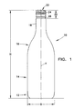
- Figure 1 is a side elevation view of a bottle.
- Figure 2 is a sectional outline of the exterior surface of the base of the bottle shown in Figure 1 taken through the axis of the bottle.
- a plastic bottle 10 is shown in Figure 1 to have a base 12, which will be detailed below.
- a sidewall 14 extends upward from the base 12.
- the diameter of the bottle 10 at the junction of the base 12 and sidewall 14 is given the dimension D.
- the sidewall 14 is shown to have a right cylindrical configuration, other configurations for the sidewall 14 are also contemplated.
- a shoulder 16 unitarily joins the top of the sidewall 14 to a neck 18.
- a finish portion 20 is provided at the top of the neck 18 to which a suitable closure, not shown, can be applied to seal an opening 22 that is present at the top of the bottle 10.
- the bottle 10 has an overall height H, and is generally symmetric about a vertical axis Y extending from the center of the base 12 to the center of the opening 22.
- the base 12 of the bottle 10 is shown in detail in Figure 2 to include a convex heel 24 extending downward from the sidewall 14.
- An upper portion 26 of the heel 24 is defined by an inside vertical radius R1, while a lower portion 28 of the heel 24 is defined by a smaller inside vertical radius R2.
- a continuous planar standing ring 30 joins the heel lower portion 28 to a central concavity 32 situated within the standing ring 30.
- the standing ring 30 has a horizontal surface of width W and an inner diameter S.
- the standing ring 30 lies in a horizontal plane X that is generally perpendicular to the longitudinal axis Y of the bottle 10.
- the central concavity 32 includes a first surface 34 having a lowermost portion 36.
- the first surface lowermost portion 36 is defined by a vertical inside radius R3 and smoothly joins the standing ring 30 to a portion 38, which can be conical.
- the conical portion 38 can extend upward from the lowermost portion 36 at an angle ⁇ with respect to the plane X.
- An upper margin of the conical portion 38 can be joined to a second surface 40 by a concave ring 42.
- the second surface 40 can be defined by a vertical inside radius R4 that can be centered on the vertical axis Y.
- the nadir 44 of the second surface 40 can be aligned with the vertical axis Y at a distance C above the plane X.
- the concave ring 42 can be defined by a vertical outside radius R5.
- Table I provides the various dimensions for both a comparative example bottle 1A that failed to perform satisfactorily and some working examples of bottles that did perform satisfactorily. All of the bottles reported in Table I were made from preforms having approximately 55 grams of plastic, including bottle 3.1A, which is designed to contain 1 liter of liquid while the remaining bottles of Table I are designed to contain only 750ml. It will be noted that certain of the dimensions overlap for both satisfactory bottles and un-satisfactory bottles while other dimensions identify a clear separation between success and failure under the top load test.
- the inside vertical radius R1 of the upper portion of the heel 26 in the failing bottle 1A has the same dimension as in two bottles that were successful. It will be further noted that the radius R1 can have a range of values that are successful. The radius R1 for satisfactory bottles can have a range of values from 1.42D down to 1.26D. When radius R1 is increased much beyond 1.42D, the base has a tendency to fold under itself under below-standard top loads. When the radius R1 is reduced much below 1.26D, some difficulty is observed in the complete formation of the heel.
- the inside vertical radius R4 of the second surface 40 in successful bottles can be larger, smaller or the same size as the failing bottle 1A.
- the radius R4 can have a range of values from 0.23D to 0.27D.
- the radius R4 may be able to assume values even outside this range.
- outside vertical radius R5 of the ring 42 joining the conical portion 38 to the second surface 40 in successful bottles can be larger, smaller or the same size as the failing bottle 1A.
- the radius R5 can have a range of values from 0.059D to 0.066D. The radius R5 may be able to assume values even outside this range.
- the width W of the standing ring 30 in the failing bottle 1A has the same dimension as in two bottles that were successful. It will be further noted that the width W can have a range of values that are successful. The width W for satisfactory bottles can have a range of values from 0.021D down to 0.016D. The width W may be able to assume values even outside this range.
- the height C of the nadir 44 of the second surface portion 40 above the standing ring 30 for successful bottles can be larger, smaller or the same size as the failing bottle 1A.
- the height C for satisfactory bottles can have a range of values from 0.159D down to 0.143D. The height C may be able to assume values even outside this range.
- radius R2 One dimension that clearly separates successfully performing bottles from unsuccessful bottles is the vertical inside radius R2 of the lowermost portion 28 of heel 24. Distinctly smaller radius values for radius R2 perform satisfactorily while larger radius values appear to contribute to failure.
- the radius R2 should have a value of less than 0.11D, and should preferably have a value between 0.039D and 0.067D.
- radius R3 Another dimension that separates successfully performing bottles from unsuccessful bottles is the vertical inside radius R3 of the lowermost portion 36 of the central concavity first surface 34. Distinctly smaller radius values for radius R3 perform satisfactorily while larger radius values also appear to contribute to failure.
- the radius R3 should have a value of less than 0.10D, and should preferably have a value between 0.055D and 0.084D.
- the diameter S of the standing ring 30 Another dimension that separates successfully performing bottles from unsuccessful bottles is the diameter S of the standing ring 30. Greater values for the diameter S are preferred over smaller values as they contribute to enhanced stability for the bottle.
- the diameter S can have a value of greater than 0.74D, and should preferably have a value between 0.75D and 0.82D. This greater diameter S can only be achieved through the adoption of the smaller values for R2 and R3 as discussed above.
Landscapes
- Engineering & Computer Science (AREA)
- Ceramic Engineering (AREA)
- Mechanical Engineering (AREA)
- Containers Having Bodies Formed In One Piece (AREA)
Description
- The present invention is directed to plastic bottles having a champagne style bottom structure closing the bottle lower end. The phrase champagne style is in reference to a base having an outside surface rotationally symmetric about a longitudinal axis of the bottle including a convex heel having an upper margin integrally formed with the lower end portion of the bottle sidewall, and a central concavity separated from the convex heel by a continuous standing ring that supports the bottle on any underlying surface.
- Bottle bases having a standard champagne dome have long been employed with glass bottles. Consumers have become accustomed to such base configurations, particularly when the bottles contain wine, whether a sparkling wine or a non-sparkling wine. In glass bottles, the champagne dome distributes forces exerted thereon by any internal pressure of the bottle. The standard champagne base also provides for a stable presentation of the bottle on a continuous standing ring. In glass bottles, the champagne base provides an adequate support during capping operations as well as during shipment. While the use of a champagne base is desirable from a consumer point of view, the application of such a base to plastic bottles has provided difficulties to the plastic bottle industry.
- Global trade in wine has increased rapidly in recent years and is currently estimated to exceed ten billion US dollars annually. Reports of health benefits and rising global incomes have spurred this increasing demand for wine. Together, the United States and the European Union accounted for over 60% of global imports of wine. The wine industry is considering the adoption of plastic bottles to lower both packaging and transportation costs. However the consumer still requires that the bottles have the base configuration to which they are accustomed. For reasons of efficiency and cost, the plastic bottle industry has embraced the conventional technique of blow molding plastic bottles from plastic preforms. The preforms are desirably made with the least amount of plastic that will still permit the finished bottle to satisfactorily perform in the intended manner. The industry often uses polyethylene terephthalate ("PET") or polypropylene ("PP") to construct plastic bottles due, in part, to the ability to reclaim and recycle such bottles. A barrier layer can be included to inhibit the migration of gases such as oxygen as well as moisture into or out of, the bottle. The barrier layer can be an intermediate extruded or injection formed layer made, for example, from ethylene vinyl alcohol ("EVOH"), or an interior layer such as a barely perceptible layer of glass, applied by plasma after the bottle is formed. In order to provide a plastic bottle constructed of PET or PP with desirable clarity characteristics, it is generally desirable to impart bi-axial stretching to the plastic material forming the bottle.
- A standard practice used to blow mold plastic bottles having a champagne base is to slightly increase the thickness of a majority of the base relative to the thickness of the remainder of the bottle. Preforms used to construct a bottle having such a base are known and do not require complex configurations. However, other attempts to blow mold an acceptable plastic bottle have placed material concentrations in specific predetermined areas of the base to increase the amount of stress that can be withstood without failing. One such prior art base configuration uses a stepped base to increase the thickness of the dome to a thickness that is substantially thicker than the dome of a standard base. Another prior art plastic bottle having a champagne base designed for enhanced pressure within the bottle includes a reinforced hoop to deter the champagne dome from inverting due to the enhanced internal pressure of the bottle. However, an intricate preform is required to direct material concentrations to the necessary areas of the base to form the reinforced hoop. This configuration increases material consumption and increases the difficulty of constructing the preforms. Because plastic bottles are desirably produced in extremely high volume, economies of scale make these configurations prohibitive.
US 2003/0116525 A1 discloses a molded plastic bottle designed to contain beer having a bottom structure that is within the champagne base family. That is, the bottom structure has an outside surface rotationally symmetric about a longitudinal axis of the bottle that includes a convex heel and a central concavity connected together by a standing ring. The standing ring is defined by an abrupt edge at the intersection between the lower margin of the convex heel and the central concavity. A lower margin of the convex heel defines an outer portion of the standing ring that supports the bottle on any underlying surface. The standing ring outer portion has a vertical inside radius of curvature of at least about 0.04 D, and preferably between about 0.045 D and 0.095 D. The central concavity includes at least a first surface having a lower most section defining an inner portion of the standing ring. The inner portion of the standing ring is inclined with respect to the plane containing the standing ring at an angle of between 20° and 60°. The angle of the inner surface defining the standing ring, coupled with the small initial outward radius of the outer surface defining the standing ring, permits sufficient polymer to be blown into the abrupt edge of the standing ring area to achieve the desired performance characteristics for the bottle without requiring that the parison have a thicken region related to this portion of the bottle. - There is therefore an unsatisfied need for a low-cost plastic bottle for containing wine having an acceptable appearance from the consumer point of view, which is stable on planar supporting surfaces and withstands the top load requirements experienced during the bottling and capping operation as well as during transport of the filled bottles.
- To solve this problem, a plastic bottle comprises the features of claim 1. Preferred embodiments of this bottle are defined in the subclaims.
- In one aspect, a plastic bottle has a sidewall and a bottom structure closing the bottle at a lower end portion of the sidewall, the bottom structure providing superior resistance to failure when the bottle is subjected to a vertical load. The bottom structure has an outside surface that is rotationally symmetric about a longitudinal axis of the bottle. The bottom outside surface includes a convex heel having an upper margin of diameter D integrally formed with the lower end portion of the sidewall. A lower margin of the convex heel leads to a continuous planar standing ring lying in a plane perpendicular to the longitudinal axis of the bottle that can support the bottle on any underlying surface. A central concavity is provided inside the standing ring. The central concavity includes a first surface defined by a circular cone inclined with respect to the plane of the standing ring, with the first surface having a lower most portion smoothly joining the standing ring. The inside vertical radius of curvature of the lower margin of the convex heel is less than 0,11 D and the lowermost portion of the inside concavity first surface has an inside vertical radius of between 0.055D and 0.084D to achieve the desired enhanced top load failure resistance.
- The lower margin of the convex heel leading to the planar standing ring can have an inside vertical radius of between 0.039D and 0.067D. A portion of the convex heel above the lower margin of the convex heel can have a vertical inside radius of curvature of between 1.26D and 1.42D.
- A portion of the inside concavity first surface above the lowermost portion of the first surface can be inclined at an angle of between 35° and 40° with respect to a plane formed by the standing ring.
- In preferred embodiments of the present invention, the central concavity can also include a second surface joined to an upper margin of the first surface by a concave ring. The second surface can be a downwardly convex dome centered on the longitudinal axis of the bottle. The inside concavity second surface can have a radius of curvature of between 0.23D and 0.27D. The inside concavity second surface can have a lowermost nadir situated between 0.14D and 0.16D above the standing ring. The concave ring joining the inside concavity first surface to the inside concavity second surface can have an outside vertical radius of between 0.059D and 0.066D.
- In further embodiments of the present invention the planar standing ring of the bottle can have a width of between 0.015D and 0.021D. The planar standing ring should have a diameter as large as possible to enhance bottle stability. With the preferred configurations the standing ring can have an inner diameter of between 0.73D and 0.82D. The planar character of the standing ring helps assure the bottle will remain upright on any underlying supporting surface.
- Each of these features contributes to a low gram weight bottle especially designed for containing wine having superior resistance to failure when subjected to a vertical force. For example, following these features one can form a one-liter bottle capable of withstanding a vertical force of 180 kg with only 54 grams of plastic. On the other hand a somewhat similar 750ml bottle made with the same amount of plastic and having features that differed in only small respects, detailed below in the comparative example, failed when subjected to a vertical force of less than 165 kg.
- Further, by adopting smaller values for the vertical inside radius for both the lowermost portion of the inside concavity first surface and the lower margin of the convex heel, one can achieve satisfactory performance with a greater standing ring diameter which contributes to enhanced bottle stability.
- Other features and advantages of the present invention will become apparent to those skilled in the art from the following disclosure of preferred embodiments of the present invention exemplifying the best mode of practicing the invention. The following disclosure references the accompanying drawings illustrating the preferred embodiments.
-
Figure 1 is a side elevation view of a bottle. -
Figure 2 is a sectional outline of the exterior surface of the base of the bottle shown inFigure 1 taken through the axis of the bottle. - A
plastic bottle 10 is shown inFigure 1 to have a base 12, which will be detailed below. Asidewall 14 extends upward from thebase 12. For the purpose of this disclosure, the diameter of thebottle 10 at the junction of thebase 12 andsidewall 14 is given the dimension D. While thesidewall 14 is shown to have a right cylindrical configuration, other configurations for thesidewall 14 are also contemplated. Ashoulder 16 unitarily joins the top of thesidewall 14 to aneck 18. Afinish portion 20 is provided at the top of theneck 18 to which a suitable closure, not shown, can be applied to seal anopening 22 that is present at the top of thebottle 10. While thefinish portion 20 is shown to include a threadedportion 24 and an optional tamper evidentring receiving portion 26, other configurations for thefinish portion 20 are also contemplated. Thebottle 10 has an overall height H, and is generally symmetric about a vertical axis Y extending from the center of the base 12 to the center of theopening 22. - The
base 12 of thebottle 10 is shown in detail inFigure 2 to include aconvex heel 24 extending downward from thesidewall 14. Anupper portion 26 of theheel 24 is defined by an inside vertical radius R1, while alower portion 28 of theheel 24 is defined by a smaller inside vertical radius R2. A continuous planar standingring 30 joins the heellower portion 28 to acentral concavity 32 situated within the standingring 30. The standingring 30 has a horizontal surface of width W and an inner diameter S. The standingring 30 lies in a horizontal plane X that is generally perpendicular to the longitudinal axis Y of thebottle 10. Thecentral concavity 32 includes afirst surface 34 having alowermost portion 36. The firstsurface lowermost portion 36 is defined by a vertical inside radius R3 and smoothly joins the standingring 30 to aportion 38, which can be conical. Theconical portion 38 can extend upward from thelowermost portion 36 at an angle β with respect to the plane X. An upper margin of theconical portion 38 can be joined to asecond surface 40 by aconcave ring 42. Thesecond surface 40 can be defined by a vertical inside radius R4 that can be centered on the vertical axis Y. Thenadir 44 of thesecond surface 40 can be aligned with the vertical axis Y at a distance C above the plane X. Theconcave ring 42 can be defined by a vertical outside radius R5. - However, every
bottle 10 having the general configuration shown inFigures 1 and2 will not have the top load strength deemed minimally satisfactory. Table I provides the various dimensions for both a comparative example bottle 1A that failed to perform satisfactorily and some working examples of bottles that did perform satisfactorily. All of the bottles reported in Table I were made from preforms having approximately 55 grams of plastic, including bottle 3.1A, which is designed to contain 1 liter of liquid while the remaining bottles of Table I are designed to contain only 750ml. It will be noted that certain of the dimensions overlap for both satisfactory bottles and un-satisfactory bottles while other dimensions identify a clear separation between success and failure under the top load test. - For example, it will be noted that the inside vertical radius R1 of the upper portion of the
heel 26 in the failing bottle 1A has the same dimension as in two bottles that were successful. It will be further noted that the radius R1 can have a range of values that are successful. The radius R1 for satisfactory bottles can have a range of values from 1.42D down to 1.26D. When radius R1 is increased much beyond 1.42D, the base has a tendency to fold under itself under below-standard top loads. When the radius R1 is reduced much below 1.26D, some difficulty is observed in the complete formation of the heel. - It will also be noted that the inside vertical radius R4 of the
second surface 40 in successful bottles can be larger, smaller or the same size as the failing bottle 1A. The radius R4 can have a range of values from 0.23D to 0.27D. The radius R4 may be able to assume values even outside this range. - It will also be noted that the outside vertical radius R5 of the
ring 42 joining theconical portion 38 to thesecond surface 40 in successful bottles can be larger, smaller or the same size as the failing bottle 1A. The radius R5 can have a range of values from 0.059D to 0.066D. The radius R5 may be able to assume values even outside this range. - It will be further noted that the width W of the standing
ring 30 in the failing bottle 1A has the same dimension as in two bottles that were successful. It will be further noted that the width W can have a range of values that are successful. The width W for satisfactory bottles can have a range of values from 0.021D down to 0.016D. The width W may be able to assume values even outside this range. - It will be further noted that the height C of the
nadir 44 of thesecond surface portion 40 above the standingring 30 for successful bottles can be larger, smaller or the same size as the failing bottle 1A. The height C for satisfactory bottles can have a range of values from 0.159D down to 0.143D. The height C may be able to assume values even outside this range. - One dimension that clearly separates successfully performing bottles from unsuccessful bottles is the vertical inside radius R2 of the
lowermost portion 28 ofheel 24. Distinctly smaller radius values for radius R2 perform satisfactorily while larger radius values appear to contribute to failure. The radius R2 should have a value of less than 0.11D, and should preferably have a value between 0.039D and 0.067D. - Another dimension that separates successfully performing bottles from unsuccessful bottles is the vertical inside radius R3 of the
lowermost portion 36 of the central concavityfirst surface 34. Distinctly smaller radius values for radius R3 perform satisfactorily while larger radius values also appear to contribute to failure. The radius R3 should have a value of less than 0.10D, and should preferably have a value between 0.055D and 0.084D. - Another dimension that separates successfully performing bottles from unsuccessful bottles is the diameter S of the standing
ring 30. Greater values for the diameter S are preferred over smaller values as they contribute to enhanced stability for the bottle. The diameter S can have a value of greater than 0.74D, and should preferably have a value between 0.75D and 0.82D. This greater diameter S can only be achieved through the adoption of the smaller values for R2 and R3 as discussed above. - From the forgoing description of the structure and operation of a preferred embodiment of the present invention, it will be apparent to those skilled in the art that the present invention is susceptible to numerous modifications and embodiments within the ability of those skilled in the art and without exercise of the inventive facility. Accordingly, the scope of the present invention is defined as set forth of the following claims.
Table I Examples R1 R2 R3 R4 R5 W S C β 1A (comp. ) 1.42D 0.111D 0.104D 0.250D 0.063D 0.021D 0.733D 0.150 D 40 ° 1AA 1.42D 0.067D 0.083D 0.250D 0.063D 0.021D 0.758D 0.150D 35 ° 2AA 1.42D 0.067D 0.083D 0.250D 0.063D 0.021D 0.758D 0.150D 35 ° 3.1A 1.27D 0.040D 0.056D 0.238D 0.060D 0.016D 0.818D 0.143D 35 ° 5A 1.37D 0.043D 0.060D 0.257D 0.064D 0.017D 0.803D 0.154D 35 ° 6A 1.41D 0.044D 0.062D 0.265D 0.066D 0.018D 0.797D 0.159D 35 °
Claims (10)
- A plastic bottle (10) having a sidewall (14) and a bottom structure (12) closing the bottle at a lower end portion of the sidewall and providing superior resistance to failure when the bottle (10) is subjected to a vertical load, the bottom (12) having an outside surface rotationally symmetric about a longitudinal axis (Y) of the bottle, the bottom outside surface including a convex heel (24) having an upper margin (26) of diameter D integrally formed with the lower end portion of the sidewall, a lower margin of the convex heel leading to a continuous planar standing ring (30) lying in a plane (X) perpendicular to the longitudinal axis (Y) of the bottle to support the bottle on any underlying surface, and a central concavity (32) inside the standing ring, the central concavity including a first surface (34) defined by a circular cone (38) inclined with respect to the plane (X) of the standing ring, the first surface having a lower most portion (36) smoothly joining the standing ring, the lower margin (28) of the convex heel (24) having an inside vertical radius (R2) of less than 0.11D, and characterized by the lowermost portion (36) of the first surface (34) having an inside vertical radius (R3) of between 0.055D and 0.084D to achieve enhance failure resistance and stability.
- The plastic bottle (10) of claim 1, further characterized by a portion (26) of the convex heel (24) above the lower margin (28) of the convex heel has a vertical inside radius (R1) of curvature of between 1.42D and 1.26D.
- The plastic bottle (10) of claim 1 or 2, further characterized by the planar standing ring (30) having a width (W) of between 0.015D and 0.021D.
- The plastic bottle (10) of any of claims 1 - 3, further characterized by the planar standing ring (30) having an inner diameter (S) of between 0.82D and 0.73D.
- The plastic bottle (10) of any of claims 1 - 4, further characterized by a portion (38) of the inside concavity first surface (34) above the lowermost portion of the first surface being inclined at an angle (β) of between 35° and 40° with respect to a plane (X) formed by the standing ring.
- The plastic bottle (10) of any of claims 1 - 5, further characterized by the lower margin (28) of the convex heel (24) leading to the planar standing ring (30) having an inside vertical radius (R2) of between 0.039D and 0.067D.
- The plastic bottle (10) of any of claims 1 - 6, further characterized by the central concavity (32) having a second surface (40) joined to an upper margin of the first surface (38) by a concave ring (42), the second surface being a downwardly convex dome centered on the longitudinal axis (Y) of the bottle.
- The plastic bottle (10) of claim 7, further characterized by the inside concavity second surface (40) having a radius of curvature (R4) of between 0.23D and 0.27D.
- The plastic bottle (10) of claim 7 or 8, further characterized by the inside concavity second surface (40) having a lowermost nadir (44) situated between 0.15D and 0.19D above the plane (X) of the standing ring (30).
- The plastic bottle (10) of any of claims 7 - 9, further characterized by the concave ring (42) joining the inside concavity first surface (34) to the inside concavity second surface (40) having an outside vertical radius (R5) of between 0.059D and 0.066D.
Applications Claiming Priority (1)
| Application Number | Priority Date | Filing Date | Title |
|---|---|---|---|
| US12/173,910 US20100012617A1 (en) | 2008-07-16 | 2008-07-16 | Plastic bottle with superior top load strength |
Publications (2)
| Publication Number | Publication Date |
|---|---|
| EP2145827A1 EP2145827A1 (en) | 2010-01-20 |
| EP2145827B1 true EP2145827B1 (en) | 2011-08-10 |
Family
ID=41100846
Family Applications (1)
| Application Number | Title | Priority Date | Filing Date |
|---|---|---|---|
| EP09075042A Not-in-force EP2145827B1 (en) | 2008-07-16 | 2009-01-23 | Plastic bottle with superior top load strength |
Country Status (6)
| Country | Link |
|---|---|
| US (1) | US20100012617A1 (en) |
| EP (1) | EP2145827B1 (en) |
| AU (1) | AU2008264203A1 (en) |
| CA (1) | CA2648163A1 (en) |
| MX (1) | MX2009003453A (en) |
| NZ (1) | NZ574816A (en) |
Families Citing this family (16)
| Publication number | Priority date | Publication date | Assignee | Title |
|---|---|---|---|---|
| US8668100B2 (en) | 2010-06-30 | 2014-03-11 | S.C. Johnson & Son, Inc. | Bottles with top loading resistance |
| US8851311B2 (en) | 2010-12-06 | 2014-10-07 | S.C. Johnson & Son, Inc. | Bottle with top loading resistance |
| USD660714S1 (en) | 2010-12-06 | 2012-05-29 | S.C. Johnson & Son, Inc. | Bottle |
| US8662329B2 (en) | 2010-12-06 | 2014-03-04 | S.C. Johnson & Son, Inc. | Bottle with top loading resistance with front and back ribs |
| MX361593B (en) * | 2012-06-05 | 2018-12-10 | Sa Des Eaux Minerales Devian | Blow moulded bottle, method of manufacturing and mould. |
| FR2998306B1 (en) * | 2012-11-22 | 2015-02-06 | Yann Franquet | PROCESS FOR BONIFYING A BEVERAGE OBTAINED BY ALCOHOLIC FERMENTATION SUCH AS WINE AND BOTTLE FOR CARRYING OUT SAID METHOD |
| CN104859912A (en) * | 2015-05-31 | 2015-08-26 | 南京绿庭农业科技有限公司 | Wine bottle having multicolor changing function |
| USD798711S1 (en) | 2016-02-18 | 2017-10-03 | Franke Technology And Trademark Ltd. | Pour top for beverage container |
| US9896248B2 (en) | 2016-02-18 | 2018-02-20 | Franke Technology And Trademark Ltd. | Bar bottle |
| USD797560S1 (en) * | 2016-02-18 | 2017-09-19 | Franke Technology And Trademark Ltd. | Bar bottle |
| JP2018108825A (en) * | 2016-12-28 | 2018-07-12 | サントリーホールディングス株式会社 | Resin container |
| AU2021202920A1 (en) * | 2020-05-08 | 2021-11-25 | Orora Packaging Australia Pty Ltd | A bottle, and an insert and a mould for making the bottle |
| US11972680B2 (en) * | 2020-06-12 | 2024-04-30 | Gojo Industries, Inc. | Base for table top sanitizer dispensing bottles and dispenser bottles |
| US10894625B1 (en) | 2020-07-29 | 2021-01-19 | Verre Vert, Inc. | Lightweight polymer bottle for wine and spirits |
| US12054304B2 (en) | 2022-06-03 | 2024-08-06 | Abbott Laboratories | Reclosable plastic bottle with waist and strengthening rib(s) |
| US12012253B1 (en) * | 2023-03-02 | 2024-06-18 | Verre Vert, Inc. | Lightweight polymer wine bottle suitable for use with natural cork or synthetic stoppers |
Family Cites Families (45)
| Publication number | Priority date | Publication date | Assignee | Title |
|---|---|---|---|---|
| DE1607895B2 (en) * | 1967-07-20 | 1977-02-10 | 4P Nicolaus Kempten Gmbh, 8960 Kempten | PRESSURE RESISTANT PLASTIC BOTTLE |
| US3720339A (en) * | 1970-09-24 | 1973-03-13 | Monsanto Co | Plastic container for pressurized materials-a |
| FR2132543B1 (en) * | 1971-04-08 | 1974-10-31 | Saint Gobain Pont A Mousson | |
| US3812996A (en) * | 1972-06-08 | 1974-05-28 | Carling O Keefe Ltd | Bottle carrying case |
| US3881621A (en) * | 1973-07-02 | 1975-05-06 | Continental Can Co | Plastic container with noneverting bottom |
| US4036926A (en) * | 1975-06-16 | 1977-07-19 | Owens-Illinois, Inc. | Method for blow molding a container having a concave bottom |
| USD249636S (en) * | 1976-12-06 | 1978-09-26 | Saml. Smith Old Brewery (Tadcaster) Limited | Bottle |
| FR2382373A1 (en) * | 1977-03-02 | 1978-09-29 | Solvay | HOLLOW BODY IN THERMOPLASTIC MATERIAL |
| US4108324A (en) * | 1977-05-23 | 1978-08-22 | The Continental Group, Inc. | Ribbed bottom structure for plastic container |
| FR2408524A1 (en) * | 1977-11-10 | 1979-06-08 | Solvay | HOLLOW BODY IN ORIENTED THERMOPLASTIC MATERIAL |
| FR2448480A1 (en) * | 1979-02-07 | 1980-09-05 | Solvay | HOLLOW BODY IN ORIENTED THERMOPLASTIC MATERIAL |
| US4525401A (en) * | 1979-11-30 | 1985-06-25 | The Continental Group, Inc. | Plastic container with internal rib reinforced bottom |
| US4342398A (en) * | 1980-10-16 | 1982-08-03 | Owens-Illinois, Inc. | Self-supporting plastic container for liquids |
| US4465199A (en) * | 1981-06-22 | 1984-08-14 | Katashi Aoki | Pressure resisting plastic bottle |
| US4403706A (en) * | 1982-06-08 | 1983-09-13 | The Continental Group, Inc. | Plastic container with hollow internal rib reinforced bottom and method of forming the same |
| USD282051S (en) * | 1983-03-18 | 1986-01-07 | Eldridge, Pope & Co. plc | Bottle |
| USD287936S (en) * | 1984-06-21 | 1987-01-27 | United Glass Limited | Bottle |
| USD290686S (en) * | 1984-08-29 | 1987-07-07 | Samuel Smith Old Brewery | Bottle |
| US4755404A (en) * | 1986-05-30 | 1988-07-05 | Continental Pet Technologies, Inc. | Refillable polyester beverage bottle and preform for forming same |
| USD287933S (en) * | 1986-10-10 | 1987-01-27 | United Glass Limited | Bottle |
| US4780257A (en) * | 1987-05-29 | 1988-10-25 | Devtech, Inc. | One piece self-standing blow molded plastic bottles |
| US4889752A (en) * | 1987-05-29 | 1989-12-26 | Devtech, Inc. | One piece self-standing blow molded plastic containers |
| USD326811S (en) * | 1988-08-11 | 1992-06-09 | Georg Messer | Bottle |
| USD330327S (en) * | 1988-11-01 | 1992-10-20 | Georg Messer | Bottle |
| US5038947A (en) * | 1989-08-24 | 1991-08-13 | Plasticon Patents, S.A. | Self-stabilizing base for pressurized bottle |
| US4989738A (en) * | 1989-10-13 | 1991-02-05 | General Electric Company | Plastic bottle with reinforced concave bottom |
| FR2717443B1 (en) * | 1994-03-16 | 1996-04-19 | Evian Eaux Min | Plastic molded bottle. |
| ES2104443T3 (en) * | 1995-04-27 | 1997-10-01 | Continental Pet De Gmbh | GEOMETRY OF THE REUSABLE PET CONTAINER FUND. |
| USD449531S1 (en) * | 1997-08-07 | 2001-10-23 | Podlaska Wytwornia Wodek “POLMOS” | Bottle |
| JP2000128140A (en) * | 1998-10-20 | 2000-05-09 | Aoki Technical Laboratory Inc | Polyester resin-made heat-resistant packaging container |
| USD434985S (en) * | 1999-04-16 | 2000-12-12 | Demptos Glass Company LLC | Bottle |
| JP2001029433A (en) * | 1999-07-15 | 2001-02-06 | Taisei Kako Co Ltd | Injection blow molded suckling bottle made of pes and its manufacture |
| CN2570208Y (en) * | 2001-09-03 | 2003-09-03 | 珠海中富聚酯啤酒瓶有限公司 | Polyester beer bottle |
| US6634517B2 (en) * | 2001-09-17 | 2003-10-21 | Crown Cork & Seal Technologies Corporation | Base for plastic container |
| USD470057S1 (en) * | 2001-11-14 | 2003-02-11 | V&S Vin & Spirit Aktiebolag | Bottle |
| US6769561B2 (en) * | 2001-12-21 | 2004-08-03 | Ball Corporation | Plastic bottle with champagne base |
| JP4080212B2 (en) * | 2002-01-31 | 2008-04-23 | 株式会社吉野工業所 | Thin-walled bottle made of synthetic resin |
| US20040000533A1 (en) * | 2002-07-01 | 2004-01-01 | Satya Kamineni | Pressurizable container |
| USD491809S1 (en) * | 2003-01-20 | 2004-06-22 | Amcor Limited | Container |
| US7370775B2 (en) * | 2003-12-22 | 2008-05-13 | Graham Packaging Company, L.P. | Pressure base for plastic container |
| US7287658B1 (en) * | 2004-01-08 | 2007-10-30 | Berry Plastics Corporation | Container having a base with a convex dome and method of use |
| US7416089B2 (en) * | 2004-12-06 | 2008-08-26 | Constar International Inc. | Hot-fill type plastic container with reinforced heel |
| US20060131257A1 (en) * | 2004-12-20 | 2006-06-22 | Ball Corporation | Plastic container with champagne style base |
| USD531048S1 (en) * | 2005-01-31 | 2006-10-31 | Krause Kurt W | Red wine bottle |
| USD546183S1 (en) * | 2005-08-12 | 2007-07-10 | Ball Corporation | Bottle |
-
2008
- 2008-07-16 US US12/173,910 patent/US20100012617A1/en not_active Abandoned
- 2008-12-24 AU AU2008264203A patent/AU2008264203A1/en not_active Abandoned
- 2008-12-29 CA CA002648163A patent/CA2648163A1/en not_active Abandoned
-
2009
- 2009-01-23 EP EP09075042A patent/EP2145827B1/en not_active Not-in-force
- 2009-02-11 NZ NZ574816A patent/NZ574816A/en not_active IP Right Cessation
- 2009-03-31 MX MX2009003453A patent/MX2009003453A/en active IP Right Grant
Also Published As
| Publication number | Publication date |
|---|---|
| MX2009003453A (en) | 2010-03-01 |
| AU2008264203A1 (en) | 2010-02-04 |
| NZ574816A (en) | 2010-03-26 |
| US20100012617A1 (en) | 2010-01-21 |
| EP2145827A1 (en) | 2010-01-20 |
| CA2648163A1 (en) | 2010-01-16 |
Similar Documents
| Publication | Publication Date | Title |
|---|---|---|
| EP2145827A1 (en) | Plastic bottle with superior top load strength | |
| US11220368B2 (en) | Swirl bell bottle with wavy ribs | |
| US6176382B1 (en) | Plastic container having base with annular wall and method of making the same | |
| US12195225B2 (en) | Swirl bell bottle with wavy ribs | |
| US7604140B2 (en) | Multi-sided spiraled plastic container | |
| US7882971B2 (en) | Rectangular container with vacuum panels | |
| US8567622B2 (en) | Dome shaped hot-fill container | |
| US20050279728A1 (en) | Container with structural ribs | |
| US20120181246A1 (en) | Panelless hot-fill plastic bottle | |
| US5024339A (en) | Plastics bottle | |
| AU2003266624B2 (en) | Synthetic resin bottle with grip | |
| CN102470950B (en) | Plastic bottle | |
| AU2022252702A1 (en) | Swirl bell bottle with wavy ribs | |
| US20010001200A1 (en) | Blow molded plastic container and method of making | |
| JP2015160650A (en) | Plastic bottle | |
| AU2021377690A9 (en) | Swirl bell bottle with wavy ribs |
Legal Events
| Date | Code | Title | Description |
|---|---|---|---|
| PUAI | Public reference made under article 153(3) epc to a published international application that has entered the european phase |
Free format text: ORIGINAL CODE: 0009012 |
|
| AK | Designated contracting states |
Kind code of ref document: A1 Designated state(s): AT BE BG CH CY CZ DE DK EE ES FI FR GB GR HR HU IE IS IT LI LT LU LV MC MK MT NL NO PL PT RO SE SI SK TR |
|
| AX | Request for extension of the european patent |
Extension state: AL BA RS |
|
| 17P | Request for examination filed |
Effective date: 20100719 |
|
| AKX | Designation fees paid |
Designated state(s): DE ES FR GB IT |
|
| GRAP | Despatch of communication of intention to grant a patent |
Free format text: ORIGINAL CODE: EPIDOSNIGR1 |
|
| RIC1 | Information provided on ipc code assigned before grant |
Ipc: B65D 1/02 20060101AFI20101126BHEP |
|
| GRAS | Grant fee paid |
Free format text: ORIGINAL CODE: EPIDOSNIGR3 |
|
| GRAA | (expected) grant |
Free format text: ORIGINAL CODE: 0009210 |
|
| AK | Designated contracting states |
Kind code of ref document: B1 Designated state(s): DE ES FR GB IT |
|
| REG | Reference to a national code |
Ref country code: GB Ref legal event code: FG4D |
|
| REG | Reference to a national code |
Ref country code: DE Ref legal event code: R096 Ref document number: 602009002037 Country of ref document: DE Effective date: 20111006 |
|
| PG25 | Lapsed in a contracting state [announced via postgrant information from national office to epo] |
Ref country code: IT Free format text: LAPSE BECAUSE OF FAILURE TO SUBMIT A TRANSLATION OF THE DESCRIPTION OR TO PAY THE FEE WITHIN THE PRESCRIBED TIME-LIMIT Effective date: 20110810 |
|
| PLBE | No opposition filed within time limit |
Free format text: ORIGINAL CODE: 0009261 |
|
| STAA | Information on the status of an ep patent application or granted ep patent |
Free format text: STATUS: NO OPPOSITION FILED WITHIN TIME LIMIT |
|
| 26N | No opposition filed |
Effective date: 20120511 |
|
| REG | Reference to a national code |
Ref country code: DE Ref legal event code: R097 Ref document number: 602009002037 Country of ref document: DE Effective date: 20120511 |
|
| REG | Reference to a national code |
Ref country code: FR Ref legal event code: ST Effective date: 20120928 |
|
| PG25 | Lapsed in a contracting state [announced via postgrant information from national office to epo] |
Ref country code: DE Free format text: LAPSE BECAUSE OF NON-PAYMENT OF DUE FEES Effective date: 20120801 |
|
| REG | Reference to a national code |
Ref country code: DE Ref legal event code: R119 Ref document number: 602009002037 Country of ref document: DE Effective date: 20120801 |
|
| PG25 | Lapsed in a contracting state [announced via postgrant information from national office to epo] |
Ref country code: FR Free format text: LAPSE BECAUSE OF NON-PAYMENT OF DUE FEES Effective date: 20120131 |
|
| PG25 | Lapsed in a contracting state [announced via postgrant information from national office to epo] |
Ref country code: ES Free format text: LAPSE BECAUSE OF FAILURE TO SUBMIT A TRANSLATION OF THE DESCRIPTION OR TO PAY THE FEE WITHIN THE PRESCRIBED TIME-LIMIT Effective date: 20111121 |
|
| GBPC | Gb: european patent ceased through non-payment of renewal fee |
Effective date: 20130123 |
|
| PG25 | Lapsed in a contracting state [announced via postgrant information from national office to epo] |
Ref country code: GB Free format text: LAPSE BECAUSE OF NON-PAYMENT OF DUE FEES Effective date: 20130123 |