EP2145671A1 - Device and method for regenerating exhaust purification catalyst - Google Patents
Device and method for regenerating exhaust purification catalyst Download PDFInfo
- Publication number
- EP2145671A1 EP2145671A1 EP08752519A EP08752519A EP2145671A1 EP 2145671 A1 EP2145671 A1 EP 2145671A1 EP 08752519 A EP08752519 A EP 08752519A EP 08752519 A EP08752519 A EP 08752519A EP 2145671 A1 EP2145671 A1 EP 2145671A1
- Authority
- EP
- European Patent Office
- Prior art keywords
- catalyst
- exhaust gas
- purifying exhaust
- gas
- oxidizing
- Prior art date
- Legal status (The legal status is an assumption and is not a legal conclusion. Google has not performed a legal analysis and makes no representation as to the accuracy of the status listed.)
- Withdrawn
Links
Images



Classifications
-
- B—PERFORMING OPERATIONS; TRANSPORTING
- B01—PHYSICAL OR CHEMICAL PROCESSES OR APPARATUS IN GENERAL
- B01J—CHEMICAL OR PHYSICAL PROCESSES, e.g. CATALYSIS OR COLLOID CHEMISTRY; THEIR RELEVANT APPARATUS
- B01J38/00—Regeneration or reactivation of catalysts, in general
- B01J38/04—Gas or vapour treating; Treating by using liquids vaporisable upon contacting spent catalyst
- B01J38/12—Treating with free oxygen-containing gas
-
- B—PERFORMING OPERATIONS; TRANSPORTING
- B01—PHYSICAL OR CHEMICAL PROCESSES OR APPARATUS IN GENERAL
- B01D—SEPARATION
- B01D53/00—Separation of gases or vapours; Recovering vapours of volatile solvents from gases; Chemical or biological purification of waste gases, e.g. engine exhaust gases, smoke, fumes, flue gases, aerosols
- B01D53/34—Chemical or biological purification of waste gases
- B01D53/74—General processes for purification of waste gases; Apparatus or devices specially adapted therefor
- B01D53/86—Catalytic processes
-
- B—PERFORMING OPERATIONS; TRANSPORTING
- B01—PHYSICAL OR CHEMICAL PROCESSES OR APPARATUS IN GENERAL
- B01D—SEPARATION
- B01D53/00—Separation of gases or vapours; Recovering vapours of volatile solvents from gases; Chemical or biological purification of waste gases, e.g. engine exhaust gases, smoke, fumes, flue gases, aerosols
- B01D53/34—Chemical or biological purification of waste gases
- B01D53/92—Chemical or biological purification of waste gases of engine exhaust gases
- B01D53/94—Chemical or biological purification of waste gases of engine exhaust gases by catalytic processes
- B01D53/9445—Simultaneously removing carbon monoxide, hydrocarbons or nitrogen oxides making use of three-way catalysts [TWC] or four-way-catalysts [FWC]
-
- B—PERFORMING OPERATIONS; TRANSPORTING
- B01—PHYSICAL OR CHEMICAL PROCESSES OR APPARATUS IN GENERAL
- B01J—CHEMICAL OR PHYSICAL PROCESSES, e.g. CATALYSIS OR COLLOID CHEMISTRY; THEIR RELEVANT APPARATUS
- B01J23/00—Catalysts comprising metals or metal oxides or hydroxides, not provided for in group B01J21/00
- B01J23/90—Regeneration or reactivation
- B01J23/96—Regeneration or reactivation of catalysts comprising metals, oxides or hydroxides of the noble metals
-
- B—PERFORMING OPERATIONS; TRANSPORTING
- B01—PHYSICAL OR CHEMICAL PROCESSES OR APPARATUS IN GENERAL
- B01J—CHEMICAL OR PHYSICAL PROCESSES, e.g. CATALYSIS OR COLLOID CHEMISTRY; THEIR RELEVANT APPARATUS
- B01J38/00—Regeneration or reactivation of catalysts, in general
- B01J38/04—Gas or vapour treating; Treating by using liquids vaporisable upon contacting spent catalyst
- B01J38/10—Gas or vapour treating; Treating by using liquids vaporisable upon contacting spent catalyst using elemental hydrogen
-
- F—MECHANICAL ENGINEERING; LIGHTING; HEATING; WEAPONS; BLASTING
- F01—MACHINES OR ENGINES IN GENERAL; ENGINE PLANTS IN GENERAL; STEAM ENGINES
- F01N—GAS-FLOW SILENCERS OR EXHAUST APPARATUS FOR MACHINES OR ENGINES IN GENERAL; GAS-FLOW SILENCERS OR EXHAUST APPARATUS FOR INTERNAL-COMBUSTION ENGINES
- F01N3/00—Exhaust or silencing apparatus having means for purifying, rendering innocuous, or otherwise treating exhaust
- F01N3/08—Exhaust or silencing apparatus having means for purifying, rendering innocuous, or otherwise treating exhaust for rendering innocuous
- F01N3/10—Exhaust or silencing apparatus having means for purifying, rendering innocuous, or otherwise treating exhaust for rendering innocuous by thermal or catalytic conversion of noxious components of exhaust
- F01N3/18—Exhaust or silencing apparatus having means for purifying, rendering innocuous, or otherwise treating exhaust for rendering innocuous by thermal or catalytic conversion of noxious components of exhaust characterised by methods of operation; Control
- F01N3/20—Exhaust or silencing apparatus having means for purifying, rendering innocuous, or otherwise treating exhaust for rendering innocuous by thermal or catalytic conversion of noxious components of exhaust characterised by methods of operation; Control specially adapted for catalytic conversion
- F01N3/2006—Periodically heating or cooling catalytic reactors, e.g. at cold starting or overheating
- F01N3/2013—Periodically heating or cooling catalytic reactors, e.g. at cold starting or overheating using electric or magnetic heating means
-
- F—MECHANICAL ENGINEERING; LIGHTING; HEATING; WEAPONS; BLASTING
- F01—MACHINES OR ENGINES IN GENERAL; ENGINE PLANTS IN GENERAL; STEAM ENGINES
- F01N—GAS-FLOW SILENCERS OR EXHAUST APPARATUS FOR MACHINES OR ENGINES IN GENERAL; GAS-FLOW SILENCERS OR EXHAUST APPARATUS FOR INTERNAL-COMBUSTION ENGINES
- F01N3/00—Exhaust or silencing apparatus having means for purifying, rendering innocuous, or otherwise treating exhaust
- F01N3/08—Exhaust or silencing apparatus having means for purifying, rendering innocuous, or otherwise treating exhaust for rendering innocuous
- F01N3/10—Exhaust or silencing apparatus having means for purifying, rendering innocuous, or otherwise treating exhaust for rendering innocuous by thermal or catalytic conversion of noxious components of exhaust
- F01N3/18—Exhaust or silencing apparatus having means for purifying, rendering innocuous, or otherwise treating exhaust for rendering innocuous by thermal or catalytic conversion of noxious components of exhaust characterised by methods of operation; Control
- F01N3/20—Exhaust or silencing apparatus having means for purifying, rendering innocuous, or otherwise treating exhaust for rendering innocuous by thermal or catalytic conversion of noxious components of exhaust characterised by methods of operation; Control specially adapted for catalytic conversion
- F01N3/206—Adding periodically or continuously substances to exhaust gases for promoting purification, e.g. catalytic material in liquid form, NOx reducing agents
-
- F—MECHANICAL ENGINEERING; LIGHTING; HEATING; WEAPONS; BLASTING
- F01—MACHINES OR ENGINES IN GENERAL; ENGINE PLANTS IN GENERAL; STEAM ENGINES
- F01N—GAS-FLOW SILENCERS OR EXHAUST APPARATUS FOR MACHINES OR ENGINES IN GENERAL; GAS-FLOW SILENCERS OR EXHAUST APPARATUS FOR INTERNAL-COMBUSTION ENGINES
- F01N3/00—Exhaust or silencing apparatus having means for purifying, rendering innocuous, or otherwise treating exhaust
- F01N3/08—Exhaust or silencing apparatus having means for purifying, rendering innocuous, or otherwise treating exhaust for rendering innocuous
- F01N3/10—Exhaust or silencing apparatus having means for purifying, rendering innocuous, or otherwise treating exhaust for rendering innocuous by thermal or catalytic conversion of noxious components of exhaust
- F01N3/18—Exhaust or silencing apparatus having means for purifying, rendering innocuous, or otherwise treating exhaust for rendering innocuous by thermal or catalytic conversion of noxious components of exhaust characterised by methods of operation; Control
- F01N3/22—Control of additional air supply only, e.g. using by-passes or variable air pump drives
-
- B—PERFORMING OPERATIONS; TRANSPORTING
- B01—PHYSICAL OR CHEMICAL PROCESSES OR APPARATUS IN GENERAL
- B01D—SEPARATION
- B01D2255/00—Catalysts
- B01D2255/10—Noble metals or compounds thereof
- B01D2255/102—Platinum group metals
- B01D2255/1021—Platinum
-
- B—PERFORMING OPERATIONS; TRANSPORTING
- B01—PHYSICAL OR CHEMICAL PROCESSES OR APPARATUS IN GENERAL
- B01D—SEPARATION
- B01D2255/00—Catalysts
- B01D2255/20—Metals or compounds thereof
- B01D2255/206—Rare earth metals
-
- B—PERFORMING OPERATIONS; TRANSPORTING
- B01—PHYSICAL OR CHEMICAL PROCESSES OR APPARATUS IN GENERAL
- B01J—CHEMICAL OR PHYSICAL PROCESSES, e.g. CATALYSIS OR COLLOID CHEMISTRY; THEIR RELEVANT APPARATUS
- B01J23/00—Catalysts comprising metals or metal oxides or hydroxides, not provided for in group B01J21/00
- B01J23/38—Catalysts comprising metals or metal oxides or hydroxides, not provided for in group B01J21/00 of noble metals
- B01J23/40—Catalysts comprising metals or metal oxides or hydroxides, not provided for in group B01J21/00 of noble metals of the platinum group metals
- B01J23/42—Platinum
-
- B—PERFORMING OPERATIONS; TRANSPORTING
- B01—PHYSICAL OR CHEMICAL PROCESSES OR APPARATUS IN GENERAL
- B01J—CHEMICAL OR PHYSICAL PROCESSES, e.g. CATALYSIS OR COLLOID CHEMISTRY; THEIR RELEVANT APPARATUS
- B01J23/00—Catalysts comprising metals or metal oxides or hydroxides, not provided for in group B01J21/00
- B01J23/38—Catalysts comprising metals or metal oxides or hydroxides, not provided for in group B01J21/00 of noble metals
- B01J23/54—Catalysts comprising metals or metal oxides or hydroxides, not provided for in group B01J21/00 of noble metals combined with metals, oxides or hydroxides provided for in groups B01J23/02 - B01J23/36
- B01J23/56—Platinum group metals
- B01J23/63—Platinum group metals with rare earths or actinides
-
- F—MECHANICAL ENGINEERING; LIGHTING; HEATING; WEAPONS; BLASTING
- F01—MACHINES OR ENGINES IN GENERAL; ENGINE PLANTS IN GENERAL; STEAM ENGINES
- F01N—GAS-FLOW SILENCERS OR EXHAUST APPARATUS FOR MACHINES OR ENGINES IN GENERAL; GAS-FLOW SILENCERS OR EXHAUST APPARATUS FOR INTERNAL-COMBUSTION ENGINES
- F01N2240/00—Combination or association of two or more different exhaust treating devices, or of at least one such device with an auxiliary device, not covered by indexing codes F01N2230/00 or F01N2250/00, one of the devices being
- F01N2240/16—Combination or association of two or more different exhaust treating devices, or of at least one such device with an auxiliary device, not covered by indexing codes F01N2230/00 or F01N2250/00, one of the devices being an electric heater, i.e. a resistance heater
-
- F—MECHANICAL ENGINEERING; LIGHTING; HEATING; WEAPONS; BLASTING
- F01—MACHINES OR ENGINES IN GENERAL; ENGINE PLANTS IN GENERAL; STEAM ENGINES
- F01N—GAS-FLOW SILENCERS OR EXHAUST APPARATUS FOR MACHINES OR ENGINES IN GENERAL; GAS-FLOW SILENCERS OR EXHAUST APPARATUS FOR INTERNAL-COMBUSTION ENGINES
- F01N2240/00—Combination or association of two or more different exhaust treating devices, or of at least one such device with an auxiliary device, not covered by indexing codes F01N2230/00 or F01N2250/00, one of the devices being
- F01N2240/28—Combination or association of two or more different exhaust treating devices, or of at least one such device with an auxiliary device, not covered by indexing codes F01N2230/00 or F01N2250/00, one of the devices being a plasma reactor
-
- F—MECHANICAL ENGINEERING; LIGHTING; HEATING; WEAPONS; BLASTING
- F01—MACHINES OR ENGINES IN GENERAL; ENGINE PLANTS IN GENERAL; STEAM ENGINES
- F01N—GAS-FLOW SILENCERS OR EXHAUST APPARATUS FOR MACHINES OR ENGINES IN GENERAL; GAS-FLOW SILENCERS OR EXHAUST APPARATUS FOR INTERNAL-COMBUSTION ENGINES
- F01N2610/00—Adding substances to exhaust gases
- F01N2610/04—Adding substances to exhaust gases the substance being hydrogen
-
- Y—GENERAL TAGGING OF NEW TECHNOLOGICAL DEVELOPMENTS; GENERAL TAGGING OF CROSS-SECTIONAL TECHNOLOGIES SPANNING OVER SEVERAL SECTIONS OF THE IPC; TECHNICAL SUBJECTS COVERED BY FORMER USPC CROSS-REFERENCE ART COLLECTIONS [XRACs] AND DIGESTS
- Y02—TECHNOLOGIES OR APPLICATIONS FOR MITIGATION OR ADAPTATION AGAINST CLIMATE CHANGE
- Y02A—TECHNOLOGIES FOR ADAPTATION TO CLIMATE CHANGE
- Y02A50/00—TECHNOLOGIES FOR ADAPTATION TO CLIMATE CHANGE in human health protection, e.g. against extreme weather
- Y02A50/20—Air quality improvement or preservation, e.g. vehicle emission control or emission reduction by using catalytic converters
-
- Y—GENERAL TAGGING OF NEW TECHNOLOGICAL DEVELOPMENTS; GENERAL TAGGING OF CROSS-SECTIONAL TECHNOLOGIES SPANNING OVER SEVERAL SECTIONS OF THE IPC; TECHNICAL SUBJECTS COVERED BY FORMER USPC CROSS-REFERENCE ART COLLECTIONS [XRACs] AND DIGESTS
- Y02—TECHNOLOGIES OR APPLICATIONS FOR MITIGATION OR ADAPTATION AGAINST CLIMATE CHANGE
- Y02T—CLIMATE CHANGE MITIGATION TECHNOLOGIES RELATED TO TRANSPORTATION
- Y02T10/00—Road transport of goods or passengers
- Y02T10/10—Internal combustion engine [ICE] based vehicles
- Y02T10/12—Improving ICE efficiencies
Definitions
- the present invention relates to an apparatus and a method for regenerating a deteriorated catalyst for purifying exhaust gas.
- various catalysts for purifying exhaust gas such as oxidizing catalysts, three-way catalysts and NOx storage-reduction catalysts are loaded.
- these catalysts for purifying exhaust gas harmful components in the exhaust gas are purified.
- catalytic activity is developed by a noble metal, such as Pt (platinum), Rh (rhodium) or Pd (palladium).
- the noble metal is used under the loaded condition onto a support comprising a porous oxide, such as alumina.
- the particle of the noble metal In order to develop the maximum activity of the noble metal, it is preferable for the particle of the noble metal to be loaded under the high dispersion condition and as fine as possible. Therefore, the noble metals are loaded onto the support by an absorption loading method or an impregnate loading method using solution of soluble noble metal compounds, for example complex salt or nitrate. The noble metals loaded by these methods are loaded under high dispersion condition as fine particles having extreme small particle diameter. Thus, high catalytic activities can be developed.
- Japanese Unexamined Patent Application Publication No. 2002-282,710 discloses a method of regenerating a catalyst for steam reforming reaction by supplying fuel and air to the catalyst. According to this method, the catalysts are heated to 500 °C ⁇ 800 °C by the combustion of fuel. The catalysts are regenerated by reducing the noble metals under the heated condition.
- Japanese Unexamined Patent Application Publication No. 2001-058,121 discloses a regenerating apparatus and a regenerating method for regenerating a catalyst for decomposing dioxin or the like. According to this technology, a deteriorated catalyst can be regenerated by processing with ammonia type reducing agent. However, according to this technology, the use of catalyst has to be interrupted because the catalyst is taken out for regeneration. Moreover, the used catalysts are Ti-V system catalysts and noble metals are not used in No. 2001-058121 .
- Japanese Unexamined Patent Application Publication No. 2006-118,500 and Japanese Unexamined Patent Application Publication No. 2006-299,857 disclose a method for regenerating a catalyst in use.
- the former is a method for regenerating by reducing NOx storage-reduction catalysts with a hydrocarbon partial oxide and is not a method for regenerating purification activities of noble metals.
- the latter is a method for regenerating a diesel particulate filter. It is a method for regenerating a filter by removing deposited diesel particulates and is not a method for regenerating purification activities of noble metals.
- the present invention has been made in view of the aforementioned problems, and it is an assignment to be achieved to regenerate a deteriorated catalyst without interrupting the use of catalyst and also without deteriorating the drivability.
- a characteristic of the apparatus for regenerating a catalyst for purifying exhaust gas according to the present invention which solves the aforementioned problem lies in the apparatus comprising a heating means which heats the catalyst for purifying exhaust gas including a noble metal at the time of stopping fuel supply to a vehicle engine, an oxidizing gas supplying means which supplies an oxidizing gas to the catalyst for purifying exhaust gas heated by the heating means, a reducing gas supplying means which supplies a reducing gas to the catalyst for purifying exhaust gas heated by the heating means and a switching means which switches over from driving of the oxidizing gas supplying means to driving of the reducing gas supplying means and from driving of the reducing gas supplying means to driving of the oxidizing gas supplying means.
- an apparatus for regenerating a deteriorated catalyst for purifying exhaust gas comprising an oxidizing gas supplying means which supplies the oxidizing gas to the catalyst for purifying exhaust gas including a noble metal, a reducing gas supplying means which supplies a reducing gas to the catalyst for puri fying exhaust gas and a plasma generator which generates discharge plasma in the oxidizing gas or in the reducing gas existing between the oxidizing gas supplying means and the reducing gas supplying means and the catalyst for purifying exhaust gas, the oxidizing gas supplying means supplying an oxidizing gas turned into plasma to the catalyst for purifying exhaust gas and then the reducing gas supplying means supplying a reducing gas turned into plasma to the catalyst for purifying exhaust gas at the time of stopping fuel supply to a vehicle engine.
- a characteristic of a method for regenerating a catalyst for purifying exhaust gas according to the present invention lies in a method at the time of stopping fuel supply to a vehicle engine comprising the steps of heating the catalyst for purifying exhaust gas including a noble metal, oxidizing the noble metal by supplying an oxidizing gas to the heated catalyst for purifying exhaust gas and reducing the noble metal under oxidized condition by supplying a reducing gas to the heated catalyst for purifying exhaust gas.
- Another characteristic of a method for regenerating a catalyst for purifying exhaust gas according to the present invention lies in a method at the time of stopping fuel supply to a vehicle engine comprising the successive steps of oxidizing a noble metal by supplying an oxidizing gas activated by a discharge plasma to a catalyst for purifying exhaust gas including the noble metal and reducing the noble metal under oxidized condition by supplying a reducing gas activated by a discharge plasma to the catalyst for purifying exhaust gas.
- a catalyst for purifying exhaust gas is regenerated at the time of stopping fuel supply to a vehicle engine. For example, when the driver' s foot is released from the accelerator pedal during the high speed driving, the fuel supply to a vehicle engine is stopped by the fuel-cut control and the braking force is applied by the engine brake. If the catalyst for purifying exhaust gas is regenerated at that time, the regeneration can be carried out without affecting the drivability.
- the catalyst activity of the catalyst for purifying exhaust gas is reactivated by the regenerating process, it is not necessary to load the noble metal in larger quantity for anticipating the deterioration in advance. Therefore, the loading quantity of the noble metal can be reduced. According to this, the catalyst for purifying exhaust gas can be provided at a lower cost.
- the reducing step is carried out after the oxidizing step.
- the catalytic poisons for example hydrocarbon, which are absorbed on the noble metal are oxidized and removed.
- the particles of the noble metal become oxidized as pure oxide and the like.
- the particles of the noble metal are reduced and are re-dispersed on the support simultaneously and as a result, the particles of the noble metal become fine. Owing to this, the catalyst activity is reactivated.
- a catalyst for purifying exhaust gas can be regenerated in a short period of time with high efficiency of regeneration. Furthermore, if an oxidizing gas and a reducing gas are activated by discharge plasma and then these gases are supplied to a catalyst for purifying exhaust gas, regeneration at room temperature can be carried out. Therefore, a heating means is not needed and the cost can be further saved.
- An apparatus for regenerating according to the present invention comprises a heatingmeans, an oxidizing gas supplyingmeans, a reducing gas supplying means, and a switching means.
- the heating means can heat a catalyst for purifying exhaust gas at the time of stopping fuel supply to an engine, that is, the time when the catalyst is not heated by exhaust gas.
- As heating means it is possible to use an electric heater and the like.
- a catalyst for purifying exhaust gas with a heater attached may be used.
- a catalyst for purifying exhaust gas can be heated directly.
- an oxidizing gas and a reducing gas can be heated instead of heating a catalyst for purifying exhaust gas directly.
- the catalyst for purifying exhaust gas can be heated indirectly.
- the time of stopping fuel supply to an engine can be the time when vehicles stop or park, the fuel-cut time at driving with a high speed or the time when a hybrid car is driven only by the electric motor.
- the oxidizing gas supplying means is a means which supplies an oxidizing gas to the catalyst for purifying exhaust gas heated by the heating means.
- an oxidizing gas is a gas which can oxidize noble metals in the heated catalyst for purifying exhaust gas, and the gas including 2% or more oxygen, preferably the gas including 5% or more oxygen can be used. Air existing affluently on the earth can be used.
- the catalyst for purifying exhaust gas is preferably heated to 400 °C ⁇ 800 °C by the heating means.
- the temperature of the catalyst for purifying exhaust gas is below 400 °C, efficient energy to re-disperse by oxidizing the noble metals may not be obtained. As a result, it is difficult to re-disperse noble metals.
- the temperature is above 800 °C, because the heat energy is larger than reciprocal action between the support and the noble metals, granular growth of the noble metal is extraordinary. As a result, it is difficult to re-disperse even though the reducing step is carrying out.
- the catalyst for purifying exhaust gas is heated in a range of 550 °C ⁇ 800 °C.
- the reducing gas supplying means is a means which supplies a reducing gas to the catalyst for purifying exhaust gas heated by the heating means after supplying the oxidizing gas.
- a reducing gas is the gas which reduces oxidized noble metals to noble metals.
- Fuel such as gasoline, CO, HC, NH 3 , H 2 and the like can be exemplified as a reducing gas. Among these, CO, H 2 , light HC and NH 3 are more preferable.
- the catalyst for purifying exhaust gas is heated to 100 °C or above by the heating means.
- the temperature of the catalyst for purifying exhaust gas is below 100 °C, it is difficult to reduce oxidized noble metals to noble metals. Accordingly, regenerating the catalyst becomes difficult. It is more preferable to heat the catalyst to 300 °C or above.
- An electric pump, an injector and the like can be used for the oxidizing gas supplying means and the reducing gas supplying means.
- the oxidizing gas supplying means takes air in and supplies the air to the catalyst for purifying exhaust gas.
- the reducing gas supplying means supplies fuel, urea solution, hydrogen gas or ammonia gas from respective tank or cylinder to the catalyst for purifying exhaust gas.
- an oxidizing gas or a reducing gas to the catalyst for purifying exhaust gas utilizing the rotation of a vehicle wheel or the reverse-driving power when the engine is reverse-driven by rotation of the vehicle wheel at the time of stopping fuel supply. This may reduce the consumption of electric power, compared with using an electric pump.
- the process time in the oxidizing step differs depending on the oxygen level in the oxidizing gas and the heating temperature of the catalyst for purifying exhaust gas , but usually the process time in the oxidizing step is about tens of seconds in the case that an air is used as the oxidizing gas.
- the process time in the reducing step differs depending on the type of the reducing gas or the heating temperature of the catalyst for purifying exhaust gas. Therefore, it is preferable to carry out the reducing step for only the time needed for regeneration.
- Such desirable time for reducing step can be obtained in advance by researching the relation between the heating temperature of the catalyst for purifying exhaust gas and the reduced degree according to the type of the reducing gas to be used, by experiments.
- a plasma generator which generates discharge plasma in the oxidizing gas and the reducing gas existing between the oxidizing gas supplying means and the reducing gas supplying means, and the catalyst for purifying exhaust gas.
- the reactivity improves by the oxidizing gas and the reducing gas activated by the discharge plasma, and the noble metal can be oxidized even under the room temperature and also the noble metal under the oxidized condition can be reduced to the noble metal under the room temperature. Therefore, the heating means becomes unnecessary and the electric energy can be saved.
- the plasma generator is generally constituted to generate a discharge plasma according to the application of the high voltage of 5kV ⁇ 50kV.
- Corona discharge generator, barrier discharge generator, inductively coupled plasma generator, arc discharge generator and the like can be used for plasma generator.
- Direct-current voltage, alternating voltage, alternating pulse voltage and the like can be used for a high voltage generator.
- the shape of the electrode is not limited to any particular shape. However, it is preferable to have the shape which is easy to discharge such as for example fine line shape, needle shape, edge shape and the like. It is also preferable to cover the electrode with dielectric.
- ozone, OH radical, NO and the like can be used in addition to the gas including 2% or more oxygen, the gas including 5% or more oxygen, and air as an oxidizing gas.
- N radical, H radical and the like can be used in addition to fuel such as gasoline, CO, HC, NH 3 , H 2 and the like.
- Ozone, OH radical, NO, N radical and H radical may exist before discharge and may be generated after generating of discharge plasma.
- Oxidizing catalysts, three-way catalysts, NOx storage-reduction catalysts and the like can be used as the catalyst for purifying exhaust gas in the present invention.
- Alumina, titania, ceria, zirconia, ceria-zirconia solid solutions and the like are exemplified as the support. It is preferable to include at least ceria in the support.
- Pt, Rh, Pd, Ir (iridium) and the like are exemplified as noble metal loaded onto the support. It is preferable to include at least Pt as a noble metal. The reason is that in the case of Pt loaded onto the support including ceria, the effect of the present invention is remarkable.
- the loading quantity of the noble metal in the catalyst for purifying exhaust gas is not limited to any particular quantity. The general loading quantity can be used.
- the pellet catalyst described above was put into a cannulated furnace. Nitrogen durability test was carried out, in which the pellet catalysts are held under the nitrogen gas atmosphere for 5 hours at 950 °C and 1000 °C, respectively. The catalysts after the nitrogen durability test were subjected to the oxidizing step where the catalysts are held for 2 hours at 400 °C, 600 °C and 800 °C, respectively and then the respective oxidized catalysts were subjected to the reducing step where the oxidized catalysts are held for 15 minutes at 500 °C in nitrogen gas including 3 volume% H 2 .
- Example No. 1 The respective catalysts after nitrogen durability test carried out in the same manner as Example No. 1 were not subjected to the oxidizing step. And then the reducing step was only carried out for the respective catalysts in the same manner as Example No. 1.
- the pellet catalyst described above was put into a cannulated furnace.
- RL durability test was carried out, in which the pellet catalysts are held under the atmosphere which is repeating rich gas atmosphere (CO:2%,N 2 :balance) and lean gas atmosphere (O 2 :5%,N 2 :balance) for each 120 seconds alternately, for 5 hours at 1000 °C.
- the oxidizing step were carried out the catalysts after RL durability test, where the catalysts are held for 2 hours at 600 °C in air and then the reducing step were carried out the oxidized catalysts, where the oxidized catalysts are held for 15 minutes at 500 °C in nitrogen gas including 3 volume% H 2 .
- Example No. 2 The catalysts after RL durability test carried out in the same manner as Example No. 2 were not subjected to the oxidizing step. And then the reducing step was only carried out the catalysts in the same manner as Example No. 2.
- the pellet catalyst described above was put into an electric furnace. Air durability test was carried out, in which the pellet catalysts are held under the air for 5 hours at 1000 °C. The catalysts after air durability test were subjected to the oxidizing step where the catalysts are held for 2 hours at 600 °C in air and then the oxidized catalysts were subjected to the reducing step where the oxidized catalysts are held for 15 minutes at 500 °C in nitrogen gas including 3 volume% H 2 .
- Example No. 3 The catalysts after air durability test carried out in the same manner as Example No. 3 were not subjected to the oxidizing step. And then the reducing step was only carried out the catalysts in the same manner as Example No. 3.
- the activity of purification of the catalyst according to Example No. 2 was superior compared with the catalyst according to Comparative Example No. 2 and the activity of purification of the catalyst according to Example No. 3 was superior compared with the catalyst according to Comparative Example No.3. That is, even if the conditions of the durability test are different, it is apparent that the catalyst deteriorated at the durability test was regenerated by carrying out the oxidizing step and the reducing step.
- Example No.3 air durability test in which catalysts are held under the air for 5 hours at 1000 °C was similar to that in Comparative Example No.3.
- the difference between Comparative Example No.3 and Example No. 3 is whether the oxidizing step (the catalysts are held under the air for 2 hours at 600 °C) was carried out or not.
- the oxidizing step is preferably carried out below 1000 °C.
- a honeycomb substrate which was made of cordierite (cell density : 600 cpsi, wall thickness : 75 ⁇ m, diameter : 103mm, length : 105 mm, 0.875 L), was prepared.
- the slurry which includes 120 parts by mass of Pt/CeO 2 -ZrO 2 catalyst powder similar to that obtained at the preparation of the pellet catalyst, and 10 parts by mass of a ceria sol binder, was wash-coated onto the honeycomb substrate and then the honeycomb catalyst was prepared.
- 120 g of Pt / CeO 2 - ZrO 2 catalyst powder per 1 L of honeycomb catalyst was included and 0.6 g of Pt was loaded per 1 L of honeycomb catalyst.
- the first honeycomb catalyst described above was fit onto an exhaust system of a 4.3-L gasoline engine.
- the actual durability test was conducted for 50 hours under a condition that the catalyst-bed temperature is 750 °C and 3-second fuel cut control and 7-second feed back control are repeated alternately.
- the fuel cut control is the control in which fuel supply to the engine is cut under the condition that the vehicle wheel is rotating. During the fuel cut control, only the air is exhausted from the engine and no exhaust gas is exhausted from the engine. Moreover, the feed back control controls the air-fuel ratio within a predetermined range by controlling a fuel supply amount through detection of oxygen level in the exhaust gas.
- the exhaust gas atmosphere in this case changes a few to rich atmosphere or lean atmosphere referencing stoichiometry atmosphere.
- the catalysts after the actual durability test described above were subjected to the oxidizing step for holding for 2 hours at 800 °C in the air, and then the oxidized catalysts were subjected to the reducing step for holding for 1 hour at 700°C in nitrogen gas including 3 volume% CO.
- the first honeycomb catalyst described above was fit onto an exhaust system of a engine similar to that in Example No. 4 and the actual durability test was carried out in the manner similar to that in Example No. 4. The oxidizing step and the reducing step were not carried out.
- a honeycomb substrate which was made of cordierite (cell density : 600 cpsi, wall thickness : 75 ⁇ m, diameter : 103 mm, length : 105 mm, 0.875 L), was prepared.
- the slurry which includes 120 parts by mass of Pt-Ba/CeO 2 -ZrO 2 catalyst powder and 10 parts by mass of a ceria sol binder was wash-coated onto the honeycomb substrate and then the honeycomb catalyst was prepared.
- 120 g of Pt-Ba/CeO 2 -ZrO 2 catalyst powder per 1 L of honeycomb catalyst was included and 0.6 g of Pt was loaded per 1 L of honeycomb catalyst.
- the second honeycomb catalyst described above was fit onto an exhaust system of an engine similar to that in Example No. 4 and the actual durability test was conducted in the manner similar to that in Example No. 4.
- the second honeycomb catalyst described above was fit onto an exhaust system of an engine similar to that in Example No. 4 and the actual durability test was carried out in the manner similar to that in Example No. 4.
- the oxidizing step and the reducing step were not carried out.
- Example Nos. 4, 5 and Comparative Example Nos.4, 5 were fit onto an exhaust system of an in-line, 4-cylinder, 2.4-L gasoline engine and were burnt at theoretical air-fuel ratio until the catalyst-bed temperature became 500 °C after starting the engine. After that, the temperature of the gas flowing into the catalysts was risen from 200 °C to 450 °C at a temperature rise rate of 10 °C /min by using a heat exchanger. HC purification rate during the temperature changes was measured continuously and the temperature for purifying 50 % of HC was measured. The results are given in Table 3 and Fig. 2 .
- the first honeycomb catalyst described above was fit onto an exhaust system of an engine similar to that in Example No. 4 and the actual durability test was conducted in the manner similar to that in Example No. 4.
- test pieces having 30 mm in diameter and 50 mm in length were cut from the first honeycomb catalyst after the actual durability test. These test pieces were subjected to the oxidizing step where the test pieces are held for 10 seconds, 30 seconds, 60 seconds, 120 seconds, 180 seconds, 600 seconds, respectively at 700 °C in nitrogen gas including 8 volume% O 2 . Continuously, the test pieces were subjected to the reducing step where the test pieces are held for 10 minutes at 450 °C in the rich model gas indicated in Table 4.
- the first honeycomb catalyst described above was fit onto an exhaust system of an engine similar to that in Example No. 4 and the actual durability test was carried out in the manner similar to that in Example No. 4.
- test pieces having 30 mm in diameter and 50 mm in length were cut from the first honeycomb catalyst after the actual durability test. These test pieces were subjected to the reducing step where the test pieces are held for 10 minutes at 450 °C in the rich model gas indicated in Table 4. That is, except that the oxidizing step was not carried out, it was in the same manner as that of Example No. 6.
- Example No. 6 The respective catalysts regenerated according to Example No. 6 and Comparative Example No.6 were fit onto an exhaust system of an in-line, 4-cylinder, 2.4-L gasoline engine and the temperature for purifying 50% of HC was measured in the same manner in that of Experimental Example No. 2. The results are given in Fig. 3 .
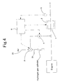
- FIG.4 A block diagram of a regenerating apparatus that is directed to the examples according to the present invention is given in Fig.4 .
- This regenerating apparatus comprises a catalyst 1 for purifying exhaust gas set onto an exhaust system, a heater 2 as a heating means disposed around the catalyst for purifying exhaust gas, a valve 3, a pump 4 disposed between the valve 3 and an exhaust pipe, a sensor 5 which is detecting outlet gas atmosphere from the catalyst 1 for purifying exhaust gas and is disposed downstream side of the catalyst 1 for purifying exhaust gas and a control apparatus 6.
- the valve 3 is connected to an air introducing pipe 30 one end of which is opened to the air through an air filter (not shown) .
- the valve 3 is connected to a hydrogen introducing pipe 31 one end of which is connected to a hydrogen cylinder.
- One of the air introducing pipe 30 and the hydrogen introducing pipe 31 is connected to the pump 4.
- the pump 4 supplies air or hydrogen which is supplied from the air introducing pipe 30 or the hydrogen introducing pipe 31 to an exhaust pipe at upstream side of the catalyst 1 for purifying exhaust gas.
- a control apparatus 6 comprises ECU and controls the heater 2, the valve 3 and the pump 4 by detecting the driving condition of the vehicle and the value of the sensor 5.
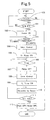
- the control operation of the control apparatus 6 will be explained by means of the flowchart indicated in Fig.5 .
- step 100 the driving record of the engine is investigated and the deterioration degree of the catalyst 1 for purifying exhaust gas is investigated from the relation between the temperature of the exhaust gas and the flow time of the exhaust gas.
- the deterioration degree of the catalyst 1 for purifying exhaust gas is judged to be too small to proceed with the regenerating process, the regenerating process is not carried out.
- the process described below will be carried out in the case when the deterioration is judged to be progressed and the regenerating process is judged to be necessary.
- step 101 whether the fuel is supplying to an engine or not is investigated. In the case that the engine is driven, the regeneration process is not carried out with returning to step 100. In the case that the fuel is not supplied to the engine, the catalyst 1 for purifying exhaust gas is heated by energizing the heater 2 in step 102.
- step 103 when the temperature of the catalyst for purifying exhaust gas is detected to be 400 °C or more, the valve 3 is controlled in step 104 to establish communication between the air introducing pipe 30 and the pump 4. After that, the pump 4 becomes ON in step 105 and air is supplied to the catalyst 1 for purifying exhaust gas through the valve 3 from the air introducing pipe 30.
- the oxidizing step is carried out.
- step 106 when the oxidizing step is judged to be carried out for a predetermined time, the pump 4 becomes OFF in step 107. Then in step 108, the valve 3 is controlled to establish communication between the hydrogen introducing pipe 31 and the pump 4. After that, in step 109, the pump 4 becomes ON again and hydrogen gas is supplied to the catalyst 1 for purifying exhaust gas through the valve 3 from the hydrogen introducing pipe 31. Thus, the reducing step is carried out.
- step 110 the output value of the sensor 5 is input to the control apparatus 6.
- step 111 the outlet gas atmosphere from the catalyst 1 for purifying exhaust gas is investigated. In the case that the outlet gas atmosphere from the catalyst 1 for purifying exhaust gas is not a reducing atmosphere, the process is returned to step 111 again because the reducing step is not sufficiently carried out. In the case that the outlet gas atmosphere from the catalyst 1 for purifying exhaust gas is reducing atmosphere, the reducing step is judged to be completed and in step 112, the heater 2 becomes OFF and the pump 4 becomes OFF.
- the noble metals of the catalyst 1 for purifying exhaust gas are re-dispersed and the purification activities of the catalyst 1 for purifying exhaust gas are reactivated.
- these regenerating processes are carried out under the condition that the fuel supply to the engine is stopped, for example, at the time when vehicle parks, at the time of fuel-cut when the vehicle is driving with a high speed, at the time when a hybrid car is driven by only the electric motor, or at the time of start-up. Because of that, a deteriorated catalyst can be regenerated without interrupting the use of catalyst and also without deteriorating the drivability.
- a feature of a regenerating apparatus that is directed to the examples according to the present invention is illustrated.
- This regenerating apparatus comprises similar construction to that in Example No. 7 except that a plasma generator 7 is disposed on the upstream side of the catalyst 1 for purifying exhaust gas and on the downstream side of the pump 4.
- the heater 2 is not used in Fig.6 .
- Fig.6 only the plasma generator 7 and the catalyst 1 for purifying exhaust gas are illustrated.
- the plasma generator 7 comprises a cylinder electrode 70 which is made of conductive metal and has ⁇ 17 mm in inner diameter and 10 mm in length and a center electrode 71 having a needle shape with ⁇ 1 mm in outer diameter.
- the center electrode 71 is disposed in the center of the cylinder electrode 70.
- the cylinder electrode 70 serves as an earth potential.
- the center electrode 71 is composed so that high voltage of rectangular pulse waveform from a high voltage power supply 72 can be applied with 14.5 kv and 200 Hz.
- a discharge plasma is generated in the plasma generator 7 by applying high voltage power supply to the center electrode 71 under the condition that air or hydrogen gas is supplied to the catalyst 1 for purifying exhaust gas. Then, when the discharge plasma contacts oxygen or hydrogen, active species, such as for example, radicals or ions and the like are generated. When these active species contact the catalyst 1 for purifying exhaust gas, the oxidation or the reduction of the loaded noble metal progresses even under the room temperature.
- the catalyst 1 for purifying exhaust gas can be regenerated under the room temperature. Therefore, the consumption of electric power can be largely saved, compared with the regenerating apparatus indicated in Example No.7.
Landscapes
- Chemical & Material Sciences (AREA)
- Engineering & Computer Science (AREA)
- Chemical Kinetics & Catalysis (AREA)
- Health & Medical Sciences (AREA)
- Materials Engineering (AREA)
- Organic Chemistry (AREA)
- Combustion & Propulsion (AREA)
- Toxicology (AREA)
- Mechanical Engineering (AREA)
- General Engineering & Computer Science (AREA)
- Environmental & Geological Engineering (AREA)
- Biomedical Technology (AREA)
- Analytical Chemistry (AREA)
- General Chemical & Material Sciences (AREA)
- Oil, Petroleum & Natural Gas (AREA)
- Exhaust Gas Treatment By Means Of Catalyst (AREA)
- Catalysts (AREA)
- Exhaust Gas After Treatment (AREA)
Abstract
Description
- The present invention relates to an apparatus and a method for regenerating a deteriorated catalyst for purifying exhaust gas.
- In exhaust system of automobiles, various catalysts for purifying exhaust gas, such as oxidizing catalysts, three-way catalysts and NOx storage-reduction catalysts are loaded. By these catalysts for purifying exhaust gas, harmful components in the exhaust gas are purified. In these catalysts for purifying exhaust gas, catalytic activity is developed by a noble metal, such as Pt (platinum), Rh (rhodium) or Pd (palladium). The noble metal is used under the loaded condition onto a support comprising a porous oxide, such as alumina.
- In order to develop the maximum activity of the noble metal, it is preferable for the particle of the noble metal to be loaded under the high dispersion condition and as fine as possible. Therefore, the noble metals are loaded onto the support by an absorption loading method or an impregnate loading method using solution of soluble noble metal compounds, for example complex salt or nitrate. The noble metals loaded by these methods are loaded under high dispersion condition as fine particles having extreme small particle diameter. Thus, high catalytic activities can be developed.
- However, there has been such a problem of catalyst deterioration that when the catalysts for purifying exhaust gas are exposed to high temperature at the time of using, the fine particles of the noble metals aggregate each other to make coarse particles resulted in the deterioration of the catalyst activities. This aggregation of the noble metal particles is easy to occur particularly in the oxidizing atmosphere. Therefore, particularly, it is problematic to the case of the lean burn engine which can restrain discharge of carbon dioxide. For these problems, the noble metals are loaded in larger quantity than that to be needed anticipating the deterioration. However, these methods need to be considered in view of the cost.
- Accordingly, it is effective to regenerate a deteriorated catalyst for purifying exhaust gas. For example, Japanese Unexamined Patent Application Publication No.
2002-282,710 - However, the above-described method in No.
2002-282,710 - Hence, Japanese Unexamined Patent Application Publication No.
2001-058,121 2001-058121 - Moreover, Japanese Unexamined Patent Application Publication No.
2006-118,500 2006-299,857 - Patent document No. 1: Japanese Unexamined Patent Application Publication No.
2002-282,710 - Patent document No. 2: Japanese Unexamined Patent Application Publication No.
2001-058,121 - Patent document No. 3: Japanese Unexamined Patent Application Publication No.
2006-118,500 - Patent document No. 4: Japanese Unexamined Patent Application Publication No.
2006-299,857 - The present invention has been made in view of the aforementioned problems, and it is an assignment to be achieved to regenerate a deteriorated catalyst without interrupting the use of catalyst and also without deteriorating the drivability.
- A characteristic of the apparatus for regenerating a catalyst for purifying exhaust gas according to the present invention which solves the aforementioned problem lies in the apparatus comprising a heating means which heats the catalyst for purifying exhaust gas including a noble metal at the time of stopping fuel supply to a vehicle engine, an oxidizing gas supplying means which supplies an oxidizing gas to the catalyst for purifying exhaust gas heated by the heating means, a reducing gas supplying means which supplies a reducing gas to the catalyst for purifying exhaust gas heated by the heating means and a switching means which switches over from driving of the oxidizing gas supplying means to driving of the reducing gas supplying means and from driving of the reducing gas supplying means to driving of the oxidizing gas supplying means.
- Another characteristic of an apparatus for regenerating a deteriorated catalyst for purifying exhaust gas according to the present invention lies in the apparatus comprising an oxidizing gas supplying means which supplies the oxidizing gas to the catalyst for purifying exhaust gas including a noble metal, a reducing gas supplying means which supplies a reducing gas to the catalyst for puri fying exhaust gas and a plasma generator which generates discharge plasma in the oxidizing gas or in the reducing gas existing between the oxidizing gas supplying means and the reducing gas supplying means and the catalyst for purifying exhaust gas, the oxidizing gas supplying means supplying an oxidizing gas turned into plasma to the catalyst for purifying exhaust gas and then the reducing gas supplying means supplying a reducing gas turned into plasma to the catalyst for purifying exhaust gas at the time of stopping fuel supply to a vehicle engine.
- Moreover, a characteristic of a method for regenerating a catalyst for purifying exhaust gas according to the present invention lies in a method at the time of stopping fuel supply to a vehicle engine comprising the steps of heating the catalyst for purifying exhaust gas including a noble metal, oxidizing the noble metal by supplying an oxidizing gas to the heated catalyst for purifying exhaust gas and reducing the noble metal under oxidized condition by supplying a reducing gas to the heated catalyst for purifying exhaust gas.
- Furthermore, another characteristic of a method for regenerating a catalyst for purifying exhaust gas according to the present invention lies in a method at the time of stopping fuel supply to a vehicle engine comprising the successive steps of oxidizing a noble metal by supplying an oxidizing gas activated by a discharge plasma to a catalyst for purifying exhaust gas including the noble metal and reducing the noble metal under oxidized condition by supplying a reducing gas activated by a discharge plasma to the catalyst for purifying exhaust gas.
- In accordance with the apparatus and the method for regenerating a catalyst for purifying exhaust gas according to the present invention, a catalyst for purifying exhaust gas is regenerated at the time of stopping fuel supply to a vehicle engine. For example, when the driver' s foot is released from the accelerator pedal during the high speed driving, the fuel supply to a vehicle engine is stopped by the fuel-cut control and the braking force is applied by the engine brake. If the catalyst for purifying exhaust gas is regenerated at that time, the regeneration can be carried out without affecting the drivability.
- Moreover, in the case of hybrid car which uses the electric motor together with the engine, there is a driving mode in which a car is driven only by the electric motor. Under the driving mode, the fuel supply to the engine is also stopped. If the catalyst for purifying exhaust gas is regenerated under the driving mode, the regeneration can be carried out without affecting the drivability.
- Moreover, because the catalyst activity of the catalyst for purifying exhaust gas is reactivated by the regenerating process, it is not necessary to load the noble metal in larger quantity for anticipating the deterioration in advance. Therefore, the loading quantity of the noble metal can be reduced. According to this, the catalyst for purifying exhaust gas can be provided at a lower cost.
- Furthermore, in accordance with the apparatus and the method for regenerating a catalyst for purifying exhaust gas according to the present invention, the reducing step is carried out after the oxidizing step. In the oxidizing step, the catalytic poisons, for example hydrocarbon, which are absorbed on the noble metal are oxidized and removed. The particles of the noble metal become oxidized as pure oxide and the like. In order to carry out the reducing step after that, the particles of the noble metal are reduced and are re-dispersed on the support simultaneously and as a result, the particles of the noble metal become fine. Owing to this, the catalyst activity is reactivated.
- For example, when the catalyst in which Pt is loaded on CeO2 is treated by the oxidizing gas at a predetermined temperature, Pt is oxidized and solid phase reaction occurs between Pt and CeO2 resulting in that the surface of CeO2 is wetted by a Pt component. After that, when these catalysts are treated by the reducing gas at a predetermined temperature, Pt is re-precipitated as metal particles by reducing reaction. At that time, because the affinity between Pt and CeO2 is high, it is considered that the reducing reaction progresses gradually from the surface of the Pt component wetted on the surface of CeO2 and Pt metal is precipitated as fine particle. According to this, Pt particles are re-dispersed as fine particles and the catalyst activity is reactivated.
- Therefore, in accordance with the apparatus and the method for regenerating a catalyst for purifying exhaust gas according to the present invention, a catalyst for purifying exhaust gas can be regenerated in a short period of time with high efficiency of regeneration. Furthermore, if an oxidizing gas and a reducing gas are activated by discharge plasma and then these gases are supplied to a catalyst for purifying exhaust gas, regeneration at room temperature can be carried out. Therefore, a heating means is not needed and the cost can be further saved.
-
-
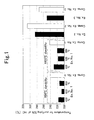
Fig. 1 is a graph for illustrating temperature of purifying 50% of HC; -
Fig. 2 is a graph for illustrating temperature of purifying 50% of HC; -
Fig. 3 is a graph for illustrating temperature of purifying 50% of HC; -
Fig. 4 is a block diagram of a regenerating apparatus that is directed to an example according to the present invention; -
Fig. 5 is a flow chart for illustrating control of a regenerating apparatus that is directed to the example according to the present invention; and -
Fig. 6 is a schematic sectional view for illustrating a feature of an apparatus for regenerating that is directed to another example according to the present invention. -
- 1: Catalyst For Purifying Exhaust Gas;
- 2: Heater;
- 3: Valve;
- 4: Pump;
- 5: Sensor; and
- 6: Control Apparatus
- An apparatus for regenerating according to the present invention comprises a heatingmeans, an oxidizing gas supplyingmeans, a reducing gas supplying means, and a switching means. The heating means can heat a catalyst for purifying exhaust gas at the time of stopping fuel supply to an engine, that is, the time when the catalyst is not heated by exhaust gas. As heating means, it is possible to use an electric heater and the like. Furthermore, a catalyst for purifying exhaust gas with a heater attached may be used. A catalyst for purifying exhaust gas can be heated directly. Moreover, an oxidizing gas and a reducing gas can be heated instead of heating a catalyst for purifying exhaust gas directly. Thus, the catalyst for purifying exhaust gas can be heated indirectly.
- The time of stopping fuel supply to an engine can be the time when vehicles stop or park, the fuel-cut time at driving with a high speed or the time when a hybrid car is driven only by the electric motor.
- The oxidizing gas supplying means is a means which supplies an oxidizing gas to the catalyst for purifying exhaust gas heated by the heating means. Here, an oxidizing gas is a gas which can oxidize noble metals in the heated catalyst for purifying exhaust gas, and the gas including 2% or more oxygen, preferably the gas including 5% or more oxygen can be used. Air existing affluently on the earth can be used.
- In the oxidizing step, the catalyst for purifying exhaust gas is preferably heated to 400 °C∼800 °C by the heating means. When the temperature of the catalyst for purifying exhaust gas is below 400 °C, efficient energy to re-disperse by oxidizing the noble metals may not be obtained. As a result, it is difficult to re-disperse noble metals. Moreover, when the temperature is above 800 °C, because the heat energy is larger than reciprocal action between the support and the noble metals, granular growth of the noble metal is extraordinary. As a result, it is difficult to re-disperse even though the reducing step is carrying out. More preferably, the catalyst for purifying exhaust gas is heated in a range of 550 °C ∼800 °C.
- The reducing gas supplying means is a means which supplies a reducing gas to the catalyst for purifying exhaust gas heated by the heating means after supplying the oxidizing gas. Here, a reducing gas is the gas which reduces oxidized noble metals to noble metals. Fuel such as gasoline, CO, HC, NH3, H2 and the like can be exemplified as a reducing gas. Among these, CO, H2, light HC and NH3 are more preferable.
- It is preferable that in the reducing step, the catalyst for purifying exhaust gas is heated to 100 °C or above by the heating means. When the temperature of the catalyst for purifying exhaust gas is below 100 °C, it is difficult to reduce oxidized noble metals to noble metals. Accordingly, regenerating the catalyst becomes difficult. It is more preferable to heat the catalyst to 300 °C or above.
- An electric pump, an injector and the like can be used for the oxidizing gas supplying means and the reducing gas supplying means. For example, the oxidizing gas supplying means takes air in and supplies the air to the catalyst for purifying exhaust gas. Furthermore, the reducing gas supplying means supplies fuel, urea solution, hydrogen gas or ammonia gas from respective tank or cylinder to the catalyst for purifying exhaust gas.
- Furthermore, it is preferable to supply an oxidizing gas or a reducing gas to the catalyst for purifying exhaust gas utilizing the rotation of a vehicle wheel or the reverse-driving power when the engine is reverse-driven by rotation of the vehicle wheel at the time of stopping fuel supply. This may reduce the consumption of electric power, compared with using an electric pump.
- The process time in the oxidizing step differs depending on the oxygen level in the oxidizing gas and the heating temperature of the catalyst for purifying exhaust gas , but usually the process time in the oxidizing step is about tens of seconds in the case that an air is used as the oxidizing gas. The process time in the reducing step differs depending on the type of the reducing gas or the heating temperature of the catalyst for purifying exhaust gas. Therefore, it is preferable to carry out the reducing step for only the time needed for regeneration. Such desirable time for reducing step can be obtained in advance by researching the relation between the heating temperature of the catalyst for purifying exhaust gas and the reduced degree according to the type of the reducing gas to be used, by experiments.
- It is preferable to carry out the oxidizing step and the reducing step continuously in order. Under the oxidizing condition, purification performance of the noble metal is not obtained sufficiently.
- According to another regenerating apparatus of the present invention, a plasma generator is used, which generates discharge plasma in the oxidizing gas and the reducing gas existing between the oxidizing gas supplying means and the reducing gas supplying means, and the catalyst for purifying exhaust gas. The reactivity improves by the oxidizing gas and the reducing gas activated by the discharge plasma, and the noble metal can be oxidized even under the room temperature and also the noble metal under the oxidized condition can be reduced to the noble metal under the room temperature. Therefore, the heating means becomes unnecessary and the electric energy can be saved.
- The plasma generator is generally constituted to generate a discharge plasma according to the application of the high voltage of 5kV ∼ 50kV. Corona discharge generator, barrier discharge generator, inductively coupled plasma generator, arc discharge generator and the like can be used for plasma generator. Direct-current voltage, alternating voltage, alternating pulse voltage and the like can be used for a high voltage generator. For example, it is possible to activate the oxidizing gas and the reducing gas flowing within the flow path when one or more pairs of electrodes are formed in the flow path of the exhaust gas to generate plasma by discharging between the electrodes. The shape of the electrode is not limited to any particular shape. However, it is preferable to have the shape which is easy to discharge such as for example fine line shape, needle shape, edge shape and the like. It is also preferable to cover the electrode with dielectric.
- In the case using a plasma generator, ozone, OH radical, NO and the like can be used in addition to the gas including 2% or more oxygen, the gas including 5% or more oxygen, and air as an oxidizing gas. Moreover, as a reducing gas, N radical, H radical and the like can be used in addition to fuel such as gasoline, CO, HC, NH3, H2 and the like. Ozone, OH radical, NO, N radical and H radical may exist before discharge and may be generated after generating of discharge plasma.
- Oxidizing catalysts, three-way catalysts, NOx storage-reduction catalysts and the like can be used as the catalyst for purifying exhaust gas in the present invention. Alumina, titania, ceria, zirconia, ceria-zirconia solid solutions and the like are exemplified as the support. It is preferable to include at least ceria in the support. Furthermore, Pt, Rh, Pd, Ir (iridium) and the like are exemplified as noble metal loaded onto the support. It is preferable to include at least Pt as a noble metal. The reason is that in the case of Pt loaded onto the support including ceria, the effect of the present invention is remarkable. Moreover, the loading quantity of the noble metal in the catalyst for purifying exhaust gas is not limited to any particular quantity. The general loading quantity can be used.
- Hereinafter, the present invention will be explained concretely by means of the examples and the comparative examples.
- <Preparation of pellet catalyst>
- CeO2-ZrO2 solid solutions powder (CeO2:ZrO2=60:40 in weight ratio) was prepared and a predetermined amount of diammine dinitro platinum solution in a predetermined concentration was impregnated to the CeO2-ZrO2 solid solutions powder. Thereafter, this was dried at 120 °C and calcined at 500 °C for 2 hours, thereby preparing a Pt/CeO2-ZrO2 catalyst powder on which 1 mass (weight) % of Pt was loaded. This Pt/CeO2-ZrO2 catalyst powder was pelletized by a conventional method, thereby preparing a pellet catalyst. This pellet catalyst was used in the regeneration process described below.
- (Example No. 1)
- The pellet catalyst described above was put into a cannulated furnace. Nitrogen durability test was carried out, in which the pellet catalysts are held under the nitrogen gas atmosphere for 5 hours at 950 °C and 1000 °C, respectively. The catalysts after the nitrogen durability test were subjected to the oxidizing step where the catalysts are held for 2 hours at 400 °C, 600 °C and 800 °C, respectively and then the respective oxidized catalysts were subjected to the reducing step where the oxidized catalysts are held for 15 minutes at 500 °C in nitrogen gas including 3 volume% H2.
- (Comparative Example No. 1)
- The respective catalysts after nitrogen durability test carried out in the same manner as Example No. 1 were not subjected to the oxidizing step. And then the reducing step was only carried out for the respective catalysts in the same manner as Example No. 1.
- (Example No. 2)
- The pellet catalyst described above was put into a cannulated furnace. RL durability test was carried out, in which the pellet catalysts are held under the atmosphere which is repeating rich gas atmosphere (CO:2%,N2:balance) and lean gas atmosphere (O2:5%,N2:balance) for each 120 seconds alternately, for 5 hours at 1000 °C. The oxidizing step were carried out the catalysts after RL durability test, where the catalysts are held for 2 hours at 600 °C in air and then the reducing step were carried out the oxidized catalysts, where the oxidized catalysts are held for 15 minutes at 500 °C in nitrogen gas including 3 volume% H2.
- (Comparative Example No. 2)
- The catalysts after RL durability test carried out in the same manner as Example No. 2 were not subjected to the oxidizing step. And then the reducing step was only carried out the catalysts in the same manner as Example No. 2.
- (Example No. 3)
- The pellet catalyst described above was put into an electric furnace. Air durability test was carried out, in which the pellet catalysts are held under the air for 5 hours at 1000 °C. The catalysts after air durability test were subjected to the oxidizing step where the catalysts are held for 2 hours at 600 °C in air and then the oxidized catalysts were subjected to the reducing step where the oxidized catalysts are held for 15 minutes at 500 °C in nitrogen gas including 3 volume% H2.
- (Comparative Example No. 3)
- The catalysts after air durability test carried out in the same manner as Example No. 3 were not subjected to the oxidizing step. And then the reducing step was only carried out the catalysts in the same manner as Example No. 3.
- <Experimental Example No. 1>
- 1 (one) gram of the respective catalysts regenerated according to Example Nos. 1∼3 and Comparative Example Nos.1∼3 was filled into the respective silica tubes in the tubular furnace. While the model gas indicated in Table 1 was flowed through the catalysts at a rate of 10 L/min, the catalysts were heated to 100 °C∼500 °C at a temperature rise rate of 20 °C /min in the tubular furnace. HC purification rate during this period was measured continuously and the temperature for purifying 50 % of HC was measured respectively. The results are given in Table 2 and
Fig. 1 . -
[TABLE 1] CO (%) C3H6 (ppm) NO (ppm) CO2 (%) O2 (%) H2O (%) N2 0.65 1000 1500 10 0.7 5 balance -
[TABLE 2] Durabilty Test Temperature Temperature at Oxidizing step Temperature for purifying 50% of HC Ex. No 1 950°C 400°C 217°C 600°C 208°C 800°C 214°C Comp. Ex. No 1 950°C - 241 °C Ex. No 1 1000°C 400°C 230°C 600°C 218°C 800°C 220°C Comp. Ex.No.1 1000°C - 242°C Ex. No 2 1000°C 600°C 285°C Comp. Ex. No 2 1000°C - 307°C Ex. No 3 1000°C 600°C 249°C Comp. Ex. No 3 1000°C - 273°C - From Table 2 and
Fig. 1 , it is understood that the activity of purification of the catalyst according to Example No. 1 was superior compared with the catalyst according to Comparative Example No.1. That is, it is apparent that the catalyst deteriorated at the nitrogen durability test was regenerated by carrying out the oxidizing step and the reducing step. - Moreover, the activity of purification of the catalyst according to Example No. 2 was superior compared with the catalyst according to Comparative Example No. 2 and the activity of purification of the catalyst according to Example No. 3 was superior compared with the catalyst according to Comparative Example No.3. That is, even if the conditions of the durability test are different, it is apparent that the catalyst deteriorated at the durability test was regenerated by carrying out the oxidizing step and the reducing step.
- Furthermore, in Example No.3, air durability test in which catalysts are held under the air for 5 hours at 1000 °C was similar to that in Comparative Example No.3. The difference between Comparative Example No.3 and Example No. 3 is whether the oxidizing step (the catalysts are held under the air for 2 hours at 600 °C) was carried out or not. However, because the regeneration of the catalysts in Example No. 3 was progressed compared with that in Comparative Example No. 3, it is suggested that the oxidizing step is preferably carried out below 1000 °C.
- < Preparation of the first honeycomb catalyst >
- A honeycomb substrate, which was made of cordierite (cell density : 600 cpsi, wall thickness : 75 µm, diameter : 103mm, length : 105 mm, 0.875 L), was prepared. The slurry, which includes 120 parts by mass of Pt/CeO2-ZrO2 catalyst powder similar to that obtained at the preparation of the pellet catalyst, and 10 parts by mass of a ceria sol binder, was wash-coated onto the honeycomb substrate and then the honeycomb catalyst was prepared. In the coating layer, 120 g of Pt / CeO2 - ZrO2 catalyst powder per 1 L of honeycomb catalyst was included and 0.6 g of Pt was loaded per 1 L of honeycomb catalyst.
- (Example No. 4)
- The first honeycomb catalyst described above was fit onto an exhaust system of a 4.3-L gasoline engine. The actual durability test was conducted for 50 hours under a condition that the catalyst-bed temperature is 750 °C and 3-second fuel cut control and 7-second feed back control are repeated alternately. The 7-second feed back control is controlled under stoichiometry atmosphere of A/F=14.6, wherein A/F means air-fuel ratio.
- Furthermore, the fuel cut control is the control in which fuel supply to the engine is cut under the condition that the vehicle wheel is rotating. During the fuel cut control, only the air is exhausted from the engine and no exhaust gas is exhausted from the engine. Moreover, the feed back control controls the air-fuel ratio within a predetermined range by controlling a fuel supply amount through detection of oxygen level in the exhaust gas. The exhaust gas atmosphere in this case changes a few to rich atmosphere or lean atmosphere referencing stoichiometry atmosphere.
- The catalysts after the actual durability test described above were subjected to the oxidizing step for holding for 2 hours at 800 °C in the air, and then the oxidized catalysts were subjected to the reducing step for holding for 1 hour at 700°C in nitrogen gas including 3 volume% CO.
- (Comparative Example No. 4)
- The first honeycomb catalyst described above was fit onto an exhaust system of a engine similar to that in Example No. 4 and the actual durability test was carried out in the manner similar to that in Example No. 4. The oxidizing step and the reducing step were not carried out.
- < Preparation of the second honeycomb catalyst >
- CeO2-ZrO2 solid solutions powder (CeO2:ZrO2=60:40 in weight ratio) was prepared and a predetermined amount of barium acetate aqueous solution in a predetermined concentration was impregnated to the CeO2-ZrO2 solid solutions powder. Thereafter this was dried at 120 °C and calcined at 500 °C for 2 hours, thereby 0.71 mass (weight) % of Ba was loaded. After that, a predetermined amount of diammine dinitro platinum solution in a predetermined concentration was impregnated. Thereafter this was dried at 120 °C and calcined at 500 °C for 2 hours, thereby 0.5 mass (weight) % of Pt was loaded. Then Pt-Ba/CeO2-ZrO2 catalyst powder was prepared.
- On the other hand, a honeycomb substrate, which was made of cordierite (cell density : 600 cpsi, wall thickness : 75 µm, diameter : 103 mm, length : 105 mm, 0.875 L), was prepared. The slurry, which includes 120 parts by mass of Pt-Ba/CeO2-ZrO2 catalyst powder and 10 parts by mass of a ceria sol binder was wash-coated onto the honeycomb substrate and then the honeycomb catalyst was prepared. In the coating layer, 120 g of Pt-Ba/CeO2-ZrO2 catalyst powder per 1 L of honeycomb catalyst was included and 0.6 g of Pt was loaded per 1 L of honeycomb catalyst.
- (Example No. 5)
- The second honeycomb catalyst described above was fit onto an exhaust system of an engine similar to that in Example No. 4 and the actual durability test was conducted in the manner similar to that in Example No. 4. The catalyst after the actual durability test was subjected to 2 cycles of 6-second fuel cut control under a condition that the catalyst-bed temperature is 750 °C ( an oxidizing step) and 54-second feed back control for controlling A/F under stoichiometry atmosphere of A/F=14.6( a reducing step),wherein A/F means air-fuel ratio.
- (Comparative Example No. 5)
- The second honeycomb catalyst described above was fit onto an exhaust system of an engine similar to that in Example No. 4 and the actual durability test was carried out in the manner similar to that in Example No. 4. The oxidizing step and the reducing step were not carried out.
- <Experimental Example No. 2>
- The respective catalysts regenerated according to Example Nos. 4, 5 and Comparative Example Nos.4, 5 were fit onto an exhaust system of an in-line, 4-cylinder, 2.4-L gasoline engine and were burnt at theoretical air-fuel ratio until the catalyst-bed temperature became 500 °C after starting the engine. After that, the temperature of the gas flowing into the catalysts was risen from 200 °C to 450 °C at a temperature rise rate of 10 °C /min by using a heat exchanger. HC purification rate during the temperature changes was measured continuously and the temperature for purifying 50 % of HC was measured. The results are given in Table 3 and
Fig. 2 . -
[TABLE 3] Durabilty Test Temperature Temperature at Oxidizing step Temperature for purifying 50% of HC Ex.No.4 750°C 800°C 361°C Comp. Ex. No 4 750°C - 430°C Ex. No 5 750°C 750°C 421°C Comp. Ex. No 5 750°C - 438°C - From Table 3 and
Fig. 2 , it is understood that the activity of purification of the catalyst according to Example No. 4 was superior compared with the catalyst according to Comparative Example No. 4 and the activity of purification of the catalyst according to Example No. 5 was superior compared with the catalyst according to Comparative Example No. 5. That is, it is apparent that the catalyst deteriorated at the durability test was regenerated by carrying out the oxidizing step and the reducing step. - (Example No. 6)
- The first honeycomb catalyst described above was fit onto an exhaust system of an engine similar to that in Example No. 4 and the actual durability test was conducted in the manner similar to that in Example No. 4.
- The test pieces having 30 mm in diameter and 50 mm in length were cut from the first honeycomb catalyst after the actual durability test. These test pieces were subjected to the oxidizing step where the test pieces are held for 10 seconds, 30 seconds, 60 seconds, 120 seconds, 180 seconds, 600 seconds, respectively at 700 °C in nitrogen gas including 8 volume% O2. Continuously, the test pieces were subjected to the reducing step where the test pieces are held for 10 minutes at 450 °C in the rich model gas indicated in Table 4.
-
[TABLE 4] CO (%) C3H6 (%C) NO (%) CO2 (%) O2 (%) H2O (%) N2 0.7 0.16 0.12 8 0:6465 3 balance - The first honeycomb catalyst described above was fit onto an exhaust system of an engine similar to that in Example No. 4 and the actual durability test was carried out in the manner similar to that in Example No. 4.
- The test pieces having 30 mm in diameter and 50 mm in length were cut from the first honeycomb catalyst after the actual durability test. These test pieces were subjected to the reducing step where the test pieces are held for 10 minutes at 450 °C in the rich model gas indicated in Table 4. That is, except that the oxidizing step was not carried out, it was in the same manner as that of Example No. 6.
- <Experimental Example No. 3>
- The respective catalysts regenerated according to Example No. 6 and Comparative Example No.6 were fit onto an exhaust system of an in-line, 4-cylinder, 2.4-L gasoline engine and the temperature for purifying 50% of HC was measured in the same manner in that of Experimental Example No. 2. The results are given in
Fig. 3 . - From
Fig. 3 , it is understood that the activity of purification of the catalyst according to Example No. 6 was superior compared with the catalyst according to Comparative Example No. 6. That is, it is apparent that the catalyst deteriorated at the actual durability test was regenerated by carrying out the oxidizing step and the reducing step. And it is also apparent that the longer the process time in the oxidizing step was the higher the activity of purification became and the oxidizing step was essential before the reducing step. - (Example No. 7)
- A block diagram of a regenerating apparatus that is directed to the examples according to the present invention is given in
Fig.4 . This regenerating apparatus comprises acatalyst 1 for purifying exhaust gas set onto an exhaust system, aheater 2 as a heating means disposed around the catalyst for purifying exhaust gas, avalve 3, apump 4 disposed between thevalve 3 and an exhaust pipe, asensor 5 which is detecting outlet gas atmosphere from thecatalyst 1 for purifying exhaust gas and is disposed downstream side of thecatalyst 1 for purifying exhaust gas and acontrol apparatus 6. - The
valve 3 is connected to anair introducing pipe 30 one end of which is opened to the air through an air filter (not shown) . Thevalve 3 is connected to ahydrogen introducing pipe 31 one end of which is connected to a hydrogen cylinder. One of theair introducing pipe 30 and thehydrogen introducing pipe 31 is connected to thepump 4. Thepump 4 supplies air or hydrogen which is supplied from theair introducing pipe 30 or thehydrogen introducing pipe 31 to an exhaust pipe at upstream side of thecatalyst 1 for purifying exhaust gas. - A
control apparatus 6 comprises ECU and controls theheater 2, thevalve 3 and thepump 4 by detecting the driving condition of the vehicle and the value of thesensor 5. Hereinafter, the control operation of thecontrol apparatus 6 will be explained by means of the flowchart indicated inFig.5 . - First, in
step 100, the driving record of the engine is investigated and the deterioration degree of thecatalyst 1 for purifying exhaust gas is investigated from the relation between the temperature of the exhaust gas and the flow time of the exhaust gas. In the case when the deterioration degree of thecatalyst 1 for purifying exhaust gas is judged to be too small to proceed with the regenerating process, the regenerating process is not carried out. However, in the case when the deterioration is judged to be progressed and the regenerating process is judged to be necessary, the process described below will be carried out. - In
step 101, whether the fuel is supplying to an engine or not is investigated. In the case that the engine is driven, the regeneration process is not carried out with returning to step 100. In the case that the fuel is not supplied to the engine, thecatalyst 1 for purifying exhaust gas is heated by energizing theheater 2 instep 102. - Then, in
step 103, when the temperature of the catalyst for purifying exhaust gas is detected to be 400 °C or more, thevalve 3 is controlled instep 104 to establish communication between theair introducing pipe 30 and thepump 4. After that, thepump 4 becomes ON instep 105 and air is supplied to thecatalyst 1 for purifying exhaust gas through thevalve 3 from theair introducing pipe 30. Thus, the oxidizing step is carried out. - In
step 106, when the oxidizing step is judged to be carried out for a predetermined time, thepump 4 becomes OFF instep 107. Then instep 108, thevalve 3 is controlled to establish communication between thehydrogen introducing pipe 31 and thepump 4. After that, instep 109,thepump 4 becomes ON again and hydrogen gas is supplied to thecatalyst 1 for purifying exhaust gas through thevalve 3 from thehydrogen introducing pipe 31. Thus, the reducing step is carried out. - In
step 110, the output value of thesensor 5 is input to thecontrol apparatus 6. Instep 111, the outlet gas atmosphere from thecatalyst 1 for purifying exhaust gas is investigated. In the case that the outlet gas atmosphere from thecatalyst 1 for purifying exhaust gas is not a reducing atmosphere, the process is returned to step 111 again because the reducing step is not sufficiently carried out. In the case that the outlet gas atmosphere from thecatalyst 1 for purifying exhaust gas is reducing atmosphere, the reducing step is judged to be completed and instep 112, theheater 2 becomes OFF and thepump 4 becomes OFF. - According to these regenerating process described above, the noble metals of the
catalyst 1 for purifying exhaust gas are re-dispersed and the purification activities of thecatalyst 1 for purifying exhaust gas are reactivated. Thus, these regenerating processes are carried out under the condition that the fuel supply to the engine is stopped, for example, at the time when vehicle parks, at the time of fuel-cut when the vehicle is driving with a high speed, at the time when a hybrid car is driven by only the electric motor, or at the time of start-up. Because of that, a deteriorated catalyst can be regenerated without interrupting the use of catalyst and also without deteriorating the drivability. - (Example No. 8)
- In
Fig. 6 , a feature of a regenerating apparatus that is directed to the examples according to the present invention is illustrated. This regenerating apparatus comprises similar construction to that in Example No. 7 except that aplasma generator 7 is disposed on the upstream side of thecatalyst 1 for purifying exhaust gas and on the downstream side of thepump 4. Theheater 2 is not used inFig.6 . In other words, inFig.6 , only theplasma generator 7 and thecatalyst 1 for purifying exhaust gas are illustrated. - The
plasma generator 7 comprises acylinder electrode 70 which is made of conductive metal and has φ 17 mm in inner diameter and 10 mm in length and acenter electrode 71 having a needle shape withφ 1 mm in outer diameter. Thecenter electrode 71 is disposed in the center of thecylinder electrode 70. Thecylinder electrode 70 serves as an earth potential. Thecenter electrode 71 is composed so that high voltage of rectangular pulse waveform from a highvoltage power supply 72 can be applied with 14.5 kv and 200 Hz. - That is, in accordance with the regenerating apparatus shown in
Fig.6 according to the present invention, a discharge plasma is generated in theplasma generator 7 by applying high voltage power supply to thecenter electrode 71 under the condition that air or hydrogen gas is supplied to thecatalyst 1 for purifying exhaust gas. Then, when the discharge plasma contacts oxygen or hydrogen, active species, such as for example, radicals or ions and the like are generated. When these active species contact thecatalyst 1 for purifying exhaust gas, the oxidation or the reduction of the loaded noble metal progresses even under the room temperature. - Therefore, in accordance with the regenerating apparatus shown in
Fig. 6 according to the present invention, even if theheater 2 is not used, thecatalyst 1 for purifying exhaust gas can be regenerated under the room temperature. Therefore, the consumption of electric power can be largely saved, compared with the regenerating apparatus indicated in Example No.7.
Claims (10)
- An apparatus for regenerating a catalyst for purifying exhaust gas, comprising:a heating means which heats said catalyst for purifying exhaust gas including a noble metal at the time of stopping fuel supply to a vehicle engine;an oxidizing gas supplying means which supplies an oxidizing gas to said catalyst for purifying exhaust gas heated by said heating means;a reducing gas supplying means which supplies a reducing gas to said catalyst for purifying exhaust gas heated by said heating means; anda switching means which switches over from driving of said oxidizing gas supplying means to driving of said reducing gas supplying means, and from driving of said reducing gas supplying means to driving of said oxidizing gas supplying means.
- An apparatus for regenerating a catalyst for purifying exhaust gas, comprising:an oxidizing gas supplying means which supplies an oxidizing gas to said catalyst for purifying exhaust gas including a noble metal;a reducing gas supplying means which supplies a reducing gas to said catalyst for purifying exhaust gas; anda plasma generator which generates discharge plasma in said oxidizing gas or said reducing gas existing between said oxidizing gas supplying means and said reducing gas supplying means, and said catalyst for purifying exhaust gas,said oxidizing gas supplying means supplying an oxidizing gas turned into plasma to said catalyst for purifying exhaust gas and then said reducing gas supplying means supplying a reducing gas turned into plasma to said catalyst for purifying exhaust gas at the time of stopping fuel supply to a vehicle engine.
- The apparatus for regenerating a catalyst for purifying exhaust gas set forth in claim 1 or 2, wherein said catalyst for purifying exhaust gas comprises:a support which includes at least ceria; anda platinum loaded onto said support.
- A method for regenerating a catalyst for purifying exhaust gas at the time of stopping fuel supply to a vehicle engine, comprising the successive steps of:heating said catalyst for purifying exhaust gas including a noble metal;oxidizing said noble metal by supplying an oxidizing gas to said heated catalyst for purifying exhaust gas; andreducing said noble metal under oxidized condition by supplying a reducing gas to said heated catalyst for purifying exhaust gas.
- The method for regenerating a catalyst for purifying exhaust gas set forth in claim 4, wherein said engine is reverse-driven by rotation of a vehicle wheel at the time of stopping fuel supply.
- The method for regenerating a catalyst for purifying exhaust gas set forth in claim 4, wherein said oxidizing step is carried out under the condition that said catalyst for purifying exhaust gas is heated within 400 °C∼800 °C.
- The method for regenerating a catalyst for purifying exhaust gas set forth in claim 4, wherein said reducing step is carried out under the condition that said catalyst for purifying exhaust gas is heated to 100 °C or above.
- The method for regenerating a catalyst for purifying exhaust gas set forth in claim 4, wherein said oxidizing gas includes 2% or more oxygen gas.
- A method for regenerating a catalyst for purifying exhaust gas at the time of stopping fuel supply to a vehicle engine, comprising the successive steps of:oxidizing a noble metal by supplying an oxidizing gas activated by a discharge plasma to a catalyst for purifying exhaust gas including said noble metal; andreducing said noble metal under oxidized condition by supplying a reducing gas activated by a discharge plasma to said catalyst for purifying exhaust gas.
- The method for regenerating a catalyst for purifying exhaust gas set forth in any one of claims 4∼9, wherein said catalyst for purifying exhaust gas comprises:a support which includes at least ceria; anda platinum loaded onto said support.
Applications Claiming Priority (2)
| Application Number | Priority Date | Filing Date | Title |
|---|---|---|---|
| JP2007124754A JP4758391B2 (en) | 2007-05-09 | 2007-05-09 | Exhaust gas purification catalyst regeneration device and regeneration method |
| PCT/JP2008/058636 WO2008140042A1 (en) | 2007-05-09 | 2008-05-09 | Device and method for regenerating exhaust purification catalyst |
Publications (2)
| Publication Number | Publication Date |
|---|---|
| EP2145671A1 true EP2145671A1 (en) | 2010-01-20 |
| EP2145671A4 EP2145671A4 (en) | 2011-06-22 |
Family
ID=40002238
Family Applications (1)
| Application Number | Title | Priority Date | Filing Date |
|---|---|---|---|
| EP08752519A Withdrawn EP2145671A4 (en) | 2007-05-09 | 2008-05-09 | DEVICE AND METHOD FOR REGENERATING AN EXHAUST PURIFYING CATALYST |
Country Status (6)
| Country | Link |
|---|---|
| US (1) | US8601794B2 (en) |
| EP (1) | EP2145671A4 (en) |
| JP (1) | JP4758391B2 (en) |
| KR (1) | KR101114167B1 (en) |
| CN (1) | CN101678272B (en) |
| WO (1) | WO2008140042A1 (en) |
Cited By (1)
| Publication number | Priority date | Publication date | Assignee | Title |
|---|---|---|---|---|
| EP2654929B1 (en) * | 2010-12-21 | 2020-02-12 | Johnson Matthey Public Limited Company | Oxidation catalyst for a lean burn internal combustion engine |
Families Citing this family (20)
| Publication number | Priority date | Publication date | Assignee | Title |
|---|---|---|---|---|
| EP2578822A4 (en) * | 2010-05-25 | 2016-04-27 | Toyota Motor Co Ltd | CONTROL DEVICE FOR INTERNAL COMBUSTION ENGINE |
| CN103025590B (en) * | 2010-07-26 | 2015-07-29 | 丰田自动车株式会社 | The control setup of motor vehicle driven by mixed power |
| CN103140402A (en) * | 2010-10-21 | 2013-06-05 | 日野自动车株式会社 | Regeneration control device, hybrid vehicle, regeneration control method, and program |
| AU2011355953A1 (en) * | 2011-01-21 | 2013-05-02 | Hino Motors, Ltd. | Regeneration control device, hybrid automobile, regeneration control method, and program |
| KR101289861B1 (en) * | 2011-07-21 | 2013-07-24 | (주) 빛과환경 | Volatile organic compounds remover with continuous adsorption and regeneration functions |
| DE112012002971B4 (en) | 2011-08-06 | 2024-02-29 | Cummins Inc. | Diesel-electric hybrid powertrains and emissions testing therefor |
| KR101339966B1 (en) * | 2011-10-20 | 2013-12-11 | 한국과학기술원 | Activation Method of Transition Metal Nanoparticle Catalyst |
| US10155908B2 (en) | 2012-03-07 | 2018-12-18 | Research Triangle Institute | Catalyst compositions and use thereof in catalytic biomass pyrolysis |
| WO2013134391A1 (en) | 2012-03-07 | 2013-09-12 | Research Triangle Institute | Catalytic biomass pyrolysis process |
| JP5888301B2 (en) * | 2013-09-06 | 2016-03-22 | トヨタ自動車株式会社 | Control method for internal combustion engine |
| JP6270028B2 (en) * | 2013-12-24 | 2018-01-31 | 日産自動車株式会社 | Internal combustion engine system |
| US10456743B2 (en) | 2015-08-31 | 2019-10-29 | Hitachi Chemical Company, Ltd. | Exhaust-gas treatment equipment and gas-capture-material deterioration-state estimating method |
| WO2017078377A2 (en) | 2015-11-05 | 2017-05-11 | 한국기계연구원 | Apparatus for removing contaminant in process discharge gas, which includes means for regenerating contaminated oxidation catalyst |
| CN107035470B (en) * | 2017-05-17 | 2019-03-05 | 江苏大学 | A kind of dpf regeneration system and control method optimizing flow field |
| CN107725151A (en) * | 2017-08-30 | 2018-02-23 | 昆明理工大学 | A kind of automobile exhaust gas purifying installation |
| US10677122B2 (en) * | 2017-09-08 | 2020-06-09 | Ford Global Technologies, Llc | Method and system for a particulate filter |
| FR3088959B1 (en) * | 2018-11-27 | 2020-12-11 | Renault Sas | Method of controlling a traction device for a motor vehicle comprising an electrically heated combustion gas treatment device |
| CN110026253B (en) * | 2019-04-22 | 2022-02-01 | 南京信息工程大学 | Regeneration method of synergetic denitration and dioxin removal catalyst |
| CN111167525A (en) * | 2020-01-09 | 2020-05-19 | 中国科学院电工研究所 | A kind of treatment process and device of waste balance agent plasma |
| CN115957826B (en) * | 2023-01-18 | 2023-08-04 | 常熟理工学院 | Low-temperature plasma irradiation regeneration method of waste denitration catalyst and regenerated denitration catalyst |
Family Cites Families (18)
| Publication number | Priority date | Publication date | Assignee | Title |
|---|---|---|---|---|
| JPS5120090A (en) * | 1974-08-12 | 1976-02-17 | Toyota Motor Co Ltd | Shokubaino saiseishorihoho |
| US5254519A (en) * | 1990-02-22 | 1993-10-19 | Engelhard Corporation | Catalyst composition containing platinum and rhodium components |
| JP2950014B2 (en) * | 1992-05-15 | 1999-09-20 | 三菱自動車工業株式会社 | How to drive a hybrid car |
| US5716586A (en) * | 1993-06-03 | 1998-02-10 | Kabushiki Kaisha Toyoda Jidoshokki Seisakusho | Exhaust gas purifier |
| US6040265A (en) * | 1996-02-21 | 2000-03-21 | Asec Manufacturing General Partnership | Methods of making highly dispersed substantially uniform cerium and zirconium mixed-metal-oxide composite supports for exhaust conversion catalysts |
| JP2000202309A (en) | 1999-01-18 | 2000-07-25 | Toyota Central Res & Dev Lab Inc | Regeneration method of exhaust gas purification catalyst |
| JP3858137B2 (en) | 1999-08-23 | 2006-12-13 | 日立造船株式会社 | Apparatus and method for decomposing and treating harmful substances in exhaust gas |
| JP3618269B2 (en) * | 1999-12-06 | 2005-02-09 | トヨタ自動車株式会社 | Control device when vehicle fuel supply is stopped |
| DE10042010C2 (en) * | 2000-08-26 | 2002-08-22 | Bosch Gmbh Robert | Exhaust gas treatment device |
| JP4001723B2 (en) | 2001-03-28 | 2007-10-31 | 本田技研工業株式会社 | Method for recovering catalyst performance of reforming catalyst device |
| JP2004176703A (en) * | 2002-10-02 | 2004-06-24 | Toshiba Corp | Gas purifying apparatus, gas purifying method, and discharge reactant used in gas purifying apparatus |
| DE502005007492D1 (en) | 2004-10-01 | 2009-07-30 | Eberspaecher J Gmbh & Co | Exhaust system for an internal combustion engine and associated operating method |
| JP2006112347A (en) * | 2004-10-15 | 2006-04-27 | Toyota Motor Corp | Exhaust gas purification device for internal combustion engine |
| JP4151645B2 (en) * | 2004-11-29 | 2008-09-17 | トヨタ自動車株式会社 | Exhaust gas purification apparatus and control method thereof |
| JP4513629B2 (en) * | 2005-03-29 | 2010-07-28 | トヨタ自動車株式会社 | Vehicle control device |
| JP2006299857A (en) | 2005-04-18 | 2006-11-02 | Nissan Motor Co Ltd | Exhaust gas purification system for internal combustion engine |
| JP4730947B2 (en) * | 2005-07-22 | 2011-07-20 | 株式会社豊田中央研究所 | Method for regenerating exhaust gas purification catalyst |
| JP5120090B2 (en) | 2008-06-18 | 2013-01-16 | トヨタ紡織株式会社 | Sponge sheet cutting apparatus and scissor sheet cutting method |
-
2007
- 2007-05-09 JP JP2007124754A patent/JP4758391B2/en not_active Expired - Fee Related
-
2008
- 2008-05-09 EP EP08752519A patent/EP2145671A4/en not_active Withdrawn
- 2008-05-09 KR KR1020097023118A patent/KR101114167B1/en not_active Expired - Fee Related
- 2008-05-09 CN CN2008800152505A patent/CN101678272B/en not_active Expired - Fee Related
- 2008-05-09 WO PCT/JP2008/058636 patent/WO2008140042A1/en not_active Ceased
- 2008-05-09 US US12/599,079 patent/US8601794B2/en not_active Expired - Fee Related
Non-Patent Citations (6)
| Title |
|---|
| A MARTINEZ ARIAS ET AL.: "INFLUENCE OF MUTUAL PLATINUM DISPERSED CERIA INTERACTIONS ON THE PROMOTING EFFECT OF CERIA FOR THE CO OXIDATION REACTION IN A Pt/CeO2/Al2O3 CATALYST", J. PHYS.CHEM B, vol. 102, 31 December 1998 (1998-12-31), pages 4357-4365, XP002636195, * |
| ANNA HOLMGREN ET AL.: "INFLUENCE OF PRE-TREATMENT ON THE LOW-TEMPERATURE ACTIVITY OF PT/CERIA", APPLIED CATALYSIS B: ENVIRONMENTAL, vol. 22, 31 December 1999 (1999-12-31), pages 49-61, XP002636193, * |
| CHANG-JU LIU ET AL.: "PLASMA APPLICATION FOR MORE ENVIRONMENTALLY FRIENDLY CATALYST PREPARATION", PURE APPL.CHEM., vol. 78, no. 6, 31 December 2006 (2006-12-31), pages 1227-1238, XP002636194, * |
| RUUD SNEL: "LABORATORY REACTOR SYSTEM FOR THE EVALUATION OF CATALYSTS IN GAS-PHASE REACTIONS UNDER REALISTIC PROCESS CONDITIONS", IND. ENG. CHEM. FUNDAM., vol. 24, 31 December 1985 (1985-12-31), pages 257-260, XP002636192, * |
| See also references of WO2008140042A1 * |
| X. WANG ET AL.: "DEACTIVATION MECHANISMS FOR Pd/CERIA DURING THE WATER-GAS-SHIFT REACTION", JOURNAL OF CATALYSIS, vol. 212, 31 December 2002 (2002-12-31), pages 225-230, XP002636196, * |
Cited By (1)
| Publication number | Priority date | Publication date | Assignee | Title |
|---|---|---|---|---|
| EP2654929B1 (en) * | 2010-12-21 | 2020-02-12 | Johnson Matthey Public Limited Company | Oxidation catalyst for a lean burn internal combustion engine |
Also Published As
| Publication number | Publication date |
|---|---|
| CN101678272B (en) | 2013-04-03 |
| CN101678272A (en) | 2010-03-24 |
| JP2008279343A (en) | 2008-11-20 |
| US8601794B2 (en) | 2013-12-10 |
| KR101114167B1 (en) | 2012-02-22 |
| JP4758391B2 (en) | 2011-08-24 |
| EP2145671A4 (en) | 2011-06-22 |
| US20100293921A1 (en) | 2010-11-25 |
| WO2008140042A1 (en) | 2008-11-20 |
| KR20090128537A (en) | 2009-12-15 |
Similar Documents
| Publication | Publication Date | Title |
|---|---|---|
| US8601794B2 (en) | Apparatus and method for regenerating catalyst for purifying exhaust gas | |
| JP6450540B2 (en) | Lean burn IC engine exhaust system | |
| US12345193B2 (en) | Exhaust gas purification system for a gasoline engine | |
| CN102245295B (en) | Dual functional catalysts for decomposition and oxidation of nitrogen monoxide, mixed catalysts for exhaust-gas reducing device including the same, and preparation method thereof | |
| KR20130040881A (en) | Method of depleting nitrous oxide in exhaust gas after-treatment for lean-burn engines | |
| US11547969B2 (en) | Exhaust gas purification system for a gasoline engine | |
| EP3639922B1 (en) | Exhaust gas purification system for a gasoline engine | |
| US11859526B2 (en) | Exhaust gas purification system for a gasoline engine | |
| US11377993B2 (en) | Exhaust gas purification system for a gasoline engine | |
| JPWO2018025827A1 (en) | Cold start compatible urea SCR system | |
| WO2020079141A1 (en) | Exhaust gas purification system for a gasoline engine | |
| JP2003531721A (en) | Exhaust gas purification method and apparatus | |
| WO2020079143A1 (en) | Exhaust gas purification system for a gasoline engine | |
| JPH07102957A (en) | Device and method for exhaust emission control | |
| EP4106915A1 (en) | Diesel oxidation catalyst | |
| JP4372764B2 (en) | Exhaust gas purification device |
Legal Events
| Date | Code | Title | Description |
|---|---|---|---|
| PUAI | Public reference made under article 153(3) epc to a published international application that has entered the european phase |
Free format text: ORIGINAL CODE: 0009012 |
|
| 17P | Request for examination filed |
Effective date: 20091109 |
|
| AK | Designated contracting states |
Kind code of ref document: A1 Designated state(s): AT BE BG CH CY CZ DE DK EE ES FI FR GB GR HR HU IE IS IT LI LT LU LV MC MT NL NO PL PT RO SE SI SK TR |
|
| AX | Request for extension of the european patent |
Extension state: AL BA MK RS |
|
| DAX | Request for extension of the european patent (deleted) | ||
| A4 | Supplementary search report drawn up and despatched |
Effective date: 20110520 |
|
| 17Q | First examination report despatched |
Effective date: 20120228 |
|
| RAP1 | Party data changed (applicant data changed or rights of an application transferred) |
Owner name: TOYOTA JIDOSHA KABUSHIKI KAISHA |
|
| STAA | Information on the status of an ep patent application or granted ep patent |
Free format text: STATUS: THE APPLICATION HAS BEEN WITHDRAWN |
|
| 18W | Application withdrawn |
Effective date: 20170719 |