EP2145601B1 - Extenseur hélicoidale - Google Patents
Extenseur hélicoidale Download PDFInfo
- Publication number
- EP2145601B1 EP2145601B1 EP20090013197 EP09013197A EP2145601B1 EP 2145601 B1 EP2145601 B1 EP 2145601B1 EP 20090013197 EP20090013197 EP 20090013197 EP 09013197 A EP09013197 A EP 09013197A EP 2145601 B1 EP2145601 B1 EP 2145601B1
- Authority
- EP
- European Patent Office
- Prior art keywords
- stent
- helical
- flow
- balloon
- centre line
- Prior art date
- Legal status (The legal status is an assumption and is not a legal conclusion. Google has not performed a legal analysis and makes no representation as to the accuracy of the status listed.)
- Expired - Lifetime
Links
- 239000012530 fluid Substances 0.000 claims abstract description 31
- 238000003780 insertion Methods 0.000 claims abstract description 9
- 230000037431 insertion Effects 0.000 claims abstract description 9
- 241001465754 Metazoa Species 0.000 claims abstract description 8
- 230000000694 effects Effects 0.000 claims description 17
- 238000011144 upstream manufacturing Methods 0.000 claims description 4
- 210000004204 blood vessel Anatomy 0.000 description 17
- 239000000463 material Substances 0.000 description 11
- 230000008093 supporting effect Effects 0.000 description 8
- 238000002474 experimental method Methods 0.000 description 7
- 238000011161 development Methods 0.000 description 6
- 230000001965 increasing effect Effects 0.000 description 6
- 230000001737 promoting effect Effects 0.000 description 6
- 230000002829 reductive effect Effects 0.000 description 6
- 238000002156 mixing Methods 0.000 description 5
- 210000001367 artery Anatomy 0.000 description 4
- 230000009286 beneficial effect Effects 0.000 description 4
- 210000004351 coronary vessel Anatomy 0.000 description 4
- 238000013461 design Methods 0.000 description 4
- 239000004033 plastic Substances 0.000 description 4
- 229920003023 plastic Polymers 0.000 description 4
- 208000007536 Thrombosis Diseases 0.000 description 3
- 230000008901 benefit Effects 0.000 description 3
- 230000017531 blood circulation Effects 0.000 description 3
- 206010020718 hyperplasia Diseases 0.000 description 3
- 230000007170 pathology Effects 0.000 description 3
- 201000001320 Atherosclerosis Diseases 0.000 description 2
- 239000007799 cork Substances 0.000 description 2
- 201000010099 disease Diseases 0.000 description 2
- 208000037265 diseases, disorders, signs and symptoms Diseases 0.000 description 2
- 230000002349 favourable effect Effects 0.000 description 2
- 230000001939 inductive effect Effects 0.000 description 2
- 238000011068 loading method Methods 0.000 description 2
- 239000012528 membrane Substances 0.000 description 2
- 238000000034 method Methods 0.000 description 2
- 229910001000 nickel titanium Inorganic materials 0.000 description 2
- HLXZNVUGXRDIFK-UHFFFAOYSA-N nickel titanium Chemical compound [Ti].[Ti].[Ti].[Ti].[Ti].[Ti].[Ti].[Ti].[Ti].[Ti].[Ti].[Ni].[Ni].[Ni].[Ni].[Ni].[Ni].[Ni].[Ni].[Ni].[Ni].[Ni].[Ni].[Ni].[Ni] HLXZNVUGXRDIFK-UHFFFAOYSA-N 0.000 description 2
- 230000000541 pulsatile effect Effects 0.000 description 2
- 230000009467 reduction Effects 0.000 description 2
- 230000000284 resting effect Effects 0.000 description 2
- 229910001285 shape-memory alloy Inorganic materials 0.000 description 2
- 208000019553 vascular disease Diseases 0.000 description 2
- 210000003462 vein Anatomy 0.000 description 2
- XLYOFNOQVPJJNP-UHFFFAOYSA-N water Substances O XLYOFNOQVPJJNP-UHFFFAOYSA-N 0.000 description 2
- 229910000531 Co alloy Inorganic materials 0.000 description 1
- 229910001257 Nb alloy Inorganic materials 0.000 description 1
- 208000031481 Pathologic Constriction Diseases 0.000 description 1
- 230000004075 alteration Effects 0.000 description 1
- 230000008321 arterial blood flow Effects 0.000 description 1
- 210000000013 bile duct Anatomy 0.000 description 1
- 229920002988 biodegradable polymer Polymers 0.000 description 1
- 239000004621 biodegradable polymer Substances 0.000 description 1
- 230000015572 biosynthetic process Effects 0.000 description 1
- 239000008280 blood Substances 0.000 description 1
- 210000004369 blood Anatomy 0.000 description 1
- 210000001124 body fluid Anatomy 0.000 description 1
- 239000010839 body fluid Substances 0.000 description 1
- 238000009954 braiding Methods 0.000 description 1
- 210000001715 carotid artery Anatomy 0.000 description 1
- 238000003486 chemical etching Methods 0.000 description 1
- 239000011248 coating agent Substances 0.000 description 1
- 238000000576 coating method Methods 0.000 description 1
- 230000000295 complement effect Effects 0.000 description 1
- 230000007797 corrosion Effects 0.000 description 1
- 238000005260 corrosion Methods 0.000 description 1
- 230000003247 decreasing effect Effects 0.000 description 1
- 238000006073 displacement reaction Methods 0.000 description 1
- 230000002526 effect on cardiovascular system Effects 0.000 description 1
- 238000011010 flushing procedure Methods 0.000 description 1
- 238000005755 formation reaction Methods 0.000 description 1
- 230000002496 gastric effect Effects 0.000 description 1
- 239000003292 glue Substances 0.000 description 1
- 230000001976 improved effect Effects 0.000 description 1
- 238000011065 in-situ storage Methods 0.000 description 1
- 230000002401 inhibitory effect Effects 0.000 description 1
- 238000011221 initial treatment Methods 0.000 description 1
- 238000002347 injection Methods 0.000 description 1
- 239000007924 injection Substances 0.000 description 1
- 238000009940 knitting Methods 0.000 description 1
- 238000003698 laser cutting Methods 0.000 description 1
- 210000004072 lung Anatomy 0.000 description 1
- 238000004519 manufacturing process Methods 0.000 description 1
- 229910052751 metal Inorganic materials 0.000 description 1
- 239000002184 metal Substances 0.000 description 1
- 238000003801 milling Methods 0.000 description 1
- 238000012986 modification Methods 0.000 description 1
- 230000004048 modification Effects 0.000 description 1
- 210000000277 pancreatic duct Anatomy 0.000 description 1
- 239000008016 pharmaceutical coating Substances 0.000 description 1
- 230000004962 physiological condition Effects 0.000 description 1
- HWLDNSXPUQTBOD-UHFFFAOYSA-N platinum-iridium alloy Chemical compound [Ir].[Pt] HWLDNSXPUQTBOD-UHFFFAOYSA-N 0.000 description 1
- 229920000642 polymer Polymers 0.000 description 1
- 229920000915 polyvinyl chloride Polymers 0.000 description 1
- 239000004800 polyvinyl chloride Substances 0.000 description 1
- 210000002254 renal artery Anatomy 0.000 description 1
- 210000002345 respiratory system Anatomy 0.000 description 1
- 238000000926 separation method Methods 0.000 description 1
- 239000007787 solid Substances 0.000 description 1
- 239000010935 stainless steel Substances 0.000 description 1
- 229910001220 stainless steel Inorganic materials 0.000 description 1
- 208000037804 stenosis Diseases 0.000 description 1
- 230000036262 stenosis Effects 0.000 description 1
- 238000013268 sustained release Methods 0.000 description 1
- 239000012730 sustained-release form Substances 0.000 description 1
- 229910052715 tantalum Inorganic materials 0.000 description 1
- GUVRBAGPIYLISA-UHFFFAOYSA-N tantalum atom Chemical compound [Ta] GUVRBAGPIYLISA-UHFFFAOYSA-N 0.000 description 1
- 230000001225 therapeutic effect Effects 0.000 description 1
- 238000011282 treatment Methods 0.000 description 1
- 238000009827 uniform distribution Methods 0.000 description 1
- 210000000626 ureter Anatomy 0.000 description 1
- 210000003708 urethra Anatomy 0.000 description 1
- 238000009941 weaving Methods 0.000 description 1
Images


Classifications
-
- A—HUMAN NECESSITIES
- A61—MEDICAL OR VETERINARY SCIENCE; HYGIENE
- A61F—FILTERS IMPLANTABLE INTO BLOOD VESSELS; PROSTHESES; DEVICES PROVIDING PATENCY TO, OR PREVENTING COLLAPSING OF, TUBULAR STRUCTURES OF THE BODY, e.g. STENTS; ORTHOPAEDIC, NURSING OR CONTRACEPTIVE DEVICES; FOMENTATION; TREATMENT OR PROTECTION OF EYES OR EARS; BANDAGES, DRESSINGS OR ABSORBENT PADS; FIRST-AID KITS
- A61F2/00—Filters implantable into blood vessels; Prostheses, i.e. artificial substitutes or replacements for parts of the body; Appliances for connecting them with the body; Devices providing patency to, or preventing collapsing of, tubular structures of the body, e.g. stents
- A61F2/82—Devices providing patency to, or preventing collapsing of, tubular structures of the body, e.g. stents
- A61F2/86—Stents in a form characterised by the wire-like elements; Stents in the form characterised by a net-like or mesh-like structure
-
- A—HUMAN NECESSITIES
- A61—MEDICAL OR VETERINARY SCIENCE; HYGIENE
- A61F—FILTERS IMPLANTABLE INTO BLOOD VESSELS; PROSTHESES; DEVICES PROVIDING PATENCY TO, OR PREVENTING COLLAPSING OF, TUBULAR STRUCTURES OF THE BODY, e.g. STENTS; ORTHOPAEDIC, NURSING OR CONTRACEPTIVE DEVICES; FOMENTATION; TREATMENT OR PROTECTION OF EYES OR EARS; BANDAGES, DRESSINGS OR ABSORBENT PADS; FIRST-AID KITS
- A61F2/00—Filters implantable into blood vessels; Prostheses, i.e. artificial substitutes or replacements for parts of the body; Appliances for connecting them with the body; Devices providing patency to, or preventing collapsing of, tubular structures of the body, e.g. stents
- A61F2/02—Prostheses implantable into the body
- A61F2/04—Hollow or tubular parts of organs, e.g. bladders, tracheae, bronchi or bile ducts
- A61F2/06—Blood vessels
- A61F2/07—Stent-grafts
-
- A—HUMAN NECESSITIES
- A61—MEDICAL OR VETERINARY SCIENCE; HYGIENE
- A61F—FILTERS IMPLANTABLE INTO BLOOD VESSELS; PROSTHESES; DEVICES PROVIDING PATENCY TO, OR PREVENTING COLLAPSING OF, TUBULAR STRUCTURES OF THE BODY, e.g. STENTS; ORTHOPAEDIC, NURSING OR CONTRACEPTIVE DEVICES; FOMENTATION; TREATMENT OR PROTECTION OF EYES OR EARS; BANDAGES, DRESSINGS OR ABSORBENT PADS; FIRST-AID KITS
- A61F2/00—Filters implantable into blood vessels; Prostheses, i.e. artificial substitutes or replacements for parts of the body; Appliances for connecting them with the body; Devices providing patency to, or preventing collapsing of, tubular structures of the body, e.g. stents
- A61F2/95—Instruments specially adapted for placement or removal of stents or stent-grafts
- A61F2/958—Inflatable balloons for placing stents or stent-grafts
-
- A—HUMAN NECESSITIES
- A61—MEDICAL OR VETERINARY SCIENCE; HYGIENE
- A61M—DEVICES FOR INTRODUCING MEDIA INTO, OR ONTO, THE BODY; DEVICES FOR TRANSDUCING BODY MEDIA OR FOR TAKING MEDIA FROM THE BODY; DEVICES FOR PRODUCING OR ENDING SLEEP OR STUPOR
- A61M25/00—Catheters; Hollow probes
- A61M25/10—Balloon catheters
- A61M25/1002—Balloon catheters characterised by balloon shape
-
- F—MECHANICAL ENGINEERING; LIGHTING; HEATING; WEAPONS; BLASTING
- F16—ENGINEERING ELEMENTS AND UNITS; GENERAL MEASURES FOR PRODUCING AND MAINTAINING EFFECTIVE FUNCTIONING OF MACHINES OR INSTALLATIONS; THERMAL INSULATION IN GENERAL
- F16L—PIPES; JOINTS OR FITTINGS FOR PIPES; SUPPORTS FOR PIPES, CABLES OR PROTECTIVE TUBING; MEANS FOR THERMAL INSULATION IN GENERAL
- F16L11/00—Hoses, i.e. flexible pipes
- F16L11/04—Hoses, i.e. flexible pipes made of rubber or flexible plastics
- F16L11/12—Hoses, i.e. flexible pipes made of rubber or flexible plastics with arrangements for particular purposes, e.g. specially profiled, with protecting layer, heated, electrically conducting
- F16L11/121—Hoses, i.e. flexible pipes made of rubber or flexible plastics with arrangements for particular purposes, e.g. specially profiled, with protecting layer, heated, electrically conducting specially profiled cross sections
-
- F—MECHANICAL ENGINEERING; LIGHTING; HEATING; WEAPONS; BLASTING
- F16—ENGINEERING ELEMENTS AND UNITS; GENERAL MEASURES FOR PRODUCING AND MAINTAINING EFFECTIVE FUNCTIONING OF MACHINES OR INSTALLATIONS; THERMAL INSULATION IN GENERAL
- F16L—PIPES; JOINTS OR FITTINGS FOR PIPES; SUPPORTS FOR PIPES, CABLES OR PROTECTIVE TUBING; MEANS FOR THERMAL INSULATION IN GENERAL
- F16L9/00—Rigid pipes
-
- A—HUMAN NECESSITIES
- A61—MEDICAL OR VETERINARY SCIENCE; HYGIENE
- A61F—FILTERS IMPLANTABLE INTO BLOOD VESSELS; PROSTHESES; DEVICES PROVIDING PATENCY TO, OR PREVENTING COLLAPSING OF, TUBULAR STRUCTURES OF THE BODY, e.g. STENTS; ORTHOPAEDIC, NURSING OR CONTRACEPTIVE DEVICES; FOMENTATION; TREATMENT OR PROTECTION OF EYES OR EARS; BANDAGES, DRESSINGS OR ABSORBENT PADS; FIRST-AID KITS
- A61F2/00—Filters implantable into blood vessels; Prostheses, i.e. artificial substitutes or replacements for parts of the body; Appliances for connecting them with the body; Devices providing patency to, or preventing collapsing of, tubular structures of the body, e.g. stents
- A61F2/82—Devices providing patency to, or preventing collapsing of, tubular structures of the body, e.g. stents
- A61F2/86—Stents in a form characterised by the wire-like elements; Stents in the form characterised by a net-like or mesh-like structure
- A61F2/88—Stents in a form characterised by the wire-like elements; Stents in the form characterised by a net-like or mesh-like structure the wire-like elements formed as helical or spiral coils
-
- A—HUMAN NECESSITIES
- A61—MEDICAL OR VETERINARY SCIENCE; HYGIENE
- A61F—FILTERS IMPLANTABLE INTO BLOOD VESSELS; PROSTHESES; DEVICES PROVIDING PATENCY TO, OR PREVENTING COLLAPSING OF, TUBULAR STRUCTURES OF THE BODY, e.g. STENTS; ORTHOPAEDIC, NURSING OR CONTRACEPTIVE DEVICES; FOMENTATION; TREATMENT OR PROTECTION OF EYES OR EARS; BANDAGES, DRESSINGS OR ABSORBENT PADS; FIRST-AID KITS
- A61F2/00—Filters implantable into blood vessels; Prostheses, i.e. artificial substitutes or replacements for parts of the body; Appliances for connecting them with the body; Devices providing patency to, or preventing collapsing of, tubular structures of the body, e.g. stents
- A61F2/82—Devices providing patency to, or preventing collapsing of, tubular structures of the body, e.g. stents
- A61F2/86—Stents in a form characterised by the wire-like elements; Stents in the form characterised by a net-like or mesh-like structure
- A61F2/89—Stents in a form characterised by the wire-like elements; Stents in the form characterised by a net-like or mesh-like structure the wire-like elements comprising two or more adjacent rings flexibly connected by separate members
-
- A—HUMAN NECESSITIES
- A61—MEDICAL OR VETERINARY SCIENCE; HYGIENE
- A61F—FILTERS IMPLANTABLE INTO BLOOD VESSELS; PROSTHESES; DEVICES PROVIDING PATENCY TO, OR PREVENTING COLLAPSING OF, TUBULAR STRUCTURES OF THE BODY, e.g. STENTS; ORTHOPAEDIC, NURSING OR CONTRACEPTIVE DEVICES; FOMENTATION; TREATMENT OR PROTECTION OF EYES OR EARS; BANDAGES, DRESSINGS OR ABSORBENT PADS; FIRST-AID KITS
- A61F2/00—Filters implantable into blood vessels; Prostheses, i.e. artificial substitutes or replacements for parts of the body; Appliances for connecting them with the body; Devices providing patency to, or preventing collapsing of, tubular structures of the body, e.g. stents
- A61F2/02—Prostheses implantable into the body
- A61F2/04—Hollow or tubular parts of organs, e.g. bladders, tracheae, bronchi or bile ducts
- A61F2/06—Blood vessels
- A61F2002/068—Modifying the blood flow model, e.g. by diffuser or deflector
-
- A—HUMAN NECESSITIES
- A61—MEDICAL OR VETERINARY SCIENCE; HYGIENE
- A61F—FILTERS IMPLANTABLE INTO BLOOD VESSELS; PROSTHESES; DEVICES PROVIDING PATENCY TO, OR PREVENTING COLLAPSING OF, TUBULAR STRUCTURES OF THE BODY, e.g. STENTS; ORTHOPAEDIC, NURSING OR CONTRACEPTIVE DEVICES; FOMENTATION; TREATMENT OR PROTECTION OF EYES OR EARS; BANDAGES, DRESSINGS OR ABSORBENT PADS; FIRST-AID KITS
- A61F2/00—Filters implantable into blood vessels; Prostheses, i.e. artificial substitutes or replacements for parts of the body; Appliances for connecting them with the body; Devices providing patency to, or preventing collapsing of, tubular structures of the body, e.g. stents
- A61F2/02—Prostheses implantable into the body
- A61F2/30—Joints
- A61F2002/30001—Additional features of subject-matter classified in A61F2/28, A61F2/30 and subgroups thereof
- A61F2002/30108—Shapes
- A61F2002/30199—Three-dimensional shapes
- A61F2002/30289—Three-dimensional shapes helically-coiled
-
- A—HUMAN NECESSITIES
- A61—MEDICAL OR VETERINARY SCIENCE; HYGIENE
- A61F—FILTERS IMPLANTABLE INTO BLOOD VESSELS; PROSTHESES; DEVICES PROVIDING PATENCY TO, OR PREVENTING COLLAPSING OF, TUBULAR STRUCTURES OF THE BODY, e.g. STENTS; ORTHOPAEDIC, NURSING OR CONTRACEPTIVE DEVICES; FOMENTATION; TREATMENT OR PROTECTION OF EYES OR EARS; BANDAGES, DRESSINGS OR ABSORBENT PADS; FIRST-AID KITS
- A61F2220/00—Fixations or connections for prostheses classified in groups A61F2/00 - A61F2/26 or A61F2/82 or A61F9/00 or A61F11/00 or subgroups thereof
- A61F2220/0025—Connections or couplings between prosthetic parts, e.g. between modular parts; Connecting elements
- A61F2220/0075—Connections or couplings between prosthetic parts, e.g. between modular parts; Connecting elements sutured, ligatured or stitched, retained or tied with a rope, string, thread, wire or cable
Definitions
- This invention relates to stents for insertion in a fluid conduit of the human or animal body.
- Stents are generally tubular devices used for providing physical support to blood vessels, i.e. they can be used to help prevent kinking or occlusion of blood vessels such as veins or arteries and to prevent their collapse after dilatation or other treatment.
- Stents can be broadly divided into two main categories: balloon expandable stents and self-expanding stents.
- the material of the stent is plastically deformed through the inflation of a balloon, so that after the balloon is deflated the stent remains in the expanded shape.
- Such stents are manufactured in the "collapsed" condition, ready for delivery, and may be expanded to the expanded condition when inside the vessel or other fluid conduit.
- Self-expanding stents are also designed to be delivered in the collapsed condition and when released from a constraining delivery system the stent expands to its expanded condition of a predetermined size. This effect is achieved by using the elasticity of the material and/or a shape-memory effect.
- shape-memory stents a commonly used material is nitinol.
- stents are available on the market. They are made from a variety of materials providing corrosion resistance and biocompatibility. They are made from sheet, round or flat wire or tubing. They are generally cylindrical but also longitudinally flexible so as to conform to the curvature of the fluid conduit into which they are inserted.
- a stent for supporting part of a blood vessel.
- the stent includes a supporting portion around which or within which part of a blood vessel intended for grafting can be placed so that the sent internally or externally supports that part.
- the supporting portion of the stent is shaped so that flow between graft and host vessel is caused to follow a non-planar curve. This generates a swirl flow, to provide a favourable blood flow velocity pattern which reduces the occurrence of vascular disease, particularly intimal hyperplasia.
- a stent in this case including a supporting portion around which or within which part of an intact blood vessel other than a graft can be placed.
- This supporting portion can prevent failure of the vessel through blockage, kinking or collapse.
- the supporting portion of the stent is of a shape and/or orientation whereby flow within the vessel is caused to follow a non-planar curve.
- Favourable blood flow velocity patterns can be achieved through generation therein of swirl flow within and beyond the stent. Failures in blood vessels through diseases such as thrombosis, atherosclerosis, intimal hyperplasia can thereby be significantly reduced.
- FIGS 9 to 12 of this document show a stent in the form of a mesh cylinder, with vane members attached to the inside of the cylinder so as to project into the fluid passage and guide the flow.
- the presence of vanes projecting into the flow may obstruct the flow and increase flow resistance, especially if there is any build-up of material on the vanes.
- the use of vanes in an otherwise cylindrical tube may not reliably induce swirl flow across the entire cross-section of flow. There may be a tendency for the flow nearer to the centre of the tube to follow a linear path, particularly for flows at higher Reynolds numbers.
- the provision of vanes over a relatively short length of flow is likely to create only a temporary alteration of flow characteristics, with the flow reverting to a normal pattern at a distance downstream of the vanes.
- FIG. 5 of this document shows a clip which is part coiled or at least part helical of shape memory alloy, affixed to a cylindrical wire mesh.
- the clip also forms a rib projecting into the flow lumen of the blood vessel which, as discussed above in relation to vane members, may not be ideal for the flow characteristics of the vessel.
- WO 00/49973 A discloses coiled stents for insertion in a fluid conduit of the human or animal body when the stent is in a collapsed condition and for expansion to an expanded condition.
- the stents have straight centre lines.
- EP 1269935 discloses a stent for insertion in a fluid conduit of the human or animal body when the stent is in a collapsed condition and for expansion to an expanded condition, wherein in the expanded condition the stent has a centre line which follows a substantially helical path so to induce swirl flow in the fluid conduit.
- the present invention is characterised in that the pitch and/or amplitude of the helical centre line varies along the length of the stent so as to introduce a gentle swirl flow at an upstream end of the stent and to increase the swirl flow effect in a downstream direction.
- a stent for insertion in a fluid conduit of the human or animal body when the stent is in a collapsed condition and for expansion to an expanded condition, the stent comprising an outer wall for engagement with the conduit, the outer wall having a helical portion which in the expanded condition extends longitudinally and circumferentially, and which, upon expansion of the stent from the collapsed condition to the expanded condition resists extension.
- Flow within the fluid conduit supported by such a stent can follow a non-planar curve, promoting swirl flow, the benefits of which are discussed above.
- the flow lumen of the conduit as this extends in the longitudinal direction (x-axis) it curves in more than one plane (i.e. in both the ⁇ -axis and the z-axis).
- the flow lumen extends generally helically in the longitudinal direction.
- Such a non-planar curve may be achieved by a non-rotationally symmetric shape (rotational symmetry of order one) when in the expanded condition, which "twists" along the length of the stent.
- the stent has a circular or other rotationally symmetrical cross-sectional shape, providing the cross-section as a whole shifts laterally from one "slice" to the next.
- a combination of a non-rotationally symmetric shape which twists and which shifts laterally is provided.
- the stent when the stent is in its expanded condition, it causes the fluid conduit to follow a non-planar curve as it extends in the longitudinal direction and the curve undergoes at least one turn.
- the provision of more than one turn, more preferably a plurality of turns, is enabled by the ability of preferred stents to expand from the collapsed condition to the expanded condition without substantial twisting, i.e. there is no significant rotation of one end of the stent relative to the other. This can be achieved by the helical portion having the same number of turns both when the stent is collapsed and when it is expanded. This property of the stent means that it can expand without causing the conduit to twist, which would be undesirable because of the tethering of the conduit in the human or animal body.
- the centre line of the stent in the expanded condition follows a substantially helical path.
- the centroids of adjacent cross-sectional slices through the stent define a helical locus or centre line.
- the stent is substantially free of ribs or vanes, for example free of thicker wires (than adjacent wires) which would act as a rib projecting into the flow lumen of the flexible conduit.
- the stent improves flow characteristics.
- near wall velocities are very low compared to velocities at the core of the tube, due to the effects of viscosity.
- speed of the flow at the outside of the bend is increased but the speed of the flow at the inside is retarded further.
- a swirl flow is generated and the axial velocity profile of the flow across the tubing portion becomes generally more uniform or "blunter", with the axial velocity of flow at both the outside and inside of the tubing portion being closer to the mean axial velocity.
- the flow characteristics are improved by causing swirling and a relatively uniform distribution of axial and near wall velocity.
- Mixing over the cross section is also promoted and there is a reduction in the likelihood of occurrence of flow instability.
- the avoidance and flushing of stagnant zones is assisted.
- the amplitude and/or pitch of the helical centre line are chosen to vary along the length of the stent. Variation of amplitude can be achieved by increasing or decreasing the resistance to extension provided by the helical portion, whilst variation in pitch may be achieved by varying the pitch of the helical portion itself. Such variations may for example be desired to introduce a gentle swirl at the upstream end of the stent and to increase the swirl effect in the downstream direction.
- the stents of the preferred embodiments have a helical portion which has a greater resistance to extension than portions of the stent adjacent to the helical portion.
- the helical portion comprises an increased amount of stent forming material relative to the amount of stent forming material in portions of the stent adjacent to the helical portion.
- the increased amount of material can provide the required resistance to extension when the stent expands to the expanded condition.
- the increase may be provided for example by thicker structural members, in the radial direction and/or longitudinal direction and/or circumferential direction.
- the increased amount may alternatively or additionally be provided by the use of extra stent forming members.
- the helical portion may be provided by weaving in one or more extra wires. In other cases, extra struts may be provided.
- the helical portion may comprise structural members having bent portions which resist unbending during expansion of the stent.
- Many stents consist of structural members bent between nodes or at nodes. In general, when the stent expands some or all of the bent portions unbend as the diameter of the stent increases. The desired resistance to extension may therefore be achieved by the helical portion having structural members with bent portions which resist unbending more than bent portions adjacent to the helical portion.
- the helical portion may be arranged to resist extension in the circumferential direction, or to resist extension in the longitudinal direction, or to resist extension in the circumferential and the longitudinal directions.
- the choice of the appropriate form of the helical portion will generally depend on the type of stent and the manner in which it expands.
- the helical portion may be viewed as a helical stripe extending longitudinally and circumferentially of the stent.
- the stripe may be substantially continuous, as for example in the case of one or more extra wires woven into the stent, or it may be discontinuous, as will be the case where the stent has thicker.or otherwise modified structural members which are separated by spaces.
- the stent may be of the self-expanding type or it may be balloon expandable.
- the portions which are not part of the helical portion will be seeking to expand due to their elasticity or shape-memory properties.
- the expansion is resisted in the vicinity of the helical portion by being less expansible.
- the helical portion may itself extend to some degree during expansion of the stent, and indeed may itself be seeking to expand due to its elasticity or shape-memory properties.
- the rest of the stent will be seeking to expand more than the helical portion so that in effect the helical portion provides a resistance to extension. This will enable the stent to assume the desired shape for promoting swirl flow in a fluid conduit supported by the stent.
- the force to expand the stent is supplied by the balloon and the helical portion will allow less expansion, which will normally mean a lesser degree of plastic deformation, than the rest of the stent.
- the basic geometry of the stent may be of the many available types, such as coil stents, helical spiral stents, woven stents, sequential ring stents, closed cell sequential ring stents, and open cell stents. They may be made by coiling, braiding or knitting wires, by laser cutting from tubing, by electric discharge milling (EDM), by chemical etching or by other known methods. They may be made from a variety of materials, including stainless steel, nitinol, tantalum, platinum iridium, niobium alloy, cobalt alloy or polymers (such as biodegradable polymers).
- a balloon for expanding a balloon-expandable stent may have an expandable wall, the wall having a helical portion which in the expanded condition extends longitudinally and circumferentially, and which, upon expansion of the balloon from the collapsed condition to the expanded condition, resists extension.
- the main stent body i.e. that which is left in the fluid conduit after the balloon is removed, may be of a conventional type before expansion. After expansion, however, it retains (by plastic deformation) a shape which corresponds to that determined by the balloon with the helical portion of reduced extensibility.
- the stent may have an outer wall for engagement with the fluid conduit with a helical portion which resists extension.
- the helical portions of the balloon and the stent outer wall would then preferably be arranged in registration with each other.
- the helical portion of the balloon expandable wall may have a wall thickness greater than that of adjacent wall portions. This could easily be achieved by adding a helical "stripe" around the outside of a balloon of uniform wall thickness, thereby creating the thicker helical portion.
- the invention is concerned with stents for insertion in flexible conduits of the human or animal body, in which a helical centre line of the flow lumen of the conduit is of relatively small amplitude.
- a further proposal in WO 00/38591 is to provide a circular-section tube bent into a cork screw shape. It is usual for the helix of a cork screw to have a clear gap down the middle, so that this proposed configuration would have a wide swept width compared to the width of the tubing, certainly more than two tubing diameters. The amplitude of the helix would be greater than one half of the internal diameter of the tubing and there would be no "line of sight" along the inside of the tubing. This proposal would therefore be relatively' bulky and unsuitable for certain applications.
- the stent causes the fluid conduit to have a flow lumen having a centre line which follows a substantially helical path, the helical centre line having a helix angle less than or equal to 65° and an amplitude less than or equal to one half of the internal diameter of the flow lumen.
- the invention is applicable to stents internal to intact blood vessels or blood vessels intended for grafting.
- the amplitude of the helix refers to the extent of displacement from a mean position to a lateral extreme. So, in the case of the flow lumen having a helical centre line, the amplitude is one half of the full lateral width of the helical centre line.
- the term "relative amplitude" of a helical flow lumen is regarded as the amplitude divided by the internal diameter. So, in the flow lumen in which the amplitude of the helical tubing is less than or equal to one half of the internal diameter of the tubing, this means that the relative amplitude is less than or equal to 0.5. Relative amplitudes less than or equal to 0.45, 0.4, 0.35, 0.3, 0.25, 0.2, 0.15 or 0.1 may be preferred in some circumstances. It is however preferred for the relative amplitude to be at least 0.05, more preferably 0.1. This can help to ensure that the desired swirl flow is induced.
- the relative amplitude may vary according to the use of the stent and the spatial constraints on its design. It will however be appreciated that by keeping the amplitude less than half the tubing internal diameter a swirling flow may be induced without creating an excessively large device.
- the "envelope" occupied by the stented conduit can fit into the space available in the tissue surrounding the fluid conduit, and even if this envelope is caused to follow a particular path by the local environment in which the conduit is located, the desired helical geometry of the flow lumen can be maintained.
- the conduit may prevent the stent from expanding to its full size. Therefore, the stent may be designed to have a relative amplitude greater than 0.5 (e.g. 0.6 or 0.7), but so that in use a relative amplitude of the flow lumen is equal to or less than 0.5. In certain preferred arrangements, however, the relative amplitude of the expanded stent ex vivo is less than or equal to 0.5.
- the angle of the helix is also a relevant factor in balancing the space constraints on the flow tubing with the desirability of maximising the cross-sectional area available for flow.
- the helix angle is less than or equal to 65°, preferably less than or equal to 55°, 45°, 35°, 25°, 20°, 15°, 10° or 5°.
- the helix angle may be optimized according to the conditions: viscosity, density and velocity of fluid.
- the helix angle may be smaller whilst satisfactory swirl flow is achieved, whilst with lower Reynolds numbers a higher helix angle will be required to produce satisfactory swirl.
- the use of higher helix angles will generally be undesirable, as there may be near wall pockets of stagnant fluid. Therefore, for a given Reynolds number (or range of Reynolds numbers), the helix angle will preferably be chosen to be as low as possible to produce satisfactory swirl. Lower helix angles result in smaller increases in length as compared to that of the equivalent cylindrical tubing. In certain embodiments, the helix angle is less than 20° or less than 15°.
- the stent has a variable helix angle and/or relative amplitude, either to suit the space constraints or to optimise the flow conditions.
- the stent may have a substantially constant cross-sectional area along its length. Again, there may be variations in use caused by loading on the stent.
- the helical part of the stent may extend along just part of the overall length of the stent or it may extend over substantially its entire length.
- a stent may have a part with the geometry of the invention over part of its length or over substantially its entire length.
- the stent may undergo a fraction of one complete turn, for example one quarter, one half or three quarters of a turn.
- the stent undergoes at least one turn, more preferably at least a plurality of turns. Repeated turns of the helix along the stent will tend to ensure that the swirl flow is generated and maintained.
- the stent may extend generally linearly.
- the axis about which the centre line of the stent follows a substantially helical path may be straight.
- the axis may itself be curved, whereby the envelope occupied by the stented conduit is curved, for example to produce an "arch" shaped conduit.
- the bend of the arch may be planar or non-planar, but should preferably be such that swirl is maintained and not cancelled by the geometry of the bend.
- a stent may be generally "arch" shaped (planar or non-planar), having the geometry in accordance with the third aspect of the invention, i.e. such that the stented conduit follows a substantially helical path with a helix angle less than or equal to 65°, and with an amplitude less than or equal to one half of the internal diameter of the tubing portion.
- the stent may if desired comprise a pharmaceutical coating.
- a coating could be provided to provide sustained release of the pharmaceutical over a period of time. So, the stent could provide a pharmaceutical for initial treatment of a disease, and in the longer term the stent gives a therapeutic benefit due to the characteristics which it imparts to the flow.
- the centre line of the tubing is also straight.
- the stent may have a substantially circular cross-section and thus the smallest possible wetted perimeter to cross-sectional area ratio, whilst still having the necessary characteristics to induce swirl flow.
- the stent may have a non-circular cross-section, for example to assist interfacing or where pressure loss considerations are not significant.
- the stent of the invention has a helical centre line, there is spatial reorganisation of vortical structures, which results in motion of the core or cores of the axial flow across the section of the stent, promoting mixing across the cross section.
- the swirl inhibits the development of stagnation and flow separation regions and stabilises flows.
- the centre line is straight, not helical. Whilst this can be expected to stabilise flow at sharp bends, it does not in straight tubes cause spatial reorganisation of vortical structures, resulting in motion of the core or cores of the axial flow across the section of the tube. Thus it does not promote mixing across the cross section to the same extent as tubing according to the invention. Such mixing may be important in maintaining the mass transport and physiological integrity of the blood vessels.
- the stent geometry disclosed herein may be used in various biomedical applications e.g. in various arteries (such as in the coronary, carotid and renal arteries), in veins, and in non-cardiovascular applications such as in the gastro-intestinal (e.g. bile or pancreatic ducts), genito-urinary (e.g. ureter or urethra) or the respiratory system (lung airways).
- gastro-intestinal e.g. bile or pancreatic ducts
- genito-urinary e.g. ureter or urethra
- the respiratory system lung airways.
- the invention extends to stents for body fluids other than blood.
- the use of the geometry of the invention can avoid the presence of stagnant regions, and hence be beneficial.
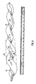
- Figures 1 to 3 show a woven stent 2 in the expanded condition.
- the stent has the usual wire strands 4 arranged in a mesh and collectively forming a mesh like outer wall 7. It is also provided with a helical portion or "stripe" 6 extending longitudinally and circumferentially of the stent.
- the helical portion 6 in this case consists of two additional strands 8 woven into the main mesh.
- One effect of the helical portion 6 is to create a cross-sectional shape approximating to a circle with a segment removed in the region corresponding to the helical portion, as seen in Figure 3 .
- This cross-sectional shape has a centroid 9.
- the locus of centroids 9 along the length of the stent defines a helical centre line 40, shown in Figure 1 .
- the centre line 40 follows a helical path about a longitudinal axis 30 which is at the centre of an imaginary cylindrical envelope 20 within which the stent is contained.
- the amplitude A of the helix is shown in Figure 1 .
- the amplitude A is greater than would be achieved by merely rotating the cross-sectional shape about the centre of the circle 3. In that case, the envelope 20 would simply correspond to the circle 3. However, the effect of the helical portion resisting extension during expansion is to cause the envelope 20 to be appreciably larger than the circle 3. This is another effect of the helical portion contributing to the creation of a non-planar or helical flow lumen.
- the stent In use, the stent is deployed at a target site and is then expanded by a balloon or by the elasticity or shape-memory properties of the strands 4.
- the helical portion 6 acts to restrict extension (at least in the longitudinal direction) and hence the expanded stent adopts the configuration described, in which the centre line of the stent follows a helical path.
- the outer wall 7 engages the fluid conduit wall and influences its shape so that the lumen of the fluid conduit at the target site also tends to have a helical centre line. This will help to promote swirl flow along the lumen.
- the handedness (“s" or "z”) of the stent will normally be chosen to complement the local fluid conduit geometry so as to enhance any swirl flow already existing upstream of the stent and not to cancel it.
- wires 8 In the example shown in Figures 1 to 3 two helically arranged wires 8 are provided, but other numbers of wires could be used.
- the wires could be designed to provide the greatest resistance to extension in the middle of the helical portion 6, with less resistance being provided towards the edges of the helical portion, for example by grading the wires with a thickest wire in the middle and thinner wires towards the edges. Such an arrangement could ensure that the shape of the expanded stent, when viewed,in transverse cross-section, does not have any sharp ridges or grooves and ideally corresponds closely to a circle.
- a helical portion is formed by a single helically arranged wire 8 to produce a stent of substantially circular cross-section.
- the single wire can provide resistance to longitudinal extension during expansion of the stent and cause it to define a lumen with a helical centre line.
- a circular cross-sectional shaped stent can still provide the desired swirl inducing effect providing the centre line of the lumen is helical.
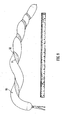
- Figures 4 and 5 show an example of a stent of the so-called helical spiral type.
- the basic stent design consists of a wire 10 in a wave form, shown at 12, with that wave form extending in the manner of a coil from one end of the stent to the other. Longitudinally adjacent waves of the wave form 12 are joined by connecting elements 14.
- the wavelength of the waves is, for most of the circumference of the stent, a distance D.
- this wavelength is reduced to less than D.
- the effect of the reduced wavelength is to cause the lumen of the fluid conduit in which the stent is expanded to adopt the desired configuration for promoting swirl flow in the lumen of the fluid conduit.
- the wavelength of the waves of the wave form 12 is reduced throughout the stent.
- the wavelength in the region of the helical portion 6 increases least.
- Extension in the circumferential direction is resisted by the helical portion 6. This could for example be achieved providing that the natural shape of the waves in the helical portion 6 is one having a smaller wavelength than D. This may be appropriate for example if the stent is made by being cut out from a metal sheet or tube.
- Another way of achieving the reduced circumferential expansion in the region of the helical portion 6 would be to provide short bridges 16 between circumferentially adjacent portions of the wave in the helical portion 6. Such a bridge 16 is shown in Figure 5 . Further bridges would be provided at intervals along the helical portion.
- Figure 7 shows a stent of the closed cell type with "v" hinges between adjacent cells.
- the helical portion 6 is provided by forming a helical line of cells 18 which are smaller than the other cells 20.
- the cells 20 expand to a predetermined size.
- the cells 18 expand to a smaller predetermined size and hence resist extension.
- the result is that the lumen of the fluid conduit in which the stent is expanded adopts a configuration promoting swirl flow.
- the various stents shown and described are provided with a single helical portion 6. However, other numbers of helical portions could be provided.
- the stents are non-rotationally symmetrical (rotational symmetry of order 1), as this can ensure that the centre line of the expanded stent follows a helical path.
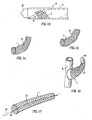
- Figure 14 shows an internal stent 12 for use in a graft vessel or an intact vessel.
- the stent 12 is fabricated from a linked wire mesh and has a helical form along substantially the whole length of the stent.
- the material used is preferably a shape memory alloy to facilitate insertion of the stent.
- Figure 15 shows an alternative internal stent 12, in which the linked wire mesh has a helical tubing portion 1 only over a short region at one end thereof.
- Figure 16 shows the stent 12 located in a graft 14 post insertion.
- the graft 14 surgically attached to an artery 6 has been shown transparent for purposes of illustration, to show the internally located, part helical wire mesh stent in-situ.
- a modification may involve providing the mesh with a smooth internal lining.
- an inner layer of the stent may be helically wound, without linkages, as described in WO 01/45593 .
- the helical form of the stents is arranged to promote swirl flow and thereby minimise flow instability and development of pathology.
- the stents shown in Figures 14 and 15 are defined within an envelope with a curved longitudinal axis. They are generally arch shaped. Such an arch may curve in a single plane or may itself be non-planar, in which case the non-planarity should promote swirl flow in the same direction as the helix.
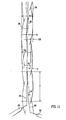
- the stents need not be arch shaped; they may instead have a generally straight axis, as shown for example in Figure 17 .
- the stent of Figure 17 has a straight central longitudinal axis 30, with a helical centre line 40 which undergoes about half of one turn.
- the low amplitude of the helix of the stent means that it is close to a cylindrical shape and can therefore be used in procedures where conventional stents would previously have been used. However, this is achieved without departing from a circular cross-sectional shape and without using helical ribs or other projecting formations. It is expected that the vessel into which the stent is inserted will be able to adopt the shape defined by the stent and therefore benefit from swirl flow.
- the helical centre line may undergo more than half of one turn, and indeed more than one or more turns.
- the stent of Figure 17 may be useful as an arterial stent where there is thrombosis or stenosis of for example coronary arteries.
- Figure 8 shows the result of an experiment carried out on a toy balloon 55.
- the balloon was of the elongated type. It was supported, without being inflated, on a cylindrical rod and a plastic strip 51 cut from another balloon was glued onto the outside of the supported balloon to form a longitudinally and circumferentially extending helical strip 6. A straight line 50 was drawn along the balloon. After the glue had set, the balloon was inflated and the inflated balloon is shown in Figure 8 .
- the inflated balloon 55 has a helical lumen. As with the stents, it has a helical centre line 40, which follows a helical path about a longitudinal axis 30. The longitudinal axis is at the centre of an imaginary cylindrical envelope 20 within which the balloon is contained. The amplitude A of the helix is shown in Figure 8 .
- the stents expand from the collapsed condition to the expanded condition without substantial twisting.
- the lack of twisting of the stent also enables it to have a plurality of turns without causing e.g. a blood vessel to twist during expansion, such twisting being undesirable because of the tethering of the blood vessel.
- the balloon of Figure 8 starts as a cylindrical membrane with a helical portion which is of greater (in this case double) wall thickness than the rest of the balloon. During inflation the thicker helical portion will tend to resist extension in all directions, including circumferential and longitudinal directions, thereby influencing the shape of the expanded balloon. Instead of adopting the normal cylindrical shape, the balloon forms a shape with a helical centre line 40.
- Figure 8 shows that the amplitude A achieved by the helical portion is much greater than would be achieved by simple rotation of a non-circular cross-section.
- the diameter of the envelope 20 is substantially greater than the diameter of the balloon. The same effect is obtained for an expanded stent outer wall or the wall of a balloon used in a balloon expandable stent.
- a plastic strip 52 was made with a tapered width, rather than with parallel side edges. It was found that the amplitude A of the helical centre line 40 was larger where the width of the strip was wider. This is shown in Figure 9 . A thinner strip tends to cause less deviation of the cross-sectional shape of the balloon from a circular shape.
- the shape of the expanded experimental balloon membranes may be considered as analogous to that of an expanded stent outer wall or the wall of a balloon used in a balloon expandable stent.
- a helical lumen is obtained, giving the desirable flow properties discussed above, without the use of ribs, vanes or other flow guides protruding into the flow.
- the experimental results thus show that by introducing a helical portion which resists extension during expansion of a stent, when expanded the stent will adopt a shape causing a fluid conduit which it supports to have a helical lumen, thereby promoting swirl flow.
- the effect observed in the balloons of Figures 8 and 9 may be obtained in a main stent body, either self-expanding or balloon expandable, and/or in a balloon which is used to expand a balloon expandable stent.
- Figure 10 shows a balloon expandable stent 2.
- a balloon 55 is provided with a helical strip 6.
- the balloon causes the stent 2 to adopt the desired helical geometry, expanding to a shape as shown in the experimental balloon of Figure 8 .
- the stent is designed to deform plastically so that it holds to the shape supporting a conduit e.g. blood vessel so as to have a helical flow lumen.
- the stent does not rely on the use of thicker wires which themselves provide ribs or flow guides in an otherwise circular cross-section lumen. Rather, the shape of the lumen is modified by the resistance of the helical portion to extension.
- the tubing portion 1 shown in Figure 11 has a circular cross-section, an external diameter D E , an internal diameter D I and a wall thickness T.
- the tubing is coiled into a helix of constant amplitude A (as measured from mean to extreme), constant pitch P, constant helix angle ⁇ and a swept width W.
- the tubing portion 1 is contained in an imaginary envelope 20 which extends longitudinally and has a width equal to the swept width W of the helix.
- the envelope 20 may be regarded as having a central longitudinal axis 30, which may also be referred to as an axis of helical rotation.
- the illustrated tubing portion 1 has a straight axis 30, but it will be appreciated that in alternative designs the central axis may be curved.
- the tubing portion has a centre line 40 which follows a helical path about the central longitudinal axis 30.
- the amplitude A is less than the tubing internal diameter D I .
- a R A D I
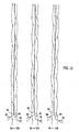
- Figure 11 shows the results of three experiments, at Reynolds numbers R E of 500, 250 and 100 respectively. It will be seen in all cases that the ink filaments 84 and 86 intertwine, indicating.that in the core there is swirl flow, i.e. flow which is generally rotating.
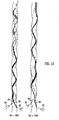
- Example 13 shows the results of two experiments with near-wall ink release, with Reynolds numbers R E of 500 and 250 respectively. It will be seen that in both cases the ink filaments follow the helical tubing geometry, indicating near-wall swirl. Furthermore, mixing of the ink filaments with the water is promoted.
- some embodiments of this invention are concerned with values of relative amplitude A R less than or equal to 0.5, i.e. small relative amplitudes.
- both the amplitude A and the relative amplitude A R equal zero, as there is no helix. Therefore, with values of relative amplitude A R approaching zero, the ability of the tubing portion to induce swirl will reduce.
- the lowest workable value of relative amplitude A R for any given situation will depend on the speed of flow and the viscosity and density of the fluid (i.e. Reynolds number) and on the pitch (helix angle) and the particular use of the tubing portion.
- Relative amplitudes of at least 0.05, 0.10, 0.15, 0.20, 0.25, 0.30, 0.35, 0.40 or 0.45 may be preferred.
Claims (7)
- Stent (2) pour insertion dans un conduit de fluide du corps humain ou animal lorsque le stent (2) se trouve à l'état affaissé pour assurer une expansion dans un état déployé, dans lequel, à l'état déployé, le stent a une ligne centrale (40) qui suit un trajet sensiblement hélicoïdal de façon à induire un écoulement tourbillonnant dans le conduit de fluide, caractérisé en ce que le pas et/ou l'amplitude de la ligne centrale hélicoïdale varie(nt) sur la longueur du stent de manière à introduire un écoulement tourbillonnant modéré à une extrémité amont du stent et à augmenter l'effet d'écoulement tourbillonnant dans la direction aval.
- Stent (2) selon la revendication 1, dans lequel l'angle d'hélice de la ligne centrale hélicoïdale varie jusqu'à un maximum de 65°.
- Stent (2) selon la revendication 1, dans lequel l'angle d'hélice de la ligne centrale hélicoïdale varie jusqu'à un maximum de 45°.
- Stent (2) selon la revendication 1, 2 ou 3, ayant un axe (30) autour duquel la ligne centrale (40) du stent suit un trajet sensiblement hélicoïdal, dans lequel ledit axe est droit.
- Stent (2) selon la revendication 1, 2 ou 3, ayant un axe (30) autour duquel la ligne centrale (40) du stent suit un trajet sensiblement hélicoïdal, dans lequel ledit axe est incurvé.
- Stent (2) selon la revendication 1, dans lequel l'amplitude relative (A) définie comme l'amplitude de l'hélice divisée par le diamètre interne du stent varie jusqu'à un maximum de 0,7.
- Stent (2) selon l'une quelconque des revendications précédentes, comprenant une paroi externe (7) susceptible de s'engager sur le conduit, la paroi externe ayant une partie hélicoïdale (6) qui, à l'état déployé, s'étend longitudinalement et sur la circonférence et qui, lors de l'expansion de l'état affaissé à l'état déployé, résiste à l'extension.
Priority Applications (1)
| Application Number | Priority Date | Filing Date | Title |
|---|---|---|---|
| EP10010780.4A EP2292183B1 (fr) | 2003-03-18 | 2004-03-18 | Ballonnet hélicoidale avec Extenseur |
Applications Claiming Priority (3)
| Application Number | Priority Date | Filing Date | Title |
|---|---|---|---|
| GBGB0306176.9A GB0306176D0 (en) | 2003-03-18 | 2003-03-18 | Tubing |
| GB0317003A GB0317003D0 (en) | 2003-07-21 | 2003-07-21 | Stent |
| EP04721558A EP1605867B1 (fr) | 2003-03-18 | 2004-03-18 | Prothese vasculaire helicoidale |
Related Parent Applications (2)
| Application Number | Title | Priority Date | Filing Date |
|---|---|---|---|
| EP04721558A Division EP1605867B1 (fr) | 2003-03-18 | 2004-03-18 | Prothese vasculaire helicoidale |
| EP04721558.7 Division | 2004-03-18 |
Related Child Applications (2)
| Application Number | Title | Priority Date | Filing Date |
|---|---|---|---|
| EP10010780.4A Division EP2292183B1 (fr) | 2003-03-18 | 2004-03-18 | Ballonnet hélicoidale avec Extenseur |
| EP10010780.4A Division-Into EP2292183B1 (fr) | 2003-03-18 | 2004-03-18 | Ballonnet hélicoidale avec Extenseur |
Publications (3)
| Publication Number | Publication Date |
|---|---|
| EP2145601A2 EP2145601A2 (fr) | 2010-01-20 |
| EP2145601A3 EP2145601A3 (fr) | 2010-04-14 |
| EP2145601B1 true EP2145601B1 (fr) | 2015-05-06 |
Family
ID=33031408
Family Applications (3)
| Application Number | Title | Priority Date | Filing Date |
|---|---|---|---|
| EP20090013197 Expired - Lifetime EP2145601B1 (fr) | 2003-03-18 | 2004-03-18 | Extenseur hélicoidale |
| EP04721558A Expired - Lifetime EP1605867B1 (fr) | 2003-03-18 | 2004-03-18 | Prothese vasculaire helicoidale |
| EP10010780.4A Expired - Lifetime EP2292183B1 (fr) | 2003-03-18 | 2004-03-18 | Ballonnet hélicoidale avec Extenseur |
Family Applications After (2)
| Application Number | Title | Priority Date | Filing Date |
|---|---|---|---|
| EP04721558A Expired - Lifetime EP1605867B1 (fr) | 2003-03-18 | 2004-03-18 | Prothese vasculaire helicoidale |
| EP10010780.4A Expired - Lifetime EP2292183B1 (fr) | 2003-03-18 | 2004-03-18 | Ballonnet hélicoidale avec Extenseur |
Country Status (9)
| Country | Link |
|---|---|
| US (2) | US8226704B2 (fr) |
| EP (3) | EP2145601B1 (fr) |
| JP (3) | JP4740118B2 (fr) |
| AT (1) | ATE446065T1 (fr) |
| AU (1) | AU2004222494A1 (fr) |
| BR (1) | BRPI0408418A (fr) |
| CA (1) | CA2519437A1 (fr) |
| DE (1) | DE602004023700D1 (fr) |
| WO (1) | WO2004082533A1 (fr) |
Families Citing this family (69)
| Publication number | Priority date | Publication date | Assignee | Title |
|---|---|---|---|---|
| GB2344053A (en) * | 1998-11-30 | 2000-05-31 | Imperial College | Stents for blood vessels |
| GB9828696D0 (en) | 1998-12-29 | 1999-02-17 | Houston J G | Blood-flow tubing |
| GB0306176D0 (en) | 2003-03-18 | 2003-04-23 | Imp College Innovations Ltd | Tubing |
| BRPI0408418A (pt) | 2003-03-18 | 2006-03-21 | Veryan Medical Ltd | stent |
| EP1682210A4 (fr) | 2003-11-07 | 2009-11-04 | Merlin Md Pte Ltd | Dispositifs medicaux implantables a visibilite, proprietes mecaniques et biocompatibilite ameliorees |
| GB0402736D0 (en) * | 2004-02-06 | 2004-03-10 | Tayside Flow Technologies Ltd | A drug delivery device |
| SG133420A1 (en) * | 2005-12-13 | 2007-07-30 | Merlin Md Pte Ltd | An endovascular device with membrane having permanently attached agents |
| US8915952B2 (en) | 2004-03-31 | 2014-12-23 | Merlin Md Pte Ltd. | Method for treating aneurysms |
| US8500751B2 (en) | 2004-03-31 | 2013-08-06 | Merlin Md Pte Ltd | Medical device |
| US8715340B2 (en) | 2004-03-31 | 2014-05-06 | Merlin Md Pte Ltd. | Endovascular device with membrane |
| US8808354B2 (en) | 2004-09-22 | 2014-08-19 | Veryan Medical Limited | Helical stent |
| GB2418362C (en) * | 2004-09-22 | 2010-05-05 | Veryan Medical Ltd | Stent |
| GB2425485A (en) * | 2005-04-29 | 2006-11-01 | Veryan Medical Ltd | Shape memory stent producing non planar, swirling flow |
| AU2008251804B2 (en) * | 2007-05-11 | 2013-01-10 | Cook Incorporated | Stent grafts for the thoracic aorta |
| US10245165B2 (en) * | 2009-04-02 | 2019-04-02 | Q3 Medical Devices Limited | Stent |
| US8231686B2 (en) * | 2008-06-11 | 2012-07-31 | Eric Mangiardi | Stent |
| US11207199B2 (en) * | 2008-06-11 | 2021-12-28 | Q3 Medical Devices Limited | Stent with anti-migration devices |
| US20100256731A1 (en) * | 2009-04-02 | 2010-10-07 | Mangiardi Eric K | Stent |
| EP2301486B1 (fr) * | 2008-06-27 | 2014-12-24 | Kabushiki Kaisha Kyoto Iryo Sekkei | Stent vasculaire |
| US8262692B2 (en) | 2008-09-05 | 2012-09-11 | Merlin Md Pte Ltd | Endovascular device |
| JP2012502746A (ja) * | 2008-09-16 | 2012-02-02 | シー.アール.バード,インコーポレイテッド | ステント |
| US20140135900A9 (en) | 2008-10-10 | 2014-05-15 | Kevin Heraty | Medical device suitable for location in a body lumen |
| US9149377B2 (en) | 2008-10-10 | 2015-10-06 | Veryan Medical Ltd. | Stent suitable for deployment in a blood vessel |
| JP2012505004A (ja) * | 2008-10-10 | 2012-03-01 | ヴェリヤン・メディカル・リミテッド | 血管内展開形態に適するステント |
| WO2010041038A1 (fr) * | 2008-10-10 | 2010-04-15 | Veryan Medical Limited | Dispositif médical |
| US9539120B2 (en) * | 2008-10-10 | 2017-01-10 | Veryan Medical Ltd. | Medical device suitable for location in a body lumen |
| US9597214B2 (en) | 2008-10-10 | 2017-03-21 | Kevin Heraty | Medical device |
| WO2010128311A1 (fr) * | 2009-05-08 | 2010-11-11 | Veryan Medical Limited | Dispositif médical pouvant être implanté dans une lumière de l'organisme |
| US10456276B2 (en) | 2009-05-08 | 2019-10-29 | Veryan Medical Limited | Medical device suitable for location in a body lumen |
| US8936634B2 (en) * | 2009-07-15 | 2015-01-20 | W. L. Gore & Associates, Inc. | Self constraining radially expandable medical devices |
| GB2475338A (en) | 2009-11-17 | 2011-05-18 | Tayside Flow Technologies Ltd | A tubular conduit with an internal and external helical formation |
| WO2011081814A1 (fr) * | 2009-12-28 | 2011-07-07 | Cook Medical Technologies Llc | Dispositif endoluminal comportant des régions résistant à la torsion |
| US8353952B2 (en) * | 2010-04-07 | 2013-01-15 | Medtronic Vascular, Inc. | Stent with therapeutic substance |
| WO2012002944A1 (fr) | 2010-06-29 | 2012-01-05 | Artventive Medical Group, Inc. | Réduction d'un écoulement à travers une structure tubulaire |
| US9247942B2 (en) | 2010-06-29 | 2016-02-02 | Artventive Medical Group, Inc. | Reversible tubal contraceptive device |
| US9149277B2 (en) | 2010-10-18 | 2015-10-06 | Artventive Medical Group, Inc. | Expandable device delivery |
| ES2943709T3 (es) | 2012-04-06 | 2023-06-15 | Merlin Md Pte Ltd | Dispositivos para tratar un aneurisma |
| US9095344B2 (en) | 2013-02-05 | 2015-08-04 | Artventive Medical Group, Inc. | Methods and apparatuses for blood vessel occlusion |
| US8984733B2 (en) | 2013-02-05 | 2015-03-24 | Artventive Medical Group, Inc. | Bodily lumen occlusion |
| WO2014140642A1 (fr) | 2013-03-15 | 2014-09-18 | Veryan Medical Limited | Appareil d'endoprothèse et procédés de traitement |
| JP6001163B2 (ja) * | 2013-04-01 | 2016-10-05 | テルモ株式会社 | シース |
| EP2991565B1 (fr) | 2013-05-02 | 2019-06-26 | Veryan Medical Limited | Ballonnet extensible |
| US10149968B2 (en) | 2013-06-14 | 2018-12-11 | Artventive Medical Group, Inc. | Catheter-assisted tumor treatment |
| US9737308B2 (en) | 2013-06-14 | 2017-08-22 | Artventive Medical Group, Inc. | Catheter-assisted tumor treatment |
| US9636116B2 (en) | 2013-06-14 | 2017-05-02 | Artventive Medical Group, Inc. | Implantable luminal devices |
| US9737306B2 (en) | 2013-06-14 | 2017-08-22 | Artventive Medical Group, Inc. | Implantable luminal devices |
| US10363043B2 (en) | 2014-05-01 | 2019-07-30 | Artventive Medical Group, Inc. | Treatment of incompetent vessels |
| KR101628711B1 (ko) * | 2014-06-26 | 2016-06-09 | 주식회사 에스앤지바이오텍 | 외부유로가 형성된 스텐트 |
| EP4302726A3 (fr) | 2014-10-09 | 2024-03-27 | Boston Scientific Scimed, Inc. | Mandrin et procédé de formation d'une structure de stent extensible |
| GB2538072B (en) * | 2015-05-05 | 2017-11-15 | Strait Access Tech Holdings (Pty) Ltd | A non-occlusive dilation and deployment catheter device |
| GB201508593D0 (en) * | 2015-05-19 | 2015-07-01 | Vascular Flow Technologies Ltd | A stent |
| US10813644B2 (en) | 2016-04-01 | 2020-10-27 | Artventive Medical Group, Inc. | Occlusive implant and delivery system |
| JP6955679B2 (ja) * | 2016-07-07 | 2021-10-27 | ニプロ株式会社 | ステント |
| US10492937B2 (en) | 2016-10-17 | 2019-12-03 | Cook Medical Technologies Llc | Deploying a balloon expandable stent to induce spiral flow |
| CA3039285A1 (fr) | 2016-10-25 | 2018-05-03 | Magenta Medical Ltd. | Dispositif d'assistance ventriculaire |
| CA3046087A1 (fr) | 2016-12-09 | 2018-06-14 | Zenflow, Inc. | Systemes, dispositifs et methodes pour le deploiement precis d'un implant dans l'uretre prostatique |
| US10905861B2 (en) | 2017-04-25 | 2021-02-02 | Project Moray, Inc. | Matrix supported balloon articulation systems, devices, and methods for catheters and other uses |
| EP3854443A1 (fr) | 2018-01-10 | 2021-07-28 | Magenta Medical Ltd. | Dispositif d'assistance ventriculaire |
| US10905808B2 (en) | 2018-01-10 | 2021-02-02 | Magenta Medical Ltd. | Drive cable for use with a blood pump |
| US11154410B2 (en) | 2018-06-29 | 2021-10-26 | Monarch Biosciences, Inc. | Spiral-based thin-film mesh systems and related methods |
| JP7293594B2 (ja) * | 2018-09-21 | 2023-06-20 | 日本ゼオン株式会社 | 消化管ステント |
| JP7348292B2 (ja) | 2019-01-07 | 2023-09-20 | ボストン サイエンティフィック サイムド,インコーポレイテッド | 移動防止機構付ステント |
| WO2020152611A2 (fr) | 2019-01-24 | 2020-07-30 | Magenta Medical Ltd | Dispositif d'assistance ventriculaire |
| CN110251272A (zh) * | 2019-06-13 | 2019-09-20 | 杜伟远 | 一种骨架式立体贴附心血管内支撑装置 |
| AU2020387396A1 (en) | 2019-11-19 | 2022-04-21 | Zenflow, Inc. | Systems, devices, and methods for the accurate deployment and imaging of an implant in the prostatic urethra |
| GB2598271B (en) * | 2020-02-18 | 2024-03-06 | Wai Yin Lau Ernest | A scaffold for a tube |
| AU2021390484A1 (en) | 2020-12-02 | 2023-06-22 | Boston Scientific Scimed, Inc. | Stent with improved deployment characteristics |
| CN115844605B (zh) * | 2023-02-17 | 2023-05-16 | 太原理工大学 | 一种动脉血管支架 |
| CN117481650B (zh) * | 2024-01-02 | 2024-03-19 | 德州市红拳医疗器械有限公司 | 一种动物采血器 |
Family Cites Families (69)
| Publication number | Priority date | Publication date | Assignee | Title |
|---|---|---|---|---|
| FR2248015A1 (en) | 1973-10-17 | 1975-05-16 | Rhone Poulenc Ind | Artificial ureter or urethra - watertight flexible tube has helical rib in outside wall to prevent creasing |
| US4604762A (en) | 1981-02-13 | 1986-08-12 | Thoratec Laboratories Corporation | Arterial graft prosthesis |
| US4596548A (en) | 1985-03-25 | 1986-06-24 | Dlp Inc. | Single stage venous catheter |
| US4762130A (en) | 1987-01-15 | 1988-08-09 | Thomas J. Fogarty | Catheter with corkscrew-like balloon |
| KR920006734Y1 (ko) | 1990-02-07 | 1992-09-26 | 이종호 | 내경면에 나선상의 유체 삼각 안내돌기를 갖는 다층 파이프 |
| US5156619A (en) | 1990-06-15 | 1992-10-20 | Ehrenfeld William K | Flanged end-to-side vascular graft |
| FR2666502B1 (fr) | 1990-09-10 | 1993-09-24 | Roux Daniel | Greffon vasculaire synthetique. |
| US5282847A (en) | 1991-02-28 | 1994-02-01 | Medtronic, Inc. | Prosthetic vascular grafts with a pleated structure |
| US5181911A (en) | 1991-04-22 | 1993-01-26 | Shturman Technologies, Inc. | Helical balloon perfusion angioplasty catheter |
| US5507767A (en) * | 1992-01-15 | 1996-04-16 | Cook Incorporated | Spiral stent |
| US5295959A (en) | 1992-03-13 | 1994-03-22 | Medtronic, Inc. | Autoperfusion dilatation catheter having a bonded channel |
| DK0625917T3 (da) * | 1992-12-15 | 1998-09-28 | Sanofi Sa | Indretning til præparation af en opløsning, en suspension eller en emulsion af en medicinsk substans |
| US5370691A (en) * | 1993-01-26 | 1994-12-06 | Target Therapeutics, Inc. | Intravascular inflatable stent |
| US5354288A (en) | 1993-02-24 | 1994-10-11 | Minnesota Mining And Manufacturing Company | Low velocity aortic cannula |
| US5308356A (en) * | 1993-02-25 | 1994-05-03 | Blackshear Jr Perry L | Passive perfusion angioplasty catheter |
| US5383856A (en) | 1993-03-19 | 1995-01-24 | Bersin; Robert M. | Helical spiral balloon catheter |
| US5441515A (en) | 1993-04-23 | 1995-08-15 | Advanced Cardiovascular Systems, Inc. | Ratcheting stent |
| AU6787194A (en) | 1993-05-11 | 1994-12-12 | Target Therapeutics, Inc. | Temporary inflatable intravascular prosthesis |
| US6039754A (en) | 1993-10-01 | 2000-03-21 | Imperial College Of Science Technology & Medicine | Vascular prostheses |
| US5545132A (en) | 1993-12-21 | 1996-08-13 | C. R. Bard, Inc. | Helically grooved balloon for dilatation catheter and method of using |
| US5484411A (en) * | 1994-01-14 | 1996-01-16 | Cordis Corporation | Spiral shaped perfusion balloon and method of use and manufacture |
| AU1128495A (en) | 1994-06-17 | 1996-01-15 | W.L. Gore & Associates, Inc. | Protective surgical sheath for coronary artery bypass grafts |
| CA2147547C (fr) | 1994-08-02 | 2006-12-19 | Peter J. Schmitt | Greffon souple tisse mince |
| WO1996011720A1 (fr) * | 1994-10-17 | 1996-04-25 | Kabushikikaisha Igaki Iryo Sekkei | Extenseur endovasculaire liberant un medicament |
| EP0714640A1 (fr) | 1994-11-28 | 1996-06-05 | Advanced Cardiovascular Systems, Inc. | Système et méthode pour introduire plusieurs stents |
| US5749851A (en) | 1995-03-02 | 1998-05-12 | Scimed Life Systems, Inc. | Stent installation method using balloon catheter having stepped compliance curve |
| GB2298577B (en) | 1995-03-09 | 1999-02-17 | Univ Bristol | Arteriovenous bypass grafting |
| US6053943A (en) * | 1995-12-08 | 2000-04-25 | Impra, Inc. | Endoluminal graft with integral structural support and method for making same |
| JPH08257139A (ja) | 1995-03-28 | 1996-10-08 | Nippon Zeon Co Ltd | バルーンカテーテル |
| US5709713A (en) * | 1995-03-31 | 1998-01-20 | Cardiovascular Concepts, Inc. | Radially expansible vascular prosthesis having reversible and other locking structures |
| US5766201A (en) | 1995-06-07 | 1998-06-16 | Boston Scientific Corporation | Expandable catheter |
| US5865723A (en) | 1995-12-29 | 1999-02-02 | Ramus Medical Technologies | Method and apparatus for forming vascular prostheses |
| US5800514A (en) * | 1996-05-24 | 1998-09-01 | Meadox Medicals, Inc. | Shaped woven tubular soft-tissue prostheses and methods of manufacturing |
| US5735816A (en) | 1996-07-23 | 1998-04-07 | Medtronic, Inc. | Spiral sheath retainer for autoperfusion dilatation catheter balloon |
| EP2298241A3 (fr) | 1996-12-03 | 2011-11-02 | Atrium Medical Corporation | Prothèse à plusieurs étages |
| GB9710905D0 (en) | 1997-05-27 | 1997-07-23 | Imperial College | Stent for blood vessel |
| IL121882A0 (en) * | 1997-10-05 | 1998-03-10 | Voinov Valerian | Expandable stent with bioabsorbable local drug delivery and technology for its manufacture |
| US20020019660A1 (en) | 1998-09-05 | 2002-02-14 | Marc Gianotti | Methods and apparatus for a curved stent |
| GB2344053A (en) | 1998-11-30 | 2000-05-31 | Imperial College | Stents for blood vessels |
| GB9828696D0 (en) * | 1998-12-29 | 1999-02-17 | Houston J G | Blood-flow tubing |
| AU758027B2 (en) | 1999-02-26 | 2003-03-13 | Lemaitre Vascular, Inc. | Catheter assembly with endoluminal prosthesis and method for placing |
| US6325825B1 (en) | 1999-04-08 | 2001-12-04 | Cordis Corporation | Stent with variable wall thickness |
| US6997951B2 (en) | 1999-06-30 | 2006-02-14 | Edwards Lifesciences Ag | Method and device for treatment of mitral insufficiency |
| US6364904B1 (en) * | 1999-07-02 | 2002-04-02 | Scimed Life Systems, Inc. | Helically formed stent/graft assembly |
| US6375660B1 (en) * | 1999-11-22 | 2002-04-23 | Cordis Corporation | Stent delivery system with a fixed guide wire |
| ATE284183T1 (de) | 1999-12-21 | 2004-12-15 | Imperial College | Vaskuläre stents |
| EP1127557A1 (fr) | 2000-02-25 | 2001-08-29 | EndoArt S.A. | Greffe vasculaire |
| JP2001252987A (ja) | 2000-03-13 | 2001-09-18 | Jiro Fukuda | スパイラルバルーン |
| DE10012460A1 (de) | 2000-03-15 | 2001-09-20 | Biotronik Mess & Therapieg | Stent |
| ES2369784T3 (es) | 2000-05-19 | 2011-12-05 | Advanced Bio Prosthetic Surfaces, Ltd. | Métodos y aparatos para la fabricación de un extensor intravascular. |
| ATE519454T1 (de) * | 2000-05-22 | 2011-08-15 | Orbusneich Medical Inc | Selbstexpandierbarer stent |
| US6554848B2 (en) | 2000-06-02 | 2003-04-29 | Advanced Cardiovascular Systems, Inc. | Marker device for rotationally orienting a stent delivery system prior to deploying a curved self-expanding stent |
| US6569191B1 (en) * | 2000-07-27 | 2003-05-27 | Bionx Implants, Inc. | Self-expanding stent with enhanced radial expansion and shape memory |
| EP1179322A3 (fr) | 2000-08-09 | 2004-02-25 | BIOTRONIK Mess- und Therapiegeräte GmbH & Co Ingenieurbüro Berlin | Procédé et dispositif de sertissage de prothèses endovasculaires |
| DE10044043A1 (de) | 2000-08-30 | 2002-03-14 | Biotronik Mess & Therapieg | Reponierbarer Stent |
| US6527739B1 (en) | 2000-12-29 | 2003-03-04 | Advanced Cardiovascular Systems, Inc. | Spiraled balloon arrangement for treatment of a tortuous vessel |
| WO2002066096A2 (fr) | 2001-02-16 | 2002-08-29 | Cordis Corporation | Systeme de pose d'endoprothese a sonde a ballonnet comportant des cretes |
| NL1018881C2 (nl) * | 2001-05-08 | 2002-11-25 | Blue Medical Devices B V | Ballonkatheter met stent en werkwijze voor het vervaardigen daarvan. |
| GB2379996B (en) | 2001-06-05 | 2004-05-19 | Tayside Flow Technologies Ltd | Flow means |
| US20020198589A1 (en) | 2001-06-22 | 2002-12-26 | Leong Veronica Jade | Tessellated stent and method of manufacture |
| GB2369797B (en) | 2001-11-20 | 2002-11-06 | Tayside Flow Technologies Ltd | Helical formations in tubes |
| EP1509169B1 (fr) | 2002-06-05 | 2012-10-10 | Vascular Flow Technologies Limited | Procede pour determiner l'angle d'helice d'une formation helicoidale dans un conduit |
| CA2411220C (fr) * | 2002-06-28 | 2010-11-16 | Lubomyr M. Cymbalisty | Melangeur fixe a ecoulement hydrodynamique et methode d'utilisation connexe pour separer des sables bitumineux et des matieres de nature semblable |
| GB0227369D0 (en) | 2002-11-23 | 2002-12-31 | Tayside Flow Technologies Ltd | A helical formation for a conduit |
| US7686824B2 (en) | 2003-01-21 | 2010-03-30 | Angioscore, Inc. | Apparatus and methods for treating hardened vascular lesions |
| BRPI0408418A (pt) | 2003-03-18 | 2006-03-21 | Veryan Medical Ltd | stent |
| GB2425485A (en) | 2005-04-29 | 2006-11-01 | Veryan Medical Ltd | Shape memory stent producing non planar, swirling flow |
| US8192477B2 (en) | 2005-11-14 | 2012-06-05 | Boston Scientific Scimed, Inc. | Twisting bifurcation delivery system |
| CN101743032B (zh) | 2007-03-27 | 2012-09-19 | 因特拉泰克医药有限公司 | 螺旋囊体导管 |
-
2004
- 2004-03-18 BR BRPI0408418-7A patent/BRPI0408418A/pt not_active IP Right Cessation
- 2004-03-18 JP JP2006505978A patent/JP4740118B2/ja not_active Expired - Lifetime
- 2004-03-18 EP EP20090013197 patent/EP2145601B1/fr not_active Expired - Lifetime
- 2004-03-18 US US10/549,355 patent/US8226704B2/en active Active
- 2004-03-18 AU AU2004222494A patent/AU2004222494A1/en not_active Abandoned
- 2004-03-18 CA CA002519437A patent/CA2519437A1/fr not_active Abandoned
- 2004-03-18 EP EP04721558A patent/EP1605867B1/fr not_active Expired - Lifetime
- 2004-03-18 AT AT04721558T patent/ATE446065T1/de not_active IP Right Cessation
- 2004-03-18 EP EP10010780.4A patent/EP2292183B1/fr not_active Expired - Lifetime
- 2004-03-18 WO PCT/GB2004/001155 patent/WO2004082533A1/fr active Application Filing
- 2004-03-18 DE DE602004023700T patent/DE602004023700D1/de not_active Expired - Lifetime
-
2009
- 2009-03-03 US US12/397,147 patent/US8784476B2/en active Active
-
2010
- 2010-02-02 JP JP2010021334A patent/JP5328046B2/ja not_active Expired - Lifetime
- 2010-02-02 JP JP2010021333A patent/JP5108906B2/ja not_active Expired - Lifetime
Also Published As
| Publication number | Publication date |
|---|---|
| JP2010142659A (ja) | 2010-07-01 |
| EP1605867A1 (fr) | 2005-12-21 |
| EP2292183A1 (fr) | 2011-03-09 |
| JP5328046B2 (ja) | 2013-10-30 |
| JP5108906B2 (ja) | 2012-12-26 |
| CA2519437A1 (fr) | 2004-09-30 |
| EP2145601A2 (fr) | 2010-01-20 |
| JP4740118B2 (ja) | 2011-08-03 |
| EP1605867B1 (fr) | 2009-10-21 |
| EP2145601A3 (fr) | 2010-04-14 |
| ATE446065T1 (de) | 2009-11-15 |
| EP2292183B1 (fr) | 2017-10-25 |
| JP2010142660A (ja) | 2010-07-01 |
| JP2006520630A (ja) | 2006-09-14 |
| US8226704B2 (en) | 2012-07-24 |
| US8784476B2 (en) | 2014-07-22 |
| AU2004222494A1 (en) | 2004-09-30 |
| WO2004082533A1 (fr) | 2004-09-30 |
| US20090276029A1 (en) | 2009-11-05 |
| US20060265051A1 (en) | 2006-11-23 |
| DE602004023700D1 (de) | 2009-12-03 |
| BRPI0408418A (pt) | 2006-03-21 |
| WO2004082533A8 (fr) | 2005-02-24 |
Similar Documents
| Publication | Publication Date | Title |
|---|---|---|
| EP2145601B1 (fr) | Extenseur hélicoidale | |
| EP1799152B1 (fr) | Endoprothese vasculaire | |
| US8808354B2 (en) | Helical stent | |
| US7316711B2 (en) | Intralumenal stent device for use in body lumens of various diameters | |
| JP6180475B2 (ja) | 可撓性ステント設計 | |
| ZA200507489B (en) | Helical stent | |
| US20100004728A1 (en) | Graft endoframe having axially variable characteristics | |
| US20020133222A1 (en) | Expandable stent having a plurality of interconnected expansion modules | |
| KR20140129043A (ko) | 자가 팽창형 스텐트 | |
| EP1605868B1 (fr) | Prothese vasculaire helicoidale |
Legal Events
| Date | Code | Title | Description |
|---|---|---|---|
| PUAI | Public reference made under article 153(3) epc to a published international application that has entered the european phase |
Free format text: ORIGINAL CODE: 0009012 |
|
| AC | Divisional application: reference to earlier application |
Ref document number: 1605867 Country of ref document: EP Kind code of ref document: P |
|
| AK | Designated contracting states |
Kind code of ref document: A2 Designated state(s): AT BE BG CH CY CZ DE DK EE ES FI FR GB GR HU IE IT LI LU MC NL PL PT RO SE SI SK TR |
|
| PUAL | Search report despatched |
Free format text: ORIGINAL CODE: 0009013 |
|
| AK | Designated contracting states |
Kind code of ref document: A3 Designated state(s): AT BE BG CH CY CZ DE DK EE ES FI FR GB GR HU IE IT LI LU MC NL PL PT RO SE SI SK TR |
|
| 17P | Request for examination filed |
Effective date: 20101001 |
|
| 17Q | First examination report despatched |
Effective date: 20101110 |
|
| REG | Reference to a national code |
Ref country code: DE Ref legal event code: R079 Ref document number: 602004047155 Country of ref document: DE Free format text: PREVIOUS MAIN CLASS: A61F0002060000 Ipc: A61F0002860000 |
|
| RIC1 | Information provided on ipc code assigned before grant |
Ipc: A61F 2/86 20130101AFI20140523BHEP |
|
| GRAP | Despatch of communication of intention to grant a patent |
Free format text: ORIGINAL CODE: EPIDOSNIGR1 |
|
| INTG | Intention to grant announced |
Effective date: 20150105 |
|
| GRAS | Grant fee paid |
Free format text: ORIGINAL CODE: EPIDOSNIGR3 |
|
| GRAA | (expected) grant |
Free format text: ORIGINAL CODE: 0009210 |
|
| RIN1 | Information on inventor provided before grant (corrected) |
Inventor name: WATKINS, NICHOLAS V. Inventor name: BIRCH, PHILIP L. Inventor name: CARO, COLIN G. Inventor name: FALZON, BRIAN G. |
|
| AC | Divisional application: reference to earlier application |
Ref document number: 1605867 Country of ref document: EP Kind code of ref document: P |
|
| AK | Designated contracting states |
Kind code of ref document: B1 Designated state(s): AT BE BG CH CY CZ DE DK EE ES FI FR GB GR HU IE IT LI LU MC NL PL PT RO SE SI SK TR |
|
| REG | Reference to a national code |
Ref country code: GB Ref legal event code: FG4D |
|
| REG | Reference to a national code |
Ref country code: CH Ref legal event code: EP |
|
| REG | Reference to a national code |
Ref country code: IE Ref legal event code: FG4D |
|
| REG | Reference to a national code |
Ref country code: AT Ref legal event code: REF Ref document number: 725167 Country of ref document: AT Kind code of ref document: T Effective date: 20150615 |
|
| REG | Reference to a national code |
Ref country code: NL Ref legal event code: T3 |
|
| REG | Reference to a national code |
Ref country code: DE Ref legal event code: R096 Ref document number: 602004047155 Country of ref document: DE Effective date: 20150618 |
|
| REG | Reference to a national code |
Ref country code: AT Ref legal event code: MK05 Ref document number: 725167 Country of ref document: AT Kind code of ref document: T Effective date: 20150506 |
|
| PG25 | Lapsed in a contracting state [announced via postgrant information from national office to epo] |
Ref country code: PT Free format text: LAPSE BECAUSE OF FAILURE TO SUBMIT A TRANSLATION OF THE DESCRIPTION OR TO PAY THE FEE WITHIN THE PRESCRIBED TIME-LIMIT Effective date: 20150907 Ref country code: ES Free format text: LAPSE BECAUSE OF FAILURE TO SUBMIT A TRANSLATION OF THE DESCRIPTION OR TO PAY THE FEE WITHIN THE PRESCRIBED TIME-LIMIT Effective date: 20150506 Ref country code: FI Free format text: LAPSE BECAUSE OF FAILURE TO SUBMIT A TRANSLATION OF THE DESCRIPTION OR TO PAY THE FEE WITHIN THE PRESCRIBED TIME-LIMIT Effective date: 20150506 |
|
| PG25 | Lapsed in a contracting state [announced via postgrant information from national office to epo] |
Ref country code: AT Free format text: LAPSE BECAUSE OF FAILURE TO SUBMIT A TRANSLATION OF THE DESCRIPTION OR TO PAY THE FEE WITHIN THE PRESCRIBED TIME-LIMIT Effective date: 20150506 Ref country code: BG Free format text: LAPSE BECAUSE OF FAILURE TO SUBMIT A TRANSLATION OF THE DESCRIPTION OR TO PAY THE FEE WITHIN THE PRESCRIBED TIME-LIMIT Effective date: 20150806 Ref country code: GR Free format text: LAPSE BECAUSE OF FAILURE TO SUBMIT A TRANSLATION OF THE DESCRIPTION OR TO PAY THE FEE WITHIN THE PRESCRIBED TIME-LIMIT Effective date: 20150807 |
|
| PG25 | Lapsed in a contracting state [announced via postgrant information from national office to epo] |
Ref country code: DK Free format text: LAPSE BECAUSE OF FAILURE TO SUBMIT A TRANSLATION OF THE DESCRIPTION OR TO PAY THE FEE WITHIN THE PRESCRIBED TIME-LIMIT Effective date: 20150506 Ref country code: EE Free format text: LAPSE BECAUSE OF FAILURE TO SUBMIT A TRANSLATION OF THE DESCRIPTION OR TO PAY THE FEE WITHIN THE PRESCRIBED TIME-LIMIT Effective date: 20150506 |
|
| REG | Reference to a national code |
Ref country code: DE Ref legal event code: R097 Ref document number: 602004047155 Country of ref document: DE |
|
| PG25 | Lapsed in a contracting state [announced via postgrant information from national office to epo] |
Ref country code: CZ Free format text: LAPSE BECAUSE OF FAILURE TO SUBMIT A TRANSLATION OF THE DESCRIPTION OR TO PAY THE FEE WITHIN THE PRESCRIBED TIME-LIMIT Effective date: 20150506 Ref country code: RO Free format text: LAPSE BECAUSE OF NON-PAYMENT OF DUE FEES Effective date: 20150506 Ref country code: SK Free format text: LAPSE BECAUSE OF FAILURE TO SUBMIT A TRANSLATION OF THE DESCRIPTION OR TO PAY THE FEE WITHIN THE PRESCRIBED TIME-LIMIT Effective date: 20150506 Ref country code: PL Free format text: LAPSE BECAUSE OF FAILURE TO SUBMIT A TRANSLATION OF THE DESCRIPTION OR TO PAY THE FEE WITHIN THE PRESCRIBED TIME-LIMIT Effective date: 20150506 |
|
| PLBE | No opposition filed within time limit |
Free format text: ORIGINAL CODE: 0009261 |
|
| STAA | Information on the status of an ep patent application or granted ep patent |
Free format text: STATUS: NO OPPOSITION FILED WITHIN TIME LIMIT |
|
| REG | Reference to a national code |
Ref country code: FR Ref legal event code: PLFP Year of fee payment: 13 |
|
| 26N | No opposition filed |
Effective date: 20160209 |
|
| PG25 | Lapsed in a contracting state [announced via postgrant information from national office to epo] |
Ref country code: SI Free format text: LAPSE BECAUSE OF FAILURE TO SUBMIT A TRANSLATION OF THE DESCRIPTION OR TO PAY THE FEE WITHIN THE PRESCRIBED TIME-LIMIT Effective date: 20150506 |
|
| PG25 | Lapsed in a contracting state [announced via postgrant information from national office to epo] |
Ref country code: BE Free format text: LAPSE BECAUSE OF FAILURE TO SUBMIT A TRANSLATION OF THE DESCRIPTION OR TO PAY THE FEE WITHIN THE PRESCRIBED TIME-LIMIT Effective date: 20150506 |
|
| PG25 | Lapsed in a contracting state [announced via postgrant information from national office to epo] |
Ref country code: MC Free format text: LAPSE BECAUSE OF FAILURE TO SUBMIT A TRANSLATION OF THE DESCRIPTION OR TO PAY THE FEE WITHIN THE PRESCRIBED TIME-LIMIT Effective date: 20150506 Ref country code: LU Free format text: LAPSE BECAUSE OF FAILURE TO SUBMIT A TRANSLATION OF THE DESCRIPTION OR TO PAY THE FEE WITHIN THE PRESCRIBED TIME-LIMIT Effective date: 20160318 |
|
| REG | Reference to a national code |
Ref country code: CH Ref legal event code: PL |
|
| PG25 | Lapsed in a contracting state [announced via postgrant information from national office to epo] |
Ref country code: CH Free format text: LAPSE BECAUSE OF NON-PAYMENT OF DUE FEES Effective date: 20160331 Ref country code: LI Free format text: LAPSE BECAUSE OF NON-PAYMENT OF DUE FEES Effective date: 20160331 |
|
| REG | Reference to a national code |
Ref country code: FR Ref legal event code: PLFP Year of fee payment: 14 |
|
| PG25 | Lapsed in a contracting state [announced via postgrant information from national office to epo] |
Ref country code: SE Free format text: LAPSE BECAUSE OF FAILURE TO SUBMIT A TRANSLATION OF THE DESCRIPTION OR TO PAY THE FEE WITHIN THE PRESCRIBED TIME-LIMIT Effective date: 20150506 |
|
| REG | Reference to a national code |
Ref country code: FR Ref legal event code: PLFP Year of fee payment: 15 |
|
| PG25 | Lapsed in a contracting state [announced via postgrant information from national office to epo] |
Ref country code: CY Free format text: LAPSE BECAUSE OF FAILURE TO SUBMIT A TRANSLATION OF THE DESCRIPTION OR TO PAY THE FEE WITHIN THE PRESCRIBED TIME-LIMIT Effective date: 20150506 Ref country code: HU Free format text: LAPSE BECAUSE OF FAILURE TO SUBMIT A TRANSLATION OF THE DESCRIPTION OR TO PAY THE FEE WITHIN THE PRESCRIBED TIME-LIMIT; INVALID AB INITIO Effective date: 20040318 |
|
| PG25 | Lapsed in a contracting state [announced via postgrant information from national office to epo] |
Ref country code: TR Free format text: LAPSE BECAUSE OF FAILURE TO SUBMIT A TRANSLATION OF THE DESCRIPTION OR TO PAY THE FEE WITHIN THE PRESCRIBED TIME-LIMIT Effective date: 20150506 |
|
| REG | Reference to a national code |
Ref country code: DE Ref legal event code: R082 Ref document number: 602004047155 Country of ref document: DE |
|
| PGFP | Annual fee paid to national office [announced via postgrant information from national office to epo] |
Ref country code: IE Payment date: 20230323 Year of fee payment: 20 Ref country code: FR Payment date: 20230317 Year of fee payment: 20 |
|
| PGFP | Annual fee paid to national office [announced via postgrant information from national office to epo] |
Ref country code: IT Payment date: 20230320 Year of fee payment: 20 Ref country code: GB Payment date: 20230317 Year of fee payment: 20 Ref country code: DE Payment date: 20230323 Year of fee payment: 20 |
|
| P01 | Opt-out of the competence of the unified patent court (upc) registered |
Effective date: 20230523 |
|
| PGFP | Annual fee paid to national office [announced via postgrant information from national office to epo] |
Ref country code: NL Payment date: 20230317 Year of fee payment: 20 |
|
| REG | Reference to a national code |
Ref country code: DE Ref legal event code: R071 Ref document number: 602004047155 Country of ref document: DE |
|
| REG | Reference to a national code |
Ref country code: NL Ref legal event code: MK Effective date: 20240317 |