EP2145576B1 - A connector - Google Patents
A connector Download PDFInfo
- Publication number
- EP2145576B1 EP2145576B1 EP09002087.6A EP09002087A EP2145576B1 EP 2145576 B1 EP2145576 B1 EP 2145576B1 EP 09002087 A EP09002087 A EP 09002087A EP 2145576 B1 EP2145576 B1 EP 2145576B1
- Authority
- EP
- European Patent Office
- Prior art keywords
- connector
- conductive terminal
- insulation body
- conductive
- terminals
- Prior art date
- Legal status (The legal status is an assumption and is not a legal conclusion. Google has not performed a legal analysis and makes no representation as to the accuracy of the status listed.)
- Active
Links
Images




Classifications
-
- H—ELECTRICITY
- H01—ELECTRIC ELEMENTS
- H01R—ELECTRICALLY-CONDUCTIVE CONNECTIONS; STRUCTURAL ASSOCIATIONS OF A PLURALITY OF MUTUALLY-INSULATED ELECTRICAL CONNECTING ELEMENTS; COUPLING DEVICES; CURRENT COLLECTORS
- H01R13/00—Details of coupling devices of the kinds covered by groups H01R12/70 or H01R24/00 - H01R33/00
- H01R13/40—Securing contact members in or to a base or case; Insulating of contact members
- H01R13/405—Securing in non-demountable manner, e.g. moulding, riveting
-
- A—HUMAN NECESSITIES
- A61—MEDICAL OR VETERINARY SCIENCE; HYGIENE
- A61B—DIAGNOSIS; SURGERY; IDENTIFICATION
- A61B1/00—Instruments for performing medical examinations of the interior of cavities or tubes of the body by visual or photographical inspection, e.g. endoscopes; Illuminating arrangements therefor
- A61B1/00064—Constructional details of the endoscope body
- A61B1/0011—Manufacturing of endoscope parts
-
- A—HUMAN NECESSITIES
- A61—MEDICAL OR VETERINARY SCIENCE; HYGIENE
- A61B—DIAGNOSIS; SURGERY; IDENTIFICATION
- A61B1/00—Instruments for performing medical examinations of the interior of cavities or tubes of the body by visual or photographical inspection, e.g. endoscopes; Illuminating arrangements therefor
- A61B1/00112—Connection or coupling means
- A61B1/00121—Connectors, fasteners and adapters, e.g. on the endoscope handle
- A61B1/00124—Connectors, fasteners and adapters, e.g. on the endoscope handle electrical, e.g. electrical plug-and-socket connection
-
- A—HUMAN NECESSITIES
- A61—MEDICAL OR VETERINARY SCIENCE; HYGIENE
- A61B—DIAGNOSIS; SURGERY; IDENTIFICATION
- A61B1/00—Instruments for performing medical examinations of the interior of cavities or tubes of the body by visual or photographical inspection, e.g. endoscopes; Illuminating arrangements therefor
- A61B1/04—Instruments for performing medical examinations of the interior of cavities or tubes of the body by visual or photographical inspection, e.g. endoscopes; Illuminating arrangements therefor combined with photographic or television appliances
- A61B1/05—Instruments for performing medical examinations of the interior of cavities or tubes of the body by visual or photographical inspection, e.g. endoscopes; Illuminating arrangements therefor combined with photographic or television appliances characterised by the image sensor, e.g. camera, being in the distal end portion
- A61B1/051—Details of CCD assembly
-
- H—ELECTRICITY
- H01—ELECTRIC ELEMENTS
- H01R—ELECTRICALLY-CONDUCTIVE CONNECTIONS; STRUCTURAL ASSOCIATIONS OF A PLURALITY OF MUTUALLY-INSULATED ELECTRICAL CONNECTING ELEMENTS; COUPLING DEVICES; CURRENT COLLECTORS
- H01R43/00—Apparatus or processes specially adapted for manufacturing, assembling, maintaining, or repairing of line connectors or current collectors or for joining electric conductors
- H01R43/16—Apparatus or processes specially adapted for manufacturing, assembling, maintaining, or repairing of line connectors or current collectors or for joining electric conductors for manufacturing contact members, e.g. by punching and by bending
-
- H—ELECTRICITY
- H01—ELECTRIC ELEMENTS
- H01R—ELECTRICALLY-CONDUCTIVE CONNECTIONS; STRUCTURAL ASSOCIATIONS OF A PLURALITY OF MUTUALLY-INSULATED ELECTRICAL CONNECTING ELEMENTS; COUPLING DEVICES; CURRENT COLLECTORS
- H01R43/00—Apparatus or processes specially adapted for manufacturing, assembling, maintaining, or repairing of line connectors or current collectors or for joining electric conductors
- H01R43/20—Apparatus or processes specially adapted for manufacturing, assembling, maintaining, or repairing of line connectors or current collectors or for joining electric conductors for assembling or disassembling contact members with insulating base, case or sleeve
- H01R43/24—Assembling by moulding on contact members
-
- Y—GENERAL TAGGING OF NEW TECHNOLOGICAL DEVELOPMENTS; GENERAL TAGGING OF CROSS-SECTIONAL TECHNOLOGIES SPANNING OVER SEVERAL SECTIONS OF THE IPC; TECHNICAL SUBJECTS COVERED BY FORMER USPC CROSS-REFERENCE ART COLLECTIONS [XRACs] AND DIGESTS
- Y10—TECHNICAL SUBJECTS COVERED BY FORMER USPC
- Y10T—TECHNICAL SUBJECTS COVERED BY FORMER US CLASSIFICATION
- Y10T29/00—Metal working
- Y10T29/49—Method of mechanical manufacture
- Y10T29/49002—Electrical device making
- Y10T29/49117—Conductor or circuit manufacturing
- Y10T29/49204—Contact or terminal manufacturing
- Y10T29/49208—Contact or terminal manufacturing by assembling plural parts
- Y10T29/49222—Contact or terminal manufacturing by assembling plural parts forming array of contacts or terminals
Definitions
- the invention relates to a connector for use in an endoscope.
- An electrical connector having multiple cable lines can be used to electrically connect electrical equipment.
- an endoscope is connected to an external video processor by such an electrical connector.
- the endoscope usually comprises a solid image collection element that is inserted into the body.
- the video processor generates endoscope image signals by processing the signals received from the solid image collection element.
- the electrical connector includes multiple cable lines for sending and receiving signals, providing driving power, and transmitting signals produced by the endoscope lens and an image sensor.
- the traditional connector includes an insulation body and electrical terminals set within the insulation body.
- the traditional connector has relatively a large size and it is assembled by inserting the terminals into the body.
- this is connector is unreliable because the terminals are not stably fixed into the body.
- the connector in the endoscope often requires a time-consuming assembly method to fit in the small space within the endoscope, which could result in inferior product quality.
- Chinese Invention Patent No. CN101102714 entitled “An electrical connector of endoscope, an endoscope and an assembly method of the same,” discloses an electrical connector for use in an endoscope, an endoscope and an assembly method of electrical connector.
- the endoscope comprises an insertion part, an operation part at an end of the insertion part, a cable connected to the operation part, and an electrical connector.
- a signal line passes through the endoscope and extends from the electrical connector to the other end.
- the signal line consists of a cable line and a connector that can detachably connect to an end of the cable line.
- this connection may be unstable and cause poor signal transmission.
- Document US 6 206 735 B1 shows a press fit contact for through hole mounting on a printed circuit board. Further types of connectors are described in documents US 2003/0017752 A2 and US 2 445 537 A .
- the invention discloses a connector of simple structure for the precise positioning of various parts within an endoscope. Further, the invention provides a simple and economic way of manufacturing the connector.
- a connector comprises an insulation body and one or more conductive terminals within the insulation body, wherein the one or more conductive terminals comprise at least one clamping portion to clamp onto the insulation body.
- the clamping portion is configured to be a projection by bending a side edge of the one or more terminals.
- a conductive terminal comprises two or more clamping portions, and their bending directions are different from each other.
- the conductive terminal comprises two symmetric clamping portions.
- the conductive terminal comprises a body, a contacting part extending from one end of the body, and a welding part extending from the other end of the body to configure a bending portion.
- the clamping portions are formed on the body.
- a pad is formed on the welding part.
- guiding grooves are formed on the pad.
- the insulation body is configured to be a column.
- the imaging means comprises a group of lenses.
- optical fiber is set in the telescope.
- the endoscope further comprises a bracket, one end of which connects to the output end of the imagine means to form a second assembly and the other end connects to the first assembly so as to integrate the firstand second assemblies.
- the bracket is configured to be a tubular shape, with one end being fixed around the first assembly and the other end being fixed around the output end of the imaging means.
- a coupled operating configuration is respectively arranged on the outer wall of the connector and the inner wall of the bracket.
- a tolerance is formed along the radial direction of the telescope between the bracket and the connector.
- At least one glue dispensing groove is arranged on the inner wall of the end of bracket that cooperates with the connector.
- a step portion is arranged on the inner wall of the bracket at the place corresponding to the middle of the output end of the imaging means and the first assembly.
- the connector according to the invention connects the parts in the telescope to be an integrated body with a precision location, improves the quality of imaging and simplify the structure of the endoscope.
- FIGS 1 to 3 illustrate a connector 9 according to a first embodiment of the invention, which is used to receive electric signals within a tubular structure such as an endoscope.
- the connector 9 comprises an insulation body 100 and multiple conductive terminals 200 extending from the body 100 that are fixed within the body 100 through insert molding.
- Insert molding is a method of injecting melted resin into a mould after the ends of the terminals 200 are located into the mould. The resin is cured to fix the terminals and form an integrated product.
- the holding portions 220 may be formed such that a side of the terminal 200 is bent to form a projection. In some embodiments, each holding portion 220 has its own bending direction to balance the stress in different directions so that the terminals 220 and the body 100 are tightly fixed together.
- each terminal 200 has two symmetric holding portions 220, although more than two can be used. Because (i) the connector is formed by insert molding and without the step of assembling the conductive terminals 200 and (ii) the insulation body 100 and the holding portions 220 are formed on the terminal 200, the connection of the terminals 200 within the body 100 is strong. Further, insert molding is also efficient and therefore reduces the production cost, simplifies the manufacturing process, and increases the reliability of the connector.
- the conductive terminal 200 comprises a first conductive terminal group 225 and a second conductive terminal group 226 that are oppositely located. Each group comprises two exterior first conductive terminals 250 and a second conductive terminal 251 between the two first conductive terminals 250.
- Each of the first and second conductive terminals includes a main portion 250a, a contact portion 250b extending from the main portion 250a, and a welding portion 250c with a bent end.
- the holding portion 220 is located on the main portion 250a Further, the holding portions 220 of the first terminal 250 are symmetric with reference to the longitudinal axis of the first terminal 250, and the holding portions 220 of the second terminal 251 are symmetric with reference to the transversal axis of the second terminal 251.
- the holding portions 220 enhance the engagement force between the terminals 200 and the insulation body 100 to tightly fix the terminals 200 within the body 100.
- a welding pad 224 with one or more guiding grooves 111 is connected to the welding portion 223, and the guiding grooves 111 can guide the welding pad 224 accurately in the course of insert molding to weld related parts.
- the insulation body 100 includes a body portion 113 and a connection portion 112 connecting to the body portion 113.
- a first projection 110 and a second projection 114 are formed on the insulation body 100 to prevent the connector from being assembled onto other components in a wrong way.
- the longitudinal axes of the projections may be parallel to the longitudinal axis of the terminals so as to distinguish the direction of the connector while assembling the same with the other components.
- the contact portion 250b of the terminal 200 inserts and connects to a printed circuit board (PCB, not shown), and the first projection 110 guides the insertion and connection of the contact portion 250b.
- the welding portion 250c of the terminal 200 can connect to a sensor (not shown) by welding with the guidance of the guiding grooves 111, and the second projection 114 also guides and locates the welding portion to prevent it from being connected to the sensor inversely.
- Figures 4 to 9 illustrate a connector according to a second embodiment of the invention.
- the connector 5 includes a body 51 and multiple terminals 52 extending from the body 51.
- the body 51 is formed with the terminals 52 by insert molding. Ends of the terminal 52 are electrically connected to an image sensor 3 and a PCB board 4 of an endoscope.
- the terminal 52 has a head portion 50 that is flat and a foot portion 522. The top surface of the head portion 50 is exposed at one end face of the body 51 to form an engagement face 513.
- the foot portion 522 extends from the other end face of the body 51.
- Multiple extending portions 53 are formed by inclining the foot portion 522 outward to provide the tight connection between the terminal 52 and the body 51.
- a welding pad 511 is connected to the head portion 50 and has at least one guiding groove 512 to precisely locate the welding pad 511 in the course of insert molding.
- the body 51 has a first projection 54 and a second projection 55 whose longitudinal axes may be parallel to the longitudinal axes of the terminals.
- the projections 54 and 55 can prevent the connector from being improperly assembled onto other components.
- the foot portion 522 of the terminal 52 inserts and connects to a PCB board (not shown) with the guidance of the first projection 54.
- the welding pad 511 of the terminal 52 can connect to a sensor (not shown) by welding with the guidance of the guiding grooves 512, and the second projection 55.
- the present invention also discloses a method of manufacturing the connector, which includes the following steps: pressing the material belt to form a conductive terminal; bending and extending one end of the conductive terminal to form a clamping portion; and putting at least one of the conductive terminals so obtained in position within a mould, then folding the mould and insert molding to form a connector having an insulation body and conductive terminals.
- a method of manufacturing the connector which includes the following steps: pressing the material belt to form a conductive terminal; bending and extending one end of the conductive terminal to form a clamping portion; and putting at least one of the conductive terminals so obtained in position within a mould, then folding the mould and insert molding to form a connector having an insulation body and conductive terminals.
- two or more clamping portions having different bending directions are formed.
- Figures 10 and 11 illustrate an endoscope according to another example of the invention.
- the endoscope includes a telescope 1, an imaging means 2, an image sensor 3 such as a CCD image sensor that converts the optical images from the imaging means 2 to electronic signals, and a PCB board 4 that organizes and outputs the electronic signals.
- the imaging means 2 includes a group of lens, and the imaging means 2, image sensor 3 and the PCB board 4 are located in the telescope 1.
- the endoscope further includes a connector 5, such as the aforementioned connectors with reference to Figures 1 to 3 and a clamping bracket 6.
- the image sensor 3 and the PCB board 4 are connected together as a first assembly by the connector 5.
- bracket 6 connects to the output end of the imaging means 2 to form a second assembly, and another end of the bracket is fixed to the first assembly so as to integrate the first and second assemblies.
- the bracket 6 can be tubular. Therefore, the components in the telescope 1 are integrated together via the connector 5 and the bracket 6 as a simple structure with a precise location to provide high quality images.
- the imaging means 2 includes a lens 21 and a lens group 22 located at the front end of the telescope 1.
- the output end of the imaging means 2 is connected to one end of the bracket 6 via glue dots.
- the lens group 22 includes a tube 221 and multiple lenses 222 within the tube 221.
- the front end of the bracket 6 partially surrounds the outer wall of the tube 221 along the axial direction of the telescope 1. Because there is a focus tolerance up to 1 mm between the lens group 22 and the image sensor 3 when the optical signals are transmitted, the location of the lens group 222 relative to the image sensor 3 can be axially adjusted during the course of mounting the tube 221 to the bracket 6 via glue dots to adjust the focus.
- the bracket surrounds the entire tube 221 along the axial direction of the telescope 1 or the bracket 6 may surround multiple lenses 222 without using the tube 221. In this case, focus is adjusted by adjusting the image sensor 3 under this situation.
- Optical fiber 7 is attached to the inner wall of the telescope 1 via glue.
- the optical fiber 7 illuminates the area around the lens 21 via an outside source for taking pictures by the lens 21.
- the image sensor 3 and the engagement face 513 of the connector 5 are coupled together by surface mounted technology (SMT) so as to form an electrical connection to the head portion 50 of the terminal 52.
- SMT surface mounted technology
- the output end of the PCB board 4 is electrically connected to the foot portion 522 of the terminal 52.
- a bar-like projection 54 is formed on the outer wall of the body 51 of the connector 5 along the axial direction of the telescope 1 for the convenient engagement between the connector 5 and the bracket 6. Since the image sensor 4 and the PCB board 4 connecting to the connector 5 have an orientation, the projection 5 can guide the operators to assemble the image sensor 3 and the PCB board 4 properly.
- the bracket 6 is tubular, with one end being fixed at the output end of the imaging means 2 and the other end surrounding and being fixed at the connector 5.
- a groove 61 is formed in the inner wall of the bracket 69 to match the projection 54 of the connector 5.
- the projection 54 inserts into the groove 61.
- the locations of the groove 61 and the projection 54 form a projection-groove configuration on the connector 5 and bracket 6.
- the projection 54 can be formed on the inner wall of the bracket 6 and the groove 61 can be formed in the outer wall of the connector 5.
- a glue dot groove 62 is formed on the inner wall at the end of the bracket 6 that works in concert with the connector 5 to control the glue amount used to connect the connector 5 and the bracket 6.
- a step portion 63 is formed on the inner wall of the bracket 6 at a position corresponding to the position between the output end of the imaging means 2 and the first assembly to strengthen the bracket 6.
- Signals are transmitted as shown in Figure 11 .
- An image produced by the lens 21 is transmitted by the lens group 22 to the sensitive area of the image sensor 3, which converts the image into electrical signals and outputs he signals to the PCB board 4 for filtering.
- the filtered electrical signals are transmitted to another PCB board (not shown) via a digital cable 8 and are displayed as a final picture on a display means (not shown).
- the invention also provides a method to make the endoscope that includes the following steps: connecting the image sensor 3 and the PCB board 4 via the connector 5 to form the first assembly; connecting an end of the bracket 6 to the output end of the imaging means 2 to form the second assembly; connecting the other end of the bracket 6 to the first assembly to integrate the first and second assemblies; locating optical fiber 7 on the inner wall of the telescope 1 and fixing the same via glue dots; and putting the integrated first and second assemblies into the telescope 1 having the optical fiber 7 and fixing the same with glue dots.
- the optical fiber 7 can be heat treated to withstand the heat load brought by the outside light source and to become expansible to have the components in the telescope 1 connected more tightly.
- the focus is adjusted before fixing the relative components.
- the focus adjustment can be done by axially adjusting the relative position between the imaging means 2 and the bracket 6, by radially adjusting the relative position between the bracket 6 and the first assembly, or by simultaneously adjusting the imaging means 2 and the relative position between the first assembly and the bracket 6.
- the connector 5 and the bracket 6 integrate the components in the telescope 1 into one body to position them precisely, improve the image quality, and simplify the manufacturing method.
Landscapes
- Health & Medical Sciences (AREA)
- Life Sciences & Earth Sciences (AREA)
- Surgery (AREA)
- Engineering & Computer Science (AREA)
- Biomedical Technology (AREA)
- Molecular Biology (AREA)
- Pathology (AREA)
- Radiology & Medical Imaging (AREA)
- Nuclear Medicine, Radiotherapy & Molecular Imaging (AREA)
- Biophysics (AREA)
- Physics & Mathematics (AREA)
- Heart & Thoracic Surgery (AREA)
- Medical Informatics (AREA)
- Optics & Photonics (AREA)
- Animal Behavior & Ethology (AREA)
- General Health & Medical Sciences (AREA)
- Public Health (AREA)
- Veterinary Medicine (AREA)
- Manufacturing & Machinery (AREA)
- Endoscopes (AREA)
- Coupling Device And Connection With Printed Circuit (AREA)
Description
- This application claims priority to Chinese Patent Application No.
200810142658.0 - This application claims priority to Chinese Patent Application No.
200820095923 - This application claims priority to Chinese Patent Application No.
200820095657.0 - This application relates to U.S. Patent Application, "An endoscope and a method of manufacturing the same," filed on December xxx, 2008 (attorney docket number 100758-5006-US).
- The invention relates to a connector for use in an endoscope.
- An electrical connector having multiple cable lines can be used to electrically connect electrical equipment. In the field of medical devices, an endoscope is connected to an external video processor by such an electrical connector. The endoscope usually comprises a solid image collection element that is inserted into the body. The video processor generates endoscope image signals by processing the signals received from the solid image collection element. The electrical connector includes multiple cable lines for sending and receiving signals, providing driving power, and transmitting signals produced by the endoscope lens and an image sensor.
- The traditional connector includes an insulation body and electrical terminals set within the insulation body. The traditional connector has relatively a large size and it is assembled by inserting the terminals into the body. However, this is connector is unreliable because the terminals are not stably fixed into the body. The connector in the endoscope often requires a time-consuming assembly method to fit in the small space within the endoscope, which could result in inferior product quality.
- Chinese Invention Patent No.
CN101102714 , entitled "An electrical connector of endoscope, an endoscope and an assembly method of the same," discloses an electrical connector for use in an endoscope, an endoscope and an assembly method of electrical connector. As disclosed in the patent, the endoscope comprises an insertion part, an operation part at an end of the insertion part, a cable connected to the operation part, and an electrical connector. A signal line passes through the endoscope and extends from the electrical connector to the other end. The signal line consists of a cable line and a connector that can detachably connect to an end of the cable line. However, since the terminals of the connector are set within the connector, this connection may be unstable and cause poor signal transmission. - Document
US 6 206 735 B1 shows a press fit contact for through hole mounting on a printed circuit board. Further types of connectors are described in documentsUS 2003/0017752 A2 andUS 2 445 537 A . - The invention discloses a connector of simple structure for the precise positioning of various parts within an endoscope. Further, the invention provides a simple and economic way of manufacturing the connector.
- According to some embodiments of the invention, a connector comprises an insulation body and one or more conductive terminals within the insulation body, wherein the one or more conductive terminals comprise at least one clamping portion to clamp onto the insulation body.
- In some embodiments, the clamping portion is configured to be a projection by bending a side edge of the one or more terminals. In some embodiments, a conductive terminal comprises two or more clamping portions, and their bending directions are different from each other. In some embodiments, the conductive terminal comprises two symmetric clamping portions. In some embodiments, the conductive terminal comprises a body, a contacting part extending from one end of the body, and a welding part extending from the other end of the body to configure a bending portion. In some embodiments, the clamping portions are formed on the body.
- In some embodiments, a pad is formed on the welding part.
- In some embodiments, guiding grooves are formed on the pad.
- In some embodiments, the insulation body is configured to be a column.
- In some embodiments, the imaging means comprises a group of lenses.
- In some embodiments, optical fiber is set in the telescope.
- In some embodiments, the endoscope further comprises a bracket, one end of which connects to the output end of the imagine means to form a second assembly and the other end connects to the first assembly so as to integrate the firstand second assemblies.
- In some embodiments, the bracket is configured to be a tubular shape, with one end being fixed around the first assembly and the other end being fixed around the output end of the imaging means.
- In some embodiments, a coupled operating configuration is respectively arranged on the outer wall of the connector and the inner wall of the bracket.
- In some embodiments, wherein, a tolerance is formed along the radial direction of the telescope between the bracket and the connector.
- In some embodiments, at least one glue dispensing groove is arranged on the inner wall of the end of bracket that cooperates with the connector.
- In some embodiments, a step portion is arranged on the inner wall of the bracket at the place corresponding to the middle of the output end of the imaging means and the first assembly.
- The connector according to the invention connects the parts in the telescope to be an integrated body with a precision location, improves the quality of imaging and simplify the structure of the endoscope.
- The aforementioned features and advantages of the invention as well asadditional features and advantages thereof will be more clearly understood hereinafteras a result of a detailed description of embodiments when taken in conjunction with the drawings.
- Figure 1
- is a perspective view of the connector according to a first embodiment of the present invention;
- Figure 2
- is a sectional view of the connector of
Figure 1 ; - Figure 3
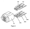
- is an exploded view of the connector of
Figure 1 ; - Figure 4
- is a perspective view of the connector according to a second embodiment of the invention;
- Figure 5
- is a sectional view of the connector of
Figure 4 ; - Figure 6
- is an exploded view of the connector of
Figure 4 ; - Figure 7
- is a front view of the bracket according to the invention;
- Figure 8
- is a cross-sectional view along line A-A of
Figure 7 ; - Figure 9
- is a cross-sectional view along line B-B of
Figure 7 ; - Figure 10
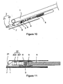
- is an exploded view of an endoscope according to an embodiment of the present invention; and
- Figure 11
- is a sectional view of the endoscope of
Figure 10 . - Like reference numerals refer to corresponding parts throughout the multiple views of the drawings.
- Reference will now be made in detail to embodiments, examples of which are illustrated in the accompanying drawings. In the following detailed description, numerous specific details are set forth in order to provide a thorough understanding of the subject matter presented herein. But it will be apparent to one of ordinary skill in the art that the subject matter may be practiced without these specific details. In other instances, well-known methods, procedures, components, and circuits have not been described in detail so as not to unnecessarily obscure aspects of the embodiments.
-
Figures 1 to 3 illustrate aconnector 9 according to a first embodiment of the invention, which is used to receive electric signals within a tubular structure such as an endoscope. As shown inFigures 1 to 3 , theconnector 9 comprises aninsulation body 100 and multipleconductive terminals 200 extending from thebody 100 that are fixed within thebody 100 through insert molding. Insert molding is a method of injecting melted resin into a mould after the ends of theterminals 200 are located into the mould. The resin is cured to fix the terminals and form an integrated product. The holdingportions 220 may be formed such that a side of the terminal 200 is bent to form a projection. In some embodiments, each holdingportion 220 has its own bending direction to balance the stress in different directions so that theterminals 220 and thebody 100 are tightly fixed together. In this embodiment, each terminal 200 has two symmetric holdingportions 220, although more than two can be used. Because (i) the connector is formed by insert molding and without the step of assembling theconductive terminals 200 and (ii) theinsulation body 100 and the holdingportions 220 are formed on the terminal 200, the connection of theterminals 200 within thebody 100 is strong. Further, insert molding is also efficient and therefore reduces the production cost, simplifies the manufacturing process, and increases the reliability of the connector. - The
conductive terminal 200 comprises a first conductiveterminal group 225 and a second conductiveterminal group 226 that are oppositely located. Each group comprises two exterior firstconductive terminals 250 and a secondconductive terminal 251 between the two firstconductive terminals 250. Each of the first and second conductive terminals includes amain portion 250a, acontact portion 250b extending from themain portion 250a, and awelding portion 250c with a bent end. The holdingportion 220 is located on themain portion 250a Further, the holdingportions 220 of thefirst terminal 250 are symmetric with reference to the longitudinal axis of thefirst terminal 250, and the holdingportions 220 of thesecond terminal 251 are symmetric with reference to the transversal axis of thesecond terminal 251. The holdingportions 220 enhance the engagement force between theterminals 200 and theinsulation body 100 to tightly fix theterminals 200 within thebody 100. Awelding pad 224 with one or more guidinggrooves 111 is connected to the welding portion 223, and the guidinggrooves 111 can guide thewelding pad 224 accurately in the course of insert molding to weld related parts. - In some embodiments, the
insulation body 100 includes abody portion 113 and aconnection portion 112 connecting to thebody portion 113. Afirst projection 110 and asecond projection 114 are formed on theinsulation body 100 to prevent the connector from being assembled onto other components in a wrong way. The longitudinal axes of the projections may be parallel to the longitudinal axis of the terminals so as to distinguish the direction of the connector while assembling the same with the other components. - The
contact portion 250b of the terminal 200 inserts and connects to a printed circuit board (PCB, not shown), and thefirst projection 110 guides the insertion and connection of thecontact portion 250b. Thewelding portion 250c of the terminal 200 can connect to a sensor (not shown) by welding with the guidance of the guidinggrooves 111, and thesecond projection 114 also guides and locates the welding portion to prevent it from being connected to the sensor inversely. -
Figures 4 to 9 illustrate a connector according to a second embodiment of the invention. As shown inFigures 4 to 9 , theconnector 5 includes abody 51 andmultiple terminals 52 extending from thebody 51. Thebody 51 is formed with theterminals 52 by insert molding. Ends of the terminal 52 are electrically connected to animage sensor 3 and aPCB board 4 of an endoscope. The terminal 52 has ahead portion 50 that is flat and afoot portion 522. The top surface of thehead portion 50 is exposed at one end face of thebody 51 to form anengagement face 513. Thefoot portion 522 extends from the other end face of thebody 51. Multiple extendingportions 53 are formed by inclining thefoot portion 522 outward to provide the tight connection between the terminal 52 and thebody 51. - A
welding pad 511 is connected to thehead portion 50 and has at least one guidinggroove 512 to precisely locate thewelding pad 511 in the course of insert molding. - In some embodiments, the
body 51 has afirst projection 54 and asecond projection 55 whose longitudinal axes may be parallel to the longitudinal axes of the terminals. Theprojections - The
foot portion 522 of the terminal 52 inserts and connects to a PCB board (not shown) with the guidance of thefirst projection 54. Thewelding pad 511 of the terminal 52 can connect to a sensor (not shown) by welding with the guidance of the guidinggrooves 512, and thesecond projection 55. - The present invention also discloses a method of manufacturing the connector, which includes the following steps: pressing the material belt to form a conductive terminal; bending and extending one end of the conductive terminal to form a clamping portion; and putting at least one of the conductive terminals so obtained in position within a mould, then folding the mould and insert molding to form a connector having an insulation body and conductive terminals. In the step of pressing the material belt to form a conductive terminal, two or more clamping portions having different bending directions are formed.
-
Figures 10 and 11 illustrate an endoscope according to another example of the invention. As shown inFigures 10 and 11 , the endoscope includes atelescope 1, an imaging means 2, animage sensor 3 such as a CCD image sensor that converts the optical images from the imaging means 2 to electronic signals, and aPCB board 4 that organizes and outputs the electronic signals. The imaging means 2 includes a group of lens, and the imaging means 2,image sensor 3 and thePCB board 4 are located in thetelescope 1. The endoscope further includes aconnector 5, such as the aforementioned connectors with reference toFigures 1 to 3 and aclamping bracket 6. Theimage sensor 3 and thePCB board 4 are connected together as a first assembly by theconnector 5. One end of thebracket 6 connects to the output end of the imaging means 2 to form a second assembly, and another end of the bracket is fixed to the first assembly so as to integrate the first and second assemblies. Thebracket 6 can be tubular. Therefore, the components in thetelescope 1 are integrated together via theconnector 5 and thebracket 6 as a simple structure with a precise location to provide high quality images. - The imaging means 2 includes a
lens 21 and alens group 22 located at the front end of thetelescope 1. The output end of the imaging means 2 is connected to one end of thebracket 6 via glue dots. Thelens group 22 includes atube 221 andmultiple lenses 222 within thetube 221. The front end of thebracket 6 partially surrounds the outer wall of thetube 221 along the axial direction of thetelescope 1. Because there is a focus tolerance up to 1 mm between thelens group 22 and theimage sensor 3 when the optical signals are transmitted, the location of thelens group 222 relative to theimage sensor 3 can be axially adjusted during the course of mounting thetube 221 to thebracket 6 via glue dots to adjust the focus. In some embodiments, the bracket surrounds theentire tube 221 along the axial direction of thetelescope 1 or thebracket 6 may surroundmultiple lenses 222 without using thetube 221. In this case, focus is adjusted by adjusting theimage sensor 3 under this situation. -
Optical fiber 7 is attached to the inner wall of thetelescope 1 via glue. Theoptical fiber 7 illuminates the area around thelens 21 via an outside source for taking pictures by thelens 21. - While assembling the first assembly, the
image sensor 3 and theengagement face 513 of theconnector 5 are coupled together by surface mounted technology (SMT) so as to form an electrical connection to thehead portion 50 of the terminal 52. The output end of thePCB board 4 is electrically connected to thefoot portion 522 of the terminal 52. - As shown in
Figure 4 , a bar-like projection 54 is formed on the outer wall of thebody 51 of theconnector 5 along the axial direction of thetelescope 1 for the convenient engagement between theconnector 5 and thebracket 6. Since theimage sensor 4 and thePCB board 4 connecting to theconnector 5 have an orientation, theprojection 5 can guide the operators to assemble theimage sensor 3 and thePCB board 4 properly. - As shown in
Figures 8 and 9 , thebracket 6 is tubular, with one end being fixed at the output end of the imaging means 2 and the other end surrounding and being fixed at theconnector 5. Agroove 61 is formed in the inner wall of the bracket 69 to match theprojection 54 of theconnector 5. When theconnector 5 is fixed onto thebracket 6, theprojection 54 inserts into thegroove 61. Note that the locations of thegroove 61 and theprojection 54 form a projection-groove configuration on theconnector 5 andbracket 6. For instance, theprojection 54 can be formed on the inner wall of thebracket 6 and thegroove 61 can be formed in the outer wall of theconnector 5. - In some embodiments, a
glue dot groove 62 is formed on the inner wall at the end of thebracket 6 that works in concert with theconnector 5 to control the glue amount used to connect theconnector 5 and thebracket 6. In one embodiment, there is a tolerance between thebracket 6 andconnector 5 along the radial direction of thetelescope 1 at the end ofbracket 6. By fixing theconnector 5 andbracket 6 using glue, the focus can be adjusted by radially adjusting the relative position of theconnector 5 to thebracket 6. Further, astep portion 63 is formed on the inner wall of thebracket 6 at a position corresponding to the position between the output end of the imaging means 2 and the first assembly to strengthen thebracket 6. - Signals are transmitted as shown in
Figure 11 . An image produced by thelens 21 is transmitted by thelens group 22 to the sensitive area of theimage sensor 3, which converts the image into electrical signals and outputs he signals to thePCB board 4 for filtering. The filtered electrical signals are transmitted to another PCB board (not shown) via a digital cable 8 and are displayed as a final picture on a display means (not shown). - The invention also provides a method to make the endoscope that includes the following steps: connecting the
image sensor 3 and thePCB board 4 via theconnector 5 to form the first assembly; connecting an end of thebracket 6 to the output end of the imaging means 2 to form the second assembly; connecting the other end of thebracket 6 to the first assembly to integrate the first and second assemblies; locatingoptical fiber 7 on the inner wall of thetelescope 1 and fixing the same via glue dots; and putting the integrated first and second assemblies into thetelescope 1 having theoptical fiber 7 and fixing the same with glue dots. In some embodiments, theoptical fiber 7 can be heat treated to withstand the heat load brought by the outside light source and to become expansible to have the components in thetelescope 1 connected more tightly. - When connecting the imaging means 2 and the
bracket 6 or connecting the first assembly and thebracket 6, the focus is adjusted before fixing the relative components. The focus adjustment can be done by axially adjusting the relative position between the imaging means 2 and thebracket 6, by radially adjusting the relative position between thebracket 6 and the first assembly, or by simultaneously adjusting the imaging means 2 and the relative position between the first assembly and thebracket 6. - According to this method, the
connector 5 and thebracket 6 integrate the components in thetelescope 1 into one body to position them precisely, improve the image quality, and simplify the manufacturing method. - The foregoing description, for purpose of explanation, has been described with reference to specific embodiments. However, the illustrative discussions above are not intended to be exhaustive or to limit the invention to the precise forms disclosed. Many modifications and variations are possible in view of the above teachings. The embodiments were chosen and described in order to best explain the principles of the invention and its practical applications, to thereby enable others skilled in the art to best utilize the invention and various embodiments with various modifications as are suited to the particular use contemplated.
Claims (15)
- A connector (9) for use in an endoscope, comprising: an insulation body (100); and one or more conductive terminals (200, 52) within the insulation body (100), wherein the one or more conductive terminals (200, 52) comprise at least one clamping portion (220, 53) to clamp onto the insulation body (100), the clamping portion (220, 53) is configured to be a projection by bending a side edge of the one or more terminals (200, 52), the conductive terminal (200, 52) comprises a body (250a), a contacting part (250b) extending from one end of the body (250a), and a welding part (250c) extending from the other end of the body (250a) to configure a bending portion, a pad (224) is formed on the welding part (250c), and guiding grooves (111) are formed on the pad (224).
- The connector (9) according to claim 1, wherein the conductive terminal (200, 52) comprises a first conductive terminal group (225) and a second conductive terminal group (226) that are oppositely located.
- The connector (9) according to claim 2, wherein each of the first conductive terminal group (225) and the second conductive terminal group (226) comprises two exterior first conductive terminals (250) and a second conductive terminal (251) between the two first conductive terminals (250).
- The connector (9) according to claim 1, wherein, each of the conductive terminals (200, 52) comprises two or more clamping portions (220, 53), and their respective bending directions are different from each other.
- The connector (9) according to any one of claims 1 to 4, wherein the conductive terminal comprises two symmetric clamping portions (220, 53).
- The connector according to claim 1, wherein the clamping portions (220, 53) are formed on the body (250a).
- The connector (9) according to any one of claims 1 to 6, wherein the insulation body (100) comprises a body portion (113) and a connection portion (112) connecting to the body portion (113).
- The connector (9) according to any one of claims 1 to 7, wherein at least one projection (110, 114) is formed on the insulation body (100), and the conductive terminals (200, 52) have longitudinal axis parallel to the longitudinal axis of the at least one projection (110, 114).
- The connector (9) according to any one of claims 1 to 7, wherein the insulation body (100) is configured to be a column.
- The connector (9) according to any one of claims 1 to 9, formed by pressing a material belt to form the conductive terminal (200, 52), bending and extending an end of the conductive terminal (200, 52) to form the clamping portion (220, 53), positioning the conductive terminal (200, 52) within a mould, folding the mould and performing insert molding.
- A connector (5) for use in an endoscope according to claim 1, whereby, the terminal (52) is configured to include a head portion (50) and a foot portion (522), the head portion (50) has an upper end exposed out of the end face of the insulation body (51) and forms an engagement face (513) with the end face, the foot portion (522) is formed by bending the extension of the head portion (50) and extends out of the other end face of the insulation body (51), and the foot portion (522) extends to form an extension portion (53) for connecting the terminal (52) to the body (51), a welding pad (511) is configured to connect to the head portion (50), and the insulation body (51) has at least one groove (51) formed on the pad (511).
- The connector (5) according to claim 11, wherein the extension portion (53) is symmetric.
- The connector (5) according to claim 11 or 12, wherein at least one projection (54, 55) is arranged on the insulation body (51), and the conductive terminals (52) have longitudinal axis parallel to the longitudinal axis of the at least one projection (54, 55).
- The connector (5) according to claim 11 or 12, wherein the insulation body (51) is configured to be a column.
- The connector (5) according to any one of claims 11 to 14, formed by pressing a material belt to form the conductive terminal (52), bending and extending an end of the conductive terminal (52) to form the clamping portion (53), positioning the conductive terminal (52) within a mould, folding the mould and performing insert molding.
Applications Claiming Priority (3)
| Application Number | Priority Date | Filing Date | Title |
|---|---|---|---|
| CNU2008200956570U CN201239129Y (en) | 2008-07-18 | 2008-07-18 | Connector |
| CNU200820095923XU CN201239130Y (en) | 2008-07-25 | 2008-07-25 | Connector and endoscope including the same |
| CN200810142658A CN101635400A (en) | 2008-07-25 | 2008-07-25 | Connector and manufacturing method thereof |
Publications (3)
| Publication Number | Publication Date |
|---|---|
| EP2145576A2 EP2145576A2 (en) | 2010-01-20 |
| EP2145576A3 EP2145576A3 (en) | 2012-07-18 |
| EP2145576B1 true EP2145576B1 (en) | 2014-11-19 |
Family
ID=41210957
Family Applications (1)
| Application Number | Title | Priority Date | Filing Date |
|---|---|---|---|
| EP09002087.6A Active EP2145576B1 (en) | 2008-07-18 | 2009-02-14 | A connector |
Country Status (2)
| Country | Link |
|---|---|
| US (1) | US8011973B2 (en) |
| EP (1) | EP2145576B1 (en) |
Families Citing this family (6)
| Publication number | Priority date | Publication date | Assignee | Title |
|---|---|---|---|---|
| CN102683453A (en) * | 2012-05-24 | 2012-09-19 | 无锡华昊电器有限公司 | Diode installation connecting device for photovoltaic junction box |
| KR102248086B1 (en) * | 2014-11-14 | 2021-05-04 | 엘지이노텍 주식회사 | Camera module using for automobile |
| USD1012284S1 (en) * | 2022-02-09 | 2024-01-23 | Boston Scientific Scimed, Inc. | Medical device system and removable connectors set |
| CN118946301A (en) | 2022-02-09 | 2024-11-12 | 波士顿科学国际有限公司 | Medical device system with removable connector |
| CN115539868B (en) * | 2022-12-01 | 2023-03-17 | 深圳市旺坤光电技术有限公司 | Landscape lamp with changeable lamp holder mounting position |
| USD1121158S1 (en) | 2024-04-23 | 2026-03-31 | Boston Scientific Scimed, Inc. | Portion of medical console |
Family Cites Families (11)
| Publication number | Priority date | Publication date | Assignee | Title |
|---|---|---|---|---|
| US2445537A (en) | 1945-07-14 | 1948-07-20 | Edward G Schaeffer | Method of producing electrical outlet plugs |
| DE2558003C3 (en) * | 1975-12-22 | 1980-06-12 | Georg 8260 Muehldorf Kolm | Electrical connector |
| US5013264A (en) * | 1989-09-25 | 1991-05-07 | Robinson Nugent, Inc. | Edge card connector having preloaded contacts |
| US5203813A (en) * | 1991-08-06 | 1993-04-20 | Airborn, Inc. | Low entry force connector socket method of manufacture |
| US6206735B1 (en) | 1998-08-28 | 2001-03-27 | Teka Interconnection Systems, Inc. | Press fit print circuit board connector |
| TW393812B (en) * | 1998-12-24 | 2000-06-11 | Hon Hai Prec Ind Co Ltd | A manufacturing method of high-density electrical connector and its product |
| US6855013B2 (en) * | 2000-05-08 | 2005-02-15 | Tyco Electronic Logistics Ag | LCD connector for printed circuit boards |
| US6796852B2 (en) | 2001-07-23 | 2004-09-28 | Sumitomo Wiring Systems, Ltd. | Connector and method for producing the same |
| US6821162B2 (en) * | 2002-07-26 | 2004-11-23 | Fci Americas Technology, Inc. | Integrated flange seal electrical connection |
| CN100479267C (en) * | 2006-05-18 | 2009-04-15 | 东莞市夏亿电子科技有限公司 | High-frequency connector |
| US7347746B1 (en) * | 2006-10-27 | 2008-03-25 | Boston Scientific Neuromodulation Corporation | Receptacle connector assembly |
-
2008
- 2008-12-30 US US12/346,753 patent/US8011973B2/en active Active
-
2009
- 2009-02-14 EP EP09002087.6A patent/EP2145576B1/en active Active
Also Published As
| Publication number | Publication date |
|---|---|
| EP2145576A3 (en) | 2012-07-18 |
| US8011973B2 (en) | 2011-09-06 |
| EP2145576A2 (en) | 2010-01-20 |
| US20100015857A1 (en) | 2010-01-21 |
Similar Documents
| Publication | Publication Date | Title |
|---|---|---|
| EP2147629B1 (en) | An endoscope and a method of manufacturing the same | |
| CN101634749B (en) | Endoscope | |
| EP2145576A2 (en) | A connector and a method of manufacturing the same | |
| JP7828416B2 (en) | Coaxial Connectors | |
| EP2880482B1 (en) | Opto-electronic contact and method | |
| US8356950B2 (en) | Camera module and method for manufacturing camera module | |
| CN112042177B (en) | Camera module | |
| CN112015029B (en) | Optical device with heating element | |
| US20100304579A1 (en) | Low Resistance Connector For Printed Circuit Board | |
| US20080019643A1 (en) | Optical subassembly having insertable cylindrical sleeve | |
| US20060025651A1 (en) | Endoscope electronics assembly | |
| US8616901B2 (en) | Circuit board assembly, board device, and method for assembling circuit board assembly | |
| CN101093920A (en) | Electronic equipment and method of manufacturing the electronic equipment | |
| US10403995B2 (en) | Electrical connector, electronic component, and assembly method | |
| JP2020154304A (en) | Structure of endoscope device | |
| US20170131490A1 (en) | Optical fiber cable-equipped connector | |
| KR20150131059A (en) | Stereo camera module and method for the production thereof | |
| CN201239130Y (en) | Connector and endoscope including the same | |
| US20170071462A1 (en) | Video endoscope | |
| US7672060B2 (en) | Lens unit | |
| US20190320096A1 (en) | Camera device and assembling method for same | |
| CN104425925B (en) | The connection structure of module and module and butt connector | |
| US7893992B2 (en) | Device comprising a camera module with automatic focusing and corresponding assembly method | |
| JP2000125161A (en) | Imaging device | |
| KR20120094668A (en) | Stereo camera and a fabricating method the same |
Legal Events
| Date | Code | Title | Description |
|---|---|---|---|
| PUAI | Public reference made under article 153(3) epc to a published international application that has entered the european phase |
Free format text: ORIGINAL CODE: 0009012 |
|
| AK | Designated contracting states |
Kind code of ref document: A2 Designated state(s): AT BE BG CH CY CZ DE DK EE ES FI FR GB GR HR HU IE IS IT LI LT LU LV MC MK MT NL NO PL PT RO SE SI SK TR |
|
| AX | Request for extension of the european patent |
Extension state: AL BA RS |
|
| 17P | Request for examination filed |
Effective date: 20100421 |
|
| PUAL | Search report despatched |
Free format text: ORIGINAL CODE: 0009013 |
|
| AK | Designated contracting states |
Kind code of ref document: A3 Designated state(s): AT BE BG CH CY CZ DE DK EE ES FI FR GB GR HR HU IE IS IT LI LT LU LV MC MK MT NL NO PL PT RO SE SI SK TR |
|
| AX | Request for extension of the european patent |
Extension state: AL BA RS |
|
| RIC1 | Information provided on ipc code assigned before grant |
Ipc: H01R 43/16 20060101ALI20120613BHEP Ipc: H01R 43/24 20060101ALI20120613BHEP Ipc: H01R 13/405 20060101ALI20120613BHEP Ipc: A61B 1/00 20060101AFI20120613BHEP |
|
| AKX | Designation fees paid |
Designated state(s): DE FR GB IT |
|
| GRAP | Despatch of communication of intention to grant a patent |
Free format text: ORIGINAL CODE: EPIDOSNIGR1 |
|
| INTG | Intention to grant announced |
Effective date: 20140606 |
|
| RIN1 | Information on inventor provided before grant (corrected) |
Inventor name: JIANG, FENG Inventor name: ZHANG, ZIFENG Inventor name: WANG, KUN Inventor name: WANG, ZHENBO Inventor name: HUANG, ZHIXUE |
|
| GRAS | Grant fee paid |
Free format text: ORIGINAL CODE: EPIDOSNIGR3 |
|
| GRAA | (expected) grant |
Free format text: ORIGINAL CODE: 0009210 |
|
| AK | Designated contracting states |
Kind code of ref document: B1 Designated state(s): DE FR GB IT |
|
| REG | Reference to a national code |
Ref country code: GB Ref legal event code: FG4D |
|
| REG | Reference to a national code |
Ref country code: DE Ref legal event code: R096 Ref document number: 602009027812 Country of ref document: DE Effective date: 20141231 |
|
| REG | Reference to a national code |
Ref country code: FR Ref legal event code: PLFP Year of fee payment: 7 |
|
| REG | Reference to a national code |
Ref country code: DE Ref legal event code: R097 Ref document number: 602009027812 Country of ref document: DE |
|
| PLBE | No opposition filed within time limit |
Free format text: ORIGINAL CODE: 0009261 |
|
| STAA | Information on the status of an ep patent application or granted ep patent |
Free format text: STATUS: NO OPPOSITION FILED WITHIN TIME LIMIT |
|
| 26N | No opposition filed |
Effective date: 20150820 |
|
| PG25 | Lapsed in a contracting state [announced via postgrant information from national office to epo] |
Ref country code: IT Free format text: LAPSE BECAUSE OF FAILURE TO SUBMIT A TRANSLATION OF THE DESCRIPTION OR TO PAY THE FEE WITHIN THE PRESCRIBED TIME-LIMIT Effective date: 20141119 |
|
| REG | Reference to a national code |
Ref country code: FR Ref legal event code: PLFP Year of fee payment: 8 |
|
| REG | Reference to a national code |
Ref country code: FR Ref legal event code: PLFP Year of fee payment: 9 |
|
| REG | Reference to a national code |
Ref country code: FR Ref legal event code: PLFP Year of fee payment: 10 |
|
| P01 | Opt-out of the competence of the unified patent court (upc) registered |
Effective date: 20230527 |
|
| PGFP | Annual fee paid to national office [announced via postgrant information from national office to epo] |
Ref country code: GB Payment date: 20260219 Year of fee payment: 18 |
|
| PGFP | Annual fee paid to national office [announced via postgrant information from national office to epo] |
Ref country code: DE Payment date: 20260217 Year of fee payment: 18 |
|
| PGFP | Annual fee paid to national office [announced via postgrant information from national office to epo] |
Ref country code: FR Payment date: 20260223 Year of fee payment: 18 |