EP2145319B1 - Vehicle monitor - Google Patents
Vehicle monitor Download PDFInfo
- Publication number
- EP2145319B1 EP2145319B1 EP08748104A EP08748104A EP2145319B1 EP 2145319 B1 EP2145319 B1 EP 2145319B1 EP 08748104 A EP08748104 A EP 08748104A EP 08748104 A EP08748104 A EP 08748104A EP 2145319 B1 EP2145319 B1 EP 2145319B1
- Authority
- EP
- European Patent Office
- Prior art keywords
- portable device
- vehicle
- sensor unit
- reset
- statistic
- Prior art date
- Legal status (The legal status is an assumption and is not a legal conclusion. Google has not performed a legal analysis and makes no representation as to the accuracy of the status listed.)
- Active
Links
Images




Classifications
-
- G—PHYSICS
- G01—MEASURING; TESTING
- G01P—MEASURING LINEAR OR ANGULAR SPEED, ACCELERATION, DECELERATION, OR SHOCK; INDICATING PRESENCE, ABSENCE, OR DIRECTION, OF MOVEMENT
- G01P1/00—Details of instruments
- G01P1/07—Indicating devices, e.g. for remote indication
-
- G—PHYSICS
- G07—CHECKING-DEVICES
- G07C—TIME OR ATTENDANCE REGISTERS; REGISTERING OR INDICATING THE WORKING OF MACHINES; GENERATING RANDOM NUMBERS; VOTING OR LOTTERY APPARATUS; ARRANGEMENTS, SYSTEMS OR APPARATUS FOR CHECKING NOT PROVIDED FOR ELSEWHERE
- G07C5/00—Registering or indicating the working of vehicles
- G07C5/08—Registering or indicating performance data other than driving, working, idle, or waiting time, with or without registering driving, working, idle or waiting time
- G07C5/0816—Indicating performance data, e.g. occurrence of a malfunction
- G07C5/0825—Indicating performance data, e.g. occurrence of a malfunction using optical means
-
- G—PHYSICS
- G07—CHECKING-DEVICES
- G07C—TIME OR ATTENDANCE REGISTERS; REGISTERING OR INDICATING THE WORKING OF MACHINES; GENERATING RANDOM NUMBERS; VOTING OR LOTTERY APPARATUS; ARRANGEMENTS, SYSTEMS OR APPARATUS FOR CHECKING NOT PROVIDED FOR ELSEWHERE
- G07C5/00—Registering or indicating the working of vehicles
- G07C5/08—Registering or indicating performance data other than driving, working, idle, or waiting time, with or without registering driving, working, idle or waiting time
- G07C5/0841—Registering performance data
- G07C5/085—Registering performance data using electronic data carriers
- G07C5/0858—Registering performance data using electronic data carriers wherein the data carrier is removable
-
- H—ELECTRICITY
- H04—ELECTRIC COMMUNICATION TECHNIQUE
- H04Q—SELECTING
- H04Q9/00—Arrangements in telecontrol or telemetry systems for selectively calling a substation from a main station, in which substation desired apparatus is selected for applying a control signal thereto or for obtaining measured values therefrom
-
- G—PHYSICS
- G07—CHECKING-DEVICES
- G07C—TIME OR ATTENDANCE REGISTERS; REGISTERING OR INDICATING THE WORKING OF MACHINES; GENERATING RANDOM NUMBERS; VOTING OR LOTTERY APPARATUS; ARRANGEMENTS, SYSTEMS OR APPARATUS FOR CHECKING NOT PROVIDED FOR ELSEWHERE
- G07C2209/00—Indexing scheme relating to groups G07C9/00 - G07C9/38
- G07C2209/60—Indexing scheme relating to groups G07C9/00174 - G07C9/00944
- G07C2209/62—Comprising means for indicating the status of the lock
-
- G—PHYSICS
- G07—CHECKING-DEVICES
- G07C—TIME OR ATTENDANCE REGISTERS; REGISTERING OR INDICATING THE WORKING OF MACHINES; GENERATING RANDOM NUMBERS; VOTING OR LOTTERY APPARATUS; ARRANGEMENTS, SYSTEMS OR APPARATUS FOR CHECKING NOT PROVIDED FOR ELSEWHERE
- G07C5/00—Registering or indicating the working of vehicles
- G07C5/008—Registering or indicating the working of vehicles communicating information to a remotely located station
-
- H—ELECTRICITY
- H04—ELECTRIC COMMUNICATION TECHNIQUE
- H04Q—SELECTING
- H04Q2209/00—Arrangements in telecontrol or telemetry systems
- H04Q2209/40—Arrangements in telecontrol or telemetry systems using a wireless architecture
-
- H—ELECTRICITY
- H04—ELECTRIC COMMUNICATION TECHNIQUE
- H04Q—SELECTING
- H04Q2209/00—Arrangements in telecontrol or telemetry systems
- H04Q2209/50—Arrangements in telecontrol or telemetry systems using a mobile data collecting device, e.g. walk by or drive by
-
- H—ELECTRICITY
- H04—ELECTRIC COMMUNICATION TECHNIQUE
- H04Q—SELECTING
- H04Q2209/00—Arrangements in telecontrol or telemetry systems
- H04Q2209/70—Arrangements in the main station, i.e. central controller
- H04Q2209/75—Arrangements in the main station, i.e. central controller by polling or interrogating the sub-stations
Definitions
- the embodiments described herein relate to a system and method for vehicle monitoring and more particularly to a system and method for collecting and displaying vehicle statistics.
- OBD-II ports are currently available in some or all vehicles.
- OBD-II ports are available in all post-1996 vehicles.
- An OBD-II port is a standardized digital communications port designed to provide real-time data regarding vehicle functioning in addition to a standardized series of diagnostic trouble codes. This data may be collected by connecting a device to the OBD-II port which is capable of communicating using, for example, the SAE J1850 standard.
- German patent application DE 10 2006 011704 A1, filed March 14, 2006 generally discloses a method and apparatus for controlling the operation of a vehicle, where the apparatus includes an input mechanism configured to receive an action of the operator that is indicative of the operation to be performed by the vehicle, a transmitter configured to send a first signal via a wireless connection with the vehicle that at least partially embodies a command for the action of the operator received by the input mechanism, a receiver configured to receive a second signal via the wireless connection with the vehicle that at least partially embodies feedback from a sensor of the vehicle indicative of the operation resulting from the command at least partially embodied by the first signal sent by the transmitter, and output equipment configured to present information to the operator on the operation based at least in part on the feedback in the second signal received by the receiver.
- German patent application DE 195 22 937 A1 filed June 23, 1995 , generally discloses a portable diagnosing apparatus for reading data from an electronic unit of a vehicle and sending the data to an external computer by wireless connection, where the external computer conducts miscellaneous calculations based on the sent data and displays results on the external computer or analyses failures of the vehicle in a running state. Furthermore, service manuals are sent from the external computer to a display of the portable diagnosing apparatus when needed according to a command from the portable diagnosing apparatus.
- German utility model DE 20 2004 011207 U1 filed on July 16, 2004 , generally discloses a portable data carrier/organizer for optically receiving data from a source as bits in series or in parallel, and displaying desired data selected via a keypad operation on a screen built into a key-fob. Furthermore, outdated data is overwritten when data is updated.
- German patent application DE 100 55 059 A1 filed on November 7, 2000 , generally discloses an onboard measurement or an onboard diagnosis system collecting data relating to fuel usage and distance travelled to calculate emission data and maintenance data of the vehicle.
- the calculated data is transferred to a mobile phone via a cable, which is then transferred to a central collection point.
- the collected data can be used by companies, regional and national governments etc.
- the collected data can also be used to encourage drivers to drive in a more environmentally friendly way using a suitable bonus scheme.
- DE 100 55 059 A1 discloses the following features of claim 1 - a system for monitoring a vehicle, the system comprising: a sensor unit; and a portable device comprising a processor configured to control the portable device, a display for displaying vehicle statistics and a transceiver for communicating with the sensor unit.
- At least one embodiment described herein provides a system for monitoring a vehicle as claimed In claim 1.
- the system comprises a sensor unit for collecting at least one vehicle statistic and a portable device.
- the portable device comprises a processor configured to control the portable device and request and receive the at least one vehicle statistic from the sensor unit; a display for displaying at least one of the at least one vehicle statistic; and a transceiver configured to communicate with the sensor unit.
- At least one embodiment described herein provides a portable device for displaying at least one vehicle statistic for a vehicle.
- the portable device comprises a transceiver configured to communicate with a sensor unit that collects at least one vehicle statistic; a processor configured to control the portable device and request and receive the at least one vehicle statistic; and a display for displaying at least one of the at least one vehicle statistic.
- the portable device is a handheld device.
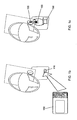
- FIG. 1A is a diagram of a portable device according to one exemplary embodiment
- FIG. 1B is a diagram showing a sensor unit according to one exemplary embodiment being attached to a vehicle
- FIG. 1C is a diagram showing the portable device of FIG. 1A and the sensor unit of FIG 1B in use;
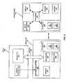
- FIG. 2 is a block diagram of a vehicle monitoring system
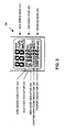
- FIG. 3 is a diagram showing a display of the portable device of FIG. 1A ;
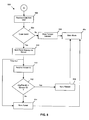
- FIG. 4 is a flowchart diagram illustrating the steps for an exemplary embodiment of a method used to display and update vehicle statistics on the portable device;
- FIG. 5 is a flowchart diagram illustrating the steps for an exemplary embodiment of a method used to synchronize the portable display with the sensor unit;
- FIG. 6 is a flowchart diagram illustrating the steps for an exemplary embodiment of a method used to change the access code on the portable display
- FIG. 7 is a flowchart diagram illustrating the steps for an exemplary embodiment of a method used to reset the memory on the portable device.
- FIG. 8 is a flowchart diagram illustrating the steps for an exemplary embodiment of a method used to retrieve vehicle statistics from the vehicle, store them in the sensor unit and send updated vehicle statistics to the portable device.
- FIG. 1A illustrates a portable device 100 according to one exemplary embodiment of the invention.
- the portable device 100 includes a display 120, for displaying vehicle statistics, and three input buttons 110, 112, and 114, for receiving input from the user.
- the portable device 100 is removably attachable to the key 105 used to operate the vehicle to be monitored.
- the input buttons 110, 112, and 114 have a variety of functions.
- the first button 110 is a synchronization button. If the synchronization button 110 is pressed and released then the display 120 will toggle between a metric mode and an imperial mode. If the synchronization button 110 is held for at least three seconds then the display 120 will toggle between a main mode and a synchronization mode. The synchronization mode will be discussed in further detail with reference to FIG. 5 .
- the second button 112 is a reset button. If the reset button 112 is pressed and released, the portable device 100 will request updated vehicle statistics from a sensor unit 150. If the reset button 112 is held for at least three seconds then the portable device 100 will enter a reset mode. The reset mode will be discussed in further detail with reference to FIG. 7 . From the reset mode, the reset button 112 allows an access code to be entered.
- the last button 114 is a code button.
- the code button 114 will cause the portable device 100 to enter into a change code mode when held for at least three seconds.
- the change code mode will be discussed in greater detail with reference to FIG. 6 .
- the reset button 112 can be used to increment each digit and the code button 114 is used to confirm the digits that are selected.
- the current code must be entered using the reset and code buttons before the code can be changed. Once the current code has been verified, the new code can be entered. The code allows the user to access certain functions on the portable device 100 and provides a level of security.
- a sensor unit 150 is shown which is releasably attachable to a port 116 of the vehicle to be monitored.
- the port 116 is an OBD-II port but other embodiments can use other technology and techniques which allow for the collection of vehicle statistics, such as accelerometers, speedometers or GPS systems and the like.
- the sensor unit 150 is shown attached to the OBD-II port 116 of the vehicle.
- the sensor unit 150 communicates with the portable device 100 which is releasably attachable to the vehicle key 105.
- FIG. 2 illustrates the components for an exemplary embodiment of a vehicle monitoring system 200.
- the vehicle monitoring system 200 includes the portable device 100 and the sensor unit 150 which communicates with the monitored vehicle 210 through data bus 220.
- the portable device 100 and the sensor unit 150 communicate using two radio frequency (RF) modules 248 and 238.
- RF radio frequency
- the vehicle 210 includes, among many other components, a vehicle battery 212 and a vehicle engine control unit (ECU) 214.
- the vehicle battery 212 can be used to provide power to the sensor unit 150.
- the vehicle ECU 214 captures vehicle information and responds to information requests from the sensor unit 150.
- the sensor unit 150 will continually query the vehicle ECU 214 for the current speed of the vehicle 210 through the data bus 220.
- the sensor unit 150 connects to the type A vehicle connector of the vehicle 210 as specified in the SAE J1962 standard.
- the sensor unit 150 includes, but is not limited to, a voltage regulator 232, a memory 234, a processor 236, two indicators 239 and an RF module 238.
- the RF module 238 is used to communicate with the portable device 100.
- the RF module 238 consists of receiver circuitry 238a (RX) and transmitter circuitry 238b (TX).
- the indicators 239 inform the user of the state of the sensor unit 150 (i.e. if it is functional).
- the indicators may be light-emitting diodes (LEDs) or the like.
- the memory 234 is a nonvolatile memory, such as an EEPROM, used to store statistics and data in case power is removed from the sensor unit 150.
- the voltage regulator 232 connects to the vehicle battery 212.
- the voltage regulator 232 drops the 12 volts supplied by the vehicle battery to 5 volts needed by the sensor unit 150.
- the portable device 100 may be a key fob unit, similar to a car starter key fob, or any other portable device. It includes, but is not limited to, a group of input mechanisms 242, a battery 243, a memory 244, a processor 246, an RF module 248 and a display 249.
- the RF module 248 is used to communicate with the sensor unit 150.
- the RF module 248 consists of receiver circuitry 248a (RX) and transmitter circuitry 248b (TX).
- the input mechanisms 242 such as input buttons, are used by the user to enter information or change settings on the portable device 100.
- the display 249 displays information to the user, including, but not limited to, vehicle statistics.
- the memory 244 is a nonvolatile memory, such as an EEPROM, used to store statistics and data in case power is removed from the portable device 100.
- the processor 246 controls the operations of the portable device 100.
- the battery 243 provides power to the portable device 100.
- the sensor unit 150 will normally remain attached to the vehicle 210 while the portable device 100, which contains the same vehicle statistics as the sensor unit 150, may be easily transported to and from the vehicle 210. Since the portable device 100 is portable, the driving habits of a driver may be monitored without the need to enter the vehicle 210 or even to be in proximity of the vehicle 210. Since the sensor unit 150 normally remains attached to the vehicle 210, there is no possibility that a driver will mistakenly forget to attach it prior to operating the vehicle 210. Even if the portable device is not in proximity of the vehicle 210 when the vehicle is being operated, for example if the portable device is left at home, the sensor unit 150 will continue to collect statistics.
- the portable device 100 may be removably attached to the keys used to operate the vehicle 210 or to any other object or personal item but preferably to an object which would normally accompany a driver in the vehicle 210. Attaching the portable device 100 in such a way reduces the likelihood that the vehicle 210 will mistakenly be operated without the portable device 100 being present, thus increasing the likelihood that the statistics displayed on the portable device will be up to date.
- the portable device 100 may be placed in a wallet or purse or similar personal item.
- FIG. 3 illustrates the display 120 of the portable device 100 in more detail.
- the display includes several fields of information.
- the maximum speed field 310 displays the maximum speed which the vehicle 210 has attained since the last time the portable device 100 was reset.
- the maximum speed may be displayed in metric (km/h) or imperial (mph) depending on the display mode of the portable device 100.
- the distance field 320 displays the distance the vehicle 210 has traveled since the last time the portable device 100 was reset. The distance may be displayed in metric (km) or imperial (mi) depending on the display mode of the portable device 100.
- the distance field 320 also includes three indicators 322, 324 and 326.
- the sync mode indicator 322 is present when the portable device 100 is in synchronization mode.
- the old code indicator 324 is present during a change code operation to indicate that the old access code is to be entered.
- the new code indicator 326 is present during a change code operation to indicate that the new access code is to be entered.
- the braking field 330 displays the number of times that a driver of the vehicle 210 has slammed on the brakes since the last time the portable device 100 was reset. This may be calculated by keeping track of the number of times in which the vehicle 210 has experienced a specified reduction in speed in a specified period of time. When the reset button 112 is held for at least three seconds then the braking field 330 will display the number of times that the portable device 100 has been reset.
- the braking field 330 also includes two indicators 332 and 334.
- the confirm new code indicator 332 is present during a change code operation to indicate that a new access code needs to be confirmed.
- the tamper indicator 334 indicates that tampering has been detected.
- FIG. 4 there is shown a flowchart diagram that illustrates a method 400 used to display and update vehicle statistics on the portable device 100.
- the method 400 starts at step 402 where the portable device 100 is first initiated and a start screen is displayed.
- the method 400 then proceeds to step 404 where the portable device 100 enters the main mode in which it waits to receive input from the user or for 30 seconds to pass with no input from the user.
- the portable device 100 will remain in the main mode until 30 seconds passes or until it receives input from the user. If the user presses the synchronization button 110 for less than three seconds, the method 400 proceeds to step 416 where the display mode will be changed from metric to imperial or from imperial to metric. If the synchronization button 110 is pressed for three seconds or more, the portable device 100 will enter the synchronization mode which will be discussed in relation to FIG. 5 . If the code button 114 is pressed for at least three seconds, the portable device 100 will enter the change code mode which will be discussed in relation to FIG. 6 . If the reset button 112 is pressed for three seconds or more then the portable device 100 will enter the reset mode which will be discussed in relation to FIG. 7 . If the reset button 114 is pressed for less than three seconds or if 30 seconds passes without any user input, the method 400 will proceed to step 406 to get updated vehicle statistics from the sensor unit 150.
- the portable device 100 requests an update from the sensor unit 150. If no response is received within a certain period of time (i.e., within 20ms) then the portable device 100 times out, the receiver circuitry 248a of the RF module 248 shuts down to conserve energy and the method 400 returns to the main mode in step 404.
- each portable device 100 has a unique device identification number and each sensor unit 150 has a sensor identification number which matches the device identification number of the portable device 100 to which it has been synchronized.
- the portable device 100 will include its device identification number in each update request sent to the sensor unit 150 and the sensor unit 150 will only respond to update requests containing a matching identification number. This fact, along with the short time out period, means that the sensor unit 150 does not need to send its sensor identification number with each update message. This provides for shorter update messages from the sensor unit 150 and, hence, shorter response times which allows the portable device 100 to use an even shorter time out period and increases the life of the battery 243.
- step 408 the portable device 100 receives an update message from the sensor unit 150. This update message will include each of the statistics displayed on the portable device 100.
- the sensor unit 150 will keep a power cycle count of the number of times it has been powered up (i.e. the number of times it has been connected to the vehicle). This information will be sent to the portable device 100 each time an update message is sent. The portable device 100 will store the power cycle count received in the first message after the most recent reset operation. At step 410, the power cycle count received from the sensor unit 150 will be compared to the power cycle count stored in the portable device 100. If the two counts do not match, it is assumed that someone has removed the sensor 150 from port 116 and driven the vehicle 210 without the use of the sensor 150. This is considered to be tampering and, hence, the tamper indicator 334 is shown at step 412. The tamper indicator 334 will be displayed until the portable device 100 is reset as will be described with reference to FIG. 7 . The method 400 then proceeds to step 414. If the two counts do match, on the other hand, the method 400 proceeds directly to step 414.
- the statistics on the display 120 of the portable device 100 and in memory 244 are updated and the portable device 100 returns to the main mode at step 404.
- FIG. 5 there is shown a flowchart diagram which illustrates an exemplary embodiment of a method 500 used to synchronize the portable device 100 with the sensor unit 150.
- synchronization is used to avoid interference between sensor units and portable devices from different systems (i.e. so that a user will not mistakenly read vehicle information from the sensor unit of a neighboring vehicle or purposefully read the statistics from a sensor unit with more "acceptable" values).
- Second, synchronization makes it difficult for data to be retrieved from the sensor, unit 150 without the associated portable device 100 , allowing the data to remain private from unauthorized persons. Synchronization is required when installing the sensor for the first time.
- the method 500 is initiated when the portable device 100 enters the synchronization mode. At this point, the sync mode indicator 322 is activated. At step 502, the portable device 100 receives an access code from the user. The validity of this access code is checked at step 504. If it is not a valid code, the tamper indicator 334 is activated at step 506 and the portable device 100 returns to the main mode at step 404. If a valid code has been entered, the method 500 proceeds to step 508 to attempt a synchronization.
- the portable device 100 sends a synchronization message to the sensor unit 150.
- each portable device 100 has a unique, device identification number that can be factory set or randomly generated when the user enters the synchronization mode. If the sensor unit 150 is prepared to synchronize, it receives the device identification number from the portable device 100 in the synchronization message and this number becomes the sensor identification number. The sensor unit 150 then sends a message back to the portable device 100 including its newly set sensor identification number. If the sensor unit is not prepared to synchronize, no message is sent back from the sensor unit 150, the portable device times out, the synchronization fails and a fail message appears on the display 120 at step 514. The method 500 returns to the main mode in step 404. The sensor unit 150 and the portable device 100 will not be able to communicate until a synchronization has been successful.
- the sensor identification number received from the sensor unit 150 is compared to the portable device's 100 device identification number. If they are equal, the synchronization has passed.
- a pass message appears on the display 120 and the portable device 100 returns to the main mode at step 404. If the two identification numbers are not equal, the synchronization fails and a fail message appears on the display 120 at step 514.
- the method 500 returns to the main mode in step 404. The sensor unit 150 and the portable device 100 will not be able to communicate until a synchronization has been successful.
- FIG. 6 there is shown a flowchart diagram that illustrates an exemplary embodiment of a method 600 used to change the access code on the portable device 100.
- the method 600 is initiated when the portable device 100 enters the change code mode.
- the access code is required each time the information stored and displayed on the portable device 100 is reset. This code is initialized during manufacture and can be changed thereafter. An authorized user may wish to change this access code initially to prevent unauthorized users from resetting the portable device and then periodically or whenever it is suspected that an unauthorized user may have discovered the current access code in order to ensure the integrity of the information.
- the old code indicator is activated and the portable device 100 receives the old access code from the user.
- the validity of this access code is checked at step 604. If it is not a valid code, the tamper indicator 334 is activated at step 606 and the portable device 100 returns to the main mode at step 404. If a valid code has been entered, the method 600 proceeds to step 608.
- the new code indicator 326 is activated and a new access code is entered.
- both the new code indicator 326 and the confirm new code indicator 332 are activated and the new code is entered for a second time in order to confirm the new access code. If the same code is entered in steps 608 and 610 then the new code is confirmed at step 612 and the method 600 proceeds to step 616.
- the access code is changed to the new access code, a pass message is displayed on the display 120 and the portable device 100 returns to the main mode at step 404. If the same code is not entered in steps 608 and 610 then the code is not confirmed at step 612 and the method 600 proceeds to step 614.
- a fail message is displayed on the display 120 and the portable device 100 returns to the main mode at step 404 without having changed the access code.
- FIG. 7 there is shown a flowchart diagram which illustrates an exemplary embodiment of a method 700 used to reset the portable device 100.
- the method 700 is initiated when the portable device 100 enters the reset mode.
- a user may want to reset the portable device 100, for example, each time a different driver uses the vehicle 210 in order to get driver-specific information.
- the number of resets is displayed in the braking field 330 of display 120.
- the portable device 100 receives an access code from the user. The validity of this access code is checked at step 706. If it is not a valid code, the tamper indicator 334 is activated at step 710 and the portable device 100 returns to the main mode at step 404. If a valid code has been entered, the method 700 proceeds to step 708. At step 708, the statistics shown on the display 120 are reset to zero as are the values stored in memory 244 and the number of resets is increased by one.
- the portable device 100 stores a reset identification number which toggles between 0 and 7 for each reset. Each time the portable device 100 sends an update request to the sensor unit 150 (step 406 of FIG. 4 ), it includes the reset identification number in the message. When the sensor unit 150 receives the update request, it will compare the reset identification number it receives with the message to the reset identification number it received in the most recent prior message. If the two values are different, the sensor unit 150 also resets its statistics. In order to ensure that the portable device 100 is always synchronized with the sensor unit 150, once the portable device 100 has been reset further resets are only permitted after a message has been successfully received by the portable device 100 from the sensor unit 150 .
- the method 700 returns to the main mode at step 404.
- FIG. 8 there is shown a flowchart diagram that illustrates the method 800 used to retrieve vehicle statistics from the vehicle 210, store them in the sensor unit 150 and send updated vehicle statistics to the portable device 100.
- the method 800 is initialized when the sensor unit 150 is attached to port 116.
- the sensor unit 150 is initialized. This includes incrementing the power cycle count used in step 410 of FIG. 4 to determine if the vehicle has been driven without the use of the sensor unit 150 as described above with reference to FIG. 4 .
- the sensor unit 150 After the sensor unit 150 has been initialized, it enters a main mode at step 806. In the main mode, the sensor unit 150 waits until 1.8 seconds passes or until an update request is received from the portable device 100. If 1.8 seconds passes in the main mode without an update request from the portable device 100, the sensor unit 150 polls the vehicle for vehicle data, including the current speed, at step 808.
- RPMs revolutions per minute
- step 812 the memory 234 is updated with the statistics calculated at step 810. Once the memory 234 has been updated, the method 800 returns to step 806 where the sensor unit 150 returns to the main mode of operation.
- the method 800 proceeds to step 814.
- the update request will include the device identification number of the portable device 100.
- the device identification number included in the update request will be compared with the sensor identification number of the sensor unit 150. If the two device identification numbers do not match, the method 800 returns to step 806.
- the method 800 proceeds to step 816.
- the portable device 100 stores a reset identification number which toggles between 0 and 7 for each reset. Each time the portable device 100 sends an update request to the sensor unit 150 (step 406 of FIG. 4 ), it includes the reset identification number in the message. When the sensor unit 150 receives the update request, it will compare the reset identification number it receives with the message to the reset identification number it received in the most recent prior message at step 816. If the two values are different, the sensor unit 150 resets the statistics in the memory 234 at step 818.
- step 820 a message including the updated statistics is sent to the portable device 100.
- the method 800 then returns to step 806.
- inventions of the methods described above may be implemented in hardware or software, or a combination of both. However, these embodiments are typically implemented in computer programs executing on programmable devices. Program code is applied to input data to perform the functions described herein and generate output information. The output information is applied to one or more output devices, in known fashion.
- Each program is implemented in a high level procedural or object oriented programming and/or scripting language.
- the programs can be implemented in assembly or machine language, if desired.
- the language may be a compiled or interpreted language.
Landscapes
- Physics & Mathematics (AREA)
- General Physics & Mathematics (AREA)
- Engineering & Computer Science (AREA)
- Computer Networks & Wireless Communication (AREA)
- Lock And Its Accessories (AREA)
- Time Recorders, Dirve Recorders, Access Control (AREA)
Description
- The embodiments described herein relate to a system and method for vehicle monitoring and more particularly to a system and method for collecting and displaying vehicle statistics.
- With more young drivers getting licenses each year, there has been an unfortunate increase in accidents along with the ensuing damage, debilitating injuries and sometimes death. Most of these accidents are attributable to speeding and general poor driving habits. In North America, automobile accidents are currently the number one killer of teenagers. Moreover, the economic impact of these accidents is paid for by all drivers through increased insurance premiums. If parents and guardians had a way of monitoring the driving habits of minors they could take appropriate action in response to reckless driving. Furthermore, knowing that a parent or guardian was monitoring their driving habits might make a minor less likely to drive recklessly in the first place. There are also other situations in which the owner of a vehicle may wish to monitor the use of the vehicle, such as when a corporate vehicle is driven by an employee or a rental vehicle is driven by a customer.
- There are a number of ways in which vehicle statistics, such as speed and distance, may be tracked. For instance, speedometers, accelerometers, GPS technologies and OBD-II ports are currently available in some or all vehicles. OBD-II ports, for example, are available in all post-1996 vehicles. An OBD-II port is a standardized digital communications port designed to provide real-time data regarding vehicle functioning in addition to a standardized series of diagnostic trouble codes. This data may be collected by connecting a device to the OBD-II port which is capable of communicating using, for example, the SAE J1850 standard.
- A number of products have been introduced which take advantage of available vehicle data collection technologies in order to allow vehicle operation to be monitored. However, many of these products are not very convenient to use and often all or part of the device must be connected to a computer before the vehicle statistics can be accessed.
- German
patent application DE 10 2006 011704 A1, filed March 14, 2006 , generally discloses a method and apparatus for controlling the operation of a vehicle, where the apparatus includes an input mechanism configured to receive an action of the operator that is indicative of the operation to be performed by the vehicle, a transmitter configured to send a first signal via a wireless connection with the vehicle that at least partially embodies a command for the action of the operator received by the input mechanism, a receiver configured to receive a second signal via the wireless connection with the vehicle that at least partially embodies feedback from a sensor of the vehicle indicative of the operation resulting from the command at least partially embodied by the first signal sent by the transmitter, and output equipment configured to present information to the operator on the operation based at least in part on the feedback in the second signal received by the receiver. - German patent application
DE 195 22 937 A1, filed June 23, 1995 , generally discloses a portable diagnosing apparatus for reading data from an electronic unit of a vehicle and sending the data to an external computer by wireless connection, where the external computer conducts miscellaneous calculations based on the sent data and displays results on the external computer or analyses failures of the vehicle in a running state. Furthermore, service manuals are sent from the external computer to a display of the portable diagnosing apparatus when needed according to a command from the portable diagnosing apparatus. - German utility model
DE 20 2004 011207 U1, filed on July 16, 2004 , generally discloses a portable data carrier/organizer for optically receiving data from a source as bits in series or in parallel, and displaying desired data selected via a keypad operation on a screen built into a key-fob. Furthermore, outdated data is overwritten when data is updated. - German
patent application DE 100 55 059 A1, filed on November 7, 2000 , generally discloses an onboard measurement or an onboard diagnosis system collecting data relating to fuel usage and distance travelled to calculate emission data and maintenance data of the vehicle. The calculated data is transferred to a mobile phone via a cable, which is then transferred to a central collection point. The collected data can be used by companies, regional and national governments etc. The collected data can also be used to encourage drivers to drive in a more environmentally friendly way using a suitable bonus scheme. In particular,DE 100 55 059 A1 - In one aspect, at least one embodiment described herein provides a system for monitoring a vehicle as claimed In claim 1. The system comprises a sensor unit for collecting at least one vehicle statistic and a portable device. The portable device comprises a processor configured to control the portable device and request and receive the at least one vehicle statistic from the sensor unit; a display for displaying at least one of the at least one vehicle statistic; and a transceiver configured to communicate with the sensor unit.
- In another aspect, at least one embodiment described herein provides a portable device for displaying at least one vehicle statistic for a vehicle. The portable device comprises a transceiver configured to communicate with a sensor unit that collects at least one vehicle statistic; a processor configured to control the portable device and request and receive the at least one vehicle statistic; and a display for displaying at least one of the at least one vehicle statistic. The portable device is a handheld device.
- For a better understanding of the embodiments described herein and to show more clearly how they may be carried into effect, reference will now be made, by way of example only, to the accompanying drawings which show at least one exemplary embodiment, and in which:
-
FIG. 1A is a diagram of a portable device according to one exemplary embodiment; -
FIG. 1B is a diagram showing a sensor unit according to one exemplary embodiment being attached to a vehicle; -
FIG. 1C is a diagram showing the portable device ofFIG. 1A and the sensor unit ofFIG 1B in use; -
FIG. 2 is a block diagram of a vehicle monitoring system; -
FIG. 3 is a diagram showing a display of the portable device ofFIG. 1A ; -
FIG. 4 is a flowchart diagram illustrating the steps for an exemplary embodiment of a method used to display and update vehicle statistics on the portable device; -
FIG. 5 is a flowchart diagram illustrating the steps for an exemplary embodiment of a method used to synchronize the portable display with the sensor unit; -
FIG. 6 is a flowchart diagram illustrating the steps for an exemplary embodiment of a method used to change the access code on the portable display; -
FIG. 7 is a flowchart diagram illustrating the steps for an exemplary embodiment of a method used to reset the memory on the portable device; and -
FIG. 8 is a flowchart diagram illustrating the steps for an exemplary embodiment of a method used to retrieve vehicle statistics from the vehicle, store them in the sensor unit and send updated vehicle statistics to the portable device. - It will be appreciated that for simplicity and clarity of illustration, elements shown in the figures have not necessarily been drawn to scale. For example, the dimensions of some of the elements may be exaggerated relative to other elements for clarity.
- It will be appreciated that for simplicity and clarity of illustration, where considered appropriate, reference numerals may be repeated among the figures to indicate corresponding or analogous elements or steps. In addition, numerous specific details are set forth in order to provide a thorough understanding of the exemplary embodiments described herein. However, it will be understood by those of ordinary skill in the art that the embodiments described herein may be practiced without these specific details. In other instances, well-known methods, procedures and components have not been described in detail so as not to obscure the embodiments described herein. Furthermore, this description is not to be considered as limiting the scope of the embodiments described herein in any way, but rather as merely describing the implementation of the various embodiments described herein.
- Reference is first made to
FIG. 1A , which illustrates aportable device 100 according to one exemplary embodiment of the invention. Theportable device 100 includes adisplay 120, for displaying vehicle statistics, and threeinput buttons portable device 100 is removably attachable to thekey 105 used to operate the vehicle to be monitored. - The
input buttons first button 110 is a synchronization button. If thesynchronization button 110 is pressed and released then thedisplay 120 will toggle between a metric mode and an imperial mode. If thesynchronization button 110 is held for at least three seconds then thedisplay 120 will toggle between a main mode and a synchronization mode. The synchronization mode will be discussed in further detail with reference toFIG. 5 . - The
second button 112 is a reset button. If thereset button 112 is pressed and released, theportable device 100 will request updated vehicle statistics from asensor unit 150. If thereset button 112 is held for at least three seconds then theportable device 100 will enter a reset mode. The reset mode will be discussed in further detail with reference toFIG. 7 . From the reset mode, thereset button 112 allows an access code to be entered. - The
last button 114 is a code button. Thecode button 114 will cause theportable device 100 to enter into a change code mode when held for at least three seconds. The change code mode will be discussed in greater detail with reference toFIG. 6 . Once in the change code mode, thereset button 112 can be used to increment each digit and thecode button 114 is used to confirm the digits that are selected. The current code must be entered using the reset and code buttons before the code can be changed. Once the current code has been verified, the new code can be entered. The code allows the user to access certain functions on theportable device 100 and provides a level of security. - Referring now to
FIG. 1B , asensor unit 150 is shown which is releasably attachable to aport 116 of the vehicle to be monitored. In this embodiment, theport 116 is an OBD-II port but other embodiments can use other technology and techniques which allow for the collection of vehicle statistics, such as accelerometers, speedometers or GPS systems and the like. - Referring now to
FIG. 1C , thesensor unit 150 is shown attached to the OBD-II port 116 of the vehicle. Thesensor unit 150 communicates with theportable device 100 which is releasably attachable to thevehicle key 105. - Reference will now be made to
FIG. 2 which illustrates the components for an exemplary embodiment of a vehicle monitoring system 200. The vehicle monitoring system 200 includes theportable device 100 and thesensor unit 150 which communicates with the monitoredvehicle 210 through data bus 220. Theportable device 100 and thesensor unit 150 communicate using two radio frequency (RF)modules - The
vehicle 210 includes, among many other components, avehicle battery 212 and a vehicle engine control unit (ECU) 214. Thevehicle battery 212 can be used to provide power to thesensor unit 150. Thevehicle ECU 214 captures vehicle information and responds to information requests from thesensor unit 150. Thesensor unit 150 will continually query thevehicle ECU 214 for the current speed of thevehicle 210 through the data bus 220. - The
sensor unit 150 connects to the type A vehicle connector of thevehicle 210 as specified in the SAE J1962 standard. Thesensor unit 150 includes, but is not limited to, avoltage regulator 232, amemory 234, aprocessor 236, twoindicators 239 and anRF module 238. - As mentioned above, the
RF module 238 is used to communicate with theportable device 100. TheRF module 238 consists ofreceiver circuitry 238a (RX) andtransmitter circuitry 238b (TX). Theindicators 239 inform the user of the state of the sensor unit 150 (i.e. if it is functional). The indicators may be light-emitting diodes (LEDs) or the like. Thememory 234 is a nonvolatile memory, such as an EEPROM, used to store statistics and data in case power is removed from thesensor unit 150. Theprocessor 236, such as a microcontroller unit (MCU), controls the operations of thesensor unit 150. Finally, thevoltage regulator 232 connects to thevehicle battery 212. Thevoltage regulator 232 drops the 12 volts supplied by the vehicle battery to 5 volts needed by thesensor unit 150. - The
portable device 100 may be a key fob unit, similar to a car starter key fob, or any other portable device. It includes, but is not limited to, a group ofinput mechanisms 242, abattery 243, amemory 244, aprocessor 246, anRF module 248 and adisplay 249. - As mentioned above, the
RF module 248 is used to communicate with thesensor unit 150. TheRF module 248 consists ofreceiver circuitry 248a (RX) andtransmitter circuitry 248b (TX). Theinput mechanisms 242 such as input buttons, are used by the user to enter information or change settings on theportable device 100. Thedisplay 249 displays information to the user, including, but not limited to, vehicle statistics. Thememory 244 is a nonvolatile memory, such as an EEPROM, used to store statistics and data in case power is removed from theportable device 100. Theprocessor 246 controls the operations of theportable device 100. Finally, thebattery 243 provides power to theportable device 100. - The
sensor unit 150 will normally remain attached to thevehicle 210 while theportable device 100, which contains the same vehicle statistics as thesensor unit 150, may be easily transported to and from thevehicle 210. Since theportable device 100 is portable, the driving habits of a driver may be monitored without the need to enter thevehicle 210 or even to be in proximity of thevehicle 210. Since thesensor unit 150 normally remains attached to thevehicle 210, there is no possibility that a driver will mistakenly forget to attach it prior to operating thevehicle 210. Even if the portable device is not in proximity of thevehicle 210 when the vehicle is being operated, for example if the portable device is left at home, thesensor unit 150 will continue to collect statistics. - In some embodiments, the
portable device 100 may be removably attached to the keys used to operate thevehicle 210 or to any other object or personal item but preferably to an object which would normally accompany a driver in thevehicle 210. Attaching theportable device 100 in such a way reduces the likelihood that thevehicle 210 will mistakenly be operated without theportable device 100 being present, thus increasing the likelihood that the statistics displayed on the portable device will be up to date. Alternatively, theportable device 100 may be placed in a wallet or purse or similar personal item. - As the vehicle statistics are displayed on the
portable device 100 itself, there is no need for any other equipment, such as a personal computer, to monitor the usage of thevehicle 210. - Reference will now be made to
FIG. 3 which illustrates thedisplay 120 of theportable device 100 in more detail. The display includes several fields of information. In the exemplary embodiment, there are three fields including amaximum speed field 310, adistance field 320 and a braking field 330. - The
maximum speed field 310 displays the maximum speed which thevehicle 210 has attained since the last time theportable device 100 was reset. The maximum speed may be displayed in metric (km/h) or imperial (mph) depending on the display mode of theportable device 100. - The
distance field 320 displays the distance thevehicle 210 has traveled since the last time theportable device 100 was reset. The distance may be displayed in metric (km) or imperial (mi) depending on the display mode of theportable device 100. Thedistance field 320 also includes threeindicators sync mode indicator 322 is present when theportable device 100 is in synchronization mode. Theold code indicator 324 is present during a change code operation to indicate that the old access code is to be entered. Thenew code indicator 326 is present during a change code operation to indicate that the new access code is to be entered. - The braking field 330 displays the number of times that a driver of the
vehicle 210 has slammed on the brakes since the last time theportable device 100 was reset. This may be calculated by keeping track of the number of times in which thevehicle 210 has experienced a specified reduction in speed in a specified period of time. When thereset button 112 is held for at least three seconds then the braking field 330 will display the number of times that theportable device 100 has been reset. The braking field 330 also includes twoindicators 332 and 334. The confirmnew code indicator 332 is present during a change code operation to indicate that a new access code needs to be confirmed. The tamper indicator 334 indicates that tampering has been detected. - Referring now to
FIG. 4 , there is shown a flowchart diagram that illustrates amethod 400 used to display and update vehicle statistics on theportable device 100. Themethod 400 starts atstep 402 where theportable device 100 is first initiated and a start screen is displayed. Themethod 400 then proceeds to step 404 where theportable device 100 enters the main mode in which it waits to receive input from the user or for 30 seconds to pass with no input from the user. - The
portable device 100 will remain in the main mode until 30 seconds passes or until it receives input from the user. If the user presses thesynchronization button 110 for less than three seconds, themethod 400 proceeds to step 416 where the display mode will be changed from metric to imperial or from imperial to metric. If thesynchronization button 110 is pressed for three seconds or more, theportable device 100 will enter the synchronization mode which will be discussed in relation toFIG. 5 . If thecode button 114 is pressed for at least three seconds, theportable device 100 will enter the change code mode which will be discussed in relation toFIG. 6 . If thereset button 112 is pressed for three seconds or more then theportable device 100 will enter the reset mode which will be discussed in relation toFIG. 7 . If thereset button 114 is pressed for less than three seconds or if 30 seconds passes without any user input, themethod 400 will proceed to step 406 to get updated vehicle statistics from thesensor unit 150. - At
step 406, theportable device 100 requests an update from thesensor unit 150. If no response is received within a certain period of time (i.e., within 20ms) then theportable device 100 times out, thereceiver circuitry 248a of theRF module 248 shuts down to conserve energy and themethod 400 returns to the main mode instep 404. - As will be discussed in relation to
FIG. 5 , eachportable device 100 has a unique device identification number and eachsensor unit 150 has a sensor identification number which matches the device identification number of theportable device 100 to which it has been synchronized. Theportable device 100 will include its device identification number in each update request sent to thesensor unit 150 and thesensor unit 150 will only respond to update requests containing a matching identification number. This fact, along with the short time out period, means that thesensor unit 150 does not need to send its sensor identification number with each update message. This provides for shorter update messages from thesensor unit 150 and, hence, shorter response times which allows theportable device 100 to use an even shorter time out period and increases the life of thebattery 243. - If a message is sent from the
sensor unit 150 before theportable device 100 times out then themethod 400 proceeds to step 408. Atstep 408, theportable device 100 receives an update message from thesensor unit 150. This update message will include each of the statistics displayed on theportable device 100. - The
sensor unit 150 will keep a power cycle count of the number of times it has been powered up (i.e. the number of times it has been connected to the vehicle). This information will be sent to theportable device 100 each time an update message is sent. Theportable device 100 will store the power cycle count received in the first message after the most recent reset operation. Atstep 410, the power cycle count received from thesensor unit 150 will be compared to the power cycle count stored in theportable device 100. If the two counts do not match, it is assumed that someone has removed thesensor 150 fromport 116 and driven thevehicle 210 without the use of thesensor 150. This is considered to be tampering and, hence, the tamper indicator 334 is shown atstep 412. The tamper indicator 334 will be displayed until theportable device 100 is reset as will be described with reference toFIG. 7 . Themethod 400 then proceeds to step 414. If the two counts do match, on the other hand, themethod 400 proceeds directly to step 414. - At
step 414, the statistics on thedisplay 120 of theportable device 100 and inmemory 244 are updated and theportable device 100 returns to the main mode atstep 404. - Referring now to
FIG. 5 , there is shown a flowchart diagram which illustrates an exemplary embodiment of amethod 500 used to synchronize theportable device 100 with thesensor unit 150. There are two main purposes of synchronization. First, synchronization is used to avoid interference between sensor units and portable devices from different systems (i.e. so that a user will not mistakenly read vehicle information from the sensor unit of a neighboring vehicle or purposefully read the statistics from a sensor unit with more "acceptable" values). Second, synchronization makes it difficult for data to be retrieved from the sensor,unit 150 without the associatedportable device 100, allowing the data to remain private from unauthorized persons. Synchronization is required when installing the sensor for the first time. - The
method 500 is initiated when theportable device 100 enters the synchronization mode. At this point, thesync mode indicator 322 is activated. Atstep 502, theportable device 100 receives an access code from the user. The validity of this access code is checked atstep 504. If it is not a valid code, the tamper indicator 334 is activated atstep 506 and theportable device 100 returns to the main mode atstep 404. If a valid code has been entered, themethod 500 proceeds to step 508 to attempt a synchronization. - At
step 508, theportable device 100 sends a synchronization message to thesensor unit 150. As mentioned above, eachportable device 100 has a unique, device identification number that can be factory set or randomly generated when the user enters the synchronization mode. If thesensor unit 150 is prepared to synchronize, it receives the device identification number from theportable device 100 in the synchronization message and this number becomes the sensor identification number. Thesensor unit 150 then sends a message back to theportable device 100 including its newly set sensor identification number. If the sensor unit is not prepared to synchronize, no message is sent back from thesensor unit 150, the portable device times out, the synchronization fails and a fail message appears on thedisplay 120 atstep 514. Themethod 500 returns to the main mode instep 404. Thesensor unit 150 and theportable device 100 will not be able to communicate until a synchronization has been successful. - At
step 512, the sensor identification number received from thesensor unit 150 is compared to the portable device's 100 device identification number. If they are equal, the synchronization has passed. Atstep 516, a pass message appears on thedisplay 120 and theportable device 100 returns to the main mode atstep 404. If the two identification numbers are not equal, the synchronization fails and a fail message appears on thedisplay 120 atstep 514. Themethod 500 returns to the main mode instep 404. Thesensor unit 150 and theportable device 100 will not be able to communicate until a synchronization has been successful. - Referring now to
FIG. 6 , there is shown a flowchart diagram that illustrates an exemplary embodiment of amethod 600 used to change the access code on theportable device 100. Themethod 600 is initiated when theportable device 100 enters the change code mode. The access code is required each time the information stored and displayed on theportable device 100 is reset. This code is initialized during manufacture and can be changed thereafter. An authorized user may wish to change this access code initially to prevent unauthorized users from resetting the portable device and then periodically or whenever it is suspected that an unauthorized user may have discovered the current access code in order to ensure the integrity of the information. - At
step 602, the old code indicator is activated and theportable device 100 receives the old access code from the user. The validity of this access code is checked atstep 604. If it is not a valid code, the tamper indicator 334 is activated atstep 606 and theportable device 100 returns to the main mode atstep 404. If a valid code has been entered, themethod 600 proceeds to step 608. - At
step 608, thenew code indicator 326 is activated and a new access code is entered. Atstep 610, both thenew code indicator 326 and the confirmnew code indicator 332 are activated and the new code is entered for a second time in order to confirm the new access code. If the same code is entered insteps step 612 and themethod 600 proceeds to step 616. Atstep 616, the access code is changed to the new access code, a pass message is displayed on thedisplay 120 and theportable device 100 returns to the main mode atstep 404. If the same code is not entered insteps step 612 and themethod 600 proceeds to step 614. Atstep 614, a fail message is displayed on thedisplay 120 and theportable device 100 returns to the main mode atstep 404 without having changed the access code. - Referring now to
FIG. 7 , there is shown a flowchart diagram which illustrates an exemplary embodiment of amethod 700 used to reset theportable device 100. Themethod 700 is initiated when theportable device 100 enters the reset mode. A user may want to reset theportable device 100, for example, each time a different driver uses thevehicle 210 in order to get driver-specific information. - At
step 702, the number of resets is displayed in the braking field 330 ofdisplay 120. Atstep 704, theportable device 100 receives an access code from the user. The validity of this access code is checked atstep 706. If it is not a valid code, the tamper indicator 334 is activated atstep 710 and theportable device 100 returns to the main mode atstep 404. If a valid code has been entered, themethod 700 proceeds to step 708. Atstep 708, the statistics shown on thedisplay 120 are reset to zero as are the values stored inmemory 244 and the number of resets is increased by one. - The
portable device 100 stores a reset identification number which toggles between 0 and 7 for each reset. Each time theportable device 100 sends an update request to the sensor unit 150 (step 406 ofFIG. 4 ), it includes the reset identification number in the message. When thesensor unit 150 receives the update request, it will compare the reset identification number it receives with the message to the reset identification number it received in the most recent prior message. If the two values are different, thesensor unit 150 also resets its statistics. In order to ensure that theportable device 100 is always synchronized with thesensor unit 150, once theportable device 100 has been reset further resets are only permitted after a message has been successfully received by theportable device 100 from thesensor unit 150. - Once the
portable device 100 has been successfully reset, themethod 700 returns to the main mode atstep 404. - Referring now to
FIG. 8 , there is shown a flowchart diagram that illustrates the method 800 used to retrieve vehicle statistics from thevehicle 210, store them in thesensor unit 150 and send updated vehicle statistics to theportable device 100. The method 800 is initialized when thesensor unit 150 is attached toport 116. - At
step 804, thesensor unit 150 is initialized. This includes incrementing the power cycle count used instep 410 ofFIG. 4 to determine if the vehicle has been driven without the use of thesensor unit 150 as described above with reference toFIG. 4 . - After the
sensor unit 150 has been initialized, it enters a main mode atstep 806. In the main mode, thesensor unit 150 waits until 1.8 seconds passes or until an update request is received from theportable device 100. If 1.8 seconds passes in the main mode without an update request from theportable device 100, thesensor unit 150 polls the vehicle for vehicle data, including the current speed, atstep 808. - At
step 810, theportable unit 150 calculates the vehicle statistics based on the new current speed. For instance, if the new current speed is greater than the maximum speed stored in thesensor unit 150, then thesensor unit 150 sets the maximum speed to the new current speed it just received from thevehicle 210. Similarly, the sensor unit stores a distance value which is a running sum calculated by summing the current, velocity divided by two (distancem = distancem + velocitykm/h/2). The formula for the distance value is derived from the formula distancem = velocitykm/h * 1.8s/3600s/h * 1000m/km = velocitykm/h/2. The number of hard brakes is incremented each time thevehicle 210 experiences a specified reduction in speed in a specified period of time. Other statistics, such as the average speed, the number of rapid accelerations and the maximum revolutions per minute (RPMs) can be determined, either based on the new current speed or from other information received from thevehicle 210 atstep 808. - At
step 812, thememory 234 is updated with the statistics calculated atstep 810. Once thememory 234 has been updated, the method 800 returns to step 806 where thesensor unit 150 returns to the main mode of operation. - When a request for updated statistics is received from the
portable device 100, the method 800 proceeds to step 814. The update request will include the device identification number of theportable device 100. Atstep 814, the device identification number included in the update request will be compared with the sensor identification number of thesensor unit 150. If the two device identification numbers do not match, the method 800 returns to step 806. - If the device identification number from the update request matches the sensor identification number of the
sensor unit 150 then the method 800 proceeds to step 816. As mentioned with regard toFIG. 7 , theportable device 100 stores a reset identification number which toggles between 0 and 7 for each reset. Each time theportable device 100 sends an update request to the sensor unit 150 (step 406 ofFIG. 4 ), it includes the reset identification number in the message. When thesensor unit 150 receives the update request, it will compare the reset identification number it receives with the message to the reset identification number it received in the most recent prior message atstep 816. If the two values are different, thesensor unit 150 resets the statistics in thememory 234 atstep 818. - At
step 820, a message including the updated statistics is sent to theportable device 100. The method 800 then returns to step 806. - The embodiments of the methods described above may be implemented in hardware or software, or a combination of both. However, these embodiments are typically implemented in computer programs executing on programmable devices. Program code is applied to input data to perform the functions described herein and generate output information. The output information is applied to one or more output devices, in known fashion.
- Each program is implemented in a high level procedural or object oriented programming and/or scripting language. However, the programs can be implemented in assembly or machine language, if desired. In any case, the language may be a compiled or interpreted language.
- While certain features of the various embodiments described herein have been illustrated and described herein, many modifications, substitutions, changes, and equivalents will now occur to those of ordinary skill in the art. It is, therefore, to be understood that the appended claims are intended to cover all such modifications.
Claims (17)
- A system (200) for monitoring vehicle statistics of a vehicle (210) when driven, the system (200) comprising:a sensor unit (150) configured to connect to an OBD-II port (116) of the vehicle (210) for continually collecting at least one vehicle statistic, the sensor unit (150) having an RF module (238); anda portable device (100) separate from the sensor unit (150) and comprising:a processor (246) configured to control the portable device (100) and automatically (i) request and receive the at least one vehicle statistic from the sensor unit (150) (ii) wait for a period of time after requesting and receiving the at least one vehicle statistic, and (iii) after waiting, repeat steps (i) and (ii) continuously;a display (249, 120) for displaying the at least one vehicle statistic, wherein the at least one statistic is updated on the display (249, 120) when an update message is received from the sensor unit (150); anda transceiver (248) configured to communicate wirelessly with the RFmodule (238) of the sensor unit (150),wherein the sensor unit (150) is configured to send the at least one vehicle statistic to the portable device (100) only when it receives a request.
- The system (200) of claim 1, wherein the portable device (100) is removably attachable to the keys (105) used to operate the vehicle (210).
- The system (200) of claim 1, wherein the portable device (100) further comprises an input mechanism (242), and the input mechanism (242) is configured to allow a user to enter an access code, and/or to allow a user to enter a reset command.
- The system (200) of claim 3, wherein the portable device (100) further comprises a memory (244) for storing the at least one vehicle statistic, and the memory (244) is configured to reset when the reset command is received by the input mechanism (242) followed by a valid access code, and to store a reset count of the number of times the memory (244) has been reset, and the display (249, 120) is further configured to display the reset count when the reset command is received.
- The system (200) of claim 1, wherein the sensor unit (150) comprises indicators (239) for indicating the status of the sensor unit (150).
- The system (200) of claim 1, wherein the display (249, 120) is configured to display a tampering indicator (334) for indicating when the system (200) has been tampered with, and the sensor unit (150) is further configured to store a count of the number of times the sensor unit (150) has been connected to the vehicle (210) and the portable device (100) is further configured to store a latest count received from the sensor unit (150) and to display the tampering indicator (334) when the count and the latest count do not match.
- The system (200) of claim 3, wherein the display (249, 120) is configured to display a tampering indicator (334) when an invalid access code is received by the input mechanism (242).
- The system (200) of claim 1, wherein the display (249, 120) has at least one field (310, 320, 330) which displays at least one vehicle statistic, and one of the fields (310, 320, 330) is a maximum speed field (310) displaying the maximum speed that the vehicle (210) has attained, a distance field (320) displaying the distance the vehicle (210) has traveled, a hard brakes field (330) displaying the number of times that the vehicle (210) has experienced a specified reduction in speed in a specified period of time, a rapid accelerations field displaying the number of times that the vehicle (210) has experienced a specified increase in speed in a specified period of time, and/or a revolutions per minute field displaying the maximum number of revolutions per minute the vehicle (210) has attained.
- The system (200) of claim 1, wherein the portable device (100) is configured to operate in at least one of a main mode in which the portable device (100) is prepared to accept input, a reset mode in which the at least one vehicle statistic stored in a memory of the portable device (100) is reset, an access code change mode in which a code used to access the portable device (100) is changed, a synchronization mode in which the portable device (100) is synchronized with the sensor unit (150), and an update mode in which the at least one vehicle statistic is updated.
- The system (200) of claim 9, the portable device (100) is configured to enter the update mode if no input is received within a predetermined amount of time.
- The system (200) of claim 1, wherein the portable device (100) is a handheld device or a keyfob.
- The system (200) of claim 1, wherein the sensor unit (150) is configured to store a sensor identification number, the portable device (100) is configured to store a device identification number and the sensor unit (150) communicates with the portable device (100) only if the sensor identification number is equal to the device identification number.
- The system 200 of claim 1, wherein the portable device (100) is further configured to request and receive the at least one vehicle statistic from the sensor unit (150) if user input is received while waiting.
- The system 200 of claim 1, wherein the portable device (100) is configured to request and receive the at least one vehicle statistic from the sensor unit (150) if a reset button (112) Is pressed and released while waiting.
- A method of monitoring vehicle statistics of a vehicle (210) when driven using a system (200) comprising a sensor unit (150) and a portable device (100) separate from the sensor unit (150), the sensor unit (150) having an RF module, the portable device(100) having a processor configured to control the portable device and a transceiver, wherein the method comprises:connecting the sensor unit (150) to an OBD-II port (116) of the vehicle (210) for continually collecting at least one vehicle statistic;sending the at least one vehicle statistic from the sensor unit (150) to the portable device (100) only when the sensor unit (150) receives a request from the portable device (100); andat the portable device (100):causing the transceiver to communicate wirelessly with the RF module of the sensor unit (150);causing the processor to automatically(i) request and receive the at least one vehicle statistic from the sensor unit (150);(ii) wait for a period of time after requesting and receiving the at least one vehicle statistic; and (iii) after waiting, repeating steps (i) and (ii) continuously; anddisplaying the at least one vehicle statistic on a display (249, 120) of the portable device (100) when an update message is received from the sensor unit (150).
- The method of claim 15, wherein the method further comprises:at the portable device (100);
storing the at least one vehicle statistic in a memory (244) of the portable device (100);
resetting the memory (244) when a reset command is received by an input mechanism (242) of the portable device (100) followed by a valid access code;
storing a reset count of the number of times the memory (244) has been reset: andat the sensor unit (150);
comparing a reset identification number in the request from the portable device with a reset identification number in a most recent prior request from the portable device; and
resetting the at least one vehicle statistic if the reset identification numbers in the request from the portable device and the most recent prior request from the portable device do not match. - The method of claim 15, wherein the method further comprises;displaying a tampering indicator (334) on the displays (249, 120) for indicating when the system (200) has been tampered with;storing a count on the sensor unit (150) of the number of times the sensor unit (150) has been connected to the vehicle (210);storing a latest count received from the sensor unit (150) on the portable device (100); anddisplaying the tampering indicator (334) when the count and the latest count do not match.
Applications Claiming Priority (2)
| Application Number | Priority Date | Filing Date | Title |
|---|---|---|---|
| US11/733,392 US7853375B2 (en) | 2007-04-10 | 2007-04-10 | Vehicle monitor |
| PCT/CA2008/000643 WO2008122121A1 (en) | 2007-04-10 | 2008-04-07 | Vehicle monitor |
Publications (3)
| Publication Number | Publication Date |
|---|---|
| EP2145319A1 EP2145319A1 (en) | 2010-01-20 |
| EP2145319A4 EP2145319A4 (en) | 2010-04-28 |
| EP2145319B1 true EP2145319B1 (en) | 2013-03-13 |
Family
ID=39830436
Family Applications (1)
| Application Number | Title | Priority Date | Filing Date |
|---|---|---|---|
| EP08748104A Active EP2145319B1 (en) | 2007-04-10 | 2008-04-07 | Vehicle monitor |
Country Status (5)
| Country | Link |
|---|---|
| US (2) | US7853375B2 (en) |
| EP (1) | EP2145319B1 (en) |
| CA (1) | CA2720857C (en) |
| ES (1) | ES2416369T3 (en) |
| WO (1) | WO2008122121A1 (en) |
Cited By (1)
| Publication number | Priority date | Publication date | Assignee | Title |
|---|---|---|---|---|
| EA037434B1 (en) * | 2017-04-28 | 2021-03-26 | Дженерал Электрик Компани | Vehicle inspection system |
Families Citing this family (66)
| Publication number | Priority date | Publication date | Assignee | Title |
|---|---|---|---|---|
| US7853375B2 (en) * | 2007-04-10 | 2010-12-14 | Maurice Tuff | Vehicle monitor |
| US8200376B2 (en) * | 2007-07-30 | 2012-06-12 | Symvionics, Inc. | Vehicle performance monitoring system with multi-level caching |
| US8881038B1 (en) | 2007-11-19 | 2014-11-04 | Brian Palmer | Method of rendering dynamic vehicle telemetry on a graphical display |
| JP4539757B2 (en) * | 2008-04-23 | 2010-09-08 | 株式会社デンソー | Electronic control unit |
| US9349223B1 (en) | 2013-04-10 | 2016-05-24 | Brian Palmer | System for advertising vehicle information wirelessly |
| US8884749B1 (en) | 2012-10-23 | 2014-11-11 | Brian Palmer | Driver information and alerting system |
| US8897952B1 (en) | 2011-05-20 | 2014-11-25 | Brian Palmer | Vehicle diagnostic communications system and application |
| US8527140B2 (en) * | 2009-02-10 | 2013-09-03 | Roy Schwartz | Vehicle state detection |
| DE102009017048A1 (en) | 2009-04-09 | 2010-10-14 | Volkswagen Ag | Method and device for transmitting data of a vehicle to a mobile device and a correspondingly designed mobile device and vehicle |
| DE102009027673A1 (en) * | 2009-07-14 | 2011-01-20 | Robert Bosch Gmbh | A driver information system, vehicle and method for transferring data between a driver information system and a vehicle |
| US8509963B1 (en) * | 2009-07-23 | 2013-08-13 | Rockwell Collins, Inc. | Remote management of aircraft computer systems |
| US20120185932A1 (en) * | 2009-07-24 | 2012-07-19 | Nokia Corporation | Sensing and Secure Processing |
| US20120029759A1 (en) * | 2010-08-02 | 2012-02-02 | Suh Peter Jung-Min | Method of providing vehicle maintenance information and service |
| DE102011018749B4 (en) * | 2011-04-27 | 2016-09-15 | Audi Ag | A method of activating a function of a vehicle from a long distance |
| US20130006674A1 (en) | 2011-06-29 | 2013-01-03 | State Farm Insurance | Systems and Methods Using a Mobile Device to Collect Data for Insurance Premiums |
| US10977601B2 (en) | 2011-06-29 | 2021-04-13 | State Farm Mutual Automobile Insurance Company | Systems and methods for controlling the collection of vehicle use data using a mobile device |
| US9878691B2 (en) * | 2011-12-19 | 2018-01-30 | Hugh Morris | Self-arming immobilizer system, apparatus and method |
| US8868289B2 (en) * | 2012-04-13 | 2014-10-21 | Automatic Labs, Inc. | Vehicle location navigation system |
| US8977426B2 (en) | 2012-06-04 | 2015-03-10 | Geotab Inc. | VIN based accelerometer threshold |
| US20140058618A1 (en) * | 2012-08-22 | 2014-02-27 | Zubie, Inc. | Methods and systems for vehicle valuation from obd based operation data |
| US9280859B2 (en) * | 2012-10-08 | 2016-03-08 | Toyota Motor Engineering & Manufacturing North America, Inc. | Enhanced vehicle onboard diagnostic system and method |
| US9026306B2 (en) | 2012-10-30 | 2015-05-05 | Wistron Neweb Corporation | Data acquisition device for a vehicle |
| US9251627B2 (en) * | 2013-03-05 | 2016-02-02 | Sears Brands, L.L.C. | Removable dashboard instrument system |
| US9892567B2 (en) | 2013-10-18 | 2018-02-13 | State Farm Mutual Automobile Insurance Company | Vehicle sensor collection of other vehicle information |
| US8954226B1 (en) | 2013-10-18 | 2015-02-10 | State Farm Mutual Automobile Insurance Company | Systems and methods for visualizing an accident involving a vehicle |
| US9262787B2 (en) | 2013-10-18 | 2016-02-16 | State Farm Mutual Automobile Insurance Company | Assessing risk using vehicle environment information |
| US9361650B2 (en) | 2013-10-18 | 2016-06-07 | State Farm Mutual Automobile Insurance Company | Synchronization of vehicle sensor information |
| US9652373B2 (en) * | 2013-12-16 | 2017-05-16 | International Business Machines Corporation | Adaptive statistics for a linear address space |
| US10656280B2 (en) | 2014-05-13 | 2020-05-19 | Key Control Holding, Inc. | Vehicle monitoring systems and methods |
| US10373259B1 (en) | 2014-05-20 | 2019-08-06 | State Farm Mutual Automobile Insurance Company | Fully autonomous vehicle insurance pricing |
| US10185999B1 (en) | 2014-05-20 | 2019-01-22 | State Farm Mutual Automobile Insurance Company | Autonomous feature use monitoring and telematics |
| US9972054B1 (en) | 2014-05-20 | 2018-05-15 | State Farm Mutual Automobile Insurance Company | Accident fault determination for autonomous vehicles |
| US9858621B1 (en) * | 2014-05-20 | 2018-01-02 | State Farm Mutual Automobile Insurance Company | Autonomous vehicle technology effectiveness determination for insurance pricing |
| US10319039B1 (en) | 2014-05-20 | 2019-06-11 | State Farm Mutual Automobile Insurance Company | Accident fault determination for autonomous vehicles |
| US11669090B2 (en) | 2014-05-20 | 2023-06-06 | State Farm Mutual Automobile Insurance Company | Autonomous vehicle operation feature monitoring and evaluation of effectiveness |
| US10599155B1 (en) | 2014-05-20 | 2020-03-24 | State Farm Mutual Automobile Insurance Company | Autonomous vehicle operation feature monitoring and evaluation of effectiveness |
| US9786154B1 (en) | 2014-07-21 | 2017-10-10 | State Farm Mutual Automobile Insurance Company | Methods of facilitating emergency assistance |
| US9440660B2 (en) | 2014-07-22 | 2016-09-13 | Toyota Motor Engineering & Manufacturing North America, Inc. | Method for remote communication with and through a vehicle |
| US10652335B2 (en) * | 2014-08-18 | 2020-05-12 | Trimble Inc. | Dynamically presenting vehicle sensor data via mobile gateway proximity network |
| KR101589217B1 (en) | 2014-10-17 | 2016-02-12 | 현대자동차주식회사 | Method and system for providing vehicle security service |
| US10336321B1 (en) | 2014-11-13 | 2019-07-02 | State Farm Mutual Automobile Insurance Company | Autonomous vehicle control assessment and selection |
| US10109201B2 (en) | 2015-03-20 | 2018-10-23 | Automap, Llc | Vehicle monitoring devices, vehicle monitoring management devices, and vehicle monitoring systems |
| US11430336B2 (en) | 2015-03-20 | 2022-08-30 | Ken Smith | Vehicle monitoring systems and methods |
| WO2016168532A1 (en) * | 2015-04-17 | 2016-10-20 | Stanley Security Solutions, Inc. | Portable electronic device having low battery indication |
| US20210272207A1 (en) | 2015-08-28 | 2021-09-02 | State Farm Mutual Automobile Insurance Company | Vehicular driver profiles and discounts |
| SE539428C2 (en) * | 2015-12-15 | 2017-09-19 | Greater Than S A | Method and system for assessing the trip performance of a driver |
| US11441916B1 (en) | 2016-01-22 | 2022-09-13 | State Farm Mutual Automobile Insurance Company | Autonomous vehicle trip routing |
| US11719545B2 (en) | 2016-01-22 | 2023-08-08 | Hyundai Motor Company | Autonomous vehicle component damage and salvage assessment |
| US10395332B1 (en) | 2016-01-22 | 2019-08-27 | State Farm Mutual Automobile Insurance Company | Coordinated autonomous vehicle automatic area scanning |
| US10324463B1 (en) | 2016-01-22 | 2019-06-18 | State Farm Mutual Automobile Insurance Company | Autonomous vehicle operation adjustment based upon route |
| US11242051B1 (en) | 2016-01-22 | 2022-02-08 | State Farm Mutual Automobile Insurance Company | Autonomous vehicle action communications |
| US10482226B1 (en) | 2016-01-22 | 2019-11-19 | State Farm Mutual Automobile Insurance Company | System and method for autonomous vehicle sharing using facial recognition |
| US10134278B1 (en) | 2016-01-22 | 2018-11-20 | State Farm Mutual Automobile Insurance Company | Autonomous vehicle application |
| US9940834B1 (en) | 2016-01-22 | 2018-04-10 | State Farm Mutual Automobile Insurance Company | Autonomous vehicle application |
| US10755495B1 (en) | 2017-09-25 | 2020-08-25 | State Farm Mutual Automobile Insurance Company | Technology for detecting onboard sensor tampering |
| ES2736901A1 (en) | 2018-06-29 | 2020-01-08 | Geotab Inc | Characterization of a vehicle collision (Machine-translation by Google Translate, not legally binding) |
| WO2020024199A1 (en) * | 2018-08-02 | 2020-02-06 | Texas Instruments Incorporated | High speed flexled digital interface |
| US11439346B2 (en) | 2019-01-03 | 2022-09-13 | Jacob T. Boyle | Robotic device for assisting individuals with a mental illness |
| USD951950S1 (en) * | 2020-09-04 | 2022-05-17 | Shenzhen Chebotong Technology Co., Ltd | Car data scanner |
| USD951951S1 (en) * | 2020-09-04 | 2022-05-17 | Shenzhen Chebotong Technology Co., Ltd | Car data scanner |
| USD951948S1 (en) * | 2020-09-04 | 2022-05-17 | Shenzhen Chebotong Technology Co., Ltd | Car data scanner |
| US11862022B2 (en) | 2021-02-03 | 2024-01-02 | Geotab Inc. | Methods for characterizing a vehicle collision |
| US11941986B2 (en) | 2021-02-03 | 2024-03-26 | Geotab Inc. | Methods for characterizing a low-impact vehicle collision using high-rate acceleration data |
| US11884285B2 (en) | 2021-02-03 | 2024-01-30 | Geotab Inc. | Systems for characterizing a vehicle collision |
| US12457491B2 (en) | 2021-08-05 | 2025-10-28 | Vinli, Inc. | Normalizing and securely transmitting telematics data |
| WO2025166446A1 (en) | 2024-02-09 | 2025-08-14 | Geotab Inc. | Systems and methods for detecting vehicle collisions |
Family Cites Families (35)
| Publication number | Priority date | Publication date | Assignee | Title |
|---|---|---|---|---|
| US4843578A (en) * | 1984-10-01 | 1989-06-27 | Wade Ted R | Vehicle speed monitoring and logging means |
| FR2596546B1 (en) | 1986-03-25 | 1988-05-20 | Cga Hbs | DEVICE FOR ACQUIRING DATA RELATED TO THE USE OF FLEET VEHICLES |
| US4939652A (en) * | 1988-03-14 | 1990-07-03 | Centrodyne Inc. | Trip recorder |
| US5619066A (en) * | 1990-05-15 | 1997-04-08 | Dallas Semiconductor Corporation | Memory for an electronic token |
| DE4131133B4 (en) * | 1991-09-19 | 2005-09-08 | Robert Bosch Gmbh | Method and device for exchanging data in data processing systems |
| GB2290631B (en) * | 1994-06-24 | 1998-11-11 | Fuji Heavy Ind Ltd | Diagnosis system for motor vehicle and the method thereof |
| US5550738A (en) * | 1994-08-19 | 1996-08-27 | Teamnet, Inc. | System for recording and analyzing vehicle trip data |
| US5499182A (en) * | 1994-12-07 | 1996-03-12 | Ousborne; Jeffrey | Vehicle driver performance monitoring system |
| US6868386B1 (en) * | 1996-01-29 | 2005-03-15 | Progressive Casualty Insurance Company | Monitoring system for determining and communicating a cost of insurance |
| US5797134A (en) * | 1996-01-29 | 1998-08-18 | Progressive Casualty Insurance Company | Motor vehicle monitoring system for determining a cost of insurance |
| DE69701747T2 (en) * | 1996-09-16 | 2000-08-31 | Minorplanet Ltd., Leeds | TRANSFER OF COLLECTED DATA FROM VEHICLES |
| JP3712834B2 (en) * | 1997-06-24 | 2005-11-02 | アルプス電気株式会社 | Keyless entry device |
| US6263268B1 (en) * | 1997-08-26 | 2001-07-17 | Transcontech Corporation | System and method for providing mobile automotive telemetry |
| US6141610A (en) * | 1998-09-08 | 2000-10-31 | Trimble Navigation Limited | Automated vehicle monitoring system |
| US6240773B1 (en) * | 1999-03-15 | 2001-06-05 | John Rita | Motor vehicle speed monitoring system |
| US6629029B1 (en) * | 2000-03-28 | 2003-09-30 | Jacqueline A Giles | Multi-purpose plug-in monitor for vehicles |
| US6895310B1 (en) * | 2000-04-24 | 2005-05-17 | Usa Technologies, Inc. | Vehicle related wireless scientific instrumentation telematics |
| US7671727B2 (en) * | 2000-05-17 | 2010-03-02 | Omega Patents, L.L.C. | Speed exceeded notification device for vehicle having a data bus and associated methods |
| US6556905B1 (en) * | 2000-08-31 | 2003-04-29 | Lisa M. Mittelsteadt | Vehicle supervision and monitoring |
| DE10055059A1 (en) | 2000-11-07 | 2002-05-16 | Wissenschaftliche Werkstatt Fu | System for collecting and evaluating motor vehicle emission data in which onboard sensor data is transferred to a mobile phone and hence onwards to a PC and the Internet, such data being used to encourage environmental driving |
| US6701234B1 (en) * | 2001-10-18 | 2004-03-02 | Andrew John Vogelsang | Portable motion recording device for motor vehicles |
| US7363149B2 (en) * | 2001-12-13 | 2008-04-22 | Robert Bosch Gmbh | Autonomous in-vehicle navigation system and diagnostic system |
| US20030182033A1 (en) * | 2002-03-25 | 2003-09-25 | Underdahl Craig T | Vehicle usage data tracking system |
| CA2408979A1 (en) * | 2002-10-18 | 2004-04-18 | Richard Egon Schauble | Tamper-evident use-indicating odometer and engine-timer |
| US6832141B2 (en) * | 2002-10-25 | 2004-12-14 | Davis Instruments | Module for monitoring vehicle operation through onboard diagnostic port |
| US6931309B2 (en) * | 2003-05-06 | 2005-08-16 | Innosurance, Inc. | Motor vehicle operating data collection and analysis |
| US20050146458A1 (en) * | 2004-01-07 | 2005-07-07 | Carmichael Steve D. | Vehicular electronics interface module and related methods |
| DE202004001207U1 (en) | 2004-01-28 | 2004-04-08 | Schmidt, Ingeborg | Extra tall and slim laundry box, comprising insertion area on top and hinged removal flap at bottom |
| DE202004011207U1 (en) | 2004-07-16 | 2005-03-17 | Grieb Manuel | Portable data carrier/organizer for storing current information loads data optically for later selection and display via keys |
| US7504931B2 (en) * | 2005-03-16 | 2009-03-17 | Gm Global Technology Operations, Inc. | Remote feedback for vehicle key fob functions |
| US20060229777A1 (en) * | 2005-04-12 | 2006-10-12 | Hudson Michael D | System and methods of performing real-time on-board automotive telemetry analysis and reporting |
| US7712670B2 (en) * | 2005-09-28 | 2010-05-11 | Sauerwein Jr James T | Data collection device and network having radio signal responsive mode switching |
| US7898382B2 (en) * | 2006-05-11 | 2011-03-01 | International Business Machines Corporation | Key fob and system for indicating the lock status of a door lock |
| US7798578B2 (en) * | 2006-08-17 | 2010-09-21 | Ford Global Technologies, Llc | Driver feedback to improve vehicle performance |
| US7853375B2 (en) | 2007-04-10 | 2010-12-14 | Maurice Tuff | Vehicle monitor |
-
2007
- 2007-04-10 US US11/733,392 patent/US7853375B2/en active Active
-
2008
- 2008-04-07 EP EP08748104A patent/EP2145319B1/en active Active
- 2008-04-07 WO PCT/CA2008/000643 patent/WO2008122121A1/en not_active Ceased
- 2008-04-07 ES ES08748104T patent/ES2416369T3/en active Active
- 2008-04-07 CA CA2720857A patent/CA2720857C/en active Active
- 2008-10-16 US US12/252,884 patent/US8180522B2/en active Active
Cited By (2)
| Publication number | Priority date | Publication date | Assignee | Title |
|---|---|---|---|---|
| EA037434B1 (en) * | 2017-04-28 | 2021-03-26 | Дженерал Электрик Компани | Vehicle inspection system |
| US11429100B2 (en) | 2017-04-28 | 2022-08-30 | Transportation Ip Holdings, Llc | Vehicle inspection system |
Also Published As
| Publication number | Publication date |
|---|---|
| WO2008122121A8 (en) | 2008-12-11 |
| CA2720857A1 (en) | 2008-10-16 |
| EP2145319A4 (en) | 2010-04-28 |
| US7853375B2 (en) | 2010-12-14 |
| EP2145319A1 (en) | 2010-01-20 |
| WO2008122121A1 (en) | 2008-10-16 |
| US20090259361A1 (en) | 2009-10-15 |
| US8180522B2 (en) | 2012-05-15 |
| US20080255718A1 (en) | 2008-10-16 |
| CA2720857C (en) | 2016-06-07 |
| ES2416369T3 (en) | 2013-07-31 |
Similar Documents
| Publication | Publication Date | Title |
|---|---|---|
| CA2720857C (en) | Vehicle monitor | |
| US8558678B2 (en) | Method and systems for detecting an unauthorized use of a vehicle by an authorized driver | |
| CN102036192B (en) | Method of vehicle system monitoring | |
| US6611229B2 (en) | Vehicle tracking system, vehicle-theft warning system, stolen-vehicle tracking system, and theft-warning vehicle tracking system | |
| JP7128813B2 (en) | System and method for ensuring vehicle safety | |
| CN107077133B (en) | Teleprocessing system, method and apparatus for the bidirectional data communication between the vehicle and fleet management system in fleet | |
| US7808371B2 (en) | Vehicle fleet security system | |
| CN103890816B (en) | System and method for evaluating vehicle accidents | |
| US9171460B2 (en) | Systems and methods for collecting information from vehicle devices via a vehicle data bus | |
| US6408232B1 (en) | Wireless piconet access to vehicle operational statistics | |
| KR101071914B1 (en) | Noticing system for car collisions and its method therefor | |
| US20190392381A1 (en) | Vehicle inventory and customer relation mangement system and method | |
| US9134727B2 (en) | Method for displaying information from an ID transmitter | |
| CN104842802A (en) | Vehicle controller system and electric vehicle | |
| CA2585229A1 (en) | Method and system for monitoring a vehicle | |
| JPWO2016143552A1 (en) | Recording apparatus, recording method, and computer program | |
| CN101853479A (en) | Online vehicle management system | |
| CN104709231A (en) | Intelligent key system based on automobile control system and working method thereof | |
| JP2017027547A (en) | Vehicle crime prevention system | |
| US20090302999A1 (en) | Security and monitoring control system methods for vehicles | |
| US20060167593A1 (en) | Wireless vehicle performance information communication system | |
| CN106004794A (en) | On-board diagnostic system and on-board diagnostic equipment | |
| GB2427295A (en) | Remote authorisation or immobilisation of road vehicle based on recorded status of car and driver | |
| CN101295429A (en) | Vehicle wireless alarm anti-theft equipment | |
| JPWO2011078041A1 (en) | Operation management system |
Legal Events
| Date | Code | Title | Description |
|---|---|---|---|
| PUAI | Public reference made under article 153(3) epc to a published international application that has entered the european phase |
Free format text: ORIGINAL CODE: 0009012 |
|
| 17P | Request for examination filed |
Effective date: 20091030 |
|
| AK | Designated contracting states |
Kind code of ref document: A1 Designated state(s): AT BE BG CH CY CZ DE DK EE ES FI FR GB GR HR HU IE IS IT LI LT LU LV MC MT NL NO PL PT RO SE SI SK TR |
|
| AX | Request for extension of the european patent |
Extension state: AL BA MK RS |
|
| A4 | Supplementary search report drawn up and despatched |
Effective date: 20100330 |
|
| DAX | Request for extension of the european patent (deleted) | ||
| 17Q | First examination report despatched |
Effective date: 20100713 |
|
| REG | Reference to a national code |
Ref country code: HK Ref legal event code: DE Ref document number: 1140571 Country of ref document: HK |
|
| GRAP | Despatch of communication of intention to grant a patent |
Free format text: ORIGINAL CODE: EPIDOSNIGR1 |
|
| GRAS | Grant fee paid |
Free format text: ORIGINAL CODE: EPIDOSNIGR3 |
|
| GRAA | (expected) grant |
Free format text: ORIGINAL CODE: 0009210 |
|
| AK | Designated contracting states |
Kind code of ref document: B1 Designated state(s): AT BE BG CH CY CZ DE DK EE ES FI FR GB GR HR HU IE IS IT LI LT LU LV MC MT NL NO PL PT RO SE SI SK TR |
|
| REG | Reference to a national code |
Ref country code: GB Ref legal event code: FG4D |
|
| REG | Reference to a national code |
Ref country code: AT Ref legal event code: REF Ref document number: 601199 Country of ref document: AT Kind code of ref document: T Effective date: 20130315 Ref country code: CH Ref legal event code: EP |
|
| REG | Reference to a national code |
Ref country code: IE Ref legal event code: FG4D |
|
| REG | Reference to a national code |
Ref country code: DE Ref legal event code: R096 Ref document number: 602008022883 Country of ref document: DE Effective date: 20130508 |
|
| PG25 | Lapsed in a contracting state [announced via postgrant information from national office to epo] |
Ref country code: SE Free format text: LAPSE BECAUSE OF FAILURE TO SUBMIT A TRANSLATION OF THE DESCRIPTION OR TO PAY THE FEE WITHIN THE PRESCRIBED TIME-LIMIT Effective date: 20130313 Ref country code: NO Free format text: LAPSE BECAUSE OF FAILURE TO SUBMIT A TRANSLATION OF THE DESCRIPTION OR TO PAY THE FEE WITHIN THE PRESCRIBED TIME-LIMIT Effective date: 20130613 Ref country code: BG Free format text: LAPSE BECAUSE OF FAILURE TO SUBMIT A TRANSLATION OF THE DESCRIPTION OR TO PAY THE FEE WITHIN THE PRESCRIBED TIME-LIMIT Effective date: 20130613 Ref country code: LT Free format text: LAPSE BECAUSE OF FAILURE TO SUBMIT A TRANSLATION OF THE DESCRIPTION OR TO PAY THE FEE WITHIN THE PRESCRIBED TIME-LIMIT Effective date: 20130313 |
|
| REG | Reference to a national code |
Ref country code: AT Ref legal event code: MK05 Ref document number: 601199 Country of ref document: AT Kind code of ref document: T Effective date: 20130313 |
|
| REG | Reference to a national code |
Ref country code: NL Ref legal event code: VDEP Effective date: 20130313 |
|
| REG | Reference to a national code |
Ref country code: LT Ref legal event code: MG4D |
|
| PG25 | Lapsed in a contracting state [announced via postgrant information from national office to epo] |
Ref country code: FI Free format text: LAPSE BECAUSE OF FAILURE TO SUBMIT A TRANSLATION OF THE DESCRIPTION OR TO PAY THE FEE WITHIN THE PRESCRIBED TIME-LIMIT Effective date: 20130313 Ref country code: SI Free format text: LAPSE BECAUSE OF FAILURE TO SUBMIT A TRANSLATION OF THE DESCRIPTION OR TO PAY THE FEE WITHIN THE PRESCRIBED TIME-LIMIT Effective date: 20130313 Ref country code: LV Free format text: LAPSE BECAUSE OF FAILURE TO SUBMIT A TRANSLATION OF THE DESCRIPTION OR TO PAY THE FEE WITHIN THE PRESCRIBED TIME-LIMIT Effective date: 20130313 Ref country code: GR Free format text: LAPSE BECAUSE OF FAILURE TO SUBMIT A TRANSLATION OF THE DESCRIPTION OR TO PAY THE FEE WITHIN THE PRESCRIBED TIME-LIMIT Effective date: 20130614 |
|
| PG25 | Lapsed in a contracting state [announced via postgrant information from national office to epo] |
Ref country code: BE Free format text: LAPSE BECAUSE OF FAILURE TO SUBMIT A TRANSLATION OF THE DESCRIPTION OR TO PAY THE FEE WITHIN THE PRESCRIBED TIME-LIMIT Effective date: 20130313 Ref country code: HR Free format text: LAPSE BECAUSE OF FAILURE TO SUBMIT A TRANSLATION OF THE DESCRIPTION OR TO PAY THE FEE WITHIN THE PRESCRIBED TIME-LIMIT Effective date: 20130313 |
|
| PG25 | Lapsed in a contracting state [announced via postgrant information from national office to epo] |
Ref country code: RO Free format text: LAPSE BECAUSE OF FAILURE TO SUBMIT A TRANSLATION OF THE DESCRIPTION OR TO PAY THE FEE WITHIN THE PRESCRIBED TIME-LIMIT Effective date: 20130313 Ref country code: PT Free format text: LAPSE BECAUSE OF FAILURE TO SUBMIT A TRANSLATION OF THE DESCRIPTION OR TO PAY THE FEE WITHIN THE PRESCRIBED TIME-LIMIT Effective date: 20130715 Ref country code: SK Free format text: LAPSE BECAUSE OF FAILURE TO SUBMIT A TRANSLATION OF THE DESCRIPTION OR TO PAY THE FEE WITHIN THE PRESCRIBED TIME-LIMIT Effective date: 20130313 Ref country code: AT Free format text: LAPSE BECAUSE OF FAILURE TO SUBMIT A TRANSLATION OF THE DESCRIPTION OR TO PAY THE FEE WITHIN THE PRESCRIBED TIME-LIMIT Effective date: 20130313 Ref country code: IS Free format text: LAPSE BECAUSE OF FAILURE TO SUBMIT A TRANSLATION OF THE DESCRIPTION OR TO PAY THE FEE WITHIN THE PRESCRIBED TIME-LIMIT Effective date: 20130713 Ref country code: EE Free format text: LAPSE BECAUSE OF FAILURE TO SUBMIT A TRANSLATION OF THE DESCRIPTION OR TO PAY THE FEE WITHIN THE PRESCRIBED TIME-LIMIT Effective date: 20130313 Ref country code: NL Free format text: LAPSE BECAUSE OF FAILURE TO SUBMIT A TRANSLATION OF THE DESCRIPTION OR TO PAY THE FEE WITHIN THE PRESCRIBED TIME-LIMIT Effective date: 20130313 |
|
| PG25 | Lapsed in a contracting state [announced via postgrant information from national office to epo] |
Ref country code: PL Free format text: LAPSE BECAUSE OF FAILURE TO SUBMIT A TRANSLATION OF THE DESCRIPTION OR TO PAY THE FEE WITHIN THE PRESCRIBED TIME-LIMIT Effective date: 20130313 Ref country code: CY Free format text: LAPSE BECAUSE OF FAILURE TO SUBMIT A TRANSLATION OF THE DESCRIPTION OR TO PAY THE FEE WITHIN THE PRESCRIBED TIME-LIMIT Effective date: 20130313 |
|
| REG | Reference to a national code |
Ref country code: CH Ref legal event code: PL |
|
| PG25 | Lapsed in a contracting state [announced via postgrant information from national office to epo] |
Ref country code: MC Free format text: LAPSE BECAUSE OF FAILURE TO SUBMIT A TRANSLATION OF THE DESCRIPTION OR TO PAY THE FEE WITHIN THE PRESCRIBED TIME-LIMIT Effective date: 20130313 |
|
| PLBE | No opposition filed within time limit |
Free format text: ORIGINAL CODE: 0009261 |
|
| STAA | Information on the status of an ep patent application or granted ep patent |
Free format text: STATUS: NO OPPOSITION FILED WITHIN TIME LIMIT |
|
| REG | Reference to a national code |
Ref country code: IE Ref legal event code: MM4A |
|
| PG25 | Lapsed in a contracting state [announced via postgrant information from national office to epo] |
Ref country code: CH Free format text: LAPSE BECAUSE OF NON-PAYMENT OF DUE FEES Effective date: 20130430 Ref country code: LI Free format text: LAPSE BECAUSE OF NON-PAYMENT OF DUE FEES Effective date: 20130430 Ref country code: DK Free format text: LAPSE BECAUSE OF FAILURE TO SUBMIT A TRANSLATION OF THE DESCRIPTION OR TO PAY THE FEE WITHIN THE PRESCRIBED TIME-LIMIT Effective date: 20130313 |
|
| 26N | No opposition filed |
Effective date: 20131216 |
|
| REG | Reference to a national code |
Ref country code: DE Ref legal event code: R097 Ref document number: 602008022883 Country of ref document: DE Effective date: 20131216 |
|
| PG25 | Lapsed in a contracting state [announced via postgrant information from national office to epo] |
Ref country code: IE Free format text: LAPSE BECAUSE OF NON-PAYMENT OF DUE FEES Effective date: 20130407 |
|
| PG25 | Lapsed in a contracting state [announced via postgrant information from national office to epo] |
Ref country code: MT Free format text: LAPSE BECAUSE OF FAILURE TO SUBMIT A TRANSLATION OF THE DESCRIPTION OR TO PAY THE FEE WITHIN THE PRESCRIBED TIME-LIMIT Effective date: 20130313 |
|
| PG25 | Lapsed in a contracting state [announced via postgrant information from national office to epo] |
Ref country code: TR Free format text: LAPSE BECAUSE OF FAILURE TO SUBMIT A TRANSLATION OF THE DESCRIPTION OR TO PAY THE FEE WITHIN THE PRESCRIBED TIME-LIMIT Effective date: 20130313 |
|
| PG25 | Lapsed in a contracting state [announced via postgrant information from national office to epo] |
Ref country code: HU Free format text: LAPSE BECAUSE OF FAILURE TO SUBMIT A TRANSLATION OF THE DESCRIPTION OR TO PAY THE FEE WITHIN THE PRESCRIBED TIME-LIMIT; INVALID AB INITIO Effective date: 20080407 Ref country code: LU Free format text: LAPSE BECAUSE OF NON-PAYMENT OF DUE FEES Effective date: 20130407 |
|
| REG | Reference to a national code |
Ref country code: FR Ref legal event code: PLFP Year of fee payment: 9 |
|
| REG | Reference to a national code |
Ref country code: HK Ref legal event code: WD Ref document number: 1140571 Country of ref document: HK |
|
| REG | Reference to a national code |
Ref country code: FR Ref legal event code: PLFP Year of fee payment: 10 |
|
| REG | Reference to a national code |
Ref country code: FR Ref legal event code: PLFP Year of fee payment: 11 |
|
| PGFP | Annual fee paid to national office [announced via postgrant information from national office to epo] |
Ref country code: DE Payment date: 20250417 Year of fee payment: 18 |
|
| PGFP | Annual fee paid to national office [announced via postgrant information from national office to epo] |
Ref country code: ES Payment date: 20250519 Year of fee payment: 18 |
|
| PGFP | Annual fee paid to national office [announced via postgrant information from national office to epo] |
Ref country code: IT Payment date: 20250430 Year of fee payment: 18 |
|
| PGFP | Annual fee paid to national office [announced via postgrant information from national office to epo] |
Ref country code: FR Payment date: 20250422 Year of fee payment: 18 |
|
| PGFP | Annual fee paid to national office [announced via postgrant information from national office to epo] |
Ref country code: GB Payment date: 20260330 Year of fee payment: 19 |
|
| PGFP | Annual fee paid to national office [announced via postgrant information from national office to epo] |
Ref country code: CZ Payment date: 20260326 Year of fee payment: 19 |