EP2144344A1 - Water drainage structure for electric connection box - Google Patents
Water drainage structure for electric connection box Download PDFInfo
- Publication number
- EP2144344A1 EP2144344A1 EP08752181A EP08752181A EP2144344A1 EP 2144344 A1 EP2144344 A1 EP 2144344A1 EP 08752181 A EP08752181 A EP 08752181A EP 08752181 A EP08752181 A EP 08752181A EP 2144344 A1 EP2144344 A1 EP 2144344A1
- Authority
- EP
- European Patent Office
- Prior art keywords
- connection box
- electric connection
- water
- drain
- lid
- Prior art date
- Legal status (The legal status is an assumption and is not a legal conclusion. Google has not performed a legal analysis and makes no representation as to the accuracy of the status listed.)
- Granted
Links
Images

Classifications
-
- H—ELECTRICITY
- H02—GENERATION; CONVERSION OR DISTRIBUTION OF ELECTRIC POWER
- H02G—INSTALLATION OF ELECTRIC CABLES OR LINES, OR OF COMBINED OPTICAL AND ELECTRIC CABLES OR LINES
- H02G3/00—Installations of electric cables or lines or protective tubing therefor in or on buildings, equivalent structures or vehicles
- H02G3/02—Details
- H02G3/08—Distribution boxes; Connection or junction boxes
- H02G3/088—Dustproof, splashproof, drip-proof, waterproof, or flameproof casings or inlets
-
- H—ELECTRICITY
- H05—ELECTRIC TECHNIQUES NOT OTHERWISE PROVIDED FOR
- H05K—PRINTED CIRCUITS; CASINGS OR CONSTRUCTIONAL DETAILS OF ELECTRIC APPARATUS; MANUFACTURE OF ASSEMBLAGES OF ELECTRICAL COMPONENTS
- H05K5/00—Casings, cabinets or drawers for electric apparatus
- H05K5/02—Details
- H05K5/0212—Condensation eliminators
-
- H—ELECTRICITY
- H05—ELECTRIC TECHNIQUES NOT OTHERWISE PROVIDED FOR
- H05K—PRINTED CIRCUITS; CASINGS OR CONSTRUCTIONAL DETAILS OF ELECTRIC APPARATUS; MANUFACTURE OF ASSEMBLAGES OF ELECTRICAL COMPONENTS
- H05K5/00—Casings, cabinets or drawers for electric apparatus
- H05K5/02—Details
- H05K5/0213—Venting apertures; Constructional details thereof
-
- H—ELECTRICITY
- H05—ELECTRIC TECHNIQUES NOT OTHERWISE PROVIDED FOR
- H05K—PRINTED CIRCUITS; CASINGS OR CONSTRUCTIONAL DETAILS OF ELECTRIC APPARATUS; MANUFACTURE OF ASSEMBLAGES OF ELECTRICAL COMPONENTS
- H05K5/00—Casings, cabinets or drawers for electric apparatus
- H05K5/02—Details
- H05K5/0213—Venting apertures; Constructional details thereof
- H05K5/0214—Venting apertures; Constructional details thereof with means preventing penetration of rain water or dust
-
- H—ELECTRICITY
- H05—ELECTRIC TECHNIQUES NOT OTHERWISE PROVIDED FOR
- H05K—PRINTED CIRCUITS; CASINGS OR CONSTRUCTIONAL DETAILS OF ELECTRIC APPARATUS; MANUFACTURE OF ASSEMBLAGES OF ELECTRICAL COMPONENTS
- H05K7/00—Constructional details common to different types of electric apparatus
- H05K7/02—Arrangements of circuit components or wiring on supporting structure
- H05K7/026—Multiple connections subassemblies
-
- B—PERFORMING OPERATIONS; TRANSPORTING
- B60—VEHICLES IN GENERAL
- B60R—VEHICLES, VEHICLE FITTINGS, OR VEHICLE PARTS, NOT OTHERWISE PROVIDED FOR
- B60R16/00—Electric or fluid circuits specially adapted for vehicles and not otherwise provided for; Arrangement of elements of electric or fluid circuits specially adapted for vehicles and not otherwise provided for
- B60R16/02—Electric or fluid circuits specially adapted for vehicles and not otherwise provided for; Arrangement of elements of electric or fluid circuits specially adapted for vehicles and not otherwise provided for electric constitutive elements
- B60R16/023—Electric or fluid circuits specially adapted for vehicles and not otherwise provided for; Arrangement of elements of electric or fluid circuits specially adapted for vehicles and not otherwise provided for electric constitutive elements for transmission of signals between vehicle parts or subsystems
- B60R16/0238—Electrical distribution centers
Definitions
- the present invention relates to a drain structure of an electric connection box mounted on an automobile or the like, in particular, the present invention relates to a drain structure of an electric connection box for draining off water which is captured inside the electric connection box and in addition, for preventing water from penetrating from outside thereof.
- the electric connection box such as a junction box, a fuse box, a relays-box or the like has been used for receiving electric parts such as wire harness connecting parts, a fuse, relays, an electronic control unit, or the like.
- the electric connection box is mostly located in an engine compartment or a lower side part of a vehicle body, in such cases that it heavily rains, the vehicle body is washed by the water under the high pressure, and the practical test such as a pool diving test is executed, the water can penetrates through to the inside of the electric connection box. Furthermore, there can be dew condensation and collection of water drops inside the electric connection box. In such cases that the water penetrates through or collects inside the electric connection box, there are risks that such parts as circuit are short-circuited and that electrical current leaks, and, accordingly, the above described water may causes malfunction of the operation and melting to damage the parts.
- the electric connection box has a lower case or lower cover
- a water discharging hole is formed on the bottom wall of the lower cover for draining off water which is inside the electric connection box to the outside through the water discharging hole in order to prevent water from collecting inside the electric connection box and to prevent water from penetrating through from the outside.
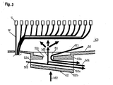
- Fig. 3 is cross sectional view for explaining one example of the conventional drain structure of the electric connection box.
- the conventional drain structure of the electric connection box K2 includes the hollow drain portion 52 which is continuous with the water discharging hole 51 formed on the bottom wall 50 of the lower case or lower cover of the electric connection box.
- the bottom wall 50 of the electric connection box is formed to downwardly incline toward the water discharging hole 51.
- the drain portion 52 has an upper surface 52a and a bottom surface 52b.
- a communication hole 52c which is continuous with lower part of the water discharging hole 51 is formed on the upper surface 52a.
- a through hole 52d for passing through the water which penetrates from the outside is formed in one edge part of the upper surface 52a and bottom surface 52b.
- a drain port 52e for draining off the water which penetrates from the outside and which penetrates through the water discharging hole 51 to the outside is formed in another edge part of the upper surface 52a and bottom surface 52b.
- the drain port 52e has vertical width greater than the through hole 52d.
- the bottom wall 52b of the drain portion 52 is formed to incline downward from the through hole 52d toward the drain port 52e.
- the water which penetrates from the outside through the through hole.52d is drained off along the bottom surface 52b of the drain portion 52 and through the drain port 52e to the outside (arrow M3).
- Patent document 1 there is proposed the drain structure of the electric connection box including a substantially funnel-shaped portion which is provided on a bottom wall of the electric connection box and whose base edge part is narrowed as going downward, a drain port including a cylindrical portion whose edge portion continuous with the substantially funnel-shaped portion has the same inner shape as the inner shape of a lowermost edge portion of the substantially funnel-shaped portion, and a reflecting member provided in the substantially funnel-shaped portion of the drain port, wherein the reflecting member includes a mortar-shaped recess portion which has a hole opening downward and is widen as going downward and a fixed flange portion which is fixed on the substantially funnel-shaped portion, and wherein a discharging portion through which moister inside the electric connection box can be discharged to the outside of the electric connection box, is provided on the fixed flange portion (hereinafter, this art is referred to as prior art 2).
- Patent document 2 there is proposed the drain structure of the electric connection box in which a drain port wall is provided to be projected from a case bottom wall of the electric connection box and a pair of waterproof lid engaging portions is provided to be faced each other and to be projected from the lower edge of the drain port wall, an engaging hook is inwardly provided to be projected from the lower edge of the waterproof engaging portion, the waterproof lid is mounted with the both edges held by the engaging hooks, and the waterproof lid is lifted up by water pressure from below and seals an opening of the lower edge of the drain port wall (hereinafter, this art is referred to as prior art 3).
- the present invention is proposed for solving these problems described above, and one of the purpose of the present invention is to provide the drain structure of the electric connection box which is capable of fully preventing penetration of water with simple structure.
- the drain structure of electrical connection box of the present invention including a hollow drain portion in which a communication hole continuous with a water discharging hole of the electric connection box and the drain port for draining off water which penetrates from the communication hole to the outside, comprising; a waterproof lid including a substantially board-shaped lid portion and a pair of engaging leg portions provided in lower part of said lid portion: wherein said pair of engaging leg portions of said waterproof lid is engaged in peripheral part of said communication hole of said drain portion, and said lid portion is provided to cover said water discharging hole.
- Said pair of engaging leg portions can be provided to be extended from the position inner than peripheral part of said lid portion in the substantially vertical direction.
- Said pair of engaging leg portions can be formed to be widen in the substantially horizontal direction.
- the pair of engaging leg portions of the waterproof lid is engaged in the peripheral part of the communication hole of the water discharging hole and the lid portion is attached to cover the upper part of the discharging port, it is possible to dam the water which penetrates through to the inside of the electric connection box through the communication hole and the water discharging hole of the drain portion with the lid portion of the waterproof lid, and to prevent the water from gushing inside the electric connection box.
- terminal portion T of wire W such as wire harness or the like which is arranged to run from moistening with the water, penetration of water can be fully prevented.
- the waterproof lid is formed apart from the lower case or lower cover and can be applied to the conventional structure, the whole structure can be simple and gives freedom to design of the electric connection box.
- the water can easily flow toward the outside without collecting on the upper surface of the lid portion, and can be easily drained off to the outside along the bottom wall of the lower case or lower cover, the water discharging hole, the communication hole of the drain portion, and the drain port.
- the contact area with the wire such as wire harness or the like which is arranged to run inside the electric connection box can be enlarged and the stress to the wire harness accompanied with vibration of the vehicle body or the like can be eased, and accordingly it is possible to prevent the wire from breaking.
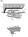
- Fig. 1 is a sectional view of the drain structure of the electrical connection box according to the embodiment of the present invention
- (B) is a sectional view of (A) taken along the line b-b
- Fig. 2 (A) is a perspective view of the waterproof lid seen from above
- (B) is a perspective view of the waterproof lid seen from below
- (C) is a front view of the waterproof lid
- (D) is a side view of the waterproof lid.
- the drain structure of the electric connection box K1 is characterized in that the waterproof lid 1 is attached to the drain portion 52 as shown in Fig. 3 .
- the waterproof lid 1 includes a lid portion 2 which is substantially board-shaped, and a pair of engaging legs provided in the lower part of the lid portion 2.
- the engaging hook 3a is formed on a pair of engaging leg portions 3a of the waterproof lid 1, and when the engaging hook 3a is engaged in the peripheral part of the communication hole 52c of the drain portion 52, the lid portion 2 is attached to cover the upper part of the water discharging hole 51.
- the upper surface of the lid portion 2 of the waterproof lid 1 is formed to downwardly incline toward the outside.
- an angle of ⁇ 1 in Fig. 2 (C) is 35 degrees
- an angle of ⁇ 2 in Fig. 2 (D) is 4 degrees
- an angle of ⁇ 3 is 10 degrees.
- these angles are expressively provided as examples and the invention is not limited to the above value.
- the water flows toward the outside without being collected on the upper surface of lid portion 2, and can be easily drained off to the outside through the lower case or lower cover of the bottom wall 50, the water discharging hole 51, the communication hole 52c of the drain portion 52, and the drain port 52e (arrow M5 in Fig. 1 (B) ).
- the waterproof lid 1 described above is provided inside the electric connection box, such a problem can be solved by the drain structure of the embodiment that when the electric connection box is downsized, the space of the inside is so insufficient that the wire harness and the waterproof lid 1 interfere with each other.
- the upper surface of the lid portion 2 is formed to downwardly incline toward the outside.
- the contact area with the wire W such as wire harness or the like, which is arranged to run, is made large so that the stress to the wire harness W accompanied by the vibration of the vehicle body or the like can be reduced, and, accordingly, it is possible to prevent the wire W from breaking.
- the pair of engaging leg portions 3 is configured to extend downward in the substantially vertical direction from the position which is located inner side of the peripheral part of the lid portion 2. Therefore, it is possible to prevent the wire W from interfering and winding around the engaging legs 3.
- the engaging legs 3 are formed to be wide in the horizontal direction of Fig. 1 (A) (in the vertical direction on the paper) and the water flows through the route shown with arrow in Fig. 1 (A) , the water hits the engaging leg portions 3 and is surely dammed and prevented from penetrating through to the inside of the electric connection box.
- the pair of engaging leg portions 3 of the waterproof lid 1 is engaged in the peripheral part of the communication hole 52c of the drain portion 52 and the lid portion 2 is provided to cover the upper part of the water discharging hole 51.
- the water which penetrates through to the inside of the electric connection box through the communication hole 52c and water discharging hole 51 of the drain portion 52 can be dammed with the use of the lid portion 2 of the waterproof lid 1 and can be prevented from gushing into the electric connection box (arrow M6 in Fig. 1(A) ).
- the terminal portion T of the wire W such as wire harness or the like which is arranged to run from moistening with the water, and the penetration of water can be surely prevented.
- the waterproof lid 1 is separately formed from the lower case or lower cover, and is applicable as it is to the conventional structure (refer to Fig. 3 ), the structure becomes simple and extends wide design choice of the electric connection box.
- the present invention is applied to various electric connection boxes incorporated in automobile or the like for draining off water which is inside the electric connection box and for preventing water from penetrating through from the outside.
Landscapes
- Engineering & Computer Science (AREA)
- Microelectronics & Electronic Packaging (AREA)
- Architecture (AREA)
- Civil Engineering (AREA)
- Structural Engineering (AREA)
- Connection Or Junction Boxes (AREA)
- Casings For Electric Apparatus (AREA)
- Connector Housings Or Holding Contact Members (AREA)
Abstract
Description
- The present invention relates to a drain structure of an electric connection box mounted on an automobile or the like, in particular, the present invention relates to a drain structure of an electric connection box for draining off water which is captured inside the electric connection box and in addition, for preventing water from penetrating from outside thereof.
- In general, in a vehicle such as an automobile or the like, the electric connection box such as a junction box, a fuse box, a relays-box or the like has been used for receiving electric parts such as wire harness connecting parts, a fuse, relays, an electronic control unit, or the like.
- Since the electric connection box is mostly located in an engine compartment or a lower side part of a vehicle body, in such cases that it heavily rains, the vehicle body is washed by the water under the high pressure, and the practical test such as a pool diving test is executed, the water can penetrates through to the inside of the electric connection box. Furthermore, there can be dew condensation and collection of water drops inside the electric connection box. In such cases that the water penetrates through or collects inside the electric connection box, there are risks that such parts as circuit are short-circuited and that electrical current leaks, and, accordingly, the above described water may causes malfunction of the operation and melting to damage the parts.
- Therefore, when the electric connection box has a lower case or lower cover, there is applied the structure in which a water discharging hole is formed on the bottom wall of the lower cover for draining off water which is inside the electric connection box to the outside through the water discharging hole in order to prevent water from collecting inside the electric connection box and to prevent water from penetrating through from the outside.
-
Fig. 3 is cross sectional view for explaining one example of the conventional drain structure of the electric connection box. - As shown in
Fig. 3 , the conventional drain structure of the electric connection box K2 includes thehollow drain portion 52 which is continuous with thewater discharging hole 51 formed on thebottom wall 50 of the lower case or lower cover of the electric connection box. - The
bottom wall 50 of the electric connection box is formed to downwardly incline toward thewater discharging hole 51. - The
drain portion 52 has anupper surface 52a and abottom surface 52b. Acommunication hole 52c which is continuous with lower part of thewater discharging hole 51 is formed on theupper surface 52a. A throughhole 52d for passing through the water which penetrates from the outside is formed in one edge part of theupper surface 52a andbottom surface 52b. Adrain port 52e for draining off the water which penetrates from the outside and which penetrates through thewater discharging hole 51 to the outside is formed in another edge part of theupper surface 52a andbottom surface 52b. - The
drain port 52e has vertical width greater than the throughhole 52d. Thebottom wall 52b of thedrain portion 52 is formed to incline downward from the throughhole 52d toward thedrain port 52e. - In the conventional drain structure of electric connection box K2, the water penetrating through to the inside of the electric connection box drops on the
bottom wall 50, collects on thewater discharging hole 51 along the inclination, passes through thecommunication hole 52c of thedrain portion 52, and is drained off from thedrain port 52e to the outside (arrow M1). - On the other hand, since the water which upwardly penetrates from the outside is dammed by the outer wall of the
drain portion 52, it is possible to prevent the water from penetrating through to the inside of the electric connection box (arrow M2). - The water which penetrates from the outside through the through hole.52d is drained off along the
bottom surface 52b of thedrain portion 52 and through thedrain port 52e to the outside (arrow M3). - Furthermore, the water which penetrates through the
drain port 52e is brought back along thebottom surface 52b of thedrain portion 52 and drained off through thedrain port 52e to the outside (arrow M4) (hereinafter, this art is referred to as prior art 1). - And in Patent document 1, there is proposed the drain structure of the electric connection box including a substantially funnel-shaped portion which is provided on a bottom wall of the electric connection box and whose base edge part is narrowed as going downward, a drain port including a cylindrical portion whose edge portion continuous with the substantially funnel-shaped portion has the same inner shape as the inner shape of a lowermost edge portion of the substantially funnel-shaped portion, and a reflecting member provided in the substantially funnel-shaped portion of the drain port, wherein the reflecting member includes a mortar-shaped recess portion which has a hole opening downward and is widen as going downward and a fixed flange portion which is fixed on the substantially funnel-shaped portion, and wherein a discharging portion through which moister inside the electric connection box can be discharged to the outside of the electric connection box, is provided on the fixed flange portion (hereinafter, this art is referred to as prior art 2).
- Furthermore, in
Patent document 2, there is proposed the drain structure of the electric connection box in which a drain port wall is provided to be projected from a case bottom wall of the electric connection box and a pair of waterproof lid engaging portions is provided to be faced each other and to be projected from the lower edge of the drain port wall, an engaging hook is inwardly provided to be projected from the lower edge of the waterproof engaging portion, the waterproof lid is mounted with the both edges held by the engaging hooks, and the waterproof lid is lifted up by water pressure from below and seals an opening of the lower edge of the drain port wall (hereinafter, this art is referred to as prior art 3). - Patent document 1: Japanese Patent Application Publication No.
2006-67709 - Patent document 2: Japanese Patent Publication No.
3052807 - In the prior art 1, when large quantity of water penetrates from the outside through the through
hole 52d or thedrain port 52e (arrow M3, M4), or force of water is considerably strong, the water splashes into the electric connection box (arrow W5) and gushes inside the electric connection box. As a result, since the terminal portion T of the wire harness W or the like which is arranged to run has been moistened with the water, the insulation defect or the corrosion has been caused. After all, there has been a problem that the penetration of water cannot be fully prevented. - Furthermore, since the structure is required in which the drain port is bent-cranked in order to prevent penetration of water, there has been a problem that the structure of the mold becomes complex so that the manufacture thereof is difficult.
- In the
prior art 2, since a bump portion needs to be formed in the drain port to install the reflecting member, there has been a problem that the structure becomes complex. - In the
prior art 3, since the drain port wall needs to be formed to movably support the waterproof lid, there has been a problem that the structure becomes complex. - The present invention is proposed for solving these problems described above, and one of the purpose of the present invention is to provide the drain structure of the electric connection box which is capable of fully preventing penetration of water with simple structure.
- The drain structure of electrical connection box of the present invention including a hollow drain portion in which a communication hole continuous with a water discharging hole of the electric connection box and the drain port for draining off water which penetrates from the communication hole to the outside, comprising; a waterproof lid including a substantially board-shaped lid portion and a pair of engaging leg portions provided in lower part of said lid portion: wherein said pair of engaging leg portions of said waterproof lid is engaged in peripheral part of said communication hole of said drain portion, and said lid portion is provided to cover said water discharging hole.
- Said pair of engaging leg portions can be provided to be extended from the position inner than peripheral part of said lid portion in the substantially vertical direction.
- Said pair of engaging leg portions can be formed to be widen in the substantially horizontal direction.
- According to the claim 1, since the pair of engaging leg portions of the waterproof lid is engaged in the peripheral part of the communication hole of the water discharging hole and the lid portion is attached to cover the upper part of the discharging port, it is possible to dam the water which penetrates through to the inside of the electric connection box through the communication hole and the water discharging hole of the drain portion with the lid portion of the waterproof lid, and to prevent the water from gushing inside the electric connection box. As a result, since it is possible to prevent terminal portion T of wire W such as wire harness or the like which is arranged to run from moistening with the water, penetration of water can be fully prevented.
- And, since the waterproof lid is formed apart from the lower case or lower cover and can be applied to the conventional structure, the whole structure can be simple and gives freedom to design of the electric connection box.
- According to the invention in
claim 2, since the upper surface of the lid portion is formed to downwardly incline toward the outside, the water can easily flow toward the outside without collecting on the upper surface of the lid portion, and can be easily drained off to the outside along the bottom wall of the lower case or lower cover, the water discharging hole, the communication hole of the drain portion, and the drain port. Further, the contact area with the wire such as wire harness or the like which is arranged to run inside the electric connection box can be enlarged and the stress to the wire harness accompanied with vibration of the vehicle body or the like can be eased, and accordingly it is possible to prevent the wire from breaking. - According to the invention in
claim 3, it is possible to prevent the wire from touching and winding around the engaging leg portions. - According to the invention in
claim 3, it is possible to prevent and surely dam the water which penetrates through to the electric connection box with the wide engaging leg portions. -
-
FIG. 1 (A) is sectional view of the drain structure of electric connection box according to the embodiment of the present invention, and (B) is sectional view of (A) taken along the line b-b -
FIG. 2 (A) is perspective view of the waterproof lid seen from above, (B) is perspective view of the waterproof lid seen from below, (C) is front view of the waterproof lid, (D) is side view of the waterproof lid -
FIG. 3 is sectional view for explaining one prior art of drain structure of electric connection box -
- K1
- drain structure of electrical connection box
- W
- wire
- 1
- waterproof lid
- 2
- lid portion
- 3
- engaging leg portion
- 3a
- engaging hook
- 50
- bottom wall
- 51
- water discharging hole
- 52
- drain portion
- The preferred embodiment of the present invention is described below with reference to the drawings.
Fig. 1 (A) is a sectional view of the drain structure of the electrical connection box according to the embodiment of the present invention, (B) is a sectional view of (A) taken along the line b-b,Fig. 2 (A) is a perspective view of the waterproof lid seen from above, (B) is a perspective view of the waterproof lid seen from below, (C) is a front view of the waterproof lid, and (D) is a side view of the waterproof lid. - As shown in
Fig. 1 , the drain structure of the electric connection box K1 according to the embodiment of the present invention is characterized in that the waterproof lid 1 is attached to thedrain portion 52 as shown inFig. 3 . - The waterproof lid 1 includes a
lid portion 2 which is substantially board-shaped, and a pair of engaging legs provided in the lower part of thelid portion 2. - The
engaging hook 3a is formed on a pair of engagingleg portions 3a of the waterproof lid 1, and when theengaging hook 3a is engaged in the peripheral part of thecommunication hole 52c of thedrain portion 52, thelid portion 2 is attached to cover the upper part of thewater discharging hole 51. - The upper surface of the
lid portion 2 of the waterproof lid 1 is formed to downwardly incline toward the outside. For example, an angle of θ1 inFig. 2 (C) is 35 degrees, an angle of θ2 inFig. 2 (D) is 4 degrees, and an angle of θ3 is 10 degrees. However, these angles are expressively provided as examples and the invention is not limited to the above value. - Since the upper surface of the
lid portion 2 is formed to downwardly incline toward the outside as described above, the water flows toward the outside without being collected on the upper surface oflid portion 2, and can be easily drained off to the outside through the lower case or lower cover of thebottom wall 50, thewater discharging hole 51, thecommunication hole 52c of thedrain portion 52, and thedrain port 52e (arrow M5 inFig. 1 (B) ). In the case that the waterproof lid 1 described above is provided inside the electric connection box, such a problem can be solved by the drain structure of the embodiment that when the electric connection box is downsized, the space of the inside is so insufficient that the wire harness and the waterproof lid 1 interfere with each other. More specifically, as described above, the upper surface of thelid portion 2 is formed to downwardly incline toward the outside. Thus, the contact area with the wire W such as wire harness or the like, which is arranged to run, is made large so that the stress to the wire harness W accompanied by the vibration of the vehicle body or the like can be reduced, and, accordingly, it is possible to prevent the wire W from breaking. - The pair of engaging
leg portions 3 is configured to extend downward in the substantially vertical direction from the position which is located inner side of the peripheral part of thelid portion 2. Therefore, it is possible to prevent the wire W from interfering and winding around the engaginglegs 3. - Furthermore, since the engaging
legs 3 are formed to be wide in the horizontal direction ofFig. 1 (A) (in the vertical direction on the paper) and the water flows through the route shown with arrow inFig. 1 (A) , the water hits theengaging leg portions 3 and is surely dammed and prevented from penetrating through to the inside of the electric connection box. - According to the drain structure of electric connection box K1 in the embodiment of the present invention, the pair of engaging
leg portions 3 of the waterproof lid 1 is engaged in the peripheral part of thecommunication hole 52c of thedrain portion 52 and thelid portion 2 is provided to cover the upper part of thewater discharging hole 51. Thus, the water which penetrates through to the inside of the electric connection box through thecommunication hole 52c andwater discharging hole 51 of thedrain portion 52, can be dammed with the use of thelid portion 2 of the waterproof lid 1 and can be prevented from gushing into the electric connection box (arrow M6 inFig. 1(A) ). As a result, it is possible to prevent the terminal portion T of the wire W such as wire harness or the like which is arranged to run from moistening with the water, and the penetration of water can be surely prevented. - Furthermore, since the waterproof lid 1 is separately formed from the lower case or lower cover, and is applicable as it is to the conventional structure (refer to
Fig. 3 ), the structure becomes simple and extends wide design choice of the electric connection box. - The present invention is not limited to the embodiment described above, but can be variously changed within the scope of the technical feature described in the claims.
- The present invention is applied to various electric connection boxes incorporated in automobile or the like for draining off water which is inside the electric connection box and for preventing water from penetrating through from the outside.
Claims (4)
- A drain structure of an electrical connection box including a hollow drain portion in which a communication hole continuous with a water water discharging hole of the electric connection box and a drain port for draining off water from said communication hole to outside are formed, comprising:a lid portion which is substantially board-shaped; anda pair of engaging leg portions which is provided in a lower part of said lid portion,wherein said pair of engaging leg portions of said waterproof lid are engaged in a peripheral part of said communication hole of said drain portion, and said lid portion is attached to cover an upper part of said water discharging hole.
- The drain structure of the electric connection box as claimed in claim 1, wherein an upper surface of said lid portion of said waterproof lid is formed to downwardly incline toward outside.
- The drain structure of the electric connection box as claimed in claim 1 or 2, wherein said pair of engaging leg portions are formed to extend downward in substantially vertical direction from a position which is located inner side of a peripheral part of said lid portion.
- The drain structure of the electric connection box as claimed in any one of claims 1 to 3, wherein said pair of leg portions is formed to be wide in substantially horizontal direction.
Applications Claiming Priority (2)
| Application Number | Priority Date | Filing Date | Title |
|---|---|---|---|
| JP2007120362A JP4413945B2 (en) | 2007-04-27 | 2007-04-27 | Electrical junction box drainage structure |
| PCT/JP2008/058147 WO2008136447A1 (en) | 2007-04-27 | 2008-04-25 | Water drainage structure for electric connection box |
Publications (3)
| Publication Number | Publication Date |
|---|---|
| EP2144344A1 true EP2144344A1 (en) | 2010-01-13 |
| EP2144344A4 EP2144344A4 (en) | 2011-06-08 |
| EP2144344B1 EP2144344B1 (en) | 2015-03-04 |
Family
ID=39943554
Family Applications (1)
| Application Number | Title | Priority Date | Filing Date |
|---|---|---|---|
| EP08752181.1A Active EP2144344B1 (en) | 2007-04-27 | 2008-04-25 | Water drainage structure for electric connection box |
Country Status (5)
| Country | Link |
|---|---|
| US (1) | US8309847B2 (en) |
| EP (1) | EP2144344B1 (en) |
| JP (1) | JP4413945B2 (en) |
| CN (1) | CN101682182B (en) |
| WO (1) | WO2008136447A1 (en) |
Cited By (2)
| Publication number | Priority date | Publication date | Assignee | Title |
|---|---|---|---|---|
| CN112821307A (en) * | 2019-11-18 | 2021-05-18 | 矢崎总业株式会社 | Liquid discharge structure |
| EP3823116A1 (en) * | 2019-11-18 | 2021-05-19 | Yazaki Corporation | Liquid discharge structure |
Families Citing this family (13)
| Publication number | Priority date | Publication date | Assignee | Title |
|---|---|---|---|---|
| JP5737590B2 (en) * | 2011-12-12 | 2015-06-17 | 株式会社オートネットワーク技術研究所 | Electric wire with terminal and terminal |
| US9549477B2 (en) | 2012-02-28 | 2017-01-17 | Telefonaktiebolaget Lm Ericsson (Publ) | Housing for electronic components |
| JP5961884B2 (en) * | 2012-06-07 | 2016-08-03 | 矢崎総業株式会社 | Electrical junction box |
| US9226418B2 (en) * | 2012-09-21 | 2015-12-29 | Thomas & Betts International, Llc | Electrical box with drip point compartments |
| JP6026250B2 (en) * | 2012-11-30 | 2016-11-16 | 矢崎総業株式会社 | Mounting structure of the electrical junction box to the body panel |
| RU2524520C1 (en) * | 2013-01-23 | 2014-07-27 | Закрытое Акционерное Общество "Мзва" | Hardware clip |
| JP6151049B2 (en) * | 2013-03-04 | 2017-06-21 | 矢崎総業株式会社 | Electrical junction box |
| JP6145771B2 (en) | 2013-06-20 | 2017-06-14 | 矢崎総業株式会社 | Wire harness |
| FR3009451B1 (en) * | 2013-08-01 | 2017-05-19 | Jean Pierre Jouve | PROTECTIVE SHEATH FOR ENTERRES CABLES AND METHOD OF USE |
| JP6253961B2 (en) * | 2013-11-25 | 2017-12-27 | 矢崎総業株式会社 | Electrical junction box |
| US10772226B2 (en) * | 2018-03-27 | 2020-09-08 | Otis Elevator Company | Waterproof cover |
| CA3115469A1 (en) | 2018-10-08 | 2020-04-16 | Hubbell Incorporated | Electrical ground box |
| CN110626431B (en) * | 2019-10-31 | 2024-06-28 | 三一汽车制造有限公司 | Sealing device, cab and vehicle |
Family Cites Families (10)
| Publication number | Priority date | Publication date | Assignee | Title |
|---|---|---|---|---|
| DE3224005A1 (en) | 1982-06-26 | 1984-01-05 | Dr. Johannes Heidenhain Gmbh, 8225 Traunreut | LENGTH OR ANGLE MEASURING SYSTEM |
| JPS63131519U (en) * | 1987-02-16 | 1988-08-29 | ||
| JPH0623086B2 (en) | 1989-07-19 | 1994-03-30 | 花王株式会社 | Cleaning composition |
| JPH0750829Y2 (en) * | 1989-08-09 | 1995-11-15 | 矢崎総業株式会社 | Electrical junction box |
| JP3052807B2 (en) | 1995-10-05 | 2000-06-19 | 住友電装株式会社 | Drainage structure of electrical junction box |
| JPH11266516A (en) * | 1998-01-16 | 1999-09-28 | Sumitomo Wiring Syst Ltd | Distribution box |
| JP2001095129A (en) * | 1999-09-22 | 2001-04-06 | Yazaki Corp | Drainage structure of electrical junction box |
| JP4032207B2 (en) * | 2000-10-11 | 2008-01-16 | スズキ株式会社 | Waterproof controller |
| DE10308669B4 (en) * | 2003-02-28 | 2006-06-08 | Daimlerchrysler Ag | Drainage arrangement for a body cavity |
| JP2006067709A (en) | 2004-08-27 | 2006-03-09 | Furukawa Electric Co Ltd:The | Drainage structure of electrical junction box |
-
2007
- 2007-04-27 JP JP2007120362A patent/JP4413945B2/en active Active
-
2008
- 2008-04-25 CN CN2008800139125A patent/CN101682182B/en active Active
- 2008-04-25 EP EP08752181.1A patent/EP2144344B1/en active Active
- 2008-04-25 WO PCT/JP2008/058147 patent/WO2008136447A1/en not_active Ceased
- 2008-04-25 US US12/597,663 patent/US8309847B2/en not_active Expired - Fee Related
Cited By (6)
| Publication number | Priority date | Publication date | Assignee | Title |
|---|---|---|---|---|
| CN112821307A (en) * | 2019-11-18 | 2021-05-18 | 矢崎总业株式会社 | Liquid discharge structure |
| EP3823117A1 (en) * | 2019-11-18 | 2021-05-19 | Yazaki Corporation | Liquid discharge structure |
| EP3823116A1 (en) * | 2019-11-18 | 2021-05-19 | Yazaki Corporation | Liquid discharge structure |
| CN112821307B (en) * | 2019-11-18 | 2022-11-29 | 矢崎总业株式会社 | liquid discharge structure |
| US11589468B2 (en) | 2019-11-18 | 2023-02-21 | Yazaki Corporation | Liquid discharge structure |
| US11791588B2 (en) | 2019-11-18 | 2023-10-17 | Yazaki Corporation | Liquid discharge structure |
Also Published As
| Publication number | Publication date |
|---|---|
| JP2008278663A (en) | 2008-11-13 |
| EP2144344B1 (en) | 2015-03-04 |
| JP4413945B2 (en) | 2010-02-10 |
| US8309847B2 (en) | 2012-11-13 |
| US20100230128A1 (en) | 2010-09-16 |
| CN101682182A (en) | 2010-03-24 |
| CN101682182B (en) | 2012-05-30 |
| EP2144344A4 (en) | 2011-06-08 |
| WO2008136447A1 (en) | 2008-11-13 |
Similar Documents
| Publication | Publication Date | Title |
|---|---|---|
| EP2144344B1 (en) | Water drainage structure for electric connection box | |
| EP2234231A1 (en) | Electric connection box | |
| US8157116B2 (en) | Electrical junction box | |
| US9374916B2 (en) | Electrical junction box | |
| US7893364B2 (en) | Electrical junction box | |
| JP4901374B2 (en) | Drainage structure of electrical junction box | |
| US6787698B2 (en) | Drainage structure of electric parts accommodation box | |
| EP2190090A1 (en) | Waterproof Box | |
| JP2005229740A (en) | Electrical connection box for automobile | |
| JPH11266516A (en) | Distribution box | |
| US9204562B2 (en) | Electrical junction box | |
| EP3795427A1 (en) | Electrical connection box and wire harness | |
| CN104242189B (en) | Electrical junction box | |
| JP2014108038A (en) | Case | |
| CN107947074A (en) | Electrical junction box and wiring harness | |
| JP2008195182A (en) | Wire harness laying structure for door | |
| JP2013219140A (en) | Electronic control unit | |
| JP2014103797A (en) | Electric connection box | |
| US9219356B2 (en) | Electrical junction box | |
| EP2772998A2 (en) | Electrical connection box | |
| JP2001095129A (en) | Drainage structure of electrical junction box | |
| CN216433370U (en) | Protective shell of electrical device and engineering machine | |
| JP2012016219A (en) | Waterproof case | |
| JP2016059225A (en) | Electric connection box | |
| JP6459909B2 (en) | Door side fixing part and wire harness |
Legal Events
| Date | Code | Title | Description |
|---|---|---|---|
| PUAI | Public reference made under article 153(3) epc to a published international application that has entered the european phase |
Free format text: ORIGINAL CODE: 0009012 |
|
| 17P | Request for examination filed |
Effective date: 20091106 |
|
| AK | Designated contracting states |
Kind code of ref document: A1 Designated state(s): AT BE BG CH CY CZ DE DK EE ES FI FR GB GR HR HU IE IS IT LI LT LU LV MC MT NL NO PL PT RO SE SI SK TR |
|
| DAX | Request for extension of the european patent (deleted) | ||
| REG | Reference to a national code |
Ref country code: DE Ref legal event code: R079 Ref document number: 602008036952 Country of ref document: DE Free format text: PREVIOUS MAIN CLASS: H02G0003160000 Ipc: H02G0003080000 |
|
| A4 | Supplementary search report drawn up and despatched |
Effective date: 20110511 |
|
| RIC1 | Information provided on ipc code assigned before grant |
Ipc: H05K 5/02 20060101ALI20110504BHEP Ipc: H02G 3/08 20060101AFI20110504BHEP |
|
| 17Q | First examination report despatched |
Effective date: 20130311 |
|
| GRAP | Despatch of communication of intention to grant a patent |
Free format text: ORIGINAL CODE: EPIDOSNIGR1 |
|
| GRAJ | Information related to disapproval of communication of intention to grant by the applicant or resumption of examination proceedings by the epo deleted |
Free format text: ORIGINAL CODE: EPIDOSDIGR1 |
|
| GRAP | Despatch of communication of intention to grant a patent |
Free format text: ORIGINAL CODE: EPIDOSNIGR1 |
|
| GRAJ | Information related to disapproval of communication of intention to grant by the applicant or resumption of examination proceedings by the epo deleted |
Free format text: ORIGINAL CODE: EPIDOSDIGR1 |
|
| GRAP | Despatch of communication of intention to grant a patent |
Free format text: ORIGINAL CODE: EPIDOSNIGR1 |
|
| INTG | Intention to grant announced |
Effective date: 20140922 |
|
| INTG | Intention to grant announced |
Effective date: 20141006 |
|
| INTG | Intention to grant announced |
Effective date: 20141015 |
|
| GRAS | Grant fee paid |
Free format text: ORIGINAL CODE: EPIDOSNIGR3 |
|
| GRAA | (expected) grant |
Free format text: ORIGINAL CODE: 0009210 |
|
| AK | Designated contracting states |
Kind code of ref document: B1 Designated state(s): AT BE BG CH CY CZ DE DK EE ES FI FR GB GR HR HU IE IS IT LI LT LU LV MC MT NL NO PL PT RO SE SI SK TR |
|
| REG | Reference to a national code |
Ref country code: GB Ref legal event code: FG4D |
|
| REG | Reference to a national code |
Ref country code: CH Ref legal event code: EP |
|
| REG | Reference to a national code |
Ref country code: IE Ref legal event code: FG4D |
|
| REG | Reference to a national code |
Ref country code: AT Ref legal event code: REF Ref document number: 714599 Country of ref document: AT Kind code of ref document: T Effective date: 20150415 |
|
| REG | Reference to a national code |
Ref country code: DE Ref legal event code: R096 Ref document number: 602008036952 Country of ref document: DE Effective date: 20150416 |
|
| REG | Reference to a national code |
Ref country code: AT Ref legal event code: MK05 Ref document number: 714599 Country of ref document: AT Kind code of ref document: T Effective date: 20150304 Ref country code: NL Ref legal event code: VDEP Effective date: 20150304 |
|
| PG25 | Lapsed in a contracting state [announced via postgrant information from national office to epo] |
Ref country code: LT Free format text: LAPSE BECAUSE OF FAILURE TO SUBMIT A TRANSLATION OF THE DESCRIPTION OR TO PAY THE FEE WITHIN THE PRESCRIBED TIME-LIMIT Effective date: 20150304 Ref country code: SE Free format text: LAPSE BECAUSE OF FAILURE TO SUBMIT A TRANSLATION OF THE DESCRIPTION OR TO PAY THE FEE WITHIN THE PRESCRIBED TIME-LIMIT Effective date: 20150304 Ref country code: NO Free format text: LAPSE BECAUSE OF FAILURE TO SUBMIT A TRANSLATION OF THE DESCRIPTION OR TO PAY THE FEE WITHIN THE PRESCRIBED TIME-LIMIT Effective date: 20150604 Ref country code: ES Free format text: LAPSE BECAUSE OF FAILURE TO SUBMIT A TRANSLATION OF THE DESCRIPTION OR TO PAY THE FEE WITHIN THE PRESCRIBED TIME-LIMIT Effective date: 20150304 Ref country code: FI Free format text: LAPSE BECAUSE OF FAILURE TO SUBMIT A TRANSLATION OF THE DESCRIPTION OR TO PAY THE FEE WITHIN THE PRESCRIBED TIME-LIMIT Effective date: 20150304 Ref country code: HR Free format text: LAPSE BECAUSE OF FAILURE TO SUBMIT A TRANSLATION OF THE DESCRIPTION OR TO PAY THE FEE WITHIN THE PRESCRIBED TIME-LIMIT Effective date: 20150304 |
|
| REG | Reference to a national code |
Ref country code: LT Ref legal event code: MG4D |
|
| PG25 | Lapsed in a contracting state [announced via postgrant information from national office to epo] |
Ref country code: LV Free format text: LAPSE BECAUSE OF FAILURE TO SUBMIT A TRANSLATION OF THE DESCRIPTION OR TO PAY THE FEE WITHIN THE PRESCRIBED TIME-LIMIT Effective date: 20150304 Ref country code: GR Free format text: LAPSE BECAUSE OF FAILURE TO SUBMIT A TRANSLATION OF THE DESCRIPTION OR TO PAY THE FEE WITHIN THE PRESCRIBED TIME-LIMIT Effective date: 20150605 Ref country code: AT Free format text: LAPSE BECAUSE OF FAILURE TO SUBMIT A TRANSLATION OF THE DESCRIPTION OR TO PAY THE FEE WITHIN THE PRESCRIBED TIME-LIMIT Effective date: 20150304 |
|
| PG25 | Lapsed in a contracting state [announced via postgrant information from national office to epo] |
Ref country code: NL Free format text: LAPSE BECAUSE OF FAILURE TO SUBMIT A TRANSLATION OF THE DESCRIPTION OR TO PAY THE FEE WITHIN THE PRESCRIBED TIME-LIMIT Effective date: 20150304 |
|
| PG25 | Lapsed in a contracting state [announced via postgrant information from national office to epo] |
Ref country code: RO Free format text: LAPSE BECAUSE OF FAILURE TO SUBMIT A TRANSLATION OF THE DESCRIPTION OR TO PAY THE FEE WITHIN THE PRESCRIBED TIME-LIMIT Effective date: 20150304 Ref country code: PT Free format text: LAPSE BECAUSE OF FAILURE TO SUBMIT A TRANSLATION OF THE DESCRIPTION OR TO PAY THE FEE WITHIN THE PRESCRIBED TIME-LIMIT Effective date: 20150706 Ref country code: EE Free format text: LAPSE BECAUSE OF FAILURE TO SUBMIT A TRANSLATION OF THE DESCRIPTION OR TO PAY THE FEE WITHIN THE PRESCRIBED TIME-LIMIT Effective date: 20150304 Ref country code: SK Free format text: LAPSE BECAUSE OF FAILURE TO SUBMIT A TRANSLATION OF THE DESCRIPTION OR TO PAY THE FEE WITHIN THE PRESCRIBED TIME-LIMIT Effective date: 20150304 Ref country code: CZ Free format text: LAPSE BECAUSE OF FAILURE TO SUBMIT A TRANSLATION OF THE DESCRIPTION OR TO PAY THE FEE WITHIN THE PRESCRIBED TIME-LIMIT Effective date: 20150304 |
|
| PG25 | Lapsed in a contracting state [announced via postgrant information from national office to epo] |
Ref country code: PL Free format text: LAPSE BECAUSE OF FAILURE TO SUBMIT A TRANSLATION OF THE DESCRIPTION OR TO PAY THE FEE WITHIN THE PRESCRIBED TIME-LIMIT Effective date: 20150304 Ref country code: MC Free format text: LAPSE BECAUSE OF FAILURE TO SUBMIT A TRANSLATION OF THE DESCRIPTION OR TO PAY THE FEE WITHIN THE PRESCRIBED TIME-LIMIT Effective date: 20150304 Ref country code: IS Free format text: LAPSE BECAUSE OF FAILURE TO SUBMIT A TRANSLATION OF THE DESCRIPTION OR TO PAY THE FEE WITHIN THE PRESCRIBED TIME-LIMIT Effective date: 20150704 |
|
| REG | Reference to a national code |
Ref country code: CH Ref legal event code: PL |
|
| REG | Reference to a national code |
Ref country code: DE Ref legal event code: R097 Ref document number: 602008036952 Country of ref document: DE |
|
| PG25 | Lapsed in a contracting state [announced via postgrant information from national office to epo] |
Ref country code: IT Free format text: LAPSE BECAUSE OF FAILURE TO SUBMIT A TRANSLATION OF THE DESCRIPTION OR TO PAY THE FEE WITHIN THE PRESCRIBED TIME-LIMIT Effective date: 20150304 |
|
| PLBE | No opposition filed within time limit |
Free format text: ORIGINAL CODE: 0009261 |
|
| STAA | Information on the status of an ep patent application or granted ep patent |
Free format text: STATUS: NO OPPOSITION FILED WITHIN TIME LIMIT |
|
| REG | Reference to a national code |
Ref country code: IE Ref legal event code: MM4A |
|
| PG25 | Lapsed in a contracting state [announced via postgrant information from national office to epo] |
Ref country code: CH Free format text: LAPSE BECAUSE OF NON-PAYMENT OF DUE FEES Effective date: 20150430 Ref country code: LI Free format text: LAPSE BECAUSE OF NON-PAYMENT OF DUE FEES Effective date: 20150430 Ref country code: DK Free format text: LAPSE BECAUSE OF FAILURE TO SUBMIT A TRANSLATION OF THE DESCRIPTION OR TO PAY THE FEE WITHIN THE PRESCRIBED TIME-LIMIT Effective date: 20150304 |
|
| REG | Reference to a national code |
Ref country code: FR Ref legal event code: ST Effective date: 20151231 |
|
| 26N | No opposition filed |
Effective date: 20151207 |
|
| GBPC | Gb: european patent ceased through non-payment of renewal fee |
Effective date: 20150604 |
|
| PG25 | Lapsed in a contracting state [announced via postgrant information from national office to epo] |
Ref country code: FR Free format text: LAPSE BECAUSE OF NON-PAYMENT OF DUE FEES Effective date: 20150504 Ref country code: SI Free format text: LAPSE BECAUSE OF FAILURE TO SUBMIT A TRANSLATION OF THE DESCRIPTION OR TO PAY THE FEE WITHIN THE PRESCRIBED TIME-LIMIT Effective date: 20150304 |
|
| PG25 | Lapsed in a contracting state [announced via postgrant information from national office to epo] |
Ref country code: GB Free format text: LAPSE BECAUSE OF NON-PAYMENT OF DUE FEES Effective date: 20150604 Ref country code: IE Free format text: LAPSE BECAUSE OF NON-PAYMENT OF DUE FEES Effective date: 20150425 |
|
| PG25 | Lapsed in a contracting state [announced via postgrant information from national office to epo] |
Ref country code: BE Free format text: LAPSE BECAUSE OF FAILURE TO SUBMIT A TRANSLATION OF THE DESCRIPTION OR TO PAY THE FEE WITHIN THE PRESCRIBED TIME-LIMIT Effective date: 20150304 |
|
| PG25 | Lapsed in a contracting state [announced via postgrant information from national office to epo] |
Ref country code: MT Free format text: LAPSE BECAUSE OF FAILURE TO SUBMIT A TRANSLATION OF THE DESCRIPTION OR TO PAY THE FEE WITHIN THE PRESCRIBED TIME-LIMIT Effective date: 20150304 |
|
| PG25 | Lapsed in a contracting state [announced via postgrant information from national office to epo] |
Ref country code: HU Free format text: LAPSE BECAUSE OF FAILURE TO SUBMIT A TRANSLATION OF THE DESCRIPTION OR TO PAY THE FEE WITHIN THE PRESCRIBED TIME-LIMIT; INVALID AB INITIO Effective date: 20080425 Ref country code: BG Free format text: LAPSE BECAUSE OF FAILURE TO SUBMIT A TRANSLATION OF THE DESCRIPTION OR TO PAY THE FEE WITHIN THE PRESCRIBED TIME-LIMIT Effective date: 20150304 |
|
| PG25 | Lapsed in a contracting state [announced via postgrant information from national office to epo] |
Ref country code: CY Free format text: LAPSE BECAUSE OF FAILURE TO SUBMIT A TRANSLATION OF THE DESCRIPTION OR TO PAY THE FEE WITHIN THE PRESCRIBED TIME-LIMIT Effective date: 20150304 |
|
| PG25 | Lapsed in a contracting state [announced via postgrant information from national office to epo] |
Ref country code: TR Free format text: LAPSE BECAUSE OF FAILURE TO SUBMIT A TRANSLATION OF THE DESCRIPTION OR TO PAY THE FEE WITHIN THE PRESCRIBED TIME-LIMIT Effective date: 20150304 |
|
| PG25 | Lapsed in a contracting state [announced via postgrant information from national office to epo] |
Ref country code: LU Free format text: LAPSE BECAUSE OF NON-PAYMENT OF DUE FEES Effective date: 20150425 |
|
| P01 | Opt-out of the competence of the unified patent court (upc) registered |
Effective date: 20230512 |
|
| PGFP | Annual fee paid to national office [announced via postgrant information from national office to epo] |
Ref country code: DE Payment date: 20250305 Year of fee payment: 18 |