EP2144341A2 - Brushless slip ring for a wind turbine and method of assembly - Google Patents
Brushless slip ring for a wind turbine and method of assembly Download PDFInfo
- Publication number
- EP2144341A2 EP2144341A2 EP09163671A EP09163671A EP2144341A2 EP 2144341 A2 EP2144341 A2 EP 2144341A2 EP 09163671 A EP09163671 A EP 09163671A EP 09163671 A EP09163671 A EP 09163671A EP 2144341 A2 EP2144341 A2 EP 2144341A2
- Authority
- EP
- European Patent Office
- Prior art keywords
- conductive
- rotating member
- slip ring
- semi
- solid material
- Prior art date
- Legal status (The legal status is an assumption and is not a legal conclusion. Google has not performed a legal analysis and makes no representation as to the accuracy of the status listed.)
- Granted
Links
Images


Classifications
-
- H—ELECTRICITY
- H02—GENERATION; CONVERSION OR DISTRIBUTION OF ELECTRIC POWER
- H02K—DYNAMO-ELECTRIC MACHINES
- H02K13/00—Structural associations of current collectors with motors or generators, e.g. brush mounting plates or connections to windings; Disposition of current collectors in motors or generators; Arrangements for improving commutation
- H02K13/003—Structural associations of slip-rings
-
- H—ELECTRICITY
- H01—ELECTRIC ELEMENTS
- H01R—ELECTRICALLY-CONDUCTIVE CONNECTIONS; STRUCTURAL ASSOCIATIONS OF A PLURALITY OF MUTUALLY-INSULATED ELECTRICAL CONNECTING ELEMENTS; COUPLING DEVICES; CURRENT COLLECTORS
- H01R39/00—Rotary current collectors, distributors or interrupters
- H01R39/64—Devices for uninterrupted current collection
- H01R39/646—Devices for uninterrupted current collection through an electrical conductive fluid
-
- F—MECHANICAL ENGINEERING; LIGHTING; HEATING; WEAPONS; BLASTING
- F05—INDEXING SCHEMES RELATING TO ENGINES OR PUMPS IN VARIOUS SUBCLASSES OF CLASSES F01-F04
- F05B—INDEXING SCHEME RELATING TO WIND, SPRING, WEIGHT, INERTIA OR LIKE MOTORS, TO MACHINES OR ENGINES FOR LIQUIDS COVERED BY SUBCLASSES F03B, F03D AND F03G
- F05B2220/00—Application
- F05B2220/70—Application in combination with
- F05B2220/706—Application in combination with an electrical generator
- F05B2220/7066—Application in combination with an electrical generator via a direct connection, i.e. a gearless transmission
-
- Y—GENERAL TAGGING OF NEW TECHNOLOGICAL DEVELOPMENTS; GENERAL TAGGING OF CROSS-SECTIONAL TECHNOLOGIES SPANNING OVER SEVERAL SECTIONS OF THE IPC; TECHNICAL SUBJECTS COVERED BY FORMER USPC CROSS-REFERENCE ART COLLECTIONS [XRACs] AND DIGESTS
- Y02—TECHNOLOGIES OR APPLICATIONS FOR MITIGATION OR ADAPTATION AGAINST CLIMATE CHANGE
- Y02E—REDUCTION OF GREENHOUSE GAS [GHG] EMISSIONS, RELATED TO ENERGY GENERATION, TRANSMISSION OR DISTRIBUTION
- Y02E10/00—Energy generation through renewable energy sources
- Y02E10/70—Wind energy
- Y02E10/72—Wind turbines with rotation axis in wind direction
-
- Y—GENERAL TAGGING OF NEW TECHNOLOGICAL DEVELOPMENTS; GENERAL TAGGING OF CROSS-SECTIONAL TECHNOLOGIES SPANNING OVER SEVERAL SECTIONS OF THE IPC; TECHNICAL SUBJECTS COVERED BY FORMER USPC CROSS-REFERENCE ART COLLECTIONS [XRACs] AND DIGESTS
- Y10—TECHNICAL SUBJECTS COVERED BY FORMER USPC
- Y10T—TECHNICAL SUBJECTS COVERED BY FORMER US CLASSIFICATION
- Y10T29/00—Metal working
- Y10T29/49—Method of mechanical manufacture
- Y10T29/49002—Electrical device making
- Y10T29/49009—Dynamoelectric machine
- Y10T29/49011—Commutator or slip ring assembly
Definitions
- the present disclosure relates generally to generators, and more particularly to slip rings used with wind turbine generators to transfer electrical current.
- known wind turbines include a rotor having multiple blades.
- the rotor is mounted to a housing or nacelle that is positioned on top of a truss or tubular tower.
- Utility grade wind turbines i.e., wind turbines designed to provide electrical power to a utility grid
- Blades on rotors transform wind energy into a rotational torque or force that drives one or more generators that may be rotationally coupled to the rotor either directly or through a gearbox.
- the gearbox increases or steps up the inherently low rotational speed of the turbine rotor for the generator to efficiently convert mechanical energy to electrical energy, which is then transmitted to a utility grid.
- Wind turbines including direct drive generators eliminate the gearbox, and reliability problems associated with the gearboxes.
- the slip rings used to transfer electrical current from a rotating shaft to a stationary member may prematurely fail.
- Known slip rings generally use a brush assembly to transfer the electrical current.
- Such brush assemblies wear over time and generally require periodic replacement. The replacement of the brush assemblies increases the operational costs associated with the wind turbine. In some instances, replacement of the brush assemblies may require the wind turbine to be offline in a non-productive and non-operational state.
- At least some known slip ring assemblies use mercury to transfer electrical current across the slip ring assembly. Although somewhat useful, the inclusion of mercury may adversely affect the manufacturing, distribution, operation and maintenance of the slip rings because mercury is toxic, and is a hazardous material that requires special handling.
- a brushless slip ring in one aspect according to the present invention, includes a first conductive rotating member and a second conductive non-rotating member positioned a predetermined distance away from the first conductive rotating member.
- a conductive semi-solid material electrically couples the first conductive rotating member to the second conductive non-rotating member.
- the semi-solid material is configured to transfer electric current from the rotating member to the non-rotating member.
- a wind turbine in another aspect, includes a structural base and a wind driven power generator supported by the structural base.
- the wind turbine has a rotating shaft and at least one rotatable blade extending from the rotating shaft.
- the generator further includes at least one brushless slip ring coupled therein.
- the brushless slip ring includes a first conductive rotating member, a second conductive non-rotating member, and a conductive semi-solid material.
- the second conductive non-rotating member is coupled to the first conductive rotating member via the conductive semi-solid material such that the first member is a predetermined distance from the second member.
- the semi-solid material is configured to transfer electric current from the rotating member to the non-rotating member.
- a method of assembling a brushless slip ring includes coupling a first conductive rotating member about a rotatable shaft, and electrically coupling a second conductive non-rotating member to the first member using a conductive semi-solid material such that the first member is a predetermined distance away from the second member. Transferring electric current from the rotating member to the non-rotating member using the semi-solid material.
- a wind turbine 100 includes a nacelle 102 that houses a generator (not shown in Figure 1 ).
- nacelle 102 is coupled atop a tall tower 104, only a portion of which is shown in Figure 1 .
- Wind turbine 100 also includes a rotor 106 that includes one or more rotor blades 108 coupled to a rotating hub 110.
- wind turbine 100 illustrated in Figure 1 includes three rotor blades 108, there are no specific limits on the number of rotor blades 108 required by embodiments of the present invention.
- various components are housed in nacelle 102 atop tower 104 (shown in Figure 1 ) of wind turbine 100 (shown in Figure 1 ).
- a height (not shown) of tower 104 is selected based upon factors and conditions known in the art.
- one or more microcontrollers (not shown) within control panel 212 include a control system used for overall system monitoring and control of the wind turbine. Alternative distributed or centralized control architectures may be used in some configurations.
- a variable blade pitch drive 214 is provided to control a pitch of blades 108 (shown in Figure 1 ) substantially simultaneously based on a direction of wind.
- the pitches of blades 108 are individually controlled by blade pitch drive 214.
- the drive train of wind turbine 100 includes a main rotor shaft 216, also referred to as a "low speed shaft", coupled to hub 110 via main bearing 230 at a first end and 216a, in some configurations, at an opposite end 216b of shaft 216 to a gear box 218.
- Gear box 218 drives a high speed shaft (not shown in Figure 2 ) of an electrical power generator 220.
- main rotor shaft 216 is coupled directly to generator 220.
- the high speed shaft is used to drive generator 220.
- Generator 220 is mounted on main frame 232.
- rotor torque is transmitted via coupling 222.
- generator 220 is a direct drive permanent magnet generator.
- yaw drive 224 and yaw deck 226 provide a yaw orientation system for wind turbine 100.
- a meterological boom 228 provides information for a turbine control system that includes a yaw orientation system.
- the meterological boom 228 may include instrumentation sensors for wind direction and/or wind speed.
- the yaw orientation system is mounted atop tower 104.
- Figure 3 is a side cut-away view of an exemplary embodiment direct drive wind turbine 300.
- wind turbine 300 includes rotor 106, a nacelle 302, a slip ring 304, an insulation tube 308 fabricated from insulation material, an insulation layer 308, and tower 104.
- nacelle 302 includes a direct drive generator 310, a plurality of bearings 312, a rotary shaft 316, and control panel 212.
- direct drive wind turbine 300 does not include gear box 218.
- Insulation tube 306 is fabricated from an insulation material.
- Insulation layer 308 extends between hub 110 and direct drive generator 310 to electrically isolate generator 310 from hub 110.
- Insulation layer 308 also extends between bearing 312 and hub 110 to electrically isolate bearing 312 from hub 110.
- insulation layer 308 is formed across a face 314 of bearing 312 and across a face 318 of generator 310. Faces 314 and 318 are oriented to face hub 110.
- Slip ring 304 is mounted on insulation tube 306, and rotary shaft 316 circumscribes insulation tube 306 and is substantially concentric with insulation tube 306. Insulation tube 306 extends from hub 110 to tower 104. Slip ring 304 is coupled to a conductor within insulation tube 306.
- Direct drive wind turbine 300 uses rotor 106 and rotary shaft 316 to directly drive generator 310.
- Rotary shaft 316 rotates with rotor 106 and rotary shaft 316 is supported by a plurality of bearings, such as bearing 312 coupled to insulation tube 306. The bearings enabled rotary shaft 316 to rotate with respect to insulation tube 316.
- Direct drive wind turbine 300 has a variable-speed configuration and uses control panel 212, to control wind turbine 300 and direct drive generator 310.
- control panel 212 may also convert a variable-voltage, variable-frequency power of direct drive generator 310 to a standard utility voltage and frequency. Rotational energy of rotor blade 108 is transferred via hub 110 to direct drive generator 310 that correspondingly uses the rotational energy to produce electricity.
- FIG 4 illustrates a cross-sectional schematic view of an exemplary brushless slip ring 400 that may be used with the gear box wind turbine configuration (shown in Figure 2 ) and the direct drive wind turbine configuration (shown in Figure 3 ).
- Slip rings 400 are used to transfer electrical current and/or data signals from a rotating shaft to an adjacent stationary member as described in more detail below.
- the following description of a brushless slip ring is applicable to both wind turbine configurations, as well as to other implementations wherein it is required to transfer electrical current or signals from a rotating member to an adjacent stationary member.
- a brushless slip ring 400 includes a housing 402 that circumscribes a rotatable shaft 404.
- Shaft 404 rotates about an axial centerline 406.
- One or more rotating electrical elements 408 are coupled to rotatable shaft 404.
- at least one non-conductive sleeve 410 circumscribes shaft 404.
- At least one conductive rotating member 412 extends radially outward from sleeve 410 at least partially into a cavity 414 defined within housing 402.
- a conductive non-rotating member 416 is positioned within cavity 414, is electrically isolated from the cavity 414 by insulating material 415 and is spaced a predetermined distance away from rotating member 412.
- Cavity 414 also contains a conductive semi-solid material 418 that electrically couples rotating member 412 to non-rotating member 416.
- One or more cavity seals 420 are coupled between housing 402 and sleeve 410, such that material 418 within cavity 414 is electrically isolated from rotatable shaft 404 and any adjacent cavity remote from cavity 414.
- housing 402 is annular and is formed with a center aperture 423 that is substantially concentric with centerline 406. Housing 402 also includes an internal circumferential cavity 414 formed therein. Housing 402 may be fabricated from one or more several known manufacturing processes such as, but not limited to, casting, machining, injection molding, thermal forming, extruding and/or any other techniques recognized by those of ordinary skill in the art. Many suitable materials may be used to fabricate housing 402 as determined by the particular manufacturing process implemented. For example, in an embodiment, housing 402 may be injection molded using a polymer compound. Housing 402 may be transparent or translucent, such that an amount or level of the conductive semi-solid material 418 within cavity 414may be determined by external visual inspection.
- housing 402 includes one or more externally accessible ports 422 formed or fitted therein.
- Each port 422 may be used to fill cavity 414 with conductive semi-solid material 418 during manufacture, and/or to facilitate inspection and maintenance procedures. Additionally, ports 422 can be used to vent or purge cavity 414 of excess air during operation.
- Shaft 404 extends through housing 402 and is rotatable about centerline 406.
- Shaft 404 includes one or more rotating electrical elements 408 that rotate with shaft 404.
- rotating electrical element 408 may be an armature for a generator or electric motor.
- At least one non-conductive sleeve 410 is coupled to, and rotates with, shaft 404.
- Sleeve 410 is positioned within aperture 423 and engages one or more seals 420, such that cavity 414 is defined between housing 402 and sleeve 410.
- Seals 420 may be either a stationary type seal that is coupled to housing 402 and that enables shaft 402 and sleeve 410 to rotate therein, or seals 420 may be a dynamic-type seal that facilitates increasing sealing during operation by exploiting the rotational forces of brushless slip ring 400.
- Sleeve 410 may be fabricated using any several known manufacturing processes such as, but not limited to, casting, machining, injection molding, thermal forming, extruding and/or any other techniques recognized by those of ordinary skill in the art. Many suitable materials may be used to fabricate non-conductive sleeve 410, such as, but not limited to, plastic, nylon, and/or any other non-conductive material as required by the particular manufacturing process implemented.
- At least one conductive rotating member 412 extends generally radially from the non-conductive sleeve 410 into cavity 414.
- Rotating member 412 and member 416 are each fabricated from a conductive material that enables the flow electricity therethrough.
- member 412 may be fabricated from, but not limited to, copper, brass, steel, and/or aluminum.
- conductive rotating member 412 is a torus that circumscribes non-conductive sleeve 410 and extends radially into cavity 414.
- conductive rotating member 412 may have any other shape that enables slip ring 400 to function as described herein.
- member 412 may be fabricated from or include wedge-shaped portions that are spaced about sleeve 410.
- member 412 may be semi-circular and/or included a plurality of apertures or openings that enable the conductive semi-solid material to flow therethrough.
- member 412 also includes a plurality of fins or veins 424 that extend outwardly from a front surface 412a and/or a rear surface 412b of member 412. The use of fins 424 increases an amount of surface area in contact with the conductive semi-solid material 418 and thereby facilitates increasing the overall electrical current that can be transferred through slip ring 400.
- Rotating member 412 is electrically coupled to one or more rotating electrical elements 408 via one or more electrical conductors 424.
- Electrical conductors 424 may be coupled to an input, output or any combination thereof, of the rotating electrical element 408.
- Each of electrical conductors 424 extend through non-conductive sleeve 410 and isolate electrical current flowing through conductor 424 from rotatable shaft 404.
- non-rotating member 416 is positioned within cavity 414 of housing 402 such that member 416 substantially conforms to an inner surface of cavity 414.
- conductive non-rotating member 416 only partially conforms to a portion of cavity inner surface.
- conductive non-rotating member 416 is positioned near, and proximate to, conductive rotating member 412, such that a gap 417 is defined between members 412 and 416 and such that members 412 and 416 are not in physical contact with each other.
- non-rotating member 416 is electrically isolated from the inner surface of cavity 414 by positioning an insulating material 415 between member 416 and inner surface of cavity 414.
- the insulating material 415 may be any non-conductive material such as rubber, nylon, ceramic or other materials that prevent the flow of electrical current therethrough.
- the configuration of the brushless slip ring described above is inverted such that the shaft has a cavity and the housing has a conductor that extends into the cavity.
- the rotatable shaft may be structurally configured to define an annular housing that includes a cavity therein.
- a first conductive member is coupled to an external housing and extends into the cavity formed in the rotatable shaft.
- a second conductive member is positioned within the cavity and rotates with the shaft.
- a conductive semi-solid material is contained within the cavity and electrically couples the first and second conductive members.
- Non-rotating member 416 is electrically coupled to one or more stationary power supplies 426 via at least one electrical conductor 424. Additionally, non-rotating member 416 may be electrically coupled to at least one stationary energy storage 428 via at least one electrical conductor 424. As such, electrical conductors 424 may be coupled to an input, an output and/or any combination thereof of the stationary power supplies/energy storage devices 426 and 428, respectively. Electrical conductors 424 extend through housing 402 via an aperture or channel formed in housing 402. Alternatively, non-rotating member 416 and electrical conductors 424 may be integrally formed within housing 402.
- power supplies 426 and energy storage devices 428 may be combined into one device such as a power management system 430.
- the power management system 430 may be configured to provide additional functionality such as a reversible a power supply and power consumer. Additionally, the power management system 430 may also incorporate one or more data signals for operational use of power generating wind turbine 100.
- Semi-solid material 418 is contained between the conductive non-rotating and rotating members 416 and 412, respectively and provides electrical coupling there between.
- semi-solid material 418 is a grease that has been impregnated or filled with a metallic material. Material 418 enables electrical current to flow from rotating member 412 to non-rotating member 416 when member 412 is rotating with respect to member 416.
- Material 418 may be one of several known compounds such as, but not limited to, silver-filled grease, copper-filled grease, and/or iron-filled grease.
- semi-solid material 418 is described a grease, it is contemplated that a high viscosity metal-impregnated fluid may be used such as, but not limited to, a silver, copper, alloy, and/or iron-filled hypoid gear oil. It is also contemplated that semi-solid material 418 may be a conductive oil or a conductive powder that enables electric current flow therethrough.
- the conductive power may be, but not limited to, a graphite powder, a charcoal powder or a powder consisting of conductive micro-spheres.
- the conductive semi-solid material 418 substantially retains its form at standard temperature and pressure.
- One exemplary conductive semi-solid material is silver filled grease commercially available from SPI Supplies of West Chester, Pennsylvania.
- the conductive semi-solid material 418 only partially fills cavity 414 such that material 418 has room to thermally expand within cavity 414.
- material 418 substantially fills cavity 414 such that the volume of semi-solid material 418 is approximately equal to a volume of cavity 414.
- the housing 402 may be flexible such that the housing 402 can partially expand to accommodate thermal expansion of material 418.
- the extent to which cavity 414 is filled with conductive semi-solid material 418 may be determined by the particular installation and operating conditions of the brushless slip ring.
- a plurality of brushless slip rings 400 may be used in cooperation to provide increased functionality as required by various installations and operating conditions.
- a pair of brushless slip rings 400 may be combined; wherein a first supplies an initialization voltage to an armature of a power generator, and wherein a second for receives the output power from the armature.
- a further example provides multiple brushless slip rings 400 for use in a multi-phase power system, such as 3 brushless slip rings for use in a 3 phase power system.
- multiple brushless slip rings may be used in an instrumentation system for transferring multiple data signals from a moving member to a non-moving member.
- conductive rotating member 412 and conductive non-rotating member 416 may be oriented for linear motion there between.
- rotating member 412 be slidably coupled to conductive non-moving member 416.
- a conductive semi-solid material is contained within a cavity formed between the moving and non-moving members and electrically couples the members.
- FIG. 1 Another exemplary embodiment provides a brushless slip ring that includes two rotating conductive members. It is contemplated that the second conductive member coupled to the housing may rotate with the housing. In this embodiment, the housing and the shaft may both rotate with respect to each other and may rotate at different rotational speeds. The rotating housing and shaft may rotate in the same direction, in opposing directions or combinations thereof.
- an exemplary embodiment of the brushless slip ring is installed in a larger dynamic system such as a crane, a robotic assembly, or other equipment using multiple moving components.
- the housing and second conductor may be non-rotatable with respect to the rotatable shaft and first conductor, however the housing and shaft may move, translate or rotate with the components of the larger dynamic system.
- brushless slip ring described herein provides an improved and efficient means for conducting electrical signals and/or electrical power from a rotating member to a stationary member or in the alternative, from a first moving member to a second moving member.
- the brushless slip ring uses a conductive semi-solid material contained within a housing cavity, wherein a rotatable shaft having a first conductive member may rotate with respect to a second conductive member positioned within the housing and electrical current and/or signals may be transferred between the two conductive members.
- Exemplary embodiments of the brushless slip ring and methods of transferring current are described above in detail.
- the methods and the apparatus are not limited to the specific embodiments described herein nor to the specific components being used or assembled, but rather, the brushless slip ring described herein may be utilized independently and separately from other components and systems described herein or to other devices not described herein.
- other turbine components can also utilize the brushless slip ring described herein such as an instrumentation system measuring performance parameters of a rotating shaft.
- the shaft may be stationary and the housing configured to rotate around the shaft.
Abstract
Description
- The present disclosure relates generally to generators, and more particularly to slip rings used with wind turbine generators to transfer electrical current.
- As energy prices have increased, wind turbines have received increased attention as environmentally safe and relatively inexpensive alternative energy sources. With this growing interest, considerable efforts have been made to develop wind turbines that are reliable and efficient.
- Generally, known wind turbines include a rotor having multiple blades. The rotor is mounted to a housing or nacelle that is positioned on top of a truss or tubular tower. Utility grade wind turbines (i.e., wind turbines designed to provide electrical power to a utility grid) can have large rotors (e.g., 30 or more meters in diameter). Blades on rotors transform wind energy into a rotational torque or force that drives one or more generators that may be rotationally coupled to the rotor either directly or through a gearbox. The gearbox increases or steps up the inherently low rotational speed of the turbine rotor for the generator to efficiently convert mechanical energy to electrical energy, which is then transmitted to a utility grid.
- Wind turbines including direct drive generators eliminate the gearbox, and reliability problems associated with the gearboxes. However, in at least some known direct drive or geared wind turbines, the slip rings used to transfer electrical current from a rotating shaft to a stationary member may prematurely fail. Known slip rings generally use a brush assembly to transfer the electrical current. However, such brush assemblies wear over time and generally require periodic replacement. The replacement of the brush assemblies increases the operational costs associated with the wind turbine. In some instances, replacement of the brush assemblies may require the wind turbine to be offline in a non-productive and non-operational state.
- Additionally, at least some known slip ring assemblies, use mercury to transfer electrical current across the slip ring assembly. Although somewhat useful, the inclusion of mercury may adversely affect the manufacturing, distribution, operation and maintenance of the slip rings because mercury is toxic, and is a hazardous material that requires special handling.
- In one aspect according to the present invention, a brushless slip ring is provided. The brushless slip ring includes a first conductive rotating member and a second conductive non-rotating member positioned a predetermined distance away from the first conductive rotating member. A conductive semi-solid material electrically couples the first conductive rotating member to the second conductive non-rotating member. The semi-solid material is configured to transfer electric current from the rotating member to the non-rotating member.
- In another aspect, a wind turbine is provided. The wind turbine includes a structural base and a wind driven power generator supported by the structural base. The wind turbine has a rotating shaft and at least one rotatable blade extending from the rotating shaft. The generator further includes at least one brushless slip ring coupled therein. The brushless slip ring includes a first conductive rotating member, a second conductive non-rotating member, and a conductive semi-solid material. The second conductive non-rotating member is coupled to the first conductive rotating member via the conductive semi-solid material such that the first member is a predetermined distance from the second member. The semi-solid material is configured to transfer electric current from the rotating member to the non-rotating member.
- In a further aspect, a method of assembling a brushless slip ring is provided. The method includes coupling a first conductive rotating member about a rotatable shaft, and electrically coupling a second conductive non-rotating member to the first member using a conductive semi-solid material such that the first member is a predetermined distance away from the second member. Transferring electric current from the rotating member to the non-rotating member using the semi-solid material.
- It will thus be observed that various configurations of the present invention provide wind turbines with brushless slip rings that have increased operational durability.
- Moreover, some configurations of the present invention will also be observed to provide other advantages, such as increased wind turbine productivity.
- Various aspects and embodiments of the present invention will now be described in connection with the accompanying drawings, in which:
-
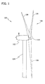
Figure 1 is a side schematic view an exemplary wind turbine. -
Figure 2 is a cut-away perspective view of a nacelle that may be used with the wind turbine shown inFigure 1 and including a geared drive train coupled to a generator. -
Figure 3 is a side cut-away view of an exemplary direct drive wind turbine generator configuration. -
Figure 4 is a cross-sectional schematic view of an exemplary brushless slip ring that may be used with the wind turbine configurations shown inFigures 2 and3 . - In some configurations and referring to
Figure 1 , awind turbine 100 includes anacelle 102 that houses a generator (not shown inFigure 1 ). In an exemplary embodiment,nacelle 102 is coupled atop atall tower 104, only a portion of which is shown inFigure 1 .Wind turbine 100 also includes arotor 106 that includes one ormore rotor blades 108 coupled to a rotatinghub 110. Althoughwind turbine 100 illustrated inFigure 1 includes threerotor blades 108, there are no specific limits on the number ofrotor blades 108 required by embodiments of the present invention. - In some configurations and referring to
Figure 2 , various components are housed innacelle 102 atop tower 104 (shown inFigure 1 ) of wind turbine 100 (shown inFigure 1 ). A height (not shown) oftower 104 is selected based upon factors and conditions known in the art. In some configurations, one or more microcontrollers (not shown) withincontrol panel 212 include a control system used for overall system monitoring and control of the wind turbine. Alternative distributed or centralized control architectures may be used in some configurations. - In some configurations, a variable
blade pitch drive 214 is provided to control a pitch of blades 108 (shown inFigure 1 ) substantially simultaneously based on a direction of wind. In other configurations, the pitches ofblades 108 are individually controlled byblade pitch drive 214. - The drive train of
wind turbine 100 includes amain rotor shaft 216, also referred to as a "low speed shaft", coupled tohub 110 via main bearing 230 at a first end and 216a, in some configurations, at anopposite end 216b ofshaft 216 to agear box 218.Gear box 218 drives a high speed shaft (not shown inFigure 2 ) of anelectrical power generator 220. In other configurations,main rotor shaft 216 is coupled directly togenerator 220. The high speed shaft is used to drivegenerator 220.Generator 220 is mounted onmain frame 232. In some configurations, rotor torque is transmitted viacoupling 222. In an exemplary embodiment,generator 220 is a direct drive permanent magnet generator. - In an exemplary embodiment,
yaw drive 224 and yawdeck 226 provide a yaw orientation system forwind turbine 100. Ameterological boom 228 provides information for a turbine control system that includes a yaw orientation system. Themeterological boom 228 may include instrumentation sensors for wind direction and/or wind speed. In some configurations, the yaw orientation system is mounted atoptower 104. -
Figure 3 is a side cut-away view of an exemplary embodiment directdrive wind turbine 300. In an exemplary embodiment,wind turbine 300 includesrotor 106, anacelle 302, aslip ring 304, aninsulation tube 308 fabricated from insulation material, aninsulation layer 308, andtower 104. In an exemplary embodiment,nacelle 302 includes adirect drive generator 310, a plurality ofbearings 312, arotary shaft 316, andcontrol panel 212. Moreover, in the exemplary embodiment, directdrive wind turbine 300 does not includegear box 218.Insulation tube 306 is fabricated from an insulation material.Insulation layer 308 extends betweenhub 110 anddirect drive generator 310 to electrically isolategenerator 310 fromhub 110.Insulation layer 308 also extends between bearing 312 andhub 110 to electrically isolate bearing 312 fromhub 110. In an exemplary embodiment,insulation layer 308 is formed across aface 314 of bearing 312 and across aface 318 ofgenerator 310.Faces hub 110.Slip ring 304 is mounted oninsulation tube 306, androtary shaft 316 circumscribesinsulation tube 306 and is substantially concentric withinsulation tube 306.Insulation tube 306 extends fromhub 110 to tower 104.Slip ring 304 is coupled to a conductor withininsulation tube 306. - Direct
drive wind turbine 300 usesrotor 106 androtary shaft 316 to directly drivegenerator 310.Rotary shaft 316 rotates withrotor 106 androtary shaft 316 is supported by a plurality of bearings, such as bearing 312 coupled toinsulation tube 306. The bearings enabledrotary shaft 316 to rotate with respect toinsulation tube 316. Directdrive wind turbine 300 has a variable-speed configuration and usescontrol panel 212, to controlwind turbine 300 anddirect drive generator 310. In some embodiments,control panel 212 may also convert a variable-voltage, variable-frequency power ofdirect drive generator 310 to a standard utility voltage and frequency. Rotational energy ofrotor blade 108 is transferred viahub 110 todirect drive generator 310 that correspondingly uses the rotational energy to produce electricity. -
Figure 4 illustrates a cross-sectional schematic view of an exemplarybrushless slip ring 400 that may be used with the gear box wind turbine configuration (shown inFigure 2 ) and the direct drive wind turbine configuration (shown inFigure 3 ). Slip rings 400 are used to transfer electrical current and/or data signals from a rotating shaft to an adjacent stationary member as described in more detail below. The following description of a brushless slip ring is applicable to both wind turbine configurations, as well as to other implementations wherein it is required to transfer electrical current or signals from a rotating member to an adjacent stationary member. - In an exemplary embodiment, a
brushless slip ring 400 includes ahousing 402 that circumscribes arotatable shaft 404.Shaft 404 rotates about anaxial centerline 406. One or more rotatingelectrical elements 408 are coupled torotatable shaft 404. In addition, at least onenon-conductive sleeve 410 circumscribesshaft 404. At least one conductive rotatingmember 412 extends radially outward fromsleeve 410 at least partially into acavity 414 defined withinhousing 402. A conductivenon-rotating member 416 is positioned withincavity 414, is electrically isolated from thecavity 414 by insulatingmaterial 415 and is spaced a predetermined distance away from rotatingmember 412.Cavity 414 also contains a conductive semi-solid material 418 that electrically couples rotatingmember 412 tonon-rotating member 416. One or more cavity seals 420 are coupled betweenhousing 402 andsleeve 410, such that material 418 withincavity 414 is electrically isolated fromrotatable shaft 404 and any adjacent cavity remote fromcavity 414. - In an exemplary embodiment,
housing 402 is annular and is formed with acenter aperture 423 that is substantially concentric withcenterline 406.Housing 402 also includes an internalcircumferential cavity 414 formed therein.Housing 402 may be fabricated from one or more several known manufacturing processes such as, but not limited to, casting, machining, injection molding, thermal forming, extruding and/or any other techniques recognized by those of ordinary skill in the art. Many suitable materials may be used to fabricatehousing 402 as determined by the particular manufacturing process implemented. For example, in an embodiment,housing 402 may be injection molded using a polymer compound.Housing 402 may be transparent or translucent, such that an amount or level of the conductive semi-solid material 418 within cavity 414may be determined by external visual inspection. - In an exemplary embodiment,
housing 402 includes one or more externallyaccessible ports 422 formed or fitted therein. Eachport 422 may be used to fillcavity 414 with conductive semi-solid material 418 during manufacture, and/or to facilitate inspection and maintenance procedures. Additionally,ports 422 can be used to vent orpurge cavity 414 of excess air during operation. -
Shaft 404 extends throughhousing 402 and is rotatable aboutcenterline 406.Shaft 404 includes one or more rotatingelectrical elements 408 that rotate withshaft 404. For example, rotatingelectrical element 408 may be an armature for a generator or electric motor. - Moreover, at least one
non-conductive sleeve 410 is coupled to, and rotates with,shaft 404.Sleeve 410 is positioned withinaperture 423 and engages one ormore seals 420, such thatcavity 414 is defined betweenhousing 402 andsleeve 410.Seals 420 may be either a stationary type seal that is coupled tohousing 402 and that enablesshaft 402 andsleeve 410 to rotate therein, or seals 420 may be a dynamic-type seal that facilitates increasing sealing during operation by exploiting the rotational forces ofbrushless slip ring 400.Sleeve 410 may be fabricated using any several known manufacturing processes such as, but not limited to, casting, machining, injection molding, thermal forming, extruding and/or any other techniques recognized by those of ordinary skill in the art. Many suitable materials may be used to fabricatenon-conductive sleeve 410, such as, but not limited to, plastic, nylon, and/or any other non-conductive material as required by the particular manufacturing process implemented. - In an exemplary embodiment, at least one conductive rotating
member 412 extends generally radially from thenon-conductive sleeve 410 intocavity 414. Rotatingmember 412 andmember 416 are each fabricated from a conductive material that enables the flow electricity therethrough. For example,member 412 may be fabricated from, but not limited to, copper, brass, steel, and/or aluminum. In an exemplary embodiment, conductive rotatingmember 412 is a torus that circumscribesnon-conductive sleeve 410 and extends radially intocavity 414. Alternatively, conductive rotatingmember 412 may have any other shape that enablesslip ring 400 to function as described herein. For example,member 412 may be fabricated from or include wedge-shaped portions that are spaced aboutsleeve 410. Alternatively,member 412 may be semi-circular and/or included a plurality of apertures or openings that enable the conductive semi-solid material to flow therethrough. In an exemplary embodiment,member 412 also includes a plurality of fins orveins 424 that extend outwardly from afront surface 412a and/or arear surface 412b ofmember 412. The use offins 424 increases an amount of surface area in contact with the conductive semi-solid material 418 and thereby facilitates increasing the overall electrical current that can be transferred throughslip ring 400. - Rotating
member 412 is electrically coupled to one or more rotatingelectrical elements 408 via one or moreelectrical conductors 424.Electrical conductors 424 may be coupled to an input, output or any combination thereof, of the rotatingelectrical element 408. Each ofelectrical conductors 424 extend throughnon-conductive sleeve 410 and isolate electrical current flowing throughconductor 424 fromrotatable shaft 404. - In some embodiments,
non-rotating member 416 is positioned withincavity 414 ofhousing 402 such thatmember 416 substantially conforms to an inner surface ofcavity 414. Alternatively, in another embodiment, conductivenon-rotating member 416 only partially conforms to a portion of cavity inner surface. In each embodiment, conductivenon-rotating member 416 is positioned near, and proximate to, conductive rotatingmember 412, such that agap 417 is defined betweenmembers members non-rotating member 416 is electrically isolated from the inner surface ofcavity 414 by positioning an insulatingmaterial 415 betweenmember 416 and inner surface ofcavity 414. The insulatingmaterial 415 may be any non-conductive material such as rubber, nylon, ceramic or other materials that prevent the flow of electrical current therethrough. - In another exemplary embodiment, the configuration of the brushless slip ring described above is inverted such that the shaft has a cavity and the housing has a conductor that extends into the cavity. For example, the rotatable shaft may be structurally configured to define an annular housing that includes a cavity therein. In this embodiment, a first conductive member is coupled to an external housing and extends into the cavity formed in the rotatable shaft. A second conductive member is positioned within the cavity and rotates with the shaft. A conductive semi-solid material is contained within the cavity and electrically couples the first and second conductive members.
-
Non-rotating member 416 is electrically coupled to one or morestationary power supplies 426 via at least oneelectrical conductor 424. Additionally,non-rotating member 416 may be electrically coupled to at least onestationary energy storage 428 via at least oneelectrical conductor 424. As such,electrical conductors 424 may be coupled to an input, an output and/or any combination thereof of the stationary power supplies/energy storage devices Electrical conductors 424 extend throughhousing 402 via an aperture or channel formed inhousing 402. Alternatively,non-rotating member 416 andelectrical conductors 424 may be integrally formed withinhousing 402. - In another exemplary embodiment,
power supplies 426 andenergy storage devices 428 may be combined into one device such as apower management system 430. Thepower management system 430 may be configured to provide additional functionality such as a reversible a power supply and power consumer. Additionally, thepower management system 430 may also incorporate one or more data signals for operational use of power generatingwind turbine 100. - Semi-solid material 418 is contained between the conductive non-rotating and
rotating members member 412 tonon-rotating member 416 whenmember 412 is rotating with respect tomember 416. Material 418 may be one of several known compounds such as, but not limited to, silver-filled grease, copper-filled grease, and/or iron-filled grease. Although semi-solid material 418 is described a grease, it is contemplated that a high viscosity metal-impregnated fluid may be used such as, but not limited to, a silver, copper, alloy, and/or iron-filled hypoid gear oil. It is also contemplated that semi-solid material 418 may be a conductive oil or a conductive powder that enables electric current flow therethrough. The conductive power may be, but not limited to, a graphite powder, a charcoal powder or a powder consisting of conductive micro-spheres. In an embodiment, the conductive semi-solid material 418 substantially retains its form at standard temperature and pressure. One exemplary conductive semi-solid material is silver filled grease commercially available from SPI Supplies of West Chester, Pennsylvania. - In some embodiments, the conductive semi-solid material 418 only partially fills
cavity 414 such that material 418 has room to thermally expand withincavity 414. In an alternate configuration, material 418 substantially fillscavity 414 such that the volume of semi-solid material 418 is approximately equal to a volume ofcavity 414. In another alternate configuration, thehousing 402 may be flexible such that thehousing 402 can partially expand to accommodate thermal expansion of material 418. One of ordinary skill in the art should appreciate that the extent to whichcavity 414 is filled with conductive semi-solid material 418 may be determined by the particular installation and operating conditions of the brushless slip ring. - In an exemplary embodiment, a plurality of
brushless slip rings 400 may be used in cooperation to provide increased functionality as required by various installations and operating conditions. For example, in a power generator application, a pair ofbrushless slip rings 400 may be combined; wherein a first supplies an initialization voltage to an armature of a power generator, and wherein a second for receives the output power from the armature. A further example provides multiplebrushless slip rings 400 for use in a multi-phase power system, such as 3 brushless slip rings for use in a 3 phase power system. Additionally, multiple brushless slip rings may be used in an instrumentation system for transferring multiple data signals from a moving member to a non-moving member. - In another exemplary embodiment, conductive rotating
member 412 and conductivenon-rotating member 416 may be oriented for linear motion there between. In this alternate embodiment, it is contemplated that rotatingmember 412 be slidably coupled to conductivenon-moving member 416. In such an embodiment, a conductive semi-solid material is contained within a cavity formed between the moving and non-moving members and electrically couples the members. - Another exemplary embodiment provides a brushless slip ring that includes two rotating conductive members. It is contemplated that the second conductive member coupled to the housing may rotate with the housing. In this embodiment, the housing and the shaft may both rotate with respect to each other and may rotate at different rotational speeds. The rotating housing and shaft may rotate in the same direction, in opposing directions or combinations thereof.
- In another variation, an exemplary embodiment of the brushless slip ring is installed in a larger dynamic system such as a crane, a robotic assembly, or other equipment using multiple moving components. In this embodiment, the housing and second conductor may be non-rotatable with respect to the rotatable shaft and first conductor, however the housing and shaft may move, translate or rotate with the components of the larger dynamic system.
- In operation, brushless slip ring described herein provides an improved and efficient means for conducting electrical signals and/or electrical power from a rotating member to a stationary member or in the alternative, from a first moving member to a second moving member. The brushless slip ring uses a conductive semi-solid material contained within a housing cavity, wherein a rotatable shaft having a first conductive member may rotate with respect to a second conductive member positioned within the housing and electrical current and/or signals may be transferred between the two conductive members.
- Exemplary embodiments of the brushless slip ring and methods of transferring current are described above in detail. The methods and the apparatus are not limited to the specific embodiments described herein nor to the specific components being used or assembled, but rather, the brushless slip ring described herein may be utilized independently and separately from other components and systems described herein or to other devices not described herein. For example, other turbine components can also utilize the brushless slip ring described herein such as an instrumentation system measuring performance parameters of a rotating shaft. In the alternative, the shaft may be stationary and the housing configured to rotate around the shaft.
- While the invention has been described in terms of various specific embodiments, those skilled in the art will recognize that the invention can be practiced with modification within the spirit and scope of the claims.
- Various aspects and embodiments of the present invention are now defined by the following numbered clauses:
- 1. A brushless slip ring comprising:
- a first conductive rotating member;
- a second conductive non-rotating member positioned a predetermined distance away from said first conductive rotating member; and
- a conductive semi-solid material electrically coupling said first conductive rotating member to said second conductive non-rotating member, said semi-solid material is configured to transfer electric current from said rotating member to said non-rotating member.
- 2. A brushless slip ring in accordance with Clause 1 further comprising a non-conductive sleeve, said first conductive member circumscribes said non-conductive sleeve, said sleeve electrically isolates at least said first conductive member from a rotating shaft.
- 3. A brushless slip ring in accordance with any preceding Clause further comprising:
- an annular housing comprising an outer wall comprising at least one aperture extending therethrough, said housing defining a cavity therein, said conductive semi-solid material and said second conductive non-rotating member are housed within said cavity; and
- an insulating material positioned between said second conductive non-rotating member and said cavity, said material electrically isolates at least said second conductive member from said housing.
- 4. A brushless slip ring in accordance with any preceding Clause wherein said first conductive rotating member extends into said cavity.
- 5. A brushless slip ring in accordance with any preceding Clause wherein said housing circumscribes the rotating shaft.
- 6. A brushless slip ring in accordance with any preceding Clause further comprising at least one pair of seals coupled to said housing and configured to maintain said conductive semi-solid material within said cavity.
- 7. A brushless slip ring in accordance with any preceding Clause wherein said second conductive non-rotating member substantially circumscribes said first conductive rotating member.
- 8. A brushless slip ring in accordance with any preceding Clause wherein said conductive semi-solid material comprises at least one of a silver-impregnated grease, a carbon-impregnated grease, a metallic-alloy impregnated grease, a conductive oil, and a conductive powder.
- 9. A wind turbine comprising;
a structural base; and
a wind driven power generator supported by said structural base and comprising a rotating shaft and at least one rotatable blade extending therefrom, said generator further comprising at least one brushless slip ring coupled therein, said slip ring comprising a first conductive rotating member, a second conductive non-rotating member, and a conductive semi-solid material, said second conductive non-rotating member coupled to said first conductive rotating member via said conductive semi-solid material such that said first member is a predetermined distance from said second member, said semi-solid material is configured to transfer electric current from said rotating member to said non-rotating member. - 10. A wind turbine in accordance with Clause 9 further comprising a non-conductive sleeve circumscribing said rotating shaft, said sleeve electrically isolates said first member from said rotating shaft.
- 11. A wind turbine in accordance with Clause 9 or 10 further comprising:
- an annular housing comprising at least one wall comprising an aperture extending therethrough, said housing defining a cavity therein, said conductive semi-solid material and said second conductive non-rotating member housed within said cavity; and
- an insulating material positioned between said second conductive non-rotating member and said cavity, said material electrically isolates at least said second conductive member from said housing.
- 12. A wind turbine in accordance with any of Clauses 9 to 11 wherein said first conductive rotating member extends into said cavity.
- 13. A wind turbine in accordance with any of Clauses 9 to 12 wherein said first conductive rotating member circumscribes said rotating shaft.
- 14. A wind turbine in accordance with any of Clauses 9 to 13 further comprising at least one pair of seals coupled to said annular housing and configured to contain said conductive semi-solid material within said cavity.
- 15. A wind turbine in accordance with any of Clauses 9 to 14 wherein said conductive semi-solid material comprises at least one of a silver-impregnated grease, a carbon-impregnated grease, a metallic-alloy impregnated grease, a conductive oil, and a conductive powder.
- 16. A wind turbine in accordance with any of Clauses 9 to 15 wherein said second conductive non-rotating member substantially circumscribes said first conductive rotating member.
- 17. A method of assembling a brushless slip ring, said method comprising:
- coupling a first conductive rotating member about a rotatable shaft;
- electrically coupling a second conductive non-rotating member to said first member using a conductive semi-solid material such that said first member is a predetermined distance away from said second member; and
- transferring electric current from said rotating member to said non-rotating member using said semi-solid material.
- 18. A method of assembling a brushless slip ring in accordance with Clause 17 further comprising:
- coupling a non-conductive sleeve about the rotatatable shaft, wherein the sleeve electrically isolates the first conductive rotating member from the rotatable shaft;
- coupling an annular housing about the rotating shaft such that the second conductive non-rotating member is positioned with a cavity defined in the housing;
- positioning an insulating material between the second conductive non-rotating member and the cavity, wherein the material electrically isolates the second conductive non-rotating member from the housing; and
- coupling at least a pair of seals to the annular housing such that the pair of seals facilitate maintaining the conductive semi-solid material within the housing cavity.
- 19. A method of assembling a brushless slip ring in accordance with Clause 17 or 18 wherein using the conductive semi-solid material is at least one of a silver-impregnated grease, a carbon-impregnated grease, a metallic-alloy impregnated grease, a conductive oil, and a conductive powder.
- 20. The method of assembling a brushless slip ring in accordance with any of Clauses 17 to 19 wherein coupling a first conductive rotating member about a rotatable shaft further comprises coupling the first conductive member about the shaft such that the first conductive rotating member extends into the housing cavity.
Claims (10)
- A brushless slip ring (400) comprising:a first conductive rotating member (412);a second conductive non-rotating member (416) positioned a predetermined distance away from said first conductive rotating member; anda conductive semi-solid material (418) electrically coupling said first conductive rotating member to said second conductive non-rotating member, wherein said semi-solid material is configured to transfer electric current from said rotating member to said non-rotating member.
- A brushless slip ring (400) in accordance with Claim 1 further comprising a non-conductive sleeve (410), said first conductive member (412) circumscribes said non-conductive sleeve (410), said sleeve electrically isolates at least said first conductive member from a rotating shaft (404).
- A brushless slip ring (400) in accordance with any preceding Claim further comprising:an annular housing (402) comprising an outer wall comprising at least one aperture (423) extending therethrough, said housing defining a cavity (414) therein, said conductive semi-solid material (418) and said second conductive non-rotating member (416) are housed within said cavity; andan insulating material (415) positioned between said second conductive non-rotating member and said cavity, said material electrically isolates at least said second conductive member from said housing.
- A brushless slip ring (400) in accordance with Claim 3 wherein said first conductive rotating member (412) extends into said cavity (414).
- A brushless slip ring (400) in accordance with Claim 3 or Claim 4 wherein said housing (402) circumscribes the rotating shaft (404).
- A brushless slip ring (400) in accordance with any of Claims 3 to 5 further comprising at least one pair of seals (420) coupled to said housing (402) and configured to maintain said conductive semi-solid material (418) within said cavity (414).
- A brushless slip ring (400) in accordance with any preceding Claim wherein said second conductive non-rotating member (416) substantially circumscribes said first conductive rotating member (412).
- A brushless slip ring (400) in accordance with any preceding Claim wherein said conductive semi-solid material (418) comprises at least one of a silver-impregnated grease, a carbon-impregnated grease, a metallic-alloy impregnated grease, a conductive oil, and a conductive powder.
- A wind turbine (100) comprising;
a structural base; and
a wind driven power generator (220) supported by said structural base and comprising a rotating shaft (404) and at least one rotatable blade (108) extending therefrom, said generator further comprising at least one brushless slip ring (400) coupled therein, said slip ring comprising a first conductive rotating member (412), a second conductive non-rotating member (416), and a conductive semi-solid material (418), said second conductive non-rotating member coupled to said first conductive rotating member via said conductive semi-solid material such that said first member is a predetermined distance from said second member, said semi-solid material is configured to transfer electric current from said rotating member to said non-rotating member. - A wind turbine (100) in accordance with Claim 9 further comprising a non-conductive sleeve (410) circumscribing said rotating shaft (404), said sleeve electrically isolates said first member from said rotating shaft.
Applications Claiming Priority (1)
| Application Number | Priority Date | Filing Date | Title |
|---|---|---|---|
| US12/171,915 US7898140B2 (en) | 2008-07-11 | 2008-07-11 | Brushless slip ring for a wind turbine and method of assembly |
Publications (3)
| Publication Number | Publication Date |
|---|---|
| EP2144341A2 true EP2144341A2 (en) | 2010-01-13 |
| EP2144341A3 EP2144341A3 (en) | 2011-12-21 |
| EP2144341B1 EP2144341B1 (en) | 2013-01-16 |
Family
ID=40897593
Family Applications (1)
| Application Number | Title | Priority Date | Filing Date |
|---|---|---|---|
| EP09163671A Not-in-force EP2144341B1 (en) | 2008-07-11 | 2009-06-24 | Brushless slip ring for a wind turbine and method of assembly |
Country Status (5)
| Country | Link |
|---|---|
| US (1) | US7898140B2 (en) |
| EP (1) | EP2144341B1 (en) |
| CN (1) | CN101626132B (en) |
| DK (1) | DK2144341T3 (en) |
| ES (1) | ES2400737T3 (en) |
Cited By (3)
| Publication number | Priority date | Publication date | Assignee | Title |
|---|---|---|---|---|
| EP2412973A3 (en) * | 2010-07-28 | 2014-04-16 | Gamesa Innovation & Technology, S.L. | A slip ring unit for direct drive wind turbines |
| FR3029704A1 (en) * | 2014-12-03 | 2016-06-10 | Snecma | ELECTROMECHANIC BONDING DEVICE |
| EP3552276B1 (en) * | 2016-12-08 | 2023-06-14 | CR Flight L.L.C. | High current and rpm-capable slip ring assembly |
Families Citing this family (8)
| Publication number | Priority date | Publication date | Assignee | Title |
|---|---|---|---|---|
| US20060205554A1 (en) * | 2003-08-12 | 2006-09-14 | Osamu Nohara | Speed reducer for use in yaw drive apparatus for wind power generation apparatus, and yaw drive method and apparatus for wind power generation apparatus using the speed reducer |
| FR2972082B1 (en) * | 2011-02-28 | 2013-03-29 | Mersen France Amiens Sas | CONTACT BROOM |
| US20130147310A1 (en) * | 2011-12-09 | 2013-06-13 | Alstom Technology Ltd | Slip ring |
| US9308622B2 (en) * | 2013-10-18 | 2016-04-12 | Seagate Technology Llc | Lapping head with a sensor device on the rotating lapping head |
| CN107425387A (en) * | 2017-07-27 | 2017-12-01 | 孙成钢 | It is a kind of without abrasion, non-maintaining variable-pitch sliding ring |
| CN112186981A (en) * | 2019-07-02 | 2021-01-05 | 福特全球技术公司 | Current transmission device for motor, motor with current transmission device and vehicle |
| EP3799276A1 (en) * | 2019-09-30 | 2021-03-31 | Siemens Aktiengesellschaft | Shaft for a grinding mill rotor |
| CN114110166A (en) * | 2021-11-08 | 2022-03-01 | 奇瑞汽车股份有限公司 | Sealing device and system |
Family Cites Families (23)
| Publication number | Priority date | Publication date | Assignee | Title |
|---|---|---|---|---|
| US2716223A (en) * | 1952-12-04 | 1955-08-23 | Raytheon Mfg Co | Sealed mercury slip ring assembly |
| US2753476A (en) | 1952-12-17 | 1956-07-03 | Watt Dudley Albert | Current transfer systems |
| US2848570A (en) * | 1954-06-04 | 1958-08-19 | Jr Howard W Cole | High speed rotary electric switch |
| US2845554A (en) | 1955-03-30 | 1958-07-29 | Commissariat Energie Atomique | Devices for ensuring an electric contact between rotary parts of an electric machine |
| DE1259994B (en) * | 1964-11-26 | 1968-02-01 | Oskar Von Mossin | Contact device for transmitting electrical currents between conductors which can be rotated relative to one another |
| US3312843A (en) | 1964-12-30 | 1967-04-04 | Gen Electric | Electrical collector apparatus |
| US3431532A (en) * | 1966-08-05 | 1969-03-04 | Continental Can Co | Rotary conductor |
| US3483307A (en) | 1966-11-07 | 1969-12-09 | Scientific Atlanta | Rotary joint utilizing a fluid slip ring |
| US3514653A (en) * | 1969-01-21 | 1970-05-26 | Oakley A Kendall | Antifriction slipring device |
| US3619681A (en) * | 1970-06-01 | 1971-11-09 | Frank Ginkel | Rotary seal and rotary electrical coupling embodying same |
| US3806745A (en) * | 1971-12-31 | 1974-04-23 | Soudure Autogene Elect | Slip ring |
| DE2341500C3 (en) | 1973-08-16 | 1980-08-21 | Siemens Ag, 1000 Berlin Und 8000 Muenchen | Electrical contact arrangement with a contact liquid |
| US4047063A (en) | 1974-12-16 | 1977-09-06 | The General Electric Company Limited | Liquid metal slip-ring arrangement for a dynamo electric machine |
| US4156155A (en) | 1977-10-27 | 1979-05-22 | The United States Of America As Represented By The Secretary Of The Navy | Combined rotary electrical contact and shaft seal system |
| US4168445A (en) * | 1978-02-28 | 1979-09-18 | The United States Of America As Represented By The Secretary Of The Navy | Offset liquid metal storage method and means |
| US4323292A (en) | 1980-05-12 | 1982-04-06 | Litton Systems, Inc. | High voltage slip ring assembly |
| US4484789A (en) * | 1980-05-14 | 1984-11-27 | Motek Laboratories Ltd. | Mercury slip rings and method |
| CN2091039U (en) * | 1989-12-31 | 1991-12-18 | 普朝文 | Brushless rotation conducting mechanism |
| US6663395B2 (en) * | 2002-02-28 | 2003-12-16 | Raytheon Company | Electrical joint employing conductive slurry |
| US7320363B2 (en) | 2003-04-02 | 2008-01-22 | Halliburton Energy Services, Inc. | Energized slip ring assembly |
| US7019431B1 (en) | 2004-10-20 | 2006-03-28 | Rt Patent Company, Inc. | Hydrodynamic slip ring |
| DE102006028647B4 (en) * | 2006-06-22 | 2009-10-01 | Siemens Ag | Tool or production machine or robot |
| TWI316585B (en) * | 2006-12-18 | 2009-11-01 | Ind Tech Res Inst | Power-generating device with self-contained electric apparatus |
-
2008
- 2008-07-11 US US12/171,915 patent/US7898140B2/en not_active Expired - Fee Related
-
2009
- 2009-06-24 EP EP09163671A patent/EP2144341B1/en not_active Not-in-force
- 2009-06-24 ES ES09163671T patent/ES2400737T3/en active Active
- 2009-06-24 DK DK09163671.2T patent/DK2144341T3/en active
- 2009-07-13 CN CN2009101399836A patent/CN101626132B/en not_active Expired - Fee Related
Non-Patent Citations (1)
| Title |
|---|
| None |
Cited By (3)
| Publication number | Priority date | Publication date | Assignee | Title |
|---|---|---|---|---|
| EP2412973A3 (en) * | 2010-07-28 | 2014-04-16 | Gamesa Innovation & Technology, S.L. | A slip ring unit for direct drive wind turbines |
| FR3029704A1 (en) * | 2014-12-03 | 2016-06-10 | Snecma | ELECTROMECHANIC BONDING DEVICE |
| EP3552276B1 (en) * | 2016-12-08 | 2023-06-14 | CR Flight L.L.C. | High current and rpm-capable slip ring assembly |
Also Published As
| Publication number | Publication date |
|---|---|
| ES2400737T3 (en) | 2013-04-11 |
| CN101626132A (en) | 2010-01-13 |
| US20100007237A1 (en) | 2010-01-14 |
| US7898140B2 (en) | 2011-03-01 |
| DK2144341T3 (en) | 2013-03-04 |
| CN101626132B (en) | 2013-12-11 |
| EP2144341A3 (en) | 2011-12-21 |
| EP2144341B1 (en) | 2013-01-16 |
Similar Documents
| Publication | Publication Date | Title |
|---|---|---|
| EP2144341B1 (en) | Brushless slip ring for a wind turbine and method of assembly | |
| CN101865084A (en) | Compact geared drive train | |
| CN103004060A (en) | Highly integrated energy conversion system for wind, tidal or hydro turbines | |
| AU2006222703B2 (en) | Method and apparatus for gravity induced thermal energy dissipation | |
| EP3530939B1 (en) | Replacement methods for radial seals of wind turbine main bearings | |
| US8461711B2 (en) | Counter rotation subsurface current generator | |
| WO2013029277A1 (en) | Multi-blade single-drive synchronous pitch-changing device | |
| KR101581336B1 (en) | Rotatable individual generation device | |
| CN101892955A (en) | The method and system of repair pitch control components | |
| EP2597301B1 (en) | Windmill and hub sealing apparatus thereof | |
| CN111648918A (en) | Wind power generation equipment with long service life | |
| EP2412973B1 (en) | A slip ring unit for direct drive wind turbines | |
| CA3001696C (en) | Hydroelectric energy systems, and related components and methods | |
| GB2477124A (en) | Inline turbine or pump also acting a stop valve | |
| EP3712429A1 (en) | Lightning protection for a direct drive wind turbine | |
| GB2491488A (en) | Electromechanical driveline with power splitting device | |
| CN102597504A (en) | Switchgear cubicle arrangement | |
| CN212435004U (en) | Collecting ring and wind generating set | |
| ES1301921U (en) | ELECTRICAL MANIFOLD BEARING (Machine-translation by Google Translate, not legally binding) | |
| CN210442392U (en) | Self-driven rotating speed sensor of rotary cylinder type turbine drilling tool based on friction nanometer | |
| CN109751207B (en) | Lubrication system and method for bearings of wind turbines and drive train assembly | |
| CN220353978U (en) | Hydroelectric power generation device | |
| US8134250B1 (en) | Wind generator system suitable for both small and big wind applications | |
| CN213584525U (en) | Conductive slip ring and wind generating set | |
| CN105402078A (en) | High-transmission-efficiency spiral-type permanent magnet bearing fault-tolerant structure ocean current generator |
Legal Events
| Date | Code | Title | Description |
|---|---|---|---|
| PUAI | Public reference made under article 153(3) epc to a published international application that has entered the european phase |
Free format text: ORIGINAL CODE: 0009012 |
|
| AK | Designated contracting states |
Kind code of ref document: A2 Designated state(s): AT BE BG CH CY CZ DE DK EE ES FI FR GB GR HR HU IE IS IT LI LT LU LV MC MK MT NL NO PL PT RO SE SI SK TR |
|
| PUAL | Search report despatched |
Free format text: ORIGINAL CODE: 0009013 |
|
| AK | Designated contracting states |
Kind code of ref document: A3 Designated state(s): AT BE BG CH CY CZ DE DK EE ES FI FR GB GR HR HU IE IS IT LI LT LU LV MC MK MT NL NO PL PT RO SE SI SK TR |
|
| AX | Request for extension of the european patent |
Extension state: AL BA RS |
|
| RIC1 | Information provided on ipc code assigned before grant |
Ipc: H01R 39/64 20060101AFI20111114BHEP Ipc: H02K 13/00 20060101ALI20111114BHEP |
|
| 17P | Request for examination filed |
Effective date: 20120621 |
|
| GRAP | Despatch of communication of intention to grant a patent |
Free format text: ORIGINAL CODE: EPIDOSNIGR1 |
|
| GRAS | Grant fee paid |
Free format text: ORIGINAL CODE: EPIDOSNIGR3 |
|
| GRAA | (expected) grant |
Free format text: ORIGINAL CODE: 0009210 |
|
| AK | Designated contracting states |
Kind code of ref document: B1 Designated state(s): AT BE BG CH CY CZ DE DK EE ES FI FR GB GR HR HU IE IS IT LI LT LU LV MC MK MT NL NO PL PT RO SE SI SK TR |
|
| REG | Reference to a national code |
Ref country code: GB Ref legal event code: FG4D |
|
| REG | Reference to a national code |
Ref country code: CH Ref legal event code: EP |
|
| REG | Reference to a national code |
Ref country code: IE Ref legal event code: FG4D |
|
| REG | Reference to a national code |
Ref country code: AT Ref legal event code: REF Ref document number: 594334 Country of ref document: AT Kind code of ref document: T Effective date: 20130215 Ref country code: CH Ref legal event code: EP |
|
| REG | Reference to a national code |
Ref country code: DK Ref legal event code: T3 |
|
| REG | Reference to a national code |
Ref country code: DE Ref legal event code: R096 Ref document number: 602009012768 Country of ref document: DE Effective date: 20130314 |
|
| REG | Reference to a national code |
Ref country code: ES Ref legal event code: FG2A Ref document number: 2400737 Country of ref document: ES Kind code of ref document: T3 Effective date: 20130411 |
|
| REG | Reference to a national code |
Ref country code: AT Ref legal event code: MK05 Ref document number: 594334 Country of ref document: AT Kind code of ref document: T Effective date: 20130116 |
|
| REG | Reference to a national code |
Ref country code: NL Ref legal event code: VDEP Effective date: 20130116 |
|
| REG | Reference to a national code |
Ref country code: LT Ref legal event code: MG4D |
|
| PG25 | Lapsed in a contracting state [announced via postgrant information from national office to epo] |
Ref country code: NO Free format text: LAPSE BECAUSE OF FAILURE TO SUBMIT A TRANSLATION OF THE DESCRIPTION OR TO PAY THE FEE WITHIN THE PRESCRIBED TIME-LIMIT Effective date: 20130416 Ref country code: AT Free format text: LAPSE BECAUSE OF FAILURE TO SUBMIT A TRANSLATION OF THE DESCRIPTION OR TO PAY THE FEE WITHIN THE PRESCRIBED TIME-LIMIT Effective date: 20130116 Ref country code: IS Free format text: LAPSE BECAUSE OF FAILURE TO SUBMIT A TRANSLATION OF THE DESCRIPTION OR TO PAY THE FEE WITHIN THE PRESCRIBED TIME-LIMIT Effective date: 20130516 Ref country code: BG Free format text: LAPSE BECAUSE OF FAILURE TO SUBMIT A TRANSLATION OF THE DESCRIPTION OR TO PAY THE FEE WITHIN THE PRESCRIBED TIME-LIMIT Effective date: 20130416 Ref country code: BE Free format text: LAPSE BECAUSE OF FAILURE TO SUBMIT A TRANSLATION OF THE DESCRIPTION OR TO PAY THE FEE WITHIN THE PRESCRIBED TIME-LIMIT Effective date: 20130116 Ref country code: SE Free format text: LAPSE BECAUSE OF FAILURE TO SUBMIT A TRANSLATION OF THE DESCRIPTION OR TO PAY THE FEE WITHIN THE PRESCRIBED TIME-LIMIT Effective date: 20130116 Ref country code: LT Free format text: LAPSE BECAUSE OF FAILURE TO SUBMIT A TRANSLATION OF THE DESCRIPTION OR TO PAY THE FEE WITHIN THE PRESCRIBED TIME-LIMIT Effective date: 20130116 |
|
| PG25 | Lapsed in a contracting state [announced via postgrant information from national office to epo] |
Ref country code: NL Free format text: LAPSE BECAUSE OF FAILURE TO SUBMIT A TRANSLATION OF THE DESCRIPTION OR TO PAY THE FEE WITHIN THE PRESCRIBED TIME-LIMIT Effective date: 20130116 Ref country code: LV Free format text: LAPSE BECAUSE OF FAILURE TO SUBMIT A TRANSLATION OF THE DESCRIPTION OR TO PAY THE FEE WITHIN THE PRESCRIBED TIME-LIMIT Effective date: 20130116 Ref country code: PL Free format text: LAPSE BECAUSE OF FAILURE TO SUBMIT A TRANSLATION OF THE DESCRIPTION OR TO PAY THE FEE WITHIN THE PRESCRIBED TIME-LIMIT Effective date: 20130116 Ref country code: GR Free format text: LAPSE BECAUSE OF FAILURE TO SUBMIT A TRANSLATION OF THE DESCRIPTION OR TO PAY THE FEE WITHIN THE PRESCRIBED TIME-LIMIT Effective date: 20130417 Ref country code: PT Free format text: LAPSE BECAUSE OF FAILURE TO SUBMIT A TRANSLATION OF THE DESCRIPTION OR TO PAY THE FEE WITHIN THE PRESCRIBED TIME-LIMIT Effective date: 20130516 Ref country code: SI Free format text: LAPSE BECAUSE OF FAILURE TO SUBMIT A TRANSLATION OF THE DESCRIPTION OR TO PAY THE FEE WITHIN THE PRESCRIBED TIME-LIMIT Effective date: 20130116 Ref country code: FI Free format text: LAPSE BECAUSE OF FAILURE TO SUBMIT A TRANSLATION OF THE DESCRIPTION OR TO PAY THE FEE WITHIN THE PRESCRIBED TIME-LIMIT Effective date: 20130116 |
|
| PG25 | Lapsed in a contracting state [announced via postgrant information from national office to epo] |
Ref country code: HR Free format text: LAPSE BECAUSE OF FAILURE TO SUBMIT A TRANSLATION OF THE DESCRIPTION OR TO PAY THE FEE WITHIN THE PRESCRIBED TIME-LIMIT Effective date: 20130116 |
|
| PG25 | Lapsed in a contracting state [announced via postgrant information from national office to epo] |
Ref country code: EE Free format text: LAPSE BECAUSE OF FAILURE TO SUBMIT A TRANSLATION OF THE DESCRIPTION OR TO PAY THE FEE WITHIN THE PRESCRIBED TIME-LIMIT Effective date: 20130116 Ref country code: CZ Free format text: LAPSE BECAUSE OF FAILURE TO SUBMIT A TRANSLATION OF THE DESCRIPTION OR TO PAY THE FEE WITHIN THE PRESCRIBED TIME-LIMIT Effective date: 20130116 Ref country code: SK Free format text: LAPSE BECAUSE OF FAILURE TO SUBMIT A TRANSLATION OF THE DESCRIPTION OR TO PAY THE FEE WITHIN THE PRESCRIBED TIME-LIMIT Effective date: 20130116 Ref country code: RO Free format text: LAPSE BECAUSE OF FAILURE TO SUBMIT A TRANSLATION OF THE DESCRIPTION OR TO PAY THE FEE WITHIN THE PRESCRIBED TIME-LIMIT Effective date: 20130116 |
|
| PLBE | No opposition filed within time limit |
Free format text: ORIGINAL CODE: 0009261 |
|
| STAA | Information on the status of an ep patent application or granted ep patent |
Free format text: STATUS: NO OPPOSITION FILED WITHIN TIME LIMIT |
|
| PG25 | Lapsed in a contracting state [announced via postgrant information from national office to epo] |
Ref country code: CY Free format text: LAPSE BECAUSE OF FAILURE TO SUBMIT A TRANSLATION OF THE DESCRIPTION OR TO PAY THE FEE WITHIN THE PRESCRIBED TIME-LIMIT Effective date: 20130116 |
|
| 26N | No opposition filed |
Effective date: 20131017 |
|
| PG25 | Lapsed in a contracting state [announced via postgrant information from national office to epo] |
Ref country code: IT Free format text: LAPSE BECAUSE OF FAILURE TO SUBMIT A TRANSLATION OF THE DESCRIPTION OR TO PAY THE FEE WITHIN THE PRESCRIBED TIME-LIMIT Effective date: 20130116 |
|
| PG25 | Lapsed in a contracting state [announced via postgrant information from national office to epo] |
Ref country code: MC Free format text: LAPSE BECAUSE OF FAILURE TO SUBMIT A TRANSLATION OF THE DESCRIPTION OR TO PAY THE FEE WITHIN THE PRESCRIBED TIME-LIMIT Effective date: 20130116 |
|
| REG | Reference to a national code |
Ref country code: CH Ref legal event code: PL |
|
| REG | Reference to a national code |
Ref country code: DE Ref legal event code: R097 Ref document number: 602009012768 Country of ref document: DE Effective date: 20131017 |
|
| GBPC | Gb: european patent ceased through non-payment of renewal fee |
Effective date: 20130624 |
|
| REG | Reference to a national code |
Ref country code: IE Ref legal event code: MM4A |
|
| REG | Reference to a national code |
Ref country code: FR Ref legal event code: ST Effective date: 20140228 |
|
| PG25 | Lapsed in a contracting state [announced via postgrant information from national office to epo] |
Ref country code: CH Free format text: LAPSE BECAUSE OF NON-PAYMENT OF DUE FEES Effective date: 20130630 Ref country code: LI Free format text: LAPSE BECAUSE OF NON-PAYMENT OF DUE FEES Effective date: 20130630 Ref country code: IE Free format text: LAPSE BECAUSE OF NON-PAYMENT OF DUE FEES Effective date: 20130624 Ref country code: GB Free format text: LAPSE BECAUSE OF NON-PAYMENT OF DUE FEES Effective date: 20130624 |
|
| PG25 | Lapsed in a contracting state [announced via postgrant information from national office to epo] |
Ref country code: FR Free format text: LAPSE BECAUSE OF NON-PAYMENT OF DUE FEES Effective date: 20130701 |
|
| PG25 | Lapsed in a contracting state [announced via postgrant information from national office to epo] |
Ref country code: MT Free format text: LAPSE BECAUSE OF FAILURE TO SUBMIT A TRANSLATION OF THE DESCRIPTION OR TO PAY THE FEE WITHIN THE PRESCRIBED TIME-LIMIT Effective date: 20130116 |
|
| PG25 | Lapsed in a contracting state [announced via postgrant information from national office to epo] |
Ref country code: TR Free format text: LAPSE BECAUSE OF FAILURE TO SUBMIT A TRANSLATION OF THE DESCRIPTION OR TO PAY THE FEE WITHIN THE PRESCRIBED TIME-LIMIT Effective date: 20130116 |
|
| PG25 | Lapsed in a contracting state [announced via postgrant information from national office to epo] |
Ref country code: HU Free format text: LAPSE BECAUSE OF FAILURE TO SUBMIT A TRANSLATION OF THE DESCRIPTION OR TO PAY THE FEE WITHIN THE PRESCRIBED TIME-LIMIT; INVALID AB INITIO Effective date: 20090624 Ref country code: LU Free format text: LAPSE BECAUSE OF NON-PAYMENT OF DUE FEES Effective date: 20130624 Ref country code: MK Free format text: LAPSE BECAUSE OF FAILURE TO SUBMIT A TRANSLATION OF THE DESCRIPTION OR TO PAY THE FEE WITHIN THE PRESCRIBED TIME-LIMIT Effective date: 20130116 |
|
| PGFP | Annual fee paid to national office [announced via postgrant information from national office to epo] |
Ref country code: DK Payment date: 20170626 Year of fee payment: 9 |
|
| PGFP | Annual fee paid to national office [announced via postgrant information from national office to epo] |
Ref country code: ES Payment date: 20170705 Year of fee payment: 9 Ref country code: DE Payment date: 20170628 Year of fee payment: 9 |
|
| REG | Reference to a national code |
Ref country code: DE Ref legal event code: R119 Ref document number: 602009012768 Country of ref document: DE |
|
| REG | Reference to a national code |
Ref country code: DK Ref legal event code: EBP Effective date: 20180630 |
|
| PG25 | Lapsed in a contracting state [announced via postgrant information from national office to epo] |
Ref country code: DE Free format text: LAPSE BECAUSE OF NON-PAYMENT OF DUE FEES Effective date: 20190101 |
|
| PG25 | Lapsed in a contracting state [announced via postgrant information from national office to epo] |
Ref country code: DK Free format text: LAPSE BECAUSE OF NON-PAYMENT OF DUE FEES Effective date: 20180630 |
|
| REG | Reference to a national code |
Ref country code: ES Ref legal event code: FD2A Effective date: 20190916 |
|
| PG25 | Lapsed in a contracting state [announced via postgrant information from national office to epo] |
Ref country code: ES Free format text: LAPSE BECAUSE OF NON-PAYMENT OF DUE FEES Effective date: 20180625 |