EP2144287B1 - Silicon avalanche photodetector array with graded doping concentration - Google Patents
Silicon avalanche photodetector array with graded doping concentration Download PDFInfo
- Publication number
- EP2144287B1 EP2144287B1 EP09013750.6A EP09013750A EP2144287B1 EP 2144287 B1 EP2144287 B1 EP 2144287B1 EP 09013750 A EP09013750 A EP 09013750A EP 2144287 B1 EP2144287 B1 EP 2144287B1
- Authority
- EP
- European Patent Office
- Prior art keywords
- layer
- cells
- substrate
- doping agent
- agent concentration
- Prior art date
- Legal status (The legal status is an assumption and is not a legal conclusion. Google has not performed a legal analysis and makes no representation as to the accuracy of the status listed.)
- Not-in-force
Links
- XUIMIQQOPSSXEZ-UHFFFAOYSA-N Silicon Chemical compound [Si] XUIMIQQOPSSXEZ-UHFFFAOYSA-N 0.000 title claims abstract description 30
- 229910052710 silicon Inorganic materials 0.000 title claims abstract description 30
- 239000010703 silicon Substances 0.000 title claims abstract description 30
- 239000000758 substrate Substances 0.000 claims abstract description 29
- 239000002019 doping agent Substances 0.000 claims abstract description 24
- 229910021420 polycrystalline silicon Inorganic materials 0.000 claims abstract description 14
- 229920005591 polysilicon Polymers 0.000 claims abstract description 14
- VYPSYNLAJGMNEJ-UHFFFAOYSA-N Silicium dioxide Chemical compound O=[Si]=O VYPSYNLAJGMNEJ-UHFFFAOYSA-N 0.000 claims abstract description 10
- 229910052814 silicon oxide Inorganic materials 0.000 claims abstract description 10
- 238000009826 distribution Methods 0.000 claims abstract description 9
- 230000005684 electric field Effects 0.000 claims description 5
- 238000005530 etching Methods 0.000 claims description 3
- 230000003247 decreasing effect Effects 0.000 claims description 2
- 239000012530 fluid Substances 0.000 claims description 2
- 238000001514 detection method Methods 0.000 abstract description 13
- 238000005516 engineering process Methods 0.000 abstract description 2
- 238000003325 tomography Methods 0.000 abstract description 2
- 230000003321 amplification Effects 0.000 description 6
- 238000003199 nucleic acid amplification method Methods 0.000 description 6
- 230000000694 effects Effects 0.000 description 4
- 230000003287 optical effect Effects 0.000 description 4
- 238000010791 quenching Methods 0.000 description 4
- 230000000171 quenching effect Effects 0.000 description 4
- 230000015556 catabolic process Effects 0.000 description 3
- 239000002800 charge carrier Substances 0.000 description 3
- 230000007547 defect Effects 0.000 description 3
- 238000001228 spectrum Methods 0.000 description 3
- 230000004888 barrier function Effects 0.000 description 2
- 238000013016 damping Methods 0.000 description 2
- 238000000034 method Methods 0.000 description 2
- 230000035515 penetration Effects 0.000 description 2
- 238000010521 absorption reaction Methods 0.000 description 1
- XAGFODPZIPBFFR-UHFFFAOYSA-N aluminium Chemical compound [Al] XAGFODPZIPBFFR-UHFFFAOYSA-N 0.000 description 1
- 229910052782 aluminium Inorganic materials 0.000 description 1
- 239000004411 aluminium Substances 0.000 description 1
- 239000011248 coating agent Substances 0.000 description 1
- 238000000576 coating method Methods 0.000 description 1
- 230000000994 depressogenic effect Effects 0.000 description 1
- 230000004907 flux Effects 0.000 description 1
- 230000031700 light absorption Effects 0.000 description 1
- 238000004519 manufacturing process Methods 0.000 description 1
- 239000000463 material Substances 0.000 description 1
- 239000004065 semiconductor Substances 0.000 description 1
Images
Classifications
-
- H—ELECTRICITY
- H01—ELECTRIC ELEMENTS
- H01L—SEMICONDUCTOR DEVICES NOT COVERED BY CLASS H10
- H01L31/00—Semiconductor devices sensitive to infrared radiation, light, electromagnetic radiation of shorter wavelength or corpuscular radiation and specially adapted either for the conversion of the energy of such radiation into electrical energy or for the control of electrical energy by such radiation; Processes or apparatus specially adapted for the manufacture or treatment thereof or of parts thereof; Details thereof
- H01L31/08—Semiconductor devices sensitive to infrared radiation, light, electromagnetic radiation of shorter wavelength or corpuscular radiation and specially adapted either for the conversion of the energy of such radiation into electrical energy or for the control of electrical energy by such radiation; Processes or apparatus specially adapted for the manufacture or treatment thereof or of parts thereof; Details thereof in which radiation controls flow of current through the device, e.g. photoresistors
- H01L31/10—Semiconductor devices sensitive to infrared radiation, light, electromagnetic radiation of shorter wavelength or corpuscular radiation and specially adapted either for the conversion of the energy of such radiation into electrical energy or for the control of electrical energy by such radiation; Processes or apparatus specially adapted for the manufacture or treatment thereof or of parts thereof; Details thereof in which radiation controls flow of current through the device, e.g. photoresistors characterised by at least one potential-jump barrier or surface barrier, e.g. phototransistors
- H01L31/101—Devices sensitive to infrared, visible or ultraviolet radiation
- H01L31/102—Devices sensitive to infrared, visible or ultraviolet radiation characterised by only one potential barrier or surface barrier
- H01L31/107—Devices sensitive to infrared, visible or ultraviolet radiation characterised by only one potential barrier or surface barrier the potential barrier working in avalanche mode, e.g. avalanche photodiode
-
- H—ELECTRICITY
- H01—ELECTRIC ELEMENTS
- H01L—SEMICONDUCTOR DEVICES NOT COVERED BY CLASS H10
- H01L27/00—Devices consisting of a plurality of semiconductor or other solid-state components formed in or on a common substrate
- H01L27/14—Devices consisting of a plurality of semiconductor or other solid-state components formed in or on a common substrate including semiconductor components sensitive to infrared radiation, light, electromagnetic radiation of shorter wavelength or corpuscular radiation and specially adapted either for the conversion of the energy of such radiation into electrical energy or for the control of electrical energy by such radiation
- H01L27/144—Devices controlled by radiation
- H01L27/146—Imager structures
- H01L27/14643—Photodiode arrays; MOS imagers
-
- H—ELECTRICITY
- H01—ELECTRIC ELEMENTS
- H01L—SEMICONDUCTOR DEVICES NOT COVERED BY CLASS H10
- H01L31/00—Semiconductor devices sensitive to infrared radiation, light, electromagnetic radiation of shorter wavelength or corpuscular radiation and specially adapted either for the conversion of the energy of such radiation into electrical energy or for the control of electrical energy by such radiation; Processes or apparatus specially adapted for the manufacture or treatment thereof or of parts thereof; Details thereof
- H01L31/04—Semiconductor devices sensitive to infrared radiation, light, electromagnetic radiation of shorter wavelength or corpuscular radiation and specially adapted either for the conversion of the energy of such radiation into electrical energy or for the control of electrical energy by such radiation; Processes or apparatus specially adapted for the manufacture or treatment thereof or of parts thereof; Details thereof adapted as photovoltaic [PV] conversion devices
- H01L31/06—Semiconductor devices sensitive to infrared radiation, light, electromagnetic radiation of shorter wavelength or corpuscular radiation and specially adapted either for the conversion of the energy of such radiation into electrical energy or for the control of electrical energy by such radiation; Processes or apparatus specially adapted for the manufacture or treatment thereof or of parts thereof; Details thereof adapted as photovoltaic [PV] conversion devices characterised by at least one potential-jump barrier or surface barrier
-
- H—ELECTRICITY
- H01—ELECTRIC ELEMENTS
- H01L—SEMICONDUCTOR DEVICES NOT COVERED BY CLASS H10
- H01L31/00—Semiconductor devices sensitive to infrared radiation, light, electromagnetic radiation of shorter wavelength or corpuscular radiation and specially adapted either for the conversion of the energy of such radiation into electrical energy or for the control of electrical energy by such radiation; Processes or apparatus specially adapted for the manufacture or treatment thereof or of parts thereof; Details thereof
- H01L31/08—Semiconductor devices sensitive to infrared radiation, light, electromagnetic radiation of shorter wavelength or corpuscular radiation and specially adapted either for the conversion of the energy of such radiation into electrical energy or for the control of electrical energy by such radiation; Processes or apparatus specially adapted for the manufacture or treatment thereof or of parts thereof; Details thereof in which radiation controls flow of current through the device, e.g. photoresistors
- H01L31/10—Semiconductor devices sensitive to infrared radiation, light, electromagnetic radiation of shorter wavelength or corpuscular radiation and specially adapted either for the conversion of the energy of such radiation into electrical energy or for the control of electrical energy by such radiation; Processes or apparatus specially adapted for the manufacture or treatment thereof or of parts thereof; Details thereof in which radiation controls flow of current through the device, e.g. photoresistors characterised by at least one potential-jump barrier or surface barrier, e.g. phototransistors
- H01L31/115—Devices sensitive to very short wavelength, e.g. X-rays, gamma-rays or corpuscular radiation
-
- Y—GENERAL TAGGING OF NEW TECHNOLOGICAL DEVELOPMENTS; GENERAL TAGGING OF CROSS-SECTIONAL TECHNOLOGIES SPANNING OVER SEVERAL SECTIONS OF THE IPC; TECHNICAL SUBJECTS COVERED BY FORMER USPC CROSS-REFERENCE ART COLLECTIONS [XRACs] AND DIGESTS
- Y02—TECHNOLOGIES OR APPLICATIONS FOR MITIGATION OR ADAPTATION AGAINST CLIMATE CHANGE
- Y02E—REDUCTION OF GREENHOUSE GAS [GHG] EMISSIONS, RELATED TO ENERGY GENERATION, TRANSMISSION OR DISTRIBUTION
- Y02E10/00—Energy generation through renewable energy sources
- Y02E10/50—Photovoltaic [PV] energy
Definitions
- the invention relates to the field of semiconductor devices, particularly to detectors with high efficiency of light emission detection, including, visible part of the spectrum, and can be used in nuclear and laser technology, and also in industrial and medical tomography etc.
- the device for single-photon detection is known [" Avalanche photodiodes and quenching circuits for single-photon detection", S.Cova, M.Ghioni, A.Lacaita, C.Samori and F.Zappa APPLIED OPTICS Vol.35 No.12 20 April 1996 ], the known device comprises a silicon substrate with an epitaxial layer made on it, said layer having on a surface a small (10-200 microns) region (a cell) of conductive type that is opposite to the given layer conductive type. The cell is supplied with reverse bias that exceeds breakdown voltage. When a photon is absorbed in this region the Geiger discharge takes place, said discharge is limited with an external damping resistor.
- the device described in RU 2086047 C1 , pub. 27.07.97 is accepted as the nearest prior art for the silicon photoelectric multiplier.
- the known device comprises a silicon substrate , a plenty of cells which sizes are 20-40 microns and which are located on a surface of said substrate in an epitaxial layer. A layer of special material is used as a damping resistor. Defects of this device are the following:
- the technical effect is to raise the efficiency of light detection in a broad band of wave lengths with the coefficient of amplification up to 10 7 due to increasing cell sensitiveness, to achieve high single-electron resolution, and to repress the excess noise factor.
- the single cell structure (about 20 microns of the size) which is made in a thin epitaxial layer and which provides the uniformity of the electrical field in a depletion layer having about 1 micron of depth is accepted as the nearest prior art for the cell of the silicon photoelectric multiplier.
- the cell structure provides a low working voltage ( M.Ghioni, S.Cova, A.Lacaita, G.Ripamonti "New epitaxial avalanche diode for single-photon timing at room temperature", Electronics Letters, 24, No 24 (1988) 1476 ).
- the technical effect is to raise the light detection efficiency in a broad band of wave lengths due to increased cell sensitiveness, to achieve the high single-electron resolution.
- FIG. 4 shows the avalanche photodiode having a low resistivity silicon substrate, a drift space above the substrate, and a p-n junction above the drift space. Grooves are formed on either sides of the photodiode in order to limit surface currents.
- the invention is defined by the features of claim 1.
- a silicon photoelectric multiplier comprising a p ++ conductance type substrate having 10 18 - 10 20 cms -3 of a doping agent concentration, consists of identical cells independent of one another, each the cell includes an p conductance type epitaxial layer grown on a substrate, said layer having 10 18 - 10 14 cms -3 of the doping agent concentration varied gradiently, a p conductance type layer having 10 15 - 10 17 cms -3 of the doping agent concentration, a n + conductance type layer having 10 18 - 10 20 cms -3 of the doping agent concentration, said n + conductance type layer forming a donor part of a p-n boundary, a polysilicon resistor is located on a silicon oxide layer in each the cell, said polysilicon resistor connecting the n + conductance type layer with a voltage distribution bus, and separating elements are
- a silicon photoelectric multiplier comprising a n conductance type substrate, a p++ conductance type layer having 10 18 - 10 20 cms -3 of a doping agent concentration, said layer applied on said n conductance type substrate, consists of identical cells independent of one another, each the cell includes a p conductance type epitaxial layer having 10 18 - 10 14 cms -3 of the doping agent concentration varied gradiently, said p conductance type epitaxial layer grown on the p++ conductance type layer, a p conductance type layer having 10 15 - 10 17 cms -3 of the doping agent concentration, a n + conductance type layer having 10 18 - 10 20 cms -3 of the doping agent concentration, a polysilicon resistor is located on a silicon oxide layer in each the cell, said polysilicon resistor connecting the n + conductance type layer with a voltage distribution bus, and separating elements are disposed between the cells.
- the n conductance type substrate is used (instead of the substrate 1, used in the first embodiment of the device), said substrate forms along with the p - layers of the cells a reverse n-p boundary.
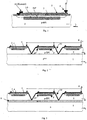
- the silicon photoelectric multiplier pursuant to the first embodiment contains p ++ conductance type substrate 1, epitaxial layer 2 (EPI), grown on substrate 1, p conductance type layer 3, n + conductance type layer 4, polysilicon resistor 5, connecting layer 4 with voltage distribution bus 6, silicon oxide layer 7, separating elements 10.
- the silicon photoelectric multiplier pursuant to the second embodiment contains, except for the above indicated elements and connections, p ++ conductance type layer 8 and n- conductance type substrate 9 (instead of p ++ conductance type substrate 1).
- the cell for the silicon photoelectric multiplier comprises p conductance type epitaxial layer 2 having 10 18 - 10 14 cms -3 of a doping agent concentration varied gradiently, p conductance type layer 3 having 10 15 - 10 17 cms -3 of the doping agent concentration, n + layer which forms the donor part of a p-n boundary, and which has 10 18 - 10 20 cms -3 of the doping agent concentration, polysilicon resistor 5 is located in each cell on silicon oxide layer 7 applied on a photosensitive surface of the epitaxial layer, said resistor 5 connects n + layer 4 with voltage distribution bus 6 .
- the doping agent concentration in the epitaxial layer is depressed in the direction from the substrate to the photosensitive surface of the photoelectric multiplier, said photosensitive surface is the epitaxial layer surface (photosensitive surface of the epitaxial layer) remoted from the substrate.
- Silicon oxide layer 7 is applied on the photosensitive surface of the silicon photoelectric multiplier, namely, on the photosensitive surface of the epitaxial layer.
- Polysilicon resistor 5, connecting n + layer 4 with voltage distribution bus 6, is located in each cell on layer 7 of silicon oxide. Separating elements 10 executing particularly function of optical barriers are disposed between the cells.
- the epitaxial layer (second embodiment of the silicon photoelectric multiplier) is grown on p ++ conductance type layer 8, located on n conductance type substrate 9 (10 15 - 10 17 cms - 3 of the doping agent concentration).
- a second (reverse) n-p boundary is made between p conductance type layers 3 and substrate 9, said boundary prevents penetration of photoelectrons, created by secondary photons of the Geiger discharge, into the sensitive region of adjacent cells. Besides the penetration of the secondary Geiger photons into the adjacent cells is prevented due to fulfillment of the separating elements (optical barriers) between the cells, which have the triangular form (V - groove) by anisotropic etching of silicon having orientation ⁇ 100>.
- the silicon photoelectric multiplier comprises the independent cells having 20-100 microns of the size. All the cells are jointed with an aluminium bus, and the identical bias voltage, exceeded the breakdown voltage, is applied to the cells, that provides working in the Geiger mode. The quenched Geiger discharge develops in the active region of the cell when a photon gets there. The quenching that is stopping the discharge, takes place due to fluctuations of the number of the charge carriers up to zero when the voltage of the p-n boundary drops, due to availability of polysilicon resistor 5 (current-limiting resistor) in each the cell. The current signals from the worked cells are summarized on a common load. The amplification of each cell constitutes up to 10 7 .
- the spread of amplification value is defined by technological spread of the cell capacity and breakdown voltage of the cell, and constitutes less than 5%. As all the cells are identical, the response of the detector to gentle light flashes is proportional to number of the worked cells, i.e. to light intensity.
- One of the features of working in the Geiger mode is the linear dependence of cell amplification from a bias voltage, that reduces requirements for stability of a power supply voltage and for a thermal stability.
- the created charge carriers are agglomerated not from the depletion region only, but also from the undepletion transitory region, in which the built-in electrical field is due to gradient of doping agent, said field forces electrons to move to the anode.
- the great depth of charge congregating is reached, that significant exceeds a depth of the depletion region, defined a low working voltage. It provides maximum high light detection efficiently at fixed cell layout and fixed working voltage.
- polysilicon resistor 5 is selected from a condition of sufficiency for extinguishing of the avalanche discharge.
- the resistor is technologically simple in manufacturing. The important feature is that the resistor is applied on a cell periphery, not occluding an active part, i.e. not reducing the light detection efficiency.
- the separating elements are disposed in the structure of the silicon photoelectric multiplier between the cells, namely separating elements having triangular form formed by anisotropic etching of silicon with orientation ⁇ 100 > in fluid etches on the base of KOH.
Abstract
Description
- The invention relates to the field of semiconductor devices, particularly to detectors with high efficiency of light emission detection, including, visible part of the spectrum, and can be used in nuclear and laser technology, and also in industrial and medical tomography etc.
- The device for single-photon detection is known ["Avalanche photodiodes and quenching circuits for single-photon detection", S.Cova, M.Ghioni, A.Lacaita, C.Samori and F.Zappa APPLIED OPTICS Vol.35 No.12 20 April 1996], the known device comprises a silicon substrate with an epitaxial layer made on it, said layer having on a surface a small (10-200 microns) region (a cell) of conductive type that is opposite to the given layer conductive type. The cell is supplied with reverse bias that exceeds breakdown voltage. When a photon is absorbed in this region the Geiger discharge takes place, said discharge is limited with an external damping resistor. Such single-photon detector has high light detection efficiency, however it has a very small sensitive region, and also it is not able to measure the light flux intensity. In order to eliminate these defects it is necessary to use a large number (= 103) of such the cells located on a common substrate having =1 MM2 of square. In this case each cell works as the above described photon detector, the device as a whole detects light intensity that is proportional to the number of the worked cells.
The device described inRU 2086047 C1 - decreasing short-wave light detection efficiency due to light absorption in the resistive layer;
- insufficiently high long-wave light detection efficiency because of a small depth of the sensitive region;
- availability of the optical connection between adjacent cells resulting in that the secondary photons appear in the Geiger discharge when one cell works, said photons can initiate actuation (lighting) of the adjacent cells. As a number of such photons is proportional to coefficient of amplification, this phenomenon limits the coefficient of amplification, efficiency, and single-electron resolution of the device. Furthermore the optical connection creates the excess noise factor , that degrades the ideal Poisson statistical characteristics and ability to account a small number of photons;
- technological complexity of resistive layer coating.
- The technical effect is to raise the efficiency of light detection in a broad band of wave lengths with the coefficient of amplification up to 107 due to increasing cell sensitiveness, to achieve high single-electron resolution, and to repress the excess noise factor.
- The single cell structure (about 20 microns of the size) which is made in a thin epitaxial layer and which provides the uniformity of the electrical field in a depletion layer having about 1 micron of depth is accepted as the nearest prior art for the cell of the silicon photoelectric multiplier. The cell structure provides a low working voltage (M.Ghioni, S.Cova, A.Lacaita, G.Ripamonti "New epitaxial avalanche diode for single-photon timing at room temperature", Electronics Letters, 24, Nº 24 (1988) 1476). The defect of the known cell is insufficient detection efficiency of the long-wave part of the spectrum (= 450 microns).
- The technical effect is to raise the light detection efficiency in a broad band of wave lengths due to increased cell sensitiveness, to achieve the high single-electron resolution.
- The publication "Photosensors" by D. Renker in "NUCLEAR INSTRUMENTS & METHODS IN PHYSICS RESEARCH; SECTION -A: ACCELERATORS, SPECTROMETERS, DETECTORS AND ASSOCIATED EQUIPMENT, ELSEVIER, AMSTERDAM, NL, vol.527, no. 1-2, 9 April 2004 (2004-04-09), pages 15-20, describes in
chapter 6. an avalanche photodiode in connection withFig. 4 and inchapter 7. an avalanche photodiode operated in Geiger mode.Fig. 4 shows the avalanche photodiode having a low resistivity silicon substrate, a drift space above the substrate, and a p-n junction above the drift space. Grooves are formed on either sides of the photodiode in order to limit surface currents. - The publication "An Advanced Study of Silicon Photomultiplier" by P. Buzhan et al. in ICFA INSTRUMENTATION BULLETIN, INTERNATIONAL COMMITTEE FOR FUTURE ACCELERATORS, STANFORD, CA, US, vol 23, 2001, pages 1-14, describes a silicon photomultiplier and its topology in Fig. 1b. The silicon photomultiplier operates in Geiger mode and an upper n+ layer of a p-n junction is connected with a polysilicon quenching resistor which is connected with a voltage distribution bus. An oxide layer is provided on the upper surface of the p-n junction and the upper n+ layer of the p-n junction is connected by a through-connection with the polysilicon quenching resistor.
- The invention is defined by the features of
claim 1. - Two embodiments of the silicon photoelectric multiplier, and the structure of the cell for the photoelectric multiplier are considered.
The technical effect is obtained (embodiment 1) due to a silicon photoelectric multiplier, comprising a p ++ conductance type substrate having 1018 - 1020 cms-3 of a doping agent concentration, consists of identical cells independent of one another, each the cell includes an p conductance type epitaxial layer grown on a substrate, said layer having 1018 - 1014 cms-3 of the doping agent concentration varied gradiently, a p conductance type layer having 1015 - 1017 cms-3 of the doping agent concentration, a n + conductance type layer having 1018 - 1020 cms-3 of the doping agent concentration, said n + conductance type layer forming a donor part of a p-n boundary, a polysilicon resistor is located on a silicon oxide layer in each the cell, said polysilicon resistor connecting the n + conductance type layer with a voltage distribution bus, and separating elements are disposed between the cells. The technical effect is obtained (enbodiment 2) due to a silicon photoelectric multiplier, comprising a n conductance type substrate, a p++ conductance type layer having 1018 - 1020 cms-3 of a doping agent concentration, said layer applied on said n conductance type substrate, consists of identical cells independent of one another, each the cell includes a p conductance type epitaxial layer having 1018 - 1014 cms -3 of the doping agent concentration varied gradiently, said p conductance type epitaxial layer grown on the p++ conductance type layer, a p conductance type layer having 1015 - 1017 cms-3 of the doping agent concentration, a n + conductance type layer having 1018 - 1020 cms-3 of the doping agent concentration, a polysilicon resistor is located on a silicon oxide layer in each the cell, said polysilicon resistor connecting the n + conductance type layer with a voltage distribution bus, and separating elements are disposed between the cells. - In the second embodiment the n conductance type substrate is used (instead of the
substrate 1, used in the first embodiment of the device), said substrate forms along with the p - layers of the cells a reverse n-p boundary. -
Fig. 1 presents a structure of the cell for the silicon photoelectric multiplier pursuant to the invention. -
Fig. 2 presents the first embodiment of the silicon photoelectric multiplier. -
Fig. 3 presents the second embodiment of the silicon photoelectric multiplier. -
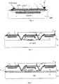
Fig. 4 presents the structure of the cell pursuant to the invention (inverse embodiment). -
Fig. 5 presents the first embodiment of the silicon photoelectric multiplier (inverse embodiment). -
Fig. 6 presents the second embodiment of the silicon photoelectric multiplier (inverse embodiment). - The silicon photoelectric multiplier pursuant to the first embodiment contains p ++
conductance type substrate 1, epitaxial layer 2 (EPI), grown onsubstrate 1, pconductance type layer 3, n +conductance type layer 4,polysilicon resistor 5, connectinglayer 4 withvoltage distribution bus 6,silicon oxide layer 7, separatingelements 10. - The silicon photoelectric multiplier pursuant to the second embodiment contains, except for the above indicated elements and connections, p ++
conductance type layer 8 and n- conductance type substrate 9 (instead of p ++ conductance type substrate 1). - The cell for the silicon photoelectric multiplier comprises p conductance type
epitaxial layer 2 having 1018 - 1014 cms -3 of a doping agent concentration varied gradiently, pconductance type layer 3 having 1015 - 1017 cms -3 of the doping agent concentration, n + layer which forms the donor part of a p-n boundary, and which has 1018 - 1020 cms-3 of the doping agent concentration,polysilicon resistor 5 is located in each cell onsilicon oxide layer 7 applied on a photosensitive surface of the epitaxial layer, saidresistor 5 connects n +layer 4 withvoltage distribution bus 6 . - The efficient light detection in a broad part of the spectrum (300 - 900 microns) along with the low working voltage and high uniformity of an electrical field is reached in such the structure by creation of the built-in electrical field, which arises due to the doping agent distribution gradiant profile specially formed in the epitaxial layer.
- The doping agent concentration in the epitaxial layer is depressed in the direction from the substrate to the photosensitive surface of the photoelectric multiplier, said photosensitive surface is the epitaxial layer surface (photosensitive surface of the epitaxial layer) remoted from the substrate.
Silicon oxide layer 7 is applied on the photosensitive surface of the silicon photoelectric multiplier, namely, on the photosensitive surface of the epitaxial layer.Polysilicon resistor 5, connecting n +layer 4 withvoltage distribution bus 6, is located in each cell onlayer 7 of silicon oxide. Separatingelements 10 executing particularly function of optical barriers are disposed between the cells. - The epitaxial layer (second embodiment of the silicon photoelectric multiplier) is grown on p ++
conductance type layer 8, located on n conductance type substrate 9 (1015 - 1017cms -3 of the doping agent concentration). A second (reverse) n-p boundary is made between pconductance type layers 3 andsubstrate 9, said boundary prevents penetration of photoelectrons, created by secondary photons of the Geiger discharge, into the sensitive region of adjacent cells. Besides the penetration of the secondary Geiger photons into the adjacent cells is prevented due to fulfillment of the separating elements (optical barriers) between the cells, which have the triangular form (V - groove) by anisotropic etching of silicon having orientation <100>. - The silicon photoelectric multiplier comprises the independent cells having 20-100 microns of the size. All the cells are jointed with an aluminium bus, and the identical bias voltage, exceeded the breakdown voltage, is applied to the cells, that provides working in the Geiger mode. The quenched Geiger discharge develops in the active region of the cell when a photon gets there. The quenching that is stopping the discharge, takes place due to fluctuations of the number of the charge carriers up to zero when the voltage of the p-n boundary drops, due to availability of polysilicon resistor 5 (current-limiting resistor) in each the cell. The current signals from the worked cells are summarized on a common load. The amplification of each cell constitutes up to 107. The spread of amplification value is defined by technological spread of the cell capacity and breakdown voltage of the cell, and constitutes less than 5%. As all the cells are identical, the response of the detector to gentle light flashes is proportional to number of the worked cells, i.e. to light intensity.
- One of the features of working in the Geiger mode is the linear dependence of cell amplification from a bias voltage, that reduces requirements for stability of a power supply voltage and for a thermal stability.
- Common bus 6 (anode) is supplied with positive voltage, its value should provide the Geiger mode (typical value lies in the range of U = + 20 - 60 v), and also provide necessary depletion depth of the layers equal to 1-2 microns. At absorption of a light quantum the created charge carriers are agglomerated not from the depletion region only, but also from the undepletion transitory region, in which the built-in electrical field is due to gradient of doping agent, said field forces electrons to move to the anode. Thus, the great depth of charge congregating is reached, that significant exceeds a depth of the depletion region, defined a low working voltage. It provides maximum high light detection efficiently at fixed cell layout and fixed working voltage.
- The value of
polysilicon resistor 5 is selected from a condition of sufficiency for extinguishing of the avalanche discharge. The resistor is technologically simple in manufacturing. The important feature is that the resistor is applied on a cell periphery, not occluding an active part, i.e. not reducing the light detection efficiency. - In order to block connections between the cells the separating elements are disposed in the structure of the silicon photoelectric multiplier between the cells, namely separating elements having triangular form formed by anisotropic etching of silicon with orientation < 100 > in fluid etches on the base of KOH.
- Allowing, that the processes in p-n and n-p boundaries run identically (with allowance for reverse signs of the electric charge carriers), at fulfillment of the claimed devices in the inverse embodiment (the layers with definite conductance type are varied to the inverse type), as shown in
figs 4-6 , their working is realized similarly, as it described for the claimed invention in the present description of the invention and in the claim. Thus the features of the inverse embodiments of the claimed devices are equivalent to the features, mentioned in the current description of the invention and in the claim.
Claims (1)
- A silicon based photo-electric multiplier, comprising:- a substrate (1) of a first conductivity type having 1018 - 1020 cm-3 of a doping agent concentration,- a plurality of cells, the cells being arranged above the substrate (1) and each one of the cells comprising:characterized in that- an epitaxial layer (2) of the first conductivity type formed on the substrate (1) and having 1014 - 1018 cm-3 of a varying doping agent concentration,- a first layer (3) of the first conductivity type formed within the epitaxial layer (2) and having 1015 - 1017 cm-3 of a doping agent concentration,- a second layer (4) of a second conductivity type formed on the first layer (3) and having 1018 - 1020 cm-3 of a doping agent concentration, the first layer (3) and the second layer (4) forming an n-p junction at an interface there between,- a silicon oxide layer (7) formed on the second layer (4), wherein- the epitaxial layer (2) comprises a spatial gradient in the doping concentration, the doping concentration being decreased from a relatively high value at the boundary between the epitaxial layer (2) and the substrate (1) to a relatively low value at the photosensitive surface of the epitaxial layer (2) in order to create a built-in electrical field of high uniformity within the epitaxial layer (2),
a polysilicon resistor (5) is located on the silicon oxide layer (7) and connects the second layer (4) to a voltage distribution bus,
and in which separating elements (10) are disposed between neighboring cells, the separating elements (10) being formed as triangular V-grooves being formed by anisotropic etching of the silicon having orientation <100> in fluid etches on the base of KOH.
Applications Claiming Priority (2)
| Application Number | Priority Date | Filing Date | Title |
|---|---|---|---|
| RU2004113616/28A RU2290721C2 (en) | 2004-05-05 | 2004-05-05 | Silicon photoelectronic multiplier (alternatives) and locations for silicon photoelectronic multiplier |
| EP05749398A EP1755171B8 (en) | 2004-05-05 | 2005-05-05 | Silicon photomultiplier with cell array |
Related Parent Applications (1)
| Application Number | Title | Priority Date | Filing Date |
|---|---|---|---|
| EP05749398A Division EP1755171B8 (en) | 2004-05-05 | 2005-05-05 | Silicon photomultiplier with cell array |
Publications (2)
| Publication Number | Publication Date |
|---|---|
| EP2144287A1 EP2144287A1 (en) | 2010-01-13 |
| EP2144287B1 true EP2144287B1 (en) | 2016-12-07 |
Family
ID=35241944
Family Applications (2)
| Application Number | Title | Priority Date | Filing Date |
|---|---|---|---|
| EP05749398A Not-in-force EP1755171B8 (en) | 2004-05-05 | 2005-05-05 | Silicon photomultiplier with cell array |
| EP09013750.6A Not-in-force EP2144287B1 (en) | 2004-05-05 | 2005-05-05 | Silicon avalanche photodetector array with graded doping concentration |
Family Applications Before (1)
| Application Number | Title | Priority Date | Filing Date |
|---|---|---|---|
| EP05749398A Not-in-force EP1755171B8 (en) | 2004-05-05 | 2005-05-05 | Silicon photomultiplier with cell array |
Country Status (9)
| Country | Link |
|---|---|
| US (1) | US7759623B2 (en) |
| EP (2) | EP1755171B8 (en) |
| JP (1) | JP2007536703A (en) |
| KR (1) | KR101113364B1 (en) |
| CN (1) | CN1998091B (en) |
| AT (1) | ATE451720T1 (en) |
| DE (1) | DE602005018200D1 (en) |
| RU (1) | RU2290721C2 (en) |
| WO (1) | WO2005106971A1 (en) |
Families Citing this family (43)
| Publication number | Priority date | Publication date | Assignee | Title |
|---|---|---|---|---|
| RU2416840C2 (en) | 2006-02-01 | 2011-04-20 | Конинклейке Филипс Электроникс, Н.В. | Avalanche photodiode in geiger counter mode |
| US20080012087A1 (en) * | 2006-04-19 | 2008-01-17 | Henri Dautet | Bonded wafer avalanche photodiode and method for manufacturing same |
| JP5183471B2 (en) | 2006-07-03 | 2013-04-17 | 浜松ホトニクス株式会社 | Photodiode array |
| US7652257B2 (en) * | 2007-06-15 | 2010-01-26 | General Electric Company | Structure of a solid state photomultiplier |
| DE102007037020B3 (en) | 2007-08-06 | 2008-08-21 | MAX-PLANCK-Gesellschaft zur Förderung der Wissenschaften e.V. | Avalanche photodiode for use in Avalanche radiation detector, has electrode arranged lateral to diode layer so that it depletes substrate laterally adjacent to layer, when resistance layer is shielded from diode layer opposite to electrode |
| CN101861527B (en) * | 2007-08-08 | 2013-08-14 | 皇家飞利浦电子股份有限公司 | Silicon photomultiplier trigger network |
| ITTO20080046A1 (en) | 2008-01-18 | 2009-07-19 | St Microelectronics Srl | PLACE OF PHOTODIODS OPERATING IN GEIGER MODES MUTUALLY INSULATED AND RELATIVE PROCESS OF MANUFACTURING |
| ITTO20080045A1 (en) | 2008-01-18 | 2009-07-19 | St Microelectronics Srl | PLACE OF PHOTODIODS OPERATING IN GEIGER MODES MUTUALLY INSULATED AND RELATIVE PROCESS OF MANUFACTURING |
| KR100987057B1 (en) * | 2008-06-12 | 2010-10-11 | 한국과학기술원 | Silicon photomultiplier with improved photodetecting efficiency and Gamma radiation detector comprising the same |
| DE102009017505B4 (en) | 2008-11-21 | 2014-07-10 | Ketek Gmbh | Radiation detector, use of a radiation detector and method of making a radiation detector |
| IT1392366B1 (en) * | 2008-12-17 | 2012-02-28 | St Microelectronics Rousset | OPERATING PHOTODIODO IN GEIGER MODE WITH INTEGRATED AND CONTROLLABLE SUPPRESSION RESISTOR, PHOTODIUM RING AND RELATIVE PROCESS OF PROCESSING |
| DE112009004341B4 (en) | 2009-01-11 | 2015-12-10 | Ketek Gmbh | Semiconductor Geiger mode microcells photodiodes |
| IT1393781B1 (en) | 2009-04-23 | 2012-05-08 | St Microelectronics Rousset | OPERATING PHOTODIODO IN GEIGER MODE WITH INTEGRATED AND CONTROLLABLE JFET EFFECT SUPPRESSION RESISTOR, PHOTODIUM RING AND ITS PROCESS OF PROCESSING |
| KR101148335B1 (en) * | 2009-07-23 | 2012-05-21 | 삼성전기주식회사 | Photoelectric multiplier using semiconductor and cell structure thereof |
| EP2462630B1 (en) | 2009-08-03 | 2016-03-30 | Max-Planck-Gesellschaft zur Förderung der Wissenschaften e.V. | Highly efficient cmos technology compatible silicon photoelectric multiplier |
| KR101084940B1 (en) * | 2009-09-28 | 2011-11-17 | 삼성전기주식회사 | Silicon photomultiplier |
| KR20110068070A (en) | 2009-12-15 | 2011-06-22 | 삼성전기주식회사 | Imaging device for low-luminance using silicon photomultiplier devices |
| WO2011122856A2 (en) * | 2010-03-30 | 2011-10-06 | 이화여자대학교 산학협력단 | Silicon photomultiplier |
| IT1399690B1 (en) | 2010-03-30 | 2013-04-26 | St Microelectronics Srl | AVALANCHE PHOTODIODO OPERATING IN GEIGER MODE WITH HIGH SIGNAL NOISE REPORT AND RELATIVE MANUFACTURING PROCEDURE |
| EP2561556B1 (en) | 2010-04-23 | 2016-06-08 | Max-Planck-Gesellschaft zur Förderung der Wissenschaften e.V. | Silicon photoelectric multiplier |
| EP2603931B1 (en) | 2010-08-10 | 2016-03-23 | Max-Planck-Gesellschaft zur Förderung der Wissenschaften e.V. | Silicon photoelectric multiplier with multiple "isochronic" read-out |
| CN102024863B (en) * | 2010-10-11 | 2013-03-27 | 湘潭大学 | High-speed enhanced ultraviolet silicon selective avalanche photodiode and manufacturing method thereof |
| KR101711087B1 (en) | 2010-12-07 | 2017-02-28 | 한국전자통신연구원 | Silicon photomultiplier and method for fabricating the same |
| KR101749240B1 (en) | 2010-12-17 | 2017-06-21 | 한국전자통신연구원 | Optical Structure on Semiconductor Photomultiplier and Fabrication Method Thereof |
| KR101648023B1 (en) * | 2010-12-21 | 2016-08-12 | 한국전자통신연구원 | Silicon photomultiplier with trench isolation |
| CA2821578C (en) * | 2010-12-21 | 2016-03-22 | Max-Planck-Gesellschaft Zur Forderung Der Wissenschaften E.V. | Silicon photoelectric multiplier with optical cross-talk suppression due to special properties of the substrate |
| US8368159B2 (en) | 2011-07-08 | 2013-02-05 | Excelitas Canada, Inc. | Photon counting UV-APD |
| KR101283534B1 (en) * | 2011-07-28 | 2013-07-15 | 이화여자대학교 산학협력단 | Method for manufacturing silicon photomultiplier device |
| US8871557B2 (en) | 2011-09-02 | 2014-10-28 | Electronics And Telecommunications Research Institute | Photomultiplier and manufacturing method thereof |
| JP5791461B2 (en) * | 2011-10-21 | 2015-10-07 | 浜松ホトニクス株式会社 | Photodetector |
| JP5984617B2 (en) * | 2012-10-18 | 2016-09-06 | 浜松ホトニクス株式会社 | Photodiode array |
| JP5963642B2 (en) | 2012-10-29 | 2016-08-03 | 浜松ホトニクス株式会社 | Photodiode array |
| US20140159180A1 (en) * | 2012-12-06 | 2014-06-12 | Agency For Science, Technology And Research | Semiconductor resistor structure and semiconductor photomultiplier device |
| KR101395102B1 (en) | 2013-02-14 | 2014-05-16 | 한국과학기술원 | A packaging method of silicon photomultiplier using pcb plate |
| JP5925711B2 (en) | 2013-02-20 | 2016-05-25 | 浜松ホトニクス株式会社 | Detector, PET apparatus and X-ray CT apparatus |
| EP2793273B1 (en) * | 2013-04-17 | 2016-12-28 | Max-Planck-Gesellschaft zur Förderung der Wissenschaften e.V. | Silicon photomultiplier with very low optical cross-talk and improved readout |
| US9410901B2 (en) * | 2014-03-17 | 2016-08-09 | Kla-Tencor Corporation | Image sensor, an inspection system and a method of inspecting an article |
| TW202243228A (en) * | 2014-06-27 | 2022-11-01 | 日商半導體能源研究所股份有限公司 | Imaging device and electronic device |
| DE102018119710A1 (en) * | 2018-08-14 | 2020-02-20 | Universität Leipzig | DEVICE AND METHOD FOR DETERMINING A WAVELENGTH OF A RADIATION |
| CN109276268A (en) * | 2018-11-21 | 2019-01-29 | 京东方科技集团股份有限公司 | X-ray detection device and its manufacturing method |
| US11428826B2 (en) | 2019-09-09 | 2022-08-30 | Semiconductor Components Industries, Llc | Silicon photomultipliers with split microcells |
| RU2770147C1 (en) * | 2021-06-21 | 2022-04-14 | Садыгов Зираддин Ягуб оглы | Micropixel avalanche photodiode |
| CN114093962B (en) * | 2021-11-22 | 2024-04-09 | 季华实验室 | Single photon avalanche diode and photoelectric detector array |
Family Cites Families (36)
| Publication number | Priority date | Publication date | Assignee | Title |
|---|---|---|---|---|
| FR2108781B1 (en) * | 1970-10-05 | 1974-10-31 | Radiotechnique Compelec | |
| JPS5252593A (en) * | 1975-10-27 | 1977-04-27 | Nippon Telegr & Teleph Corp <Ntt> | Semiconductor light receiving diode |
| CA1177148A (en) * | 1981-10-06 | 1984-10-30 | Robert J. Mcintyre | Avalanche photodiode array |
| JPS59119772A (en) * | 1982-12-24 | 1984-07-11 | Fujitsu Ltd | Semiconductor photo detector |
| NL187416C (en) | 1983-07-14 | 1991-09-16 | Philips Nv | RADIATION-SENSITIVE SEMICONDUCTOR DEVICE. |
| US4586068A (en) | 1983-10-07 | 1986-04-29 | Rockwell International Corporation | Solid state photomultiplier |
| JPH0799868B2 (en) | 1984-12-26 | 1995-10-25 | 日本放送協会 | Solid-state imaging device |
| JPS61154063A (en) * | 1984-12-26 | 1986-07-12 | Toshiba Corp | Optical semiconductor device and manufacture thereof |
| JPS63124458A (en) | 1986-11-12 | 1988-05-27 | Mitsubishi Electric Corp | Photodetector |
| US5146296A (en) | 1987-12-03 | 1992-09-08 | Xsirius Photonics, Inc. | Devices for detecting and/or imaging single photoelectron |
| US5923071A (en) | 1992-06-12 | 1999-07-13 | Seiko Instruments Inc. | Semiconductor device having a semiconductor film of low oxygen concentration |
| JPH07240534A (en) * | 1993-03-16 | 1995-09-12 | Seiko Instr Inc | Photoelectric conversion semiconductor device and its manufacture |
| RU2105388C1 (en) | 1996-04-10 | 1998-02-20 | Виктор Михайлович Горловин | Avalanche photodetector |
| RU2086047C1 (en) | 1996-05-30 | 1997-07-27 | Зираддин Ягуб-оглы Садыгов | Cumulative photodetector |
| US5844291A (en) | 1996-12-20 | 1998-12-01 | Board Of Regents, The University Of Texas System | Wide wavelength range high efficiency avalanche light detector with negative feedback |
| JPH1126741A (en) * | 1997-07-04 | 1999-01-29 | Toshiba Corp | Solid-state image pick-up device |
| US5880490A (en) | 1997-07-28 | 1999-03-09 | Board Of Regents, The University Of Texas System | Semiconductor radiation detectors with intrinsic avalanche multiplication in self-limiting mode of operation |
| IT246635Y1 (en) | 1999-04-09 | 2002-04-09 | Claber Spa | CONTROL SOLENOID FOR SOLENOID VALVE IN PARTICULAR FOR THE CONTROL OF IRRIGATION SYSTEMS |
| IT1317199B1 (en) | 2000-04-10 | 2003-05-27 | Milano Politecnico | ULTRASENSITIVE PHOTO-DETECTOR DEVICE WITH INTEGRATED MICROMETRIC DIAPHRAGM FOR CONFOCAL MICROSCOPES |
| US6541836B2 (en) | 2001-02-21 | 2003-04-01 | Photon Imaging, Inc. | Semiconductor radiation detector with internal gain |
| IES20010616A2 (en) | 2001-06-28 | 2002-05-15 | Nat Microelectronics Res Ct | Microelectronic device and method of its manufacture |
| WO2004027879A2 (en) | 2002-09-19 | 2004-04-01 | Quantum Semiconductor Llc | Light-sensing device |
| US6838741B2 (en) * | 2002-12-10 | 2005-01-04 | General Electtric Company | Avalanche photodiode for use in harsh environments |
| WO2004100200A2 (en) | 2003-05-01 | 2004-11-18 | Yale University | Solid state microchannel plate photodetector |
| WO2005048319A2 (en) | 2003-11-06 | 2005-05-26 | Yale University | Large-area detector |
| US7160753B2 (en) | 2004-03-16 | 2007-01-09 | Voxtel, Inc. | Silicon-on-insulator active pixel sensors |
| JP4841834B2 (en) | 2004-12-24 | 2011-12-21 | 浜松ホトニクス株式会社 | Photodiode array |
| ATE514105T1 (en) | 2005-04-22 | 2011-07-15 | Koninkl Philips Electronics Nv | DIGITAL SILICON PHOTO MULTIPLIER FOR A TOF PET |
| GB2426576A (en) | 2005-05-27 | 2006-11-29 | Sensl Technologies Ltd | Light sensor module comprising a plurality of elements in a close-tiled arrangement |
| GB2426575A (en) | 2005-05-27 | 2006-11-29 | Sensl Technologies Ltd | Photon detector using controlled sequences of reset and discharge of a capacitor to sense photons |
| US7268339B1 (en) | 2005-09-27 | 2007-09-11 | Radiation Monitoring Devices, Inc. | Large area semiconductor detector with internal gain |
| RU2416840C2 (en) | 2006-02-01 | 2011-04-20 | Конинклейке Филипс Электроникс, Н.В. | Avalanche photodiode in geiger counter mode |
| JP5183471B2 (en) | 2006-07-03 | 2013-04-17 | 浜松ホトニクス株式会社 | Photodiode array |
| WO2008011617A2 (en) | 2006-07-21 | 2008-01-24 | The Regents Of The University Of California | Shallow-trench-isolation (sti)-bounded single-photon avalanche photodetectors |
| GB2446185A (en) | 2006-10-30 | 2008-08-06 | Sensl Technologies Ltd | Optical assembly and method of assembly |
| GB2447264A (en) | 2007-03-05 | 2008-09-10 | Sensl Technologies Ltd | Optical position sensitive detector |
-
2004
- 2004-05-05 RU RU2004113616/28A patent/RU2290721C2/en not_active IP Right Cessation
-
2005
- 2005-05-05 DE DE602005018200T patent/DE602005018200D1/en active Active
- 2005-05-05 CN CN2005800192481A patent/CN1998091B/en not_active Expired - Fee Related
- 2005-05-05 US US11/568,646 patent/US7759623B2/en not_active Expired - Fee Related
- 2005-05-05 EP EP05749398A patent/EP1755171B8/en not_active Not-in-force
- 2005-05-05 WO PCT/RU2005/000242 patent/WO2005106971A1/en active Application Filing
- 2005-05-05 EP EP09013750.6A patent/EP2144287B1/en not_active Not-in-force
- 2005-05-05 JP JP2007511306A patent/JP2007536703A/en active Pending
- 2005-05-05 KR KR1020067025572A patent/KR101113364B1/en active IP Right Grant
- 2005-05-05 AT AT05749398T patent/ATE451720T1/en not_active IP Right Cessation
Non-Patent Citations (1)
| Title |
|---|
| None * |
Also Published As
| Publication number | Publication date |
|---|---|
| EP1755171B8 (en) | 2010-05-19 |
| KR101113364B1 (en) | 2012-03-02 |
| RU2290721C2 (en) | 2006-12-27 |
| EP1755171B1 (en) | 2009-12-09 |
| KR20070051782A (en) | 2007-05-18 |
| EP1755171A4 (en) | 2008-02-27 |
| US20080251692A1 (en) | 2008-10-16 |
| US7759623B2 (en) | 2010-07-20 |
| CN1998091B (en) | 2010-09-29 |
| EP2144287A1 (en) | 2010-01-13 |
| EP1755171A1 (en) | 2007-02-21 |
| ATE451720T1 (en) | 2009-12-15 |
| JP2007536703A (en) | 2007-12-13 |
| DE602005018200D1 (en) | 2010-01-21 |
| WO2005106971A1 (en) | 2005-11-10 |
| CN1998091A (en) | 2007-07-11 |
Similar Documents
| Publication | Publication Date | Title |
|---|---|---|
| EP2144287B1 (en) | Silicon avalanche photodetector array with graded doping concentration | |
| US11239382B2 (en) | Semiconductor photomultiplier | |
| US9437630B2 (en) | Semiconductor photomultiplier | |
| US8729654B2 (en) | Back-side readout semiconductor photomultiplier | |
| EP3646064B1 (en) | Semiconductor photomultiplier with improved operating voltage range | |
| US20130200477A1 (en) | Semiconductor photomultiplier device | |
| US20140159180A1 (en) | Semiconductor resistor structure and semiconductor photomultiplier device | |
| US10290760B2 (en) | Process of manufacturing an avalanche diode | |
| US8766339B2 (en) | Highly efficient CMOS technology compatible silicon photoelectric multiplier | |
| Hossain et al. | Low breakdown voltage CMOS compatible pn junction avalanche photodiode | |
| CN211957666U (en) | Photoelectric avalanche diode applied to sensing front end of high-sensitivity optical coupling isolation chip | |
| Choong et al. | Back-side readout silicon photomultiplier | |
| Jiang et al. | A novel photodiode array structure with double-layer SiO2 isolation | |
| Janeković et al. | Optimization of floating guard ring parameters in separate-absorption-and-multiplication silicon avalanche photodiode structure | |
| Sun et al. | Novel silicon photomultiplier with vertical bulk-Si quenching resistors | |
| Sun et al. | Punch through float-zone silicon phototransistors with high linearity and sensitivity | |
| Pagano et al. | Silicon Photomultipliers: Dark Current and its Statistical Spread | |
| Zimmermann et al. | Ultralow-capacitance lateral pin photodiode in a thin c-Si film | |
| Anuar et al. | Modelling SOI PIN Diode for Energy Harvesting Application | |
| Baldawi et al. | Modelling of High Quantum Efficiency Avalanche Photodiode | |
| Valvo et al. | Statistical analysis of dark current in silicon photomultipliers | |
| Vitzethum et al. | A novel photoconductive detector for single photon detection | |
| Tavernier et al. | From light to electric current—The photodiode |
Legal Events
| Date | Code | Title | Description |
|---|---|---|---|
| PUAI | Public reference made under article 153(3) epc to a published international application that has entered the european phase |
Free format text: ORIGINAL CODE: 0009012 |
|
| AC | Divisional application: reference to earlier application |
Ref document number: 1755171 Country of ref document: EP Kind code of ref document: P |
|
| AK | Designated contracting states |
Kind code of ref document: A1 Designated state(s): AT BE BG CH CY CZ DE DK EE ES FI FR GB GR HU IE IS IT LI LT LU MC NL PL PT RO SE SI SK TR |
|
| RIN1 | Information on inventor provided before grant (corrected) |
Inventor name: FILATOV, LEONID ANATOLIEVICH Inventor name: MIRZOYAN, RAZMIK Inventor name: KLEMIN, SERGEY NIKOLAEVICH Inventor name: DOLGOSHEIN, BORIS ANATOLIEVICH Inventor name: POPOVA, ELENA VIKTOROVNA Inventor name: TESHIMA, MASAHIRO PROF. DR. |
|
| RIN1 | Information on inventor provided before grant (corrected) |
Inventor name: TESHIMA, MASAHIRO PROF. DR. Inventor name: MIRZOYAN, RAZMIK Inventor name: KLEMIN, SERGEY NIKOLAEVICH Inventor name: FILATOV, LEONID ANATOLIEVICH Inventor name: DOLGOSHEIN, BORIS ANATOLIEVICH Inventor name: POPOVA, ELENA VIKTOROVNA |
|
| 17P | Request for examination filed |
Effective date: 20100611 |
|
| 17Q | First examination report despatched |
Effective date: 20100729 |
|
| REG | Reference to a national code |
Ref country code: DE Ref legal event code: R079 Ref document number: 602005050882 Country of ref document: DE Free format text: PREVIOUS MAIN CLASS: H01L0027115000 Ipc: H01L0027144000 |
|
| GRAP | Despatch of communication of intention to grant a patent |
Free format text: ORIGINAL CODE: EPIDOSNIGR1 |
|
| RIC1 | Information provided on ipc code assigned before grant |
Ipc: H01L 31/107 20060101ALI20160622BHEP Ipc: H01L 31/115 20060101ALI20160622BHEP Ipc: H01L 27/144 20060101AFI20160622BHEP Ipc: H01L 27/146 20060101ALI20160622BHEP |
|
| INTG | Intention to grant announced |
Effective date: 20160708 |
|
| GRAS | Grant fee paid |
Free format text: ORIGINAL CODE: EPIDOSNIGR3 |
|
| GRAA | (expected) grant |
Free format text: ORIGINAL CODE: 0009210 |
|
| AC | Divisional application: reference to earlier application |
Ref document number: 1755171 Country of ref document: EP Kind code of ref document: P |
|
| AK | Designated contracting states |
Kind code of ref document: B1 Designated state(s): AT BE BG CH CY CZ DE DK EE ES FI FR GB GR HU IE IS IT LI LT LU MC NL PL PT RO SE SI SK TR |
|
| REG | Reference to a national code |
Ref country code: GB Ref legal event code: FG4D |
|
| REG | Reference to a national code |
Ref country code: CH Ref legal event code: EP Ref country code: AT Ref legal event code: REF Ref document number: 852399 Country of ref document: AT Kind code of ref document: T Effective date: 20161215 |
|
| REG | Reference to a national code |
Ref country code: IE Ref legal event code: FG4D |
|
| REG | Reference to a national code |
Ref country code: DE Ref legal event code: R096 Ref document number: 602005050882 Country of ref document: DE |
|
| REG | Reference to a national code |
Ref country code: LT Ref legal event code: MG4D |
|
| REG | Reference to a national code |
Ref country code: NL Ref legal event code: MP Effective date: 20161207 |
|
| PG25 | Lapsed in a contracting state [announced via postgrant information from national office to epo] |
Ref country code: GR Free format text: LAPSE BECAUSE OF FAILURE TO SUBMIT A TRANSLATION OF THE DESCRIPTION OR TO PAY THE FEE WITHIN THE PRESCRIBED TIME-LIMIT Effective date: 20170308 Ref country code: LT Free format text: LAPSE BECAUSE OF FAILURE TO SUBMIT A TRANSLATION OF THE DESCRIPTION OR TO PAY THE FEE WITHIN THE PRESCRIBED TIME-LIMIT Effective date: 20161207 Ref country code: SE Free format text: LAPSE BECAUSE OF FAILURE TO SUBMIT A TRANSLATION OF THE DESCRIPTION OR TO PAY THE FEE WITHIN THE PRESCRIBED TIME-LIMIT Effective date: 20161207 |
|
| REG | Reference to a national code |
Ref country code: AT Ref legal event code: MK05 Ref document number: 852399 Country of ref document: AT Kind code of ref document: T Effective date: 20161207 |
|
| REG | Reference to a national code |
Ref country code: FR Ref legal event code: PLFP Year of fee payment: 13 |
|
| PG25 | Lapsed in a contracting state [announced via postgrant information from national office to epo] |
Ref country code: ES Free format text: LAPSE BECAUSE OF FAILURE TO SUBMIT A TRANSLATION OF THE DESCRIPTION OR TO PAY THE FEE WITHIN THE PRESCRIBED TIME-LIMIT Effective date: 20161207 Ref country code: FI Free format text: LAPSE BECAUSE OF FAILURE TO SUBMIT A TRANSLATION OF THE DESCRIPTION OR TO PAY THE FEE WITHIN THE PRESCRIBED TIME-LIMIT Effective date: 20161207 |
|
| PG25 | Lapsed in a contracting state [announced via postgrant information from national office to epo] |
Ref country code: NL Free format text: LAPSE BECAUSE OF FAILURE TO SUBMIT A TRANSLATION OF THE DESCRIPTION OR TO PAY THE FEE WITHIN THE PRESCRIBED TIME-LIMIT Effective date: 20161207 |
|
| PG25 | Lapsed in a contracting state [announced via postgrant information from national office to epo] |
Ref country code: CZ Free format text: LAPSE BECAUSE OF FAILURE TO SUBMIT A TRANSLATION OF THE DESCRIPTION OR TO PAY THE FEE WITHIN THE PRESCRIBED TIME-LIMIT Effective date: 20161207 Ref country code: SK Free format text: LAPSE BECAUSE OF FAILURE TO SUBMIT A TRANSLATION OF THE DESCRIPTION OR TO PAY THE FEE WITHIN THE PRESCRIBED TIME-LIMIT Effective date: 20161207 Ref country code: IS Free format text: LAPSE BECAUSE OF FAILURE TO SUBMIT A TRANSLATION OF THE DESCRIPTION OR TO PAY THE FEE WITHIN THE PRESCRIBED TIME-LIMIT Effective date: 20170407 Ref country code: RO Free format text: LAPSE BECAUSE OF FAILURE TO SUBMIT A TRANSLATION OF THE DESCRIPTION OR TO PAY THE FEE WITHIN THE PRESCRIBED TIME-LIMIT Effective date: 20161207 Ref country code: EE Free format text: LAPSE BECAUSE OF FAILURE TO SUBMIT A TRANSLATION OF THE DESCRIPTION OR TO PAY THE FEE WITHIN THE PRESCRIBED TIME-LIMIT Effective date: 20161207 |
|
| PG25 | Lapsed in a contracting state [announced via postgrant information from national office to epo] |
Ref country code: BG Free format text: LAPSE BECAUSE OF FAILURE TO SUBMIT A TRANSLATION OF THE DESCRIPTION OR TO PAY THE FEE WITHIN THE PRESCRIBED TIME-LIMIT Effective date: 20170307 Ref country code: BE Free format text: LAPSE BECAUSE OF FAILURE TO SUBMIT A TRANSLATION OF THE DESCRIPTION OR TO PAY THE FEE WITHIN THE PRESCRIBED TIME-LIMIT Effective date: 20161207 Ref country code: PT Free format text: LAPSE BECAUSE OF FAILURE TO SUBMIT A TRANSLATION OF THE DESCRIPTION OR TO PAY THE FEE WITHIN THE PRESCRIBED TIME-LIMIT Effective date: 20170407 Ref country code: IT Free format text: LAPSE BECAUSE OF FAILURE TO SUBMIT A TRANSLATION OF THE DESCRIPTION OR TO PAY THE FEE WITHIN THE PRESCRIBED TIME-LIMIT Effective date: 20161207 Ref country code: AT Free format text: LAPSE BECAUSE OF FAILURE TO SUBMIT A TRANSLATION OF THE DESCRIPTION OR TO PAY THE FEE WITHIN THE PRESCRIBED TIME-LIMIT Effective date: 20161207 Ref country code: LU Free format text: LAPSE BECAUSE OF NON-PAYMENT OF DUE FEES Effective date: 20170531 Ref country code: PL Free format text: LAPSE BECAUSE OF FAILURE TO SUBMIT A TRANSLATION OF THE DESCRIPTION OR TO PAY THE FEE WITHIN THE PRESCRIBED TIME-LIMIT Effective date: 20161207 |
|
| REG | Reference to a national code |
Ref country code: DE Ref legal event code: R097 Ref document number: 602005050882 Country of ref document: DE |
|
| PLBE | No opposition filed within time limit |
Free format text: ORIGINAL CODE: 0009261 |
|
| STAA | Information on the status of an ep patent application or granted ep patent |
Free format text: STATUS: NO OPPOSITION FILED WITHIN TIME LIMIT |
|
| 26N | No opposition filed |
Effective date: 20170908 |
|
| PG25 | Lapsed in a contracting state [announced via postgrant information from national office to epo] |
Ref country code: SI Free format text: LAPSE BECAUSE OF FAILURE TO SUBMIT A TRANSLATION OF THE DESCRIPTION OR TO PAY THE FEE WITHIN THE PRESCRIBED TIME-LIMIT Effective date: 20161207 Ref country code: DK Free format text: LAPSE BECAUSE OF FAILURE TO SUBMIT A TRANSLATION OF THE DESCRIPTION OR TO PAY THE FEE WITHIN THE PRESCRIBED TIME-LIMIT Effective date: 20161207 |
|
| REG | Reference to a national code |
Ref country code: CH Ref legal event code: PL |
|
| PG25 | Lapsed in a contracting state [announced via postgrant information from national office to epo] |
Ref country code: MC Free format text: LAPSE BECAUSE OF FAILURE TO SUBMIT A TRANSLATION OF THE DESCRIPTION OR TO PAY THE FEE WITHIN THE PRESCRIBED TIME-LIMIT Effective date: 20161207 |
|
| REG | Reference to a national code |
Ref country code: IE Ref legal event code: MM4A |
|
| PG25 | Lapsed in a contracting state [announced via postgrant information from national office to epo] |
Ref country code: LI Free format text: LAPSE BECAUSE OF NON-PAYMENT OF DUE FEES Effective date: 20170531 Ref country code: CH Free format text: LAPSE BECAUSE OF NON-PAYMENT OF DUE FEES Effective date: 20170531 |
|
| PG25 | Lapsed in a contracting state [announced via postgrant information from national office to epo] |
Ref country code: LU Free format text: LAPSE BECAUSE OF NON-PAYMENT OF DUE FEES Effective date: 20170505 |
|
| PG25 | Lapsed in a contracting state [announced via postgrant information from national office to epo] |
Ref country code: IE Free format text: LAPSE BECAUSE OF NON-PAYMENT OF DUE FEES Effective date: 20170505 |
|
| REG | Reference to a national code |
Ref country code: FR Ref legal event code: PLFP Year of fee payment: 14 |
|
| PGFP | Annual fee paid to national office [announced via postgrant information from national office to epo] |
Ref country code: FR Payment date: 20180529 Year of fee payment: 14 |
|
| PGFP | Annual fee paid to national office [announced via postgrant information from national office to epo] |
Ref country code: GB Payment date: 20180626 Year of fee payment: 14 |
|
| PG25 | Lapsed in a contracting state [announced via postgrant information from national office to epo] |
Ref country code: HU Free format text: LAPSE BECAUSE OF FAILURE TO SUBMIT A TRANSLATION OF THE DESCRIPTION OR TO PAY THE FEE WITHIN THE PRESCRIBED TIME-LIMIT; INVALID AB INITIO Effective date: 20050505 |
|
| PG25 | Lapsed in a contracting state [announced via postgrant information from national office to epo] |
Ref country code: CY Free format text: LAPSE BECAUSE OF NON-PAYMENT OF DUE FEES Effective date: 20161207 |
|
| GBPC | Gb: european patent ceased through non-payment of renewal fee |
Effective date: 20190505 |
|
| PG25 | Lapsed in a contracting state [announced via postgrant information from national office to epo] |
Ref country code: TR Free format text: LAPSE BECAUSE OF FAILURE TO SUBMIT A TRANSLATION OF THE DESCRIPTION OR TO PAY THE FEE WITHIN THE PRESCRIBED TIME-LIMIT Effective date: 20161207 |
|
| PG25 | Lapsed in a contracting state [announced via postgrant information from national office to epo] |
Ref country code: GB Free format text: LAPSE BECAUSE OF NON-PAYMENT OF DUE FEES Effective date: 20190505 |
|
| PG25 | Lapsed in a contracting state [announced via postgrant information from national office to epo] |
Ref country code: FR Free format text: LAPSE BECAUSE OF NON-PAYMENT OF DUE FEES Effective date: 20190531 |
|
| PGFP | Annual fee paid to national office [announced via postgrant information from national office to epo] |
Ref country code: DE Payment date: 20200325 Year of fee payment: 16 |
|
| REG | Reference to a national code |
Ref country code: DE Ref legal event code: R119 Ref document number: 602005050882 Country of ref document: DE |
|
| PG25 | Lapsed in a contracting state [announced via postgrant information from national office to epo] |
Ref country code: DE Free format text: LAPSE BECAUSE OF NON-PAYMENT OF DUE FEES Effective date: 20211201 |