EP2144002B1 - Flow sleeve with tabbed direct combustion liner cooling air - Google Patents
Flow sleeve with tabbed direct combustion liner cooling air Download PDFInfo
- Publication number
- EP2144002B1 EP2144002B1 EP09250781.3A EP09250781A EP2144002B1 EP 2144002 B1 EP2144002 B1 EP 2144002B1 EP 09250781 A EP09250781 A EP 09250781A EP 2144002 B1 EP2144002 B1 EP 2144002B1
- Authority
- EP
- European Patent Office
- Prior art keywords
- flow sleeve
- combustion
- holes
- tabs
- combustion liner
- Prior art date
- Legal status (The legal status is an assumption and is not a legal conclusion. Google has not performed a legal analysis and makes no representation as to the accuracy of the status listed.)
- Ceased
Links
- 238000002485 combustion reaction Methods 0.000 title claims description 34
- 238000001816 cooling Methods 0.000 title claims description 10
- 238000011144 upstream manufacturing Methods 0.000 description 4
- 239000000446 fuel Substances 0.000 description 1
- 238000004519 manufacturing process Methods 0.000 description 1
- 238000012986 modification Methods 0.000 description 1
- 230000004048 modification Effects 0.000 description 1
Images
Classifications
-
- F—MECHANICAL ENGINEERING; LIGHTING; HEATING; WEAPONS; BLASTING
- F23—COMBUSTION APPARATUS; COMBUSTION PROCESSES
- F23R—GENERATING COMBUSTION PRODUCTS OF HIGH PRESSURE OR HIGH VELOCITY, e.g. GAS-TURBINE COMBUSTION CHAMBERS
- F23R3/00—Continuous combustion chambers using liquid or gaseous fuel
- F23R3/42—Continuous combustion chambers using liquid or gaseous fuel characterised by the arrangement or form of the flame tubes or combustion chambers
- F23R3/46—Combustion chambers comprising an annular arrangement of several essentially tubular flame tubes within a common annular casing or within individual casings
- F23R3/48—Flame tube interconnectors, e.g. cross-over tubes
-
- F—MECHANICAL ENGINEERING; LIGHTING; HEATING; WEAPONS; BLASTING
- F23—COMBUSTION APPARATUS; COMBUSTION PROCESSES
- F23R—GENERATING COMBUSTION PRODUCTS OF HIGH PRESSURE OR HIGH VELOCITY, e.g. GAS-TURBINE COMBUSTION CHAMBERS
- F23R3/00—Continuous combustion chambers using liquid or gaseous fuel
- F23R3/002—Wall structures
-
- F—MECHANICAL ENGINEERING; LIGHTING; HEATING; WEAPONS; BLASTING
- F23—COMBUSTION APPARATUS; COMBUSTION PROCESSES
- F23R—GENERATING COMBUSTION PRODUCTS OF HIGH PRESSURE OR HIGH VELOCITY, e.g. GAS-TURBINE COMBUSTION CHAMBERS
- F23R3/00—Continuous combustion chambers using liquid or gaseous fuel
- F23R3/02—Continuous combustion chambers using liquid or gaseous fuel characterised by the air-flow or gas-flow configuration
- F23R3/04—Air inlet arrangements
- F23R3/06—Arrangement of apertures along the flame tube
-
- F—MECHANICAL ENGINEERING; LIGHTING; HEATING; WEAPONS; BLASTING
- F23—COMBUSTION APPARATUS; COMBUSTION PROCESSES
- F23R—GENERATING COMBUSTION PRODUCTS OF HIGH PRESSURE OR HIGH VELOCITY, e.g. GAS-TURBINE COMBUSTION CHAMBERS
- F23R2900/00—Special features of, or arrangements for continuous combustion chambers; Combustion processes therefor
- F23R2900/03044—Impingement cooled combustion chamber walls or subassemblies
Definitions
- the present invention relates to a flow sleeve for controlling cooling airflow to an outer periphery of a combustion liner in a gas turbine engine.
- Gas turbine engines typically include a compressor section that compresses air and delivers it downstream into a combustion section. The air is mixed with fuel in the combustion section and burned. Products of this combustion pass downstream towards a turbine section, to drive turbine rotors.
- a combustion sleeve directs the products of combustion from the combustion section downstream toward the turbine rotors.
- the combustion liner becomes quite hot from the products of combustion.
- a part called a flow sleeve is mounted between an outer housing and the combustion liner, and provided with a plurality of openings. Cooling air is provided radially outwardly of the flow sleeve, and is directed through the holes at the outer periphery of the combustion liner. In this way, the combustion liner is cooled.
- a plurality of tubular members extend about the holes, and from an inner periphery, to form conduits for controlling the direction in which the air is moved against the combustion liner.
- the tubular members add expense, and are complex to manufacture.
- a combustion duct having the features of the preamble of claim 1 is disclosed in US 6,484,505 B1 .
- the present invention provides a combustion duct as set forth in claim 1.
- the tabs control the air flow direction but are less expensive than the prior art.
- a combustion duct 20 for use in a gas turbine engine is illustrated in Figure 1 .
- An outer housing 22 connects to a downstream duct 24 leading to a turbine section (not shown).
- Outer housing 22 also surrounds a combustion liner 31.
- Combustion liner 31 receives products of combustion X from combustion section 18 and delivers them downstream into duct 24.
- a flow sleeve 32 is positioned radially between the outer housing 22 and the combustion liner 31.
- a chamber 30 between the flow sleeve 32 and the outer housing 22 receives cooling air, such as from an upstream compressor (not shown). Holes 34 are formed through the flow sleeve 32. Air passes from the chamber 30 through the holes 34, and against the outer periphery of the combustion liner 31.
- tab ring 36 has a cylindrical base 38, and a plurality of tabs 40. Further, the base 38 includes holes 37 to be aligned with the last row of holes 35. As can be appreciated from Figure 2 , the tabs 40 do not extend over more than 180° defined about an axis extending through the holes 35. That is, tabs 40 are only on the downstream side of the holes 35. More specifically, as can be appreciated, the tabs 40 extend across less than 90°, and are generally formed to be tangent to an outer periphery of the hole at an upstream side.
- the tab 36 ring as disclosed extends over an entire 360° range about a central axis Z of the flow sleeve 32.
- the tab ring 36 may extend for less than 360°, but in accordance with the invention, extends for at least 270° about the axis.
- the tab ring 36 does extend for 360° and is a complete ring.
- the tabs 40 and base 38 are formed as a single piece in a disclosed embodiment.
- tabs 40 extend radially inwardly from the base 38.
- Figure 4 shows the tab 40 extending inwardly from base 38, and positioned inwardly of the flow sleeve 32.
- the tabs 40 being aligned with the outer row of holes 35 shields cooling air from downstream cross-flow. Instead, cooling air from the holes 35 flows to an outer periphery of the combustion liner 31. Further, since the tabs 40 are only on a downstream side of the holes 35, and the base 38 does not extend as far radially inwardly as does the tab 40, the air is urged to flow back upstream, through the space 39 provided by the base 38. There will be a greater resistance to downstream flow due to the tab 40.
- the tab ring 36 can be said to have an upstream side and a downstream side, and tabs 40 are at the downstream side.
- this description allows for a portion of the base to extend on a downstream side of the tabs 40. That is, the tabs 40 need not be at an extreme edge of the ring 36, and can still be said to be at the downstream side.
Landscapes
- Engineering & Computer Science (AREA)
- Chemical & Material Sciences (AREA)
- Combustion & Propulsion (AREA)
- Mechanical Engineering (AREA)
- General Engineering & Computer Science (AREA)
- Turbine Rotor Nozzle Sealing (AREA)
Description
- The present invention relates to a flow sleeve for controlling cooling airflow to an outer periphery of a combustion liner in a gas turbine engine.
- Gas turbine engines are known, and typically include a compressor section that compresses air and delivers it downstream into a combustion section. The air is mixed with fuel in the combustion section and burned. Products of this combustion pass downstream towards a turbine section, to drive turbine rotors.
- A combustion sleeve directs the products of combustion from the combustion section downstream toward the turbine rotors. The combustion liner becomes quite hot from the products of combustion. Thus, it is known to provide cooling air to an outer periphery of the combustion liner.
- A part called a flow sleeve is mounted between an outer housing and the combustion liner, and provided with a plurality of openings. Cooling air is provided radially outwardly of the flow sleeve, and is directed through the holes at the outer periphery of the combustion liner. In this way, the combustion liner is cooled.
- In one known flow sleeve, such as that found in
US 6,484,505 B1 , a plurality of tubular members extend about the holes, and from an inner periphery, to form conduits for controlling the direction in which the air is moved against the combustion liner. The tubular members add expense, and are complex to manufacture. - A combustion duct having the features of the preamble of claim 1 is disclosed in
US 6,484,505 B1 . - The present invention provides a combustion duct as set forth in claim 1.
- The tabs control the air flow direction but are less expensive than the prior art.
- These and other features of the present invention can be best understood from the following specification and drawings, the following of which is a brief description.
-
-
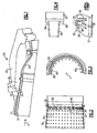
Figure 1 shows a cross-sectional view of a combustion duct. -
Figure 2 shows a cross-sectional view of a flow sleeve with a tab ring. -
Figure 3 is an end view of theFigure 2 tab ring. -
Figure 4 shows a plan view tab of theFigure 2 tab ring. -
Figure 5 shows a cross-sectional partial view of the flow sleeve and cooling tabs. - A
combustion duct 20 for use in a gas turbine engine is illustrated inFigure 1 . Anouter housing 22 connects to adownstream duct 24 leading to a turbine section (not shown).Outer housing 22 also surrounds acombustion liner 31.Combustion liner 31 receives products of combustion X from combustion section 18 and delivers them downstream intoduct 24. Aflow sleeve 32 is positioned radially between theouter housing 22 and thecombustion liner 31. Achamber 30 between theflow sleeve 32 and theouter housing 22 receives cooling air, such as from an upstream compressor (not shown).Holes 34 are formed through theflow sleeve 32. Air passes from thechamber 30 through theholes 34, and against the outer periphery of thecombustion liner 31. - As shown in
Figure 2 ,flow sleeve 32 andholes 34 are supplemented at a downstream row ofholes 35 by atab ring 36.Tab ring 36 has acylindrical base 38, and a plurality oftabs 40. Further, thebase 38 includesholes 37 to be aligned with the last row ofholes 35. As can be appreciated fromFigure 2 , thetabs 40 do not extend over more than 180° defined about an axis extending through theholes 35. That is,tabs 40 are only on the downstream side of theholes 35. More specifically, as can be appreciated, thetabs 40 extend across less than 90°, and are generally formed to be tangent to an outer periphery of the hole at an upstream side. As can be appreciated fromFigures 2 and 3 , thetab 36 ring as disclosed extends over an entire 360° range about a central axis Z of theflow sleeve 32. In practice, thetab ring 36 may extend for less than 360°, but in accordance with the invention, extends for at least 270° about the axis. Again, in the disclosed embodiment, thetab ring 36 does extend for 360° and is a complete ring. Thetabs 40 andbase 38 are formed as a single piece in a disclosed embodiment. - As can be appreciated from
Figure 3 ,tabs 40 extend radially inwardly from thebase 38. -
Figure 4 shows thetab 40 extending inwardly frombase 38, and positioned inwardly of theflow sleeve 32. - As can be appreciated from
Figure 5 , thetabs 40 being aligned with the outer row ofholes 35 shields cooling air from downstream cross-flow. Instead, cooling air from theholes 35 flows to an outer periphery of thecombustion liner 31. Further, since thetabs 40 are only on a downstream side of theholes 35, and thebase 38 does not extend as far radially inwardly as does thetab 40, the air is urged to flow back upstream, through thespace 39 provided by thebase 38. There will be a greater resistance to downstream flow due to thetab 40. - As can be appreciated, the
tab ring 36 can be said to have an upstream side and a downstream side, andtabs 40 are at the downstream side. Notably, this description allows for a portion of the base to extend on a downstream side of thetabs 40. That is, thetabs 40 need not be at an extreme edge of thering 36, and can still be said to be at the downstream side. - Although an embodiment of this invention has been disclosed, a worker of ordinary skill in this art would recognize that certain modifications would come within the scope of this invention. For that reason, the following claims should be studied to determine the true scope and content of this invention.
Claims (3)
- A combustion duct for a gas turbine engine comprising:a combustion liner (31) to receive products of combustion (X), and deliver them downstream toward a turbine rotor;an outer housing (22) positioned radially outwardly of said combustion liner (31);a flow sleeve (32) positioned radially intermediate said outer housing (22) and said combustion liner (31), said flow sleeve defining a chamber (30), radially outwardly of said flow sleeve (32), for receiving cooling air, and a plurality of holes (35) through said flow sleeve (32) to deliver cooling air against an outer periphery of said combustion liner (31); anda plurality of tabs (40) associated with at least some of said holes (35) in said flow sleeve (32), said tabs (40) being positioned to extend radially inwardly on a downstream side of said holes (35), characterised in that:said plurality of tabs (40) are associated with a ring (36) that extends for more than 270° about a central axis (Z) of said flow sleeve (32);said ring (36) has a cylindrical base (38) within said flow sleeve (32), and said tabs (40) extend radially inwardly for a greater distance than said base (38); andsaid base (38) has base holes (37) to correspond with said holes (35) in said flow sleeve (32).
- The combustion duct as set forth in claim 1, wherein said plurality of tabs (40) are associated with a downstream row of said holes (35).
- The combustion duct as set forth in claim 1 or 2, wherein said ring (36) extends for 360° about said central axis (Z).
Applications Claiming Priority (1)
| Application Number | Priority Date | Filing Date | Title |
|---|---|---|---|
| US12/169,994 US8109099B2 (en) | 2008-07-09 | 2008-07-09 | Flow sleeve with tabbed direct combustion liner cooling air |
Publications (3)
| Publication Number | Publication Date |
|---|---|
| EP2144002A2 EP2144002A2 (en) | 2010-01-13 |
| EP2144002A3 EP2144002A3 (en) | 2013-03-20 |
| EP2144002B1 true EP2144002B1 (en) | 2016-09-14 |
Family
ID=40578819
Family Applications (1)
| Application Number | Title | Priority Date | Filing Date |
|---|---|---|---|
| EP09250781.3A Ceased EP2144002B1 (en) | 2008-07-09 | 2009-03-20 | Flow sleeve with tabbed direct combustion liner cooling air |
Country Status (2)
| Country | Link |
|---|---|
| US (1) | US8109099B2 (en) |
| EP (1) | EP2144002B1 (en) |
Cited By (1)
| Publication number | Priority date | Publication date | Assignee | Title |
|---|---|---|---|---|
| US11578868B1 (en) | 2022-01-27 | 2023-02-14 | General Electric Company | Combustor with alternating dilution fence |
Families Citing this family (13)
| Publication number | Priority date | Publication date | Assignee | Title |
|---|---|---|---|---|
| US9328925B2 (en) * | 2012-11-15 | 2016-05-03 | General Electric Company | Cross-fire tube purging arrangement and method of purging a cross-fire tube |
| US11371701B1 (en) | 2021-02-03 | 2022-06-28 | General Electric Company | Combustor for a gas turbine engine |
| US12085283B2 (en) | 2021-06-07 | 2024-09-10 | General Electric Company | Combustor for a gas turbine engine |
| US11959643B2 (en) | 2021-06-07 | 2024-04-16 | General Electric Company | Combustor for a gas turbine engine |
| US11885495B2 (en) | 2021-06-07 | 2024-01-30 | General Electric Company | Combustor for a gas turbine engine including a liner having a looped feature |
| US12146660B2 (en) | 2021-06-07 | 2024-11-19 | General Electric Company | Combustor for a gas turbine engine |
| US11774098B2 (en) | 2021-06-07 | 2023-10-03 | General Electric Company | Combustor for a gas turbine engine |
| US12152777B2 (en) | 2021-06-07 | 2024-11-26 | General Electric Company | Combustor for a gas turbine engine |
| US11920790B2 (en) | 2021-11-03 | 2024-03-05 | General Electric Company | Wavy annular dilution slots for lower emissions |
| US11747018B2 (en) | 2022-01-05 | 2023-09-05 | General Electric Company | Combustor with dilution openings |
| US12018839B2 (en) | 2022-10-20 | 2024-06-25 | General Electric Company | Gas turbine engine combustor with dilution passages |
| US12590702B2 (en) | 2022-12-20 | 2026-03-31 | General Electric Company | Gas turbine engine combustor with a set of dilution passages |
| US12158270B2 (en) | 2022-12-20 | 2024-12-03 | General Electric Company | Gas turbine engine combustor with a set of dilution passages |
Family Cites Families (14)
| Publication number | Priority date | Publication date | Assignee | Title |
|---|---|---|---|---|
| US4184326A (en) * | 1975-12-05 | 1980-01-22 | United Technologies Corporation | Louver construction for liner of gas turbine engine combustor |
| US4380906A (en) * | 1981-01-22 | 1983-04-26 | United Technologies Corporation | Combustion liner cooling scheme |
| US4719748A (en) * | 1985-05-14 | 1988-01-19 | General Electric Company | Impingement cooled transition duct |
| JPH0752014B2 (en) * | 1986-03-20 | 1995-06-05 | 株式会社日立製作所 | Gas turbine combustor |
| US4848081A (en) * | 1988-05-31 | 1989-07-18 | United Technologies Corporation | Cooling means for augmentor liner |
| US5461866A (en) * | 1994-12-15 | 1995-10-31 | United Technologies Corporation | Gas turbine engine combustion liner float wall cooling arrangement |
| GB9505067D0 (en) * | 1995-03-14 | 1995-05-03 | Europ Gas Turbines Ltd | Combustor and operating method for gas or liquid-fuelled turbine |
| US5749229A (en) * | 1995-10-13 | 1998-05-12 | General Electric Company | Thermal spreading combustor liner |
| US6000908A (en) * | 1996-11-05 | 1999-12-14 | General Electric Company | Cooling for double-wall structures |
| GB2326706A (en) | 1997-06-25 | 1998-12-30 | Europ Gas Turbines Ltd | Heat transfer structure |
| US6484505B1 (en) * | 2000-02-25 | 2002-11-26 | General Electric Company | Combustor liner cooling thimbles and related method |
| US7010921B2 (en) * | 2004-06-01 | 2006-03-14 | General Electric Company | Method and apparatus for cooling combustor liner and transition piece of a gas turbine |
| US7900459B2 (en) * | 2004-12-29 | 2011-03-08 | United Technologies Corporation | Inner plenum dual wall liner |
| US7311175B2 (en) * | 2005-08-10 | 2007-12-25 | United Technologies Corporation | Acoustic liner with bypass cooling |
-
2008
- 2008-07-09 US US12/169,994 patent/US8109099B2/en not_active Expired - Fee Related
-
2009
- 2009-03-20 EP EP09250781.3A patent/EP2144002B1/en not_active Ceased
Cited By (1)
| Publication number | Priority date | Publication date | Assignee | Title |
|---|---|---|---|---|
| US11578868B1 (en) | 2022-01-27 | 2023-02-14 | General Electric Company | Combustor with alternating dilution fence |
Also Published As
| Publication number | Publication date |
|---|---|
| EP2144002A3 (en) | 2013-03-20 |
| US8109099B2 (en) | 2012-02-07 |
| US20100005805A1 (en) | 2010-01-14 |
| EP2144002A2 (en) | 2010-01-13 |
Similar Documents
| Publication | Publication Date | Title |
|---|---|---|
| US8109099B2 (en) | Flow sleeve with tabbed direct combustion liner cooling air | |
| US10995954B2 (en) | Gas turbine engine with igniter stack or borescope mount having noncollinear cooling passages | |
| EP2075411B1 (en) | Integrally bladed rotor with slotted outer rim and gas turbine engine comprising such a rotor | |
| EP2208933B1 (en) | Combustor assembly and cap for a turbine engine | |
| EP1790828B1 (en) | Dirt separator for compressor diffuser in gas turbine engine | |
| EP1892405B1 (en) | Gas turbine engine exhaust duct ventilation | |
| US8240121B2 (en) | Retrofit dirt separator for gas turbine engine | |
| EP3090163B1 (en) | Compressor rim thermal management | |
| EP2613085B1 (en) | Turbine engine and method for flowing air in a turbine engine | |
| EP3026343B1 (en) | Self-cooled orifice structure | |
| EP2844880B1 (en) | Supporting structure for a gas turbine engine | |
| US20100043448A1 (en) | Gas turbine engine combustor and method for delivering purge gas into a combustion chamber of the combustor | |
| US10815789B2 (en) | Impingement holes for a turbine engine component | |
| US10233845B2 (en) | Bleed valve assembly for a gas turbine engine | |
| US10823086B2 (en) | Multi-bypass stream gas turbine engine with enlarged bypass flow area | |
| CN108386869B (en) | Combustor assemblies for gas turbine engines | |
| US10533458B2 (en) | Turbine ventilation structure | |
| US20180100440A1 (en) | Bleed valve assembly for a gas turbine engine | |
| US10429070B2 (en) | Combustor assembly | |
| US10228136B2 (en) | Combustor assembly | |
| EP2971665B1 (en) | Splitter for air bleed manifold | |
| EP3211310B1 (en) | Combustor assembly | |
| US8784050B2 (en) | Aggregate vane assembly | |
| EP3270062B1 (en) | Pre-diffuser with high cant angle |
Legal Events
| Date | Code | Title | Description |
|---|---|---|---|
| PUAI | Public reference made under article 153(3) epc to a published international application that has entered the european phase |
Free format text: ORIGINAL CODE: 0009012 |
|
| AK | Designated contracting states |
Kind code of ref document: A2 Designated state(s): AT BE BG CH CY CZ DE DK EE ES FI FR GB GR HR HU IE IS IT LI LT LU LV MC MK MT NL NO PL PT RO SE SI SK TR |
|
| AX | Request for extension of the european patent |
Extension state: AL BA RS |
|
| PUAL | Search report despatched |
Free format text: ORIGINAL CODE: 0009013 |
|
| AK | Designated contracting states |
Kind code of ref document: A3 Designated state(s): AT BE BG CH CY CZ DE DK EE ES FI FR GB GR HR HU IE IS IT LI LT LU LV MC MK MT NL NO PL PT RO SE SI SK TR |
|
| AX | Request for extension of the european patent |
Extension state: AL BA RS |
|
| RIC1 | Information provided on ipc code assigned before grant |
Ipc: F23R 3/06 20060101ALI20130214BHEP Ipc: F23R 3/48 20060101AFI20130214BHEP Ipc: F23R 3/00 20060101ALI20130214BHEP |
|
| 17P | Request for examination filed |
Effective date: 20130917 |
|
| RBV | Designated contracting states (corrected) |
Designated state(s): AT BE BG CH CY CZ DE DK EE ES FI FR GB GR HR HU IE IS IT LI LT LU LV MC MK MT NL NO PL PT RO SE SI SK TR |
|
| AKX | Designation fees paid |
Designated state(s): DE GB |
|
| GRAP | Despatch of communication of intention to grant a patent |
Free format text: ORIGINAL CODE: EPIDOSNIGR1 |
|
| INTG | Intention to grant announced |
Effective date: 20160420 |
|
| GRAS | Grant fee paid |
Free format text: ORIGINAL CODE: EPIDOSNIGR3 |
|
| GRAA | (expected) grant |
Free format text: ORIGINAL CODE: 0009210 |
|
| AK | Designated contracting states |
Kind code of ref document: B1 Designated state(s): DE GB |
|
| REG | Reference to a national code |
Ref country code: GB Ref legal event code: FG4D |
|
| RAP2 | Party data changed (patent owner data changed or rights of a patent transferred) |
Owner name: UNITED TECHNOLOGIES CORPORATION |
|
| REG | Reference to a national code |
Ref country code: DE Ref legal event code: R096 Ref document number: 602009041099 Country of ref document: DE |
|
| PGFP | Annual fee paid to national office [announced via postgrant information from national office to epo] |
Ref country code: DE Payment date: 20170222 Year of fee payment: 9 |
|
| PGFP | Annual fee paid to national office [announced via postgrant information from national office to epo] |
Ref country code: GB Payment date: 20170224 Year of fee payment: 9 |
|
| REG | Reference to a national code |
Ref country code: DE Ref legal event code: R097 Ref document number: 602009041099 Country of ref document: DE |
|
| REG | Reference to a national code |
Ref country code: DE Ref legal event code: R082 Ref document number: 602009041099 Country of ref document: DE Representative=s name: SCHMITT-NILSON SCHRAUD WAIBEL WOHLFROM PATENTA, DE |
|
| PLBE | No opposition filed within time limit |
Free format text: ORIGINAL CODE: 0009261 |
|
| STAA | Information on the status of an ep patent application or granted ep patent |
Free format text: STATUS: NO OPPOSITION FILED WITHIN TIME LIMIT |
|
| 26N | No opposition filed |
Effective date: 20170615 |
|
| REG | Reference to a national code |
Ref country code: DE Ref legal event code: R119 Ref document number: 602009041099 Country of ref document: DE |
|
| GBPC | Gb: european patent ceased through non-payment of renewal fee |
Effective date: 20180320 |
|
| PG25 | Lapsed in a contracting state [announced via postgrant information from national office to epo] |
Ref country code: DE Free format text: LAPSE BECAUSE OF NON-PAYMENT OF DUE FEES Effective date: 20181002 |
|
| PG25 | Lapsed in a contracting state [announced via postgrant information from national office to epo] |
Ref country code: GB Free format text: LAPSE BECAUSE OF NON-PAYMENT OF DUE FEES Effective date: 20180320 |