EP2143951A2 - Screw compressor - Google Patents
Screw compressor Download PDFInfo
- Publication number
- EP2143951A2 EP2143951A2 EP09160619A EP09160619A EP2143951A2 EP 2143951 A2 EP2143951 A2 EP 2143951A2 EP 09160619 A EP09160619 A EP 09160619A EP 09160619 A EP09160619 A EP 09160619A EP 2143951 A2 EP2143951 A2 EP 2143951A2
- Authority
- EP
- European Patent Office
- Prior art keywords
- casing
- discharge opening
- rotor
- discharge
- divided
- Prior art date
- Legal status (The legal status is an assumption and is not a legal conclusion. Google has not performed a legal analysis and makes no representation as to the accuracy of the status listed.)
- Granted
Links
Images

Classifications
-
- F—MECHANICAL ENGINEERING; LIGHTING; HEATING; WEAPONS; BLASTING
- F04—POSITIVE - DISPLACEMENT MACHINES FOR LIQUIDS; PUMPS FOR LIQUIDS OR ELASTIC FLUIDS
- F04C—ROTARY-PISTON, OR OSCILLATING-PISTON, POSITIVE-DISPLACEMENT MACHINES FOR LIQUIDS; ROTARY-PISTON, OR OSCILLATING-PISTON, POSITIVE-DISPLACEMENT PUMPS
- F04C18/00—Rotary-piston pumps specially adapted for elastic fluids
- F04C18/08—Rotary-piston pumps specially adapted for elastic fluids of intermeshing-engagement type, i.e. with engagement of co-operating members similar to that of toothed gearing
- F04C18/12—Rotary-piston pumps specially adapted for elastic fluids of intermeshing-engagement type, i.e. with engagement of co-operating members similar to that of toothed gearing of other than internal-axis type
- F04C18/14—Rotary-piston pumps specially adapted for elastic fluids of intermeshing-engagement type, i.e. with engagement of co-operating members similar to that of toothed gearing of other than internal-axis type with toothed rotary pistons
- F04C18/16—Rotary-piston pumps specially adapted for elastic fluids of intermeshing-engagement type, i.e. with engagement of co-operating members similar to that of toothed gearing of other than internal-axis type with toothed rotary pistons with helical teeth, e.g. chevron-shaped, screw type
-
- F—MECHANICAL ENGINEERING; LIGHTING; HEATING; WEAPONS; BLASTING
- F04—POSITIVE - DISPLACEMENT MACHINES FOR LIQUIDS; PUMPS FOR LIQUIDS OR ELASTIC FLUIDS
- F04C—ROTARY-PISTON, OR OSCILLATING-PISTON, POSITIVE-DISPLACEMENT MACHINES FOR LIQUIDS; ROTARY-PISTON, OR OSCILLATING-PISTON, POSITIVE-DISPLACEMENT PUMPS
- F04C18/00—Rotary-piston pumps specially adapted for elastic fluids
- F04C18/08—Rotary-piston pumps specially adapted for elastic fluids of intermeshing-engagement type, i.e. with engagement of co-operating members similar to that of toothed gearing
- F04C18/082—Details specially related to intermeshing engagement type pumps
- F04C18/086—Carter
-
- F—MECHANICAL ENGINEERING; LIGHTING; HEATING; WEAPONS; BLASTING
- F04—POSITIVE - DISPLACEMENT MACHINES FOR LIQUIDS; PUMPS FOR LIQUIDS OR ELASTIC FLUIDS
- F04C—ROTARY-PISTON, OR OSCILLATING-PISTON, POSITIVE-DISPLACEMENT MACHINES FOR LIQUIDS; ROTARY-PISTON, OR OSCILLATING-PISTON, POSITIVE-DISPLACEMENT PUMPS
- F04C2240/00—Components
- F04C2240/30—Casings or housings
-
- F—MECHANICAL ENGINEERING; LIGHTING; HEATING; WEAPONS; BLASTING
- F04—POSITIVE - DISPLACEMENT MACHINES FOR LIQUIDS; PUMPS FOR LIQUIDS OR ELASTIC FLUIDS
- F04C—ROTARY-PISTON, OR OSCILLATING-PISTON, POSITIVE-DISPLACEMENT MACHINES FOR LIQUIDS; ROTARY-PISTON, OR OSCILLATING-PISTON, POSITIVE-DISPLACEMENT PUMPS
- F04C2240/00—Components
- F04C2240/70—Use of multiplicity of similar components; Modular construction
-
- F—MECHANICAL ENGINEERING; LIGHTING; HEATING; WEAPONS; BLASTING
- F04—POSITIVE - DISPLACEMENT MACHINES FOR LIQUIDS; PUMPS FOR LIQUIDS OR ELASTIC FLUIDS
- F04C—ROTARY-PISTON, OR OSCILLATING-PISTON, POSITIVE-DISPLACEMENT MACHINES FOR LIQUIDS; ROTARY-PISTON, OR OSCILLATING-PISTON, POSITIVE-DISPLACEMENT PUMPS
- F04C2250/00—Geometry
- F04C2250/10—Geometry of the inlet or outlet
- F04C2250/102—Geometry of the inlet or outlet of the outlet
Definitions
- the present invention relates to a screw compressor which includes a pair of male and female screw rotors meshing with each other, and permits easy change of a size of a discharge opening even when operation conditions such as a compression ratio change.
- a performance of a screw compressor largely depends on a form (area and shape) of a discharge opening structured by an axial port (a discharge opening in the axial direction) and a radial port (a discharge opening in the radial direction).
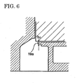
- Japanese Laid-Open Patent Publication (Kokai) No. H7-208362 proposes a screw compressor in which a radial discharge port 19a is formed by thin casting, and a thin portion can be removed for operation at a low pressure ratio and at a high rotation speed as shown in FIG. 6 .
- the size of the discharge port 19a can be easily optimized, the same cast casing can allegedly provide a high efficiency under a wide range of operation conditions.
- the present invention provides a screw compressor including a pair of male and female screw rotors that meshes with each other, and a casing that stores the pair of screw rotors, where the casing is divided into a discharge opening neighborhood portion including at least a discharge opening and an other portion other than the discharge opening neighborhood portion, and is configured so that the discharge opening neighborhood portion is removable from the other portion.
- the screw compressor configured as described above, during an operation in a medium or long period, even if operation conditions such as a suction pressure and a discharge pressure change, the discharge opening neighborhood portion can be replaced according to the operation conditions, and therefore, it is thus possible to minimize the power, and to attain energy saving. Moreover, since it is not necessary to produce an entire casing as in the conventional case, it is thus possible to reduce the time required for production, and simultaneously to reduce the cost.
- the casing may be divided, by dividing surfaces orthogonal to rotor shafts of the pair of screw rotors, into three portions including a rotor casing around the pair of screw rotors, a discharge casing on a side of the discharge opening, and a suction casing on a side of a suction opening, and the discharge opening neighborhood portion may be formed by dividing the rotor casing, and may be configured so as to be removable from the dividing surface on the side of the discharge opening of the divided rotor casing.
- the casing may be divided, by dividing surfaces orthogonal to rotor shafts of the pair of screw rotors, into three portions including a rotor casing around the pair of screw rotors, a discharge casing on a side of the discharge opening, and a suction casing on a side of a suction opening
- the discharge opening neighborhood portion may be formed by dividing the rotor casing, a length, in a direction of the rotor shafts, of the discharge opening neighborhood portion may be approximately the same as a length, in the direction of the rotor shafts, of the divided rotor casing, and the discharge opening neighborhood portion may be configured so as to be removable from either one of the dividing surfaces on the side of the discharge opening and on the side of the suction opening of the divided rotor casing.
- This configuration can eliminate the necessity for changing the length of the discharge opening neighborhood portion and a fitting length of the divided rotor casing according to a compression ratio and specifications, machining applied to a fitting portion of the rotor casing can thus be unified, and the time required for the production can be reduced.
- the casing may be divided, by a dividing surface orthogonal to rotor shafts of the pair of screw rotors, into two portions including a suction casing on a side of a suction opening, and a discharge/rotor casing on a side of the discharge opening, and around the pair of screw rotors, and the discharge opening neighborhood portion may be formed by dividing the discharge/rotor casing, a length, in a direction of the rotor shafts, of the discharge opening neighborhood portion may be approximately the same as a length of the rotor shafts, and the discharge opening neighborhood portion may be configured so as to be removable from the dividing surface on the side of the suction opening of the divided discharge/rotor casing.
- This configuration reduces the number of components, as well as eliminates the necessity for changing the length of the discharge opening neighborhood portion and the fitting length of the divided rotor casing according to a compression ratio and specifications. Therefore, the machining applied to a fitting portion of the rotor casing can thus be unified, and the time required for the production can be reduced.
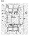
- FIG. 1 shows a casing configuration of the screw compressor according to the first embodiment of the present invention, and is a horizontal cross sectional view without screw rotors, viewed along arrows C-C in FIG. 2.
- FIG. 2 is a side cross sectional view, viewed along arrows A-A in FIG. 1 .
- FIG. 3 is an enlarged cross sectional view, viewed along arrows B-B in FIG. 1 .
- a pair of male and female screw rotors 7a and 7b meshes with each other, and are rotatably stored in a rotor chamber 8 formed inside a rotor casing 2 as shown in FIG. 2 . Then, only one of the pair of male and female screw rotors 7a and 7b, namely the male rotor 7a is connected to a driving shaft of a driving motor, which is not shown.
- the female rotor 7b is driven by the male rotor 7a, and a compression space is formed in a gap between these male rotor 7a and the female rotor 7b, the screw rotors 7a and 7b are rotated by the driving motor in a rotation direction indicated by arrows R in FIG. 2 , thereby sucking a gas supplied from a suction flow passage which is not shown, from a suction opening 3a of the screw rotors 7a and 7b of the compressor, compressing the gas, and discharging the compressed gas as a high pressure fluid from a discharge opening 6a of the screw rotors 7a and 7b to a discharge flow passage which is not shown.
- the casing 1 of the screw compressor is divided into three portions including the rotor casing 2, a suction casing 3 on the suction opening 3a side, and a discharge casing 4 on the discharge opening 6a side.
- a dividing surface 9a on the suction opening 3a side which divides the suction casing 3 and the rotor casing 2 from each other is formed so as to include a surface opposed to a rotor right end surface in a rotor chamber 8 (surface forming the suction opening 3a leading into the rotor chamber 8) in FIG.
- a dividing surface 9b on the discharge opening 6a side which divides the discharge casing 4 and the rotor casing 2 from each other is formed so as to include a surface opposed to a rotor left end surface in the rotor chamber 8 (surface forming the discharge opening 6a leading out from the rotor chamber 8) in FIG. 1 .
- a discharge opening neighborhood portion 6 including at least the discharge opening 6a is formed by dividing a part of the rotor casing 2, and is configured so as to be removable from the dividing surface 9b on the discharge opening 6a side of the remaining divided rotor casing 2a. Then, an other portion is constituted by the suction casing 3, the discharge casing 4, and the remaining dividing rotor casing 2a. In order to fix the discharge opening neighborhood portion 6 to the other portion, there may apply such a configuration that the respective portions have flange portions which are not shown, and these flange portions are screwed to each other, for example.
- the size of the discharge opening neighborhood portion 6 may have a length L, a width W, and a height H, which are respectively the maximum depth or more, the maximum width ore more, and the maximum height or more for possibly forming the discharge opening 6a. Moreover, it is not necessary to cut out the discharge opening neighborhood portion 6 from a part of the integrally-formed rotor casing 2 for forming it, and it is possible to form the discharge opening neighborhood portion 6 and the remaining divided rotor casing 2a separately from each other in advance. When the discharge opening neighborhood portion 6 and the remaining rotor casing 2a are formed separately from each other, it is preferable to use the same material for forming both of them in consideration of a uniform thermal expansion coefficient.
- the discharge opening neighborhood portion 6 can be replaced according to the operation conditions during an operation for a medium or long period, it is possible to minimize the power and to attain energy saving.
- it is not necessary to produce an entire casing as in the conventional case it is thus possible to reduce the time required for production, and simultaneously to reduce the cost.
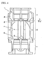
- FIG. 4 shows a casing configuration of the screw compressor according to the second embodiment of the present invention, and is a horizontal cross sectional view without screw rotors, viewed along arrows similarly to FIG. 1 .
- the second embodiment of the present invention is different from the first embodiment in a configuration of the discharge opening neighborhood portion, and the other configuration is exactly the same as that of the first embodiment, and a description will only be given to the configuration of the discharge opening neighborhood portion.
- the discharge opening neighborhood portion 6 is formed in the rotor shaft direction from the dividing surface 9b of the rotor casing 2, as the portion having the predetermined length L shorter than the length of the divided rotor casing 2a.
- the discharge opening neighborhood portion 6 is formed as a fitting portion which has the length L in the rotor shaft direction, and passes through the rotor casing 2 from the dividing surface 9b to the dividing surface 9a. Then, the discharge opening neighborhood portion 6 is configured so as to be removable either from the dividing surface 9a on the suction opening 3a side and the dividing surface 9b on the discharge opening 6a side of the divided rotor casing 2.
- the screw compressor according to the second embodiment of the present invention is formed as described above, it is not necessary to change the length L of the discharge opening neighborhood portion 6 according to the compression ratio or specifications, and the machining of the discharge opening neighborhood portion 6 in the rotor casing 2 can be unified, resulting in a reduction in period required for the production. Moreover, since the discharge opening neighborhood portion 6 is removable either from the suction opening 3a side and the discharge opening 6a side of the rotor casing 2, it is possible to properly select a method or the direction for the removal according to devices around the casing 1 and a configuration of piping or the like.
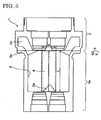
- FIG. 5 shows a casing configuration of the screw compressor according to the third embodiment of the present invention, and is a horizontal cross sectional view without screw rotors, viewed along arrows similar to FIG. 1 .
- the third embodiment of the present invention is different from the first embodiment in a division configuration of the casing, and a configuration of the discharge opening neighborhood portion, and the other configuration is exactly the same as that of the first embodiment, and therefore, a description will only be given to the division configuration of the casing, and the configuration of the discharge opening neighborhood portion.
- the casing 1 is divided, by the dividing surfaces 9a and 9b which are orthogonal to the rotor shafts, into three portions including the suction casing 3 on the suction opening 3a side, the rotor casing 2, and the discharge casing 4 on the discharge opening 6a side, and the discharge opening neighborhood portion 6 is configured in the rotor shaft direction from the dividing surface 9b of the rotor casing 2, as the portion having the predetermined length L shorter than the length of the divided rotor casing 2a.
- the casing 1 is divided by the dividing surface 9a orthogonal to the rotor shafts into two portions including the suction casing 3 on the suction opening 3a side and a discharge/rotor casing 5 on the discharge opening 6a side and around the screw rotors, while the discharge opening neighborhood portion 6 is formed by dividing the discharge/rotor casing 5, and the discharge opening neighborhood portion 6 is configured to have the length L in the rotor shaft direction as long as the rotor length. Then, the discharge opening neighborhood portion 6 is configured so as to be removable from the dividing surface 9a on the suction opening 3a side of a divided discharge/rotor casing 5a.
- the screw compressor according to the third embodiment of the present invention is configured as described above, the number of components is reduced compared with that of the second embodiment, and it is not necessary to change the length L of the discharge opening neighborhood portion 6 and a fitting length of the divided discharge/rotor casing 5a according to the compression ratio or specifications. Therefore, the machining of the discharge opening neighborhood portion 6 and the fitting portion of the divided discharge/rotor casing 5a can be unified, resulting in a reduction in period required for the production.
- the casing storing the screw rotors is divided into the discharge opening neighborhood portion including at least the discharge opening, and the other portion other than the discharge opening neighborhood portion.
- the discharge opening neighborhood portion is configured so as to be removable from the other portion. Therefore, even if operation conditions such as the suction pressure or the discharge pressure are changed during an operation in a medium and long period, it is possible to replace the discharge opening neighborhood portion according to the operation conditions, and thus it is possible to minimize the power and to attain the energy saving.
- it is not necessary to produce an entire casing as in the conventional case it is thus possible to reduce the time required for production, and simultaneously the cost.
- a screw compressor includes a pair of male and female screw rotors which meshes with each other, where a casing storing the pair of screw rotors is divided into a discharge opening neighborhood portion including at least a discharge opening and an other portion other than the discharge opening neighborhood portion, the discharge opening neighborhood portion is configured so as to be removable from the other portion, further, the casing is divided, by two dividing surfaces orthogonal to rotor shafts, into three portions including a rotor casing around the pair of screw rotors, a discharge casing on a side of the discharge opening, and a suction casing on a side of a suction opening, and the discharge opening neighborhood portion is formed by dividing the rotor casing, and is configured so as to be removable from the dividing surface on the side of the discharge opening of a divided rotor casing.
Landscapes
- Engineering & Computer Science (AREA)
- Mechanical Engineering (AREA)
- General Engineering & Computer Science (AREA)
- Applications Or Details Of Rotary Compressors (AREA)
Abstract
Description
- The present invention relates to a screw compressor which includes a pair of male and female screw rotors meshing with each other, and permits easy change of a size of a discharge opening even when operation conditions such as a compression ratio change.
- A performance of a screw compressor largely depends on a form (area and shape) of a discharge opening structured by an axial port (a discharge opening in the axial direction) and a radial port (a discharge opening in the radial direction). However, the size of the discharge opening of the screw compressor is usually fixed according to the operation conditions. In other words, this size of the discharge opening is determined by a design capacity ratio Vi defined by the following equation (1).
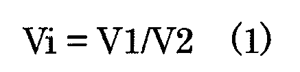
where: - V1: maximum suction capacity of rotor grooves, and
- V2: final discharge capacity of rotor grooves.
- A relationship between this design capacity ratio Vi and a design pressure ratio rri determined by operation conditions is represented by the following equation (2):

where: - P1: suction pressure,
- P2: final pressure in rotor grooves, and
- n: adiabatic exponent.
- Thus, if the optimal size of the discharge opening is determined for a discharge pressure Pd such that a relationship: Pd = P2 holds, it is possible to attain maximum efficiency. Though it is desirable to determine the form of the discharge opening according to the operation conditions of the screw compressor as described above, a reduction in number of man-hours required for producing the casing has conventionally been regarded as important, and the size of the discharge opening is not changed even if the operation conditions change in some degree.
- However, as a need for enhancement in performance and efficiency of screw compressors has recently been increasing, simply supplying screw compressors including a fixed discharge opening cannot meet this need, therefore, a screw compressor permitting easy change of the form of a discharge opening according to operation conditions while the number of man-hours required for producing is reduced has been sought for.
- For an application of a compressor used for drawing gas from an oilfield, for example, as a result of the drawing of the reserved gas for a medium or long period, the quantity of the reserved gas decreases, and the gas pressure to be drawn therefore decreases, resulting in a large displacement in the operation conditions from initial design conditions. Since an optimal form of the discharge opening cannot be secured due to the displacements from the initial design conditions to the operation conditions, a loss in power is thus generated, and a problem of a deteriorated efficiency can occur. Moreover, a deficiency in power of a driving source may require a reproduction of an entire compressor unit. In order to cope with the problem as described above, a need is increasing for a compressor which permits easy change of the form of a discharge opening.
- Under this technical background, as a conventional example, Japanese Laid-Open Patent Publication (Kokai) No.
H7-208362 radial discharge port 19a is formed by thin casting, and a thin portion can be removed for operation at a low pressure ratio and at a high rotation speed as shown inFIG. 6 . As a result, since the size of thedischarge port 19a can be easily optimized, the same cast casing can allegedly provide a high efficiency under a wide range of operation conditions. - However, for the discharge port of the screw compressor according to the conventional example, though the number of man-hours required for production is reduced compared with that required for technologies before this conventional example, a manufacturing process for removing a thin portion (thickness: h2) of the discharge port formed by casting according to the operation conditions still needs a large load in terms of machining/production, this conventional example cannot sufficiently meet the need for a compressor permitting easy change of the size of the discharge port according to the operation conditions, while reducing the number of man-hours required for the production.
- It is an object of the present invention to provide a screw compressor permitting easy change of the size of a discharge opening even if operation conditions change while the number of man-hours required for production thereof is reduced.
- In order to attain the above-described object, the present invention provides a screw compressor including a pair of male and female screw rotors that meshes with each other, and a casing that stores the pair of screw rotors, where the casing is divided into a discharge opening neighborhood portion including at least a discharge opening and an other portion other than the discharge opening neighborhood portion, and is configured so that the discharge opening neighborhood portion is removable from the other portion.
- According to the screw compressor configured as described above, during an operation in a medium or long period, even if operation conditions such as a suction pressure and a discharge pressure change, the discharge opening neighborhood portion can be replaced according to the operation conditions, and therefore, it is thus possible to minimize the power, and to attain energy saving. Moreover, since it is not necessary to produce an entire casing as in the conventional case, it is thus possible to reduce the time required for production, and simultaneously to reduce the cost.
- In the above-described screw compressor according to the present invention, the casing may be divided, by dividing surfaces orthogonal to rotor shafts of the pair of screw rotors, into three portions including a rotor casing around the pair of screw rotors, a discharge casing on a side of the discharge opening, and a suction casing on a side of a suction opening, and the discharge opening neighborhood portion may be formed by dividing the rotor casing, and may be configured so as to be removable from the dividing surface on the side of the discharge opening of the divided rotor casing.
- Moreover, in the above-described screw compressor according to the present invention, the casing may be divided, by dividing surfaces orthogonal to rotor shafts of the pair of screw rotors, into three portions including a rotor casing around the pair of screw rotors, a discharge casing on a side of the discharge opening, and a suction casing on a side of a suction opening, and the discharge opening neighborhood portion may be formed by dividing the rotor casing, a length, in a direction of the rotor shafts, of the discharge opening neighborhood portion may be approximately the same as a length, in the direction of the rotor shafts, of the divided rotor casing, and the discharge opening neighborhood portion may be configured so as to be removable from either one of the dividing surfaces on the side of the discharge opening and on the side of the suction opening of the divided rotor casing. This configuration can eliminate the necessity for changing the length of the discharge opening neighborhood portion and a fitting length of the divided rotor casing according to a compression ratio and specifications, machining applied to a fitting portion of the rotor casing can thus be unified, and the time required for the production can be reduced.
- Moreover, in the above-described screw compressor according to the present invention, the casing may be divided, by a dividing surface orthogonal to rotor shafts of the pair of screw rotors, into two portions including a suction casing on a side of a suction opening, and a discharge/rotor casing on a side of the discharge opening, and around the pair of screw rotors, and the discharge opening neighborhood portion may be formed by dividing the discharge/rotor casing, a length, in a direction of the rotor shafts, of the discharge opening neighborhood portion may be approximately the same as a length of the rotor shafts, and the discharge opening neighborhood portion may be configured so as to be removable from the dividing surface on the side of the suction opening of the divided discharge/rotor casing. This configuration reduces the number of components, as well as eliminates the necessity for changing the length of the discharge opening neighborhood portion and the fitting length of the divided rotor casing according to a compression ratio and specifications. Therefore, the machining applied to a fitting portion of the rotor casing can thus be unified, and the time required for the production can be reduced.
-
-
FIG. 1 shows a casing configuration of a screw compressor according to a first embodiment of the present invention, and is a horizontal cross sectional view without screw rotors, viewed along arrows C-C inFIG. 2 ; -
FIG. 2 is a side cross sectional view, viewed along arrows A-A inFIG. 1 ; -
FIG. 3 is an enlarged cross sectional view, viewed along arrows B-B inFIG. 1 ; -
FIG. 4 shows a casing configuration of the screw compressor according to a second embodiment of the present invention, and is a horizontal cross sectional view without screw rotors, viewed along arrows similarly toFIG. 1 ; -
FIG. 5 shows a casing configuration of the screw compressor according to a third embodiment of the present invention, and is a horizontal cross sectional view without screw rotors, viewed along arrows similarly toFIG. 1 ; and -
FIG. 6 describes a discharge port of a screw compressor according to a conventional example. - First, a description will now be given to a screw compressor according to a first embodiment of the present invention with reference to
FIGS. 1 to 3 .FIG. 1 shows a casing configuration of the screw compressor according to the first embodiment of the present invention, and is a horizontal cross sectional view without screw rotors, viewed along arrows C-C inFIG. 2. FIG. 2 is a side cross sectional view, viewed along arrows A-A inFIG. 1 .FIG. 3 is an enlarged cross sectional view, viewed along arrows B-B inFIG. 1 . - With respect to the screw compressor according to the first embodiment of the present invention, a pair of male and
female screw rotors rotor chamber 8 formed inside a rotor casing 2 as shown inFIG. 2 . Then, only one of the pair of male andfemale screw rotors male rotor 7a is connected to a driving shaft of a driving motor, which is not shown. - The
female rotor 7b is driven by themale rotor 7a, and a compression space is formed in a gap between thesemale rotor 7a and thefemale rotor 7b, thescrew rotors FIG. 2 , thereby sucking a gas supplied from a suction flow passage which is not shown, from asuction opening 3a of thescrew rotors screw rotors - In the screw compressor according to the first embodiment of the present invention, the casing 1 of the screw compressor is divided into three portions including the rotor casing 2, a suction casing 3 on the suction opening 3a side, and a discharge casing 4 on the discharge opening 6a side. A dividing
surface 9a on thesuction opening 3a side which divides the suction casing 3 and the rotor casing 2 from each other is formed so as to include a surface opposed to a rotor right end surface in a rotor chamber 8 (surface forming thesuction opening 3a leading into the rotor chamber 8) inFIG. 1 , and a dividingsurface 9b on the discharge opening 6a side which divides the discharge casing 4 and the rotor casing 2 from each other is formed so as to include a surface opposed to a rotor left end surface in the rotor chamber 8 (surface forming thedischarge opening 6a leading out from the rotor chamber 8) inFIG. 1 . - Further, a discharge
opening neighborhood portion 6 including at least thedischarge opening 6a is formed by dividing a part of the rotor casing 2, and is configured so as to be removable from the dividingsurface 9b on thedischarge opening 6a side of the remaining dividedrotor casing 2a. Then, an other portion is constituted by the suction casing 3, the discharge casing 4, and the remaining dividingrotor casing 2a. In order to fix the discharge openingneighborhood portion 6 to the other portion, there may apply such a configuration that the respective portions have flange portions which are not shown, and these flange portions are screwed to each other, for example. - The size of the discharge opening
neighborhood portion 6 may have a length L, a width W, and a height H, which are respectively the maximum depth or more, the maximum width ore more, and the maximum height or more for possibly forming thedischarge opening 6a. Moreover, it is not necessary to cut out the discharge openingneighborhood portion 6 from a part of the integrally-formed rotor casing 2 for forming it, and it is possible to form the dischargeopening neighborhood portion 6 and the remaining dividedrotor casing 2a separately from each other in advance. When the discharge openingneighborhood portion 6 and theremaining rotor casing 2a are formed separately from each other, it is preferable to use the same material for forming both of them in consideration of a uniform thermal expansion coefficient. - With this configuration, the discharge opening
neighborhood portion 6 having the discharge opening 6a optimized (optimized in terms of the size of an opening area of the discharge opening 6a, for example) according to changes in operation conditions such as the suction pressure and the discharge pressure, is produced, and is configured so as to be removable from therotor casing 2a of the other portion. As a result, since the discharge openingneighborhood portion 6 can be replaced according to the operation conditions during an operation for a medium or long period, it is possible to minimize the power and to attain energy saving. Moreover, since it is not necessary to produce an entire casing as in the conventional case, it is thus possible to reduce the time required for production, and simultaneously to reduce the cost. - A description will now be given to the screw compressor according to a second embodiment of the present invention with reference to
FIG. 4. FIG. 4 shows a casing configuration of the screw compressor according to the second embodiment of the present invention, and is a horizontal cross sectional view without screw rotors, viewed along arrows similarly toFIG. 1 . The second embodiment of the present invention is different from the first embodiment in a configuration of the discharge opening neighborhood portion, and the other configuration is exactly the same as that of the first embodiment, and a description will only be given to the configuration of the discharge opening neighborhood portion. - In other words, the discharge
opening neighborhood portion 6 according to the first embodiment is formed in the rotor shaft direction from the dividingsurface 9b of the rotor casing 2, as the portion having the predetermined length L shorter than the length of the dividedrotor casing 2a. - On the other hand, according to the second embodiment of the present invention, the discharge
opening neighborhood portion 6 is formed as a fitting portion which has the length L in the rotor shaft direction, and passes through the rotor casing 2 from the dividingsurface 9b to the dividingsurface 9a. Then, the dischargeopening neighborhood portion 6 is configured so as to be removable either from the dividingsurface 9a on thesuction opening 3a side and the dividingsurface 9b on thedischarge opening 6a side of the divided rotor casing 2. - Since the screw compressor according to the second embodiment of the present invention is formed as described above, it is not necessary to change the length L of the discharge
opening neighborhood portion 6 according to the compression ratio or specifications, and the machining of the dischargeopening neighborhood portion 6 in the rotor casing 2 can be unified, resulting in a reduction in period required for the production. Moreover, since the dischargeopening neighborhood portion 6 is removable either from thesuction opening 3a side and thedischarge opening 6a side of the rotor casing 2, it is possible to properly select a method or the direction for the removal according to devices around the casing 1 and a configuration of piping or the like. - A description will now be given to the screw compressor according to a third embodiment of the present invention with reference to
FIG. 5. FIG. 5 shows a casing configuration of the screw compressor according to the third embodiment of the present invention, and is a horizontal cross sectional view without screw rotors, viewed along arrows similar toFIG. 1 . The third embodiment of the present invention is different from the first embodiment in a division configuration of the casing, and a configuration of the discharge opening neighborhood portion, and the other configuration is exactly the same as that of the first embodiment, and therefore, a description will only be given to the division configuration of the casing, and the configuration of the discharge opening neighborhood portion. - In other words, according to the first embodiment of the present invention, the casing 1 is divided, by the dividing surfaces 9a and 9b which are orthogonal to the rotor shafts, into three portions including the suction casing 3 on the
suction opening 3a side, the rotor casing 2, and the discharge casing 4 on thedischarge opening 6a side, and the dischargeopening neighborhood portion 6 is configured in the rotor shaft direction from the dividingsurface 9b of the rotor casing 2, as the portion having the predetermined length L shorter than the length of the dividedrotor casing 2a. - On the other hand, according to the third embodiment of the present invention, the casing 1 is divided by the dividing
surface 9a orthogonal to the rotor shafts into two portions including the suction casing 3 on thesuction opening 3a side and a discharge/rotor casing 5 on thedischarge opening 6a side and around the screw rotors, while the dischargeopening neighborhood portion 6 is formed by dividing the discharge/rotor casing 5, and the dischargeopening neighborhood portion 6 is configured to have the length L in the rotor shaft direction as long as the rotor length. Then, the dischargeopening neighborhood portion 6 is configured so as to be removable from the dividingsurface 9a on thesuction opening 3a side of a divided discharge/rotor casing 5a. - Since the screw compressor according to the third embodiment of the present invention is configured as described above, the number of components is reduced compared with that of the second embodiment, and it is not necessary to change the length L of the discharge
opening neighborhood portion 6 and a fitting length of the divided discharge/rotor casing 5a according to the compression ratio or specifications. Therefore, the machining of the dischargeopening neighborhood portion 6 and the fitting portion of the divided discharge/rotor casing 5a can be unified, resulting in a reduction in period required for the production. - It should be noted that especially many conventional oilless screw compressor originally have a casing divided into two potions including a suction casing and a discharge/rotor casing as described above. Thus, it is possible, by machining the casing of the conventional oilless screw compressor, to convert it into the casing 1 (the suction casing 3 and the discharge/rotor casing 5) of the screw compressor according to the third embodiment of the present invention.
- As described above, in the screw compressors according to the present invention, the casing storing the screw rotors is divided into the discharge opening neighborhood portion including at least the discharge opening, and the other portion other than the discharge opening neighborhood portion. And the discharge opening neighborhood portion is configured so as to be removable from the other portion. Therefore, even if operation conditions such as the suction pressure or the discharge pressure are changed during an operation in a medium and long period, it is possible to replace the discharge opening neighborhood portion according to the operation conditions, and thus it is possible to minimize the power and to attain the energy saving. Moreover, since it is not necessary to produce an entire casing as in the conventional case, it is thus possible to reduce the time required for production, and simultaneously the cost.
- A screw compressor includes a pair of male and female screw rotors which meshes with each other, where a casing storing the pair of screw rotors is divided into a discharge opening neighborhood portion including at least a discharge opening and an other portion other than the discharge opening neighborhood portion, the discharge opening neighborhood portion is configured so as to be removable from the other portion, further, the casing is divided, by two dividing surfaces orthogonal to rotor shafts, into three portions including a rotor casing around the pair of screw rotors, a discharge casing on a side of the discharge opening, and a suction casing on a side of a suction opening, and the discharge opening neighborhood portion is formed by dividing the rotor casing, and is configured so as to be removable from the dividing surface on the side of the discharge opening of a divided rotor casing. According to this configuration, the number of man-hours required for production thereof is reduced, and if operation conditions change, the size of a discharge opening can be easily changed.
Claims (4)
- A screw compressor comprising:a pair of male and female screw rotors that meshes with each other anda casing that stores said pair of screw rotors,wherein said casing is divided into a discharge opening neighborhood portion comprising at least a discharge opening, and an other portion other than said discharge opening neighborhood portion, and is configured so that said discharge opening neighborhood portion is removable from said other portion.
- The screw compressor according to claim 1, wherein:said casing is divided, by dividing surfaces orthogonal to rotor shafts of said pair of screw rotors, into three portions including a rotor casing around said pair of screw rotors, a discharge casing on a side of said discharge opening, and a suction casing on a side of a suction opening, andsaid discharge opening neighborhood portion is formed by dividing said rotor casing, and is configured so as to be removable from said dividing surface on the side of said discharge opening of said divided rotor casing.
- The screw compressor according to claim 1, wherein:said casing is divided, by dividing surfaces orthogonal to rotor shafts of said pair of screw rotors, into three portions including a rotor casing around said pair of screw rotors, a discharge casing on a side of said discharge opening, and a suction casing on a side of a suction opening,said discharge opening neighborhood portion is formed by dividing said rotor casing,a length, in a direction of said rotor shafts, of said discharge opening neighborhood portion is approximately the same as a length, in the direction of said rotor shafts, of said divided rotor casing, andsaid discharge opening neighborhood portion is configured so as to be removable from either one of said dividing surfaces on the side of said discharge opening and on the side of said suction opening of said divided rotor casing.
- The screw compressor according to claim 1, wherein:said casing is divided, by a dividing surface orthogonal to rotor shafts of said pair of screw rotors, into two portions including a suction casing on a side of a suction opening, and a discharge/rotor casing on a side of said discharge opening and around said pair of screw rotors,said discharge opening neighborhood portion is formed by dividing said discharge/rotor casing,a length, in a direction of said rotor shafts, of said discharge opening neighborhood portion is approximately the same as a length of said rotors, andsaid discharge opening neighborhood portion is configured so as to be removable from said dividing surface on the side of said suction opening of said divided discharge/rotor casing.
Applications Claiming Priority (1)
| Application Number | Priority Date | Filing Date | Title |
|---|---|---|---|
| JP2008180499A JP5180709B2 (en) | 2008-07-10 | 2008-07-10 | Screw compressor |
Publications (3)
| Publication Number | Publication Date |
|---|---|
| EP2143951A2 true EP2143951A2 (en) | 2010-01-13 |
| EP2143951A3 EP2143951A3 (en) | 2014-06-25 |
| EP2143951B1 EP2143951B1 (en) | 2018-02-28 |
Family
ID=40875090
Family Applications (1)
| Application Number | Title | Priority Date | Filing Date |
|---|---|---|---|
| EP09160619.4A Not-in-force EP2143951B1 (en) | 2008-07-10 | 2009-05-19 | Screw compressor |
Country Status (3)
| Country | Link |
|---|---|
| US (1) | US8147231B2 (en) |
| EP (1) | EP2143951B1 (en) |
| JP (1) | JP5180709B2 (en) |
Cited By (1)
| Publication number | Priority date | Publication date | Assignee | Title |
|---|---|---|---|---|
| EP3431764A1 (en) * | 2017-07-19 | 2019-01-23 | Marschall, Rouven | Sinusoidal pump |
Families Citing this family (5)
| Publication number | Priority date | Publication date | Assignee | Title |
|---|---|---|---|---|
| US8206360B2 (en) | 2005-02-01 | 2012-06-26 | Intelliject, Inc. | Devices, systems and methods for medicament delivery |
| WO2011092937A1 (en) | 2010-01-29 | 2011-08-04 | オリンパスメディカルシステムズ株式会社 | Inserting apparatus and endoscope |
| JP2012172627A (en) * | 2011-02-23 | 2012-09-10 | Kobe Steel Ltd | Screw compressor |
| CN102817844B (en) * | 2012-09-14 | 2015-09-09 | 上海齐耀螺杆机械有限公司 | A kind of helical-lobe compressor |
| CN105402132B (en) * | 2015-12-28 | 2024-07-09 | 珠海凌达压缩机有限公司 | Cylinder assembly and compressor comprising same |
Citations (1)
| Publication number | Priority date | Publication date | Assignee | Title |
|---|---|---|---|---|
| JPH07208362A (en) | 1994-01-13 | 1995-08-08 | Hitachi Ltd | Discharge port of screw compressor |
Family Cites Families (13)
| Publication number | Priority date | Publication date | Assignee | Title |
|---|---|---|---|---|
| BE488315A (en) * | ||||
| JPS576789Y2 (en) * | 1975-02-26 | 1982-02-08 | ||
| JP2650897B2 (en) * | 1986-10-27 | 1997-09-10 | 株式会社日立製作所 | Screw vacuum pump for semiconductor manufacturing equipment |
| SE462232B (en) * | 1988-11-16 | 1990-05-21 | Svenska Rotor Maskiner Ab | SCREW COMPRESSOR WITH OIL DRAINAGE |
| JPH0315689A (en) * | 1989-06-12 | 1991-01-24 | Kobe Steel Ltd | Screw compressor |
| JP2704039B2 (en) * | 1990-11-08 | 1998-01-26 | 株式会社神戸製鋼所 | Screw compressor |
| JPH04203385A (en) * | 1990-11-30 | 1992-07-23 | Hitachi Ltd | Screw vacuum pump |
| JP2000337283A (en) * | 1999-05-28 | 2000-12-05 | Tochigi Fuji Ind Co Ltd | Screw compressor |
| JP4686936B2 (en) * | 2000-10-30 | 2011-05-25 | 株式会社デンソー | Screw compressor |
| US6672856B1 (en) * | 2002-06-28 | 2004-01-06 | Carrier Corporation | Diffuser guide vanes for high-speed screw compressor |
| US6786710B2 (en) * | 2002-08-27 | 2004-09-07 | Carrier Corporation | Discharge porting for screw compressor with tangential flow guide cusp |
| ITBO20030781A1 (en) * | 2003-12-23 | 2005-06-24 | Hoerbiger Italiana S P A | SUCTION VALVE ASSEMBLY FOR SCREW COMPRESSOR UNITS |
| JP5011297B2 (en) * | 2005-08-25 | 2012-08-29 | アテリエ ビスク ソシエテ アノニム | Pump casing |
-
2008
- 2008-07-10 JP JP2008180499A patent/JP5180709B2/en not_active Expired - Fee Related
-
2009
- 2009-05-12 US US12/464,502 patent/US8147231B2/en active Active
- 2009-05-19 EP EP09160619.4A patent/EP2143951B1/en not_active Not-in-force
Patent Citations (1)
| Publication number | Priority date | Publication date | Assignee | Title |
|---|---|---|---|---|
| JPH07208362A (en) | 1994-01-13 | 1995-08-08 | Hitachi Ltd | Discharge port of screw compressor |
Cited By (1)
| Publication number | Priority date | Publication date | Assignee | Title |
|---|---|---|---|---|
| EP3431764A1 (en) * | 2017-07-19 | 2019-01-23 | Marschall, Rouven | Sinusoidal pump |
Also Published As
| Publication number | Publication date |
|---|---|
| US20100008811A1 (en) | 2010-01-14 |
| EP2143951A3 (en) | 2014-06-25 |
| EP2143951B1 (en) | 2018-02-28 |
| US8147231B2 (en) | 2012-04-03 |
| JP5180709B2 (en) | 2013-04-10 |
| JP2010019170A (en) | 2010-01-28 |
Similar Documents
| Publication | Publication Date | Title |
|---|---|---|
| EP2143951B1 (en) | Screw compressor | |
| EP2703648B1 (en) | Scroll compressor | |
| US11415134B2 (en) | Screw rotor, fluid machine main body, and fluid machine | |
| JP2009074554A (en) | Multi-stage spiral screw rotor | |
| JP5461313B2 (en) | Scroll compressor and discharge port machining method thereof | |
| KR20190043139A (en) | Dry compressed vacuum pump | |
| EP2264319B1 (en) | Oil free screw compressor | |
| JP6983872B2 (en) | Vacuum pump screw rotor | |
| CN109642573B (en) | Screw vacuum pump | |
| US11225965B2 (en) | Screw rotor and fluid machine body | |
| EP2169229A1 (en) | Single screw compressor | |
| JP4403739B2 (en) | Screw compressor | |
| JP2012137000A (en) | Scroll compressor | |
| JP2000110760A (en) | Oil-cooled screw compressor | |
| CN111448392B (en) | compressor | |
| US11536270B2 (en) | Screw rotor and screw-type fluid machine main body | |
| JP4350603B2 (en) | Gas compressor | |
| JP2009002326A (en) | Screw compressor | |
| JP3403452B2 (en) | Oilless screw compressor | |
| JP3073889U (en) | Compound twin screw rotor device | |
| JP2012172627A (en) | Screw compressor | |
| JP2006322414A (en) | Vane for rotary type compressor and method for manufacturing same | |
| JP2008248823A (en) | Scroll fluid machinery | |
| CN107542661A (en) | Single cylinder rotary compressor | |
| JP2000337281A (en) | Gas compressor |
Legal Events
| Date | Code | Title | Description |
|---|---|---|---|
| PUAI | Public reference made under article 153(3) epc to a published international application that has entered the european phase |
Free format text: ORIGINAL CODE: 0009012 |
|
| 17P | Request for examination filed |
Effective date: 20090519 |
|
| AK | Designated contracting states |
Kind code of ref document: A2 Designated state(s): AT BE BG CH CY CZ DE DK EE ES FI FR GB GR HR HU IE IS IT LI LT LU LV MC MK MT NL NO PL PT RO SE SI SK TR |
|
| PUAL | Search report despatched |
Free format text: ORIGINAL CODE: 0009013 |
|
| AK | Designated contracting states |
Kind code of ref document: A3 Designated state(s): AT BE BG CH CY CZ DE DK EE ES FI FR GB GR HR HU IE IS IT LI LT LU LV MC MK MT NL NO PL PT RO SE SI SK TR |
|
| RIC1 | Information provided on ipc code assigned before grant |
Ipc: F04C 18/08 20060101ALI20140522BHEP Ipc: F04C 18/16 20060101AFI20140522BHEP |
|
| RBV | Designated contracting states (corrected) |
Designated state(s): AT BE BG CH CY CZ DE DK EE ES FI FR GB GR HR HU IE IS IT LI LT LU LV MC MK MT NL NO PL PT RO SE SI SK TR |
|
| 17Q | First examination report despatched |
Effective date: 20160728 |
|
| GRAP | Despatch of communication of intention to grant a patent |
Free format text: ORIGINAL CODE: EPIDOSNIGR1 |
|
| INTG | Intention to grant announced |
Effective date: 20170921 |
|
| RIN1 | Information on inventor provided before grant (corrected) |
Inventor name: AMANO, YASUSHI Inventor name: KITANO, TOSHIKI |
|
| GRAS | Grant fee paid |
Free format text: ORIGINAL CODE: EPIDOSNIGR3 |
|
| GRAA | (expected) grant |
Free format text: ORIGINAL CODE: 0009210 |
|
| AK | Designated contracting states |
Kind code of ref document: B1 Designated state(s): AT BE BG CH CY CZ DE DK EE ES FI FR GB GR HR HU IE IS IT LI LT LU LV MC MK MT NL NO PL PT RO SE SI SK TR |
|
| REG | Reference to a national code |
Ref country code: GB Ref legal event code: FG4D Ref country code: CH Ref legal event code: EP |
|
| REG | Reference to a national code |
Ref country code: AT Ref legal event code: REF Ref document number: 974473 Country of ref document: AT Kind code of ref document: T Effective date: 20180315 |
|
| REG | Reference to a national code |
Ref country code: IE Ref legal event code: FG4D |
|
| REG | Reference to a national code |
Ref country code: DE Ref legal event code: R096 Ref document number: 602009050950 Country of ref document: DE |
|
| REG | Reference to a national code |
Ref country code: SE Ref legal event code: TRGR |
|
| REG | Reference to a national code |
Ref country code: NL Ref legal event code: MP Effective date: 20180228 |
|
| REG | Reference to a national code |
Ref country code: LT Ref legal event code: MG4D |
|
| REG | Reference to a national code |
Ref country code: AT Ref legal event code: MK05 Ref document number: 974473 Country of ref document: AT Kind code of ref document: T Effective date: 20180228 |
|
| PG25 | Lapsed in a contracting state [announced via postgrant information from national office to epo] |
Ref country code: LT Free format text: LAPSE BECAUSE OF FAILURE TO SUBMIT A TRANSLATION OF THE DESCRIPTION OR TO PAY THE FEE WITHIN THE PRESCRIBED TIME-LIMIT Effective date: 20180228 Ref country code: CY Free format text: LAPSE BECAUSE OF FAILURE TO SUBMIT A TRANSLATION OF THE DESCRIPTION OR TO PAY THE FEE WITHIN THE PRESCRIBED TIME-LIMIT Effective date: 20180228 Ref country code: FI Free format text: LAPSE BECAUSE OF FAILURE TO SUBMIT A TRANSLATION OF THE DESCRIPTION OR TO PAY THE FEE WITHIN THE PRESCRIBED TIME-LIMIT Effective date: 20180228 Ref country code: NO Free format text: LAPSE BECAUSE OF FAILURE TO SUBMIT A TRANSLATION OF THE DESCRIPTION OR TO PAY THE FEE WITHIN THE PRESCRIBED TIME-LIMIT Effective date: 20180528 Ref country code: ES Free format text: LAPSE BECAUSE OF FAILURE TO SUBMIT A TRANSLATION OF THE DESCRIPTION OR TO PAY THE FEE WITHIN THE PRESCRIBED TIME-LIMIT Effective date: 20180228 Ref country code: NL Free format text: LAPSE BECAUSE OF FAILURE TO SUBMIT A TRANSLATION OF THE DESCRIPTION OR TO PAY THE FEE WITHIN THE PRESCRIBED TIME-LIMIT Effective date: 20180228 Ref country code: HR Free format text: LAPSE BECAUSE OF FAILURE TO SUBMIT A TRANSLATION OF THE DESCRIPTION OR TO PAY THE FEE WITHIN THE PRESCRIBED TIME-LIMIT Effective date: 20180228 |
|
| PG25 | Lapsed in a contracting state [announced via postgrant information from national office to epo] |
Ref country code: LV Free format text: LAPSE BECAUSE OF FAILURE TO SUBMIT A TRANSLATION OF THE DESCRIPTION OR TO PAY THE FEE WITHIN THE PRESCRIBED TIME-LIMIT Effective date: 20180228 Ref country code: BG Free format text: LAPSE BECAUSE OF FAILURE TO SUBMIT A TRANSLATION OF THE DESCRIPTION OR TO PAY THE FEE WITHIN THE PRESCRIBED TIME-LIMIT Effective date: 20180528 Ref country code: AT Free format text: LAPSE BECAUSE OF FAILURE TO SUBMIT A TRANSLATION OF THE DESCRIPTION OR TO PAY THE FEE WITHIN THE PRESCRIBED TIME-LIMIT Effective date: 20180228 Ref country code: GR Free format text: LAPSE BECAUSE OF FAILURE TO SUBMIT A TRANSLATION OF THE DESCRIPTION OR TO PAY THE FEE WITHIN THE PRESCRIBED TIME-LIMIT Effective date: 20180529 |
|
| PG25 | Lapsed in a contracting state [announced via postgrant information from national office to epo] |
Ref country code: PL Free format text: LAPSE BECAUSE OF FAILURE TO SUBMIT A TRANSLATION OF THE DESCRIPTION OR TO PAY THE FEE WITHIN THE PRESCRIBED TIME-LIMIT Effective date: 20180228 Ref country code: EE Free format text: LAPSE BECAUSE OF FAILURE TO SUBMIT A TRANSLATION OF THE DESCRIPTION OR TO PAY THE FEE WITHIN THE PRESCRIBED TIME-LIMIT Effective date: 20180228 Ref country code: RO Free format text: LAPSE BECAUSE OF FAILURE TO SUBMIT A TRANSLATION OF THE DESCRIPTION OR TO PAY THE FEE WITHIN THE PRESCRIBED TIME-LIMIT Effective date: 20180228 Ref country code: IT Free format text: LAPSE BECAUSE OF FAILURE TO SUBMIT A TRANSLATION OF THE DESCRIPTION OR TO PAY THE FEE WITHIN THE PRESCRIBED TIME-LIMIT Effective date: 20180228 |
|
| REG | Reference to a national code |
Ref country code: DE Ref legal event code: R097 Ref document number: 602009050950 Country of ref document: DE |
|
| PG25 | Lapsed in a contracting state [announced via postgrant information from national office to epo] |
Ref country code: SK Free format text: LAPSE BECAUSE OF FAILURE TO SUBMIT A TRANSLATION OF THE DESCRIPTION OR TO PAY THE FEE WITHIN THE PRESCRIBED TIME-LIMIT Effective date: 20180228 Ref country code: DK Free format text: LAPSE BECAUSE OF FAILURE TO SUBMIT A TRANSLATION OF THE DESCRIPTION OR TO PAY THE FEE WITHIN THE PRESCRIBED TIME-LIMIT Effective date: 20180228 Ref country code: CZ Free format text: LAPSE BECAUSE OF FAILURE TO SUBMIT A TRANSLATION OF THE DESCRIPTION OR TO PAY THE FEE WITHIN THE PRESCRIBED TIME-LIMIT Effective date: 20180228 |
|
| REG | Reference to a national code |
Ref country code: CH Ref legal event code: PL |
|
| PLBE | No opposition filed within time limit |
Free format text: ORIGINAL CODE: 0009261 |
|
| STAA | Information on the status of an ep patent application or granted ep patent |
Free format text: STATUS: NO OPPOSITION FILED WITHIN TIME LIMIT |
|
| REG | Reference to a national code |
Ref country code: BE Ref legal event code: MM Effective date: 20180531 |
|
| PG25 | Lapsed in a contracting state [announced via postgrant information from national office to epo] |
Ref country code: MC Free format text: LAPSE BECAUSE OF FAILURE TO SUBMIT A TRANSLATION OF THE DESCRIPTION OR TO PAY THE FEE WITHIN THE PRESCRIBED TIME-LIMIT Effective date: 20180228 |
|
| 26N | No opposition filed |
Effective date: 20181129 |
|
| REG | Reference to a national code |
Ref country code: IE Ref legal event code: MM4A |
|
| PG25 | Lapsed in a contracting state [announced via postgrant information from national office to epo] |
Ref country code: LI Free format text: LAPSE BECAUSE OF NON-PAYMENT OF DUE FEES Effective date: 20180531 Ref country code: SI Free format text: LAPSE BECAUSE OF FAILURE TO SUBMIT A TRANSLATION OF THE DESCRIPTION OR TO PAY THE FEE WITHIN THE PRESCRIBED TIME-LIMIT Effective date: 20180228 Ref country code: CH Free format text: LAPSE BECAUSE OF NON-PAYMENT OF DUE FEES Effective date: 20180531 |
|
| PG25 | Lapsed in a contracting state [announced via postgrant information from national office to epo] |
Ref country code: LU Free format text: LAPSE BECAUSE OF NON-PAYMENT OF DUE FEES Effective date: 20180519 |
|
| PG25 | Lapsed in a contracting state [announced via postgrant information from national office to epo] |
Ref country code: IE Free format text: LAPSE BECAUSE OF NON-PAYMENT OF DUE FEES Effective date: 20180519 Ref country code: FR Free format text: LAPSE BECAUSE OF NON-PAYMENT OF DUE FEES Effective date: 20180531 |
|
| PG25 | Lapsed in a contracting state [announced via postgrant information from national office to epo] |
Ref country code: BE Free format text: LAPSE BECAUSE OF NON-PAYMENT OF DUE FEES Effective date: 20180531 |
|
| PG25 | Lapsed in a contracting state [announced via postgrant information from national office to epo] |
Ref country code: MT Free format text: LAPSE BECAUSE OF NON-PAYMENT OF DUE FEES Effective date: 20180519 |
|
| PG25 | Lapsed in a contracting state [announced via postgrant information from national office to epo] |
Ref country code: TR Free format text: LAPSE BECAUSE OF FAILURE TO SUBMIT A TRANSLATION OF THE DESCRIPTION OR TO PAY THE FEE WITHIN THE PRESCRIBED TIME-LIMIT Effective date: 20180228 |
|
| PG25 | Lapsed in a contracting state [announced via postgrant information from national office to epo] |
Ref country code: HU Free format text: LAPSE BECAUSE OF FAILURE TO SUBMIT A TRANSLATION OF THE DESCRIPTION OR TO PAY THE FEE WITHIN THE PRESCRIBED TIME-LIMIT; INVALID AB INITIO Effective date: 20090519 Ref country code: PT Free format text: LAPSE BECAUSE OF FAILURE TO SUBMIT A TRANSLATION OF THE DESCRIPTION OR TO PAY THE FEE WITHIN THE PRESCRIBED TIME-LIMIT Effective date: 20180228 |
|
| PG25 | Lapsed in a contracting state [announced via postgrant information from national office to epo] |
Ref country code: MK Free format text: LAPSE BECAUSE OF NON-PAYMENT OF DUE FEES Effective date: 20180228 |
|
| PG25 | Lapsed in a contracting state [announced via postgrant information from national office to epo] |
Ref country code: IS Free format text: LAPSE BECAUSE OF FAILURE TO SUBMIT A TRANSLATION OF THE DESCRIPTION OR TO PAY THE FEE WITHIN THE PRESCRIBED TIME-LIMIT Effective date: 20180628 |
|
| PGFP | Annual fee paid to national office [announced via postgrant information from national office to epo] |
Ref country code: SE Payment date: 20230310 Year of fee payment: 15 Ref country code: GB Payment date: 20230330 Year of fee payment: 15 |
|
| P01 | Opt-out of the competence of the unified patent court (upc) registered |
Effective date: 20230523 |
|
| PGFP | Annual fee paid to national office [announced via postgrant information from national office to epo] |
Ref country code: DE Payment date: 20230321 Year of fee payment: 15 |
|
| REG | Reference to a national code |
Ref country code: DE Ref legal event code: R119 Ref document number: 602009050950 Country of ref document: DE |
|
| REG | Reference to a national code |
Ref country code: SE Ref legal event code: EUG |
|
| GBPC | Gb: european patent ceased through non-payment of renewal fee |
Effective date: 20240519 |
|
| PG25 | Lapsed in a contracting state [announced via postgrant information from national office to epo] |
Ref country code: DE Free format text: LAPSE BECAUSE OF NON-PAYMENT OF DUE FEES Effective date: 20241203 |
|
| PG25 | Lapsed in a contracting state [announced via postgrant information from national office to epo] |
Ref country code: GB Free format text: LAPSE BECAUSE OF NON-PAYMENT OF DUE FEES Effective date: 20240519 |
|
| PG25 | Lapsed in a contracting state [announced via postgrant information from national office to epo] |
Ref country code: SE Free format text: LAPSE BECAUSE OF NON-PAYMENT OF DUE FEES Effective date: 20240520 |